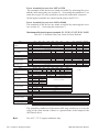
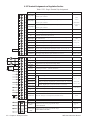
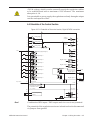
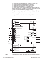
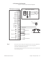
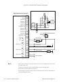
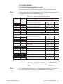
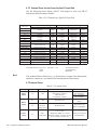
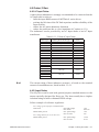
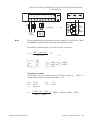
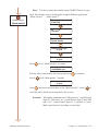
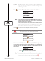
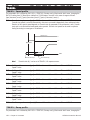
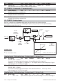
1
ARTDriveL
Lift Vector AC Drives
ARTDriveL
AVy...-...-AC
AVy...-...-AC4
AVy...-...-BR
AVy...-...-BR4
......
Instruction Manual
Thank you for choosing this Gefran-Siei product.
We will be glad to receive any possible information which could help us
improving this manual. The e-mail address is the following: [email protected].
Before using the product, read the safety instruction section carefully.
Keep the manual in a safe place and available to engineering and installation
personnel during the product functioning period.
Gefran spa has the right to modify products, data and dimensions without notice.
The data can only be used for the product description and they can not be
understood as legally stated properties.
All rights reserved
This manual is updated according to software version 3.6XX and RV33-4NV
regulation card.
The identification number of the software version can be read on the inverter
nameplate or on the label on the FLASH memories mounted on the regulation
card.
Table of Contents
Safety Symbol Legend - Precautions de securité ............................................................ 6
Chapter 0 - Safety Precautions ........................................................................................ 7
Chapter 1 - Functions and General Features ................................................................. 13
1.1 Drive ......................................................................................................................................... 13
1.2 Motors ..................................................................................................................................... 15
Chapter 2 - Inspection procedures, Components Identification and Standard
Specifications ............................................................................................... 17
2.1 Upon Delivery Inspection Procedures ...................................................................................... 17
2.1.1 General ...................................................................................................................................................
2.1.2 Inverter type designation .......................................................................................................................
2.1.3 Nameplate ..............................................................................................................................................
Figure 2.1.3.1: Identification nameplate ....................................................................................................
Figure 2.1.3.2: Firmware & Card revision level nameplate ........................................................................
Figure 2.1.3.3: Nameplates position ..........................................................................................................
17
17
18
18
18
18
2.2 Component Identification ......................................................................................................... 19
Figure 2.2.1: Basic Setup of Frequency Inverter ....................................................................................... 19
2.3 Standard Specifications ........................................................................................................... 20
2.3.1 Permissible Environmental Conditions ...................................................................................................
Disposal of the Device .....................................................................................................................................
2.3.2 AC Input/Output Connection ..................................................................................................................
2.3.3 AC Input .................................................................................................................................................
2.3.4 AC Output ...............................................................................................................................................
Figure 2.3.4.1: Rating of Drive in Function of Switching Frequency ..........................................................
Table 2.3.4.1: AC Input/Output Specifications ...........................................................................................
Table 2.3.4.2-A: Overload Capability (Sizes 1007 ... 4370) .......................................................................
Table 2.3.4.2-B: Overload Capability (Sizes 5450... 81600) ......................................................................
2.3.6 Accuracy ................................................................................................................................................
Table 2.3.6.1: Maximum / Minimum Output Frequency .............................................................................
2.3.5 I/O and Encoder Specifications ..............................................................................................................
Table 2.3.6.4: Torque Specifications ..........................................................................................................
Table 2.3.6.2: Speed Reference / Feedback Resolution and Maximum Limits ...........................................
Table 2.3.6.3: Speed Regulator Bandwidth ...............................................................................................
20
21
21
21
21
22
23
24
25
26
26
26
27
27
27
Chapter 3 - Mechanical Installation Guidelines ............................................................. 28
3.1 Dimensions and Mounting Methods ........................................................................................ 28
Figure 3.1.1: Drive Dimensions (Sizes 1007 ... 3150) ................................................................................
Figure 3.1.2: Mounting Methods (Sizes 1007 ... 3150) ............................................................................
Table 3.1.1: Drive Dimensions and Weights (Sizes 1007 ... 3150) ..........................................................
Figure 3.1.3: Drive Dimensions (Sizes 4220 ... 81600) ..............................................................................
Figure 3.1.4: Mounting Methods (Sizes 4220 ... 81600) ...........................................................................
Table 3.1.2: Drive Dimensions and Weights (Sizes 4220 ... 81600) .........................................................
Figure 3.1.5: Keypad Positioning ...............................................................................................................
28
28
29
29
30
30
30
3.2 Watts Loss, Heat Dissipation, Internal Fans and Minimum Cabinet Opening Suggested for the
Cooling ................................................................................................................................... 31
Table 3.2.1: Heat Dissipation and Required Air Flow .................................................................................
Table 3.2.2: Minimum Cabinet Opening Suggested for the Cooling ...........................................................
3.2.1 Cooling Fans Power Supply ....................................................................................................................
Figure 3.2.1: UL Type Fans Connections on AVy7900, AVy71100 and AVy71320 Sizes ............................
ARTDriveL Instruction Manual
31
31
32
32
Table of Contents • 3
Figure 3.2.2: UL Type Fans Connections on AVy6750 and AVy81600 Sizes .............................................. 32
Figure 3.2.3: Example for External Connection .......................................................................................... 33
3.3 Installation Mounting Clearance .............................................................................................. 34
Figure 3.3.1: Max. Angle of Inclination ..................................................................................................... 34
Figure 3.3.2: Mounting Clearance ............................................................................................................. 34
Chapter 4 - Wiring Procedure ........................................................................................ 35
4.1 Accessing the Connectors ....................................................................................................... 35
4.1.1 Removing the Covers ............................................................................................................................. 35
Figure 4.1.1: Removing the Covers (Sizes 1007 to 3150) .......................................................................... 35
Figure 4.1.2: Removing the Covers (Sizes 4185 to 81600) ........................................................................ 36
4.2 Power Section .......................................................................................................................... 36
4.2.1 Terminal Assignment on Power Section / Cable Cross-Section ............................................................. 37
Table 4.2.1.1: Power Section Terminals from 1007 to 3150 ...................................................................... 37
Table 4.2.1.2: Power Section Terminals from 4185 to 81600 .................................................................... 37
Table 4.2.1.3: Maximum Cable Cross Section for Power Terminals ......................................................... 38
Table 4.2.1.4: Maximum Permissible Cable Cross-section on the Plug-in Terminals of the Regulator Section
.................................................................................................................................................................. 39
Table 4.2.1.5: Maximum Control Cable Lengths ........................................................................................ 39
4.3 Regulation Section ................................................................................................................... 40
4.3.1 RV33-4NV Regulation Card Switch & Jumpers ......................................................................................
Table 4.3.1.1: LEDs & Test points on Regulation Card ...............................................................................
Table 4.3.1.2: Jumpers and dip-switches on Regulation Card RV33 .........................................................
4.3.2 Terminal Assignments on Regulation Section ........................................................................................
Table 4.3.2.1: Plug-in Terminal Strip Assignments ....................................................................................
40
40
41
42
42
4.4 Potentials of the Control Section .............................................................................................. 43
Figure 4.4.1-A: Potentials of the control section, Digital I/O NPN connection ...........................................
Figure 4.4.1-B: Potentials of the control section, Digital I/O PNP connection ...........................................
4.5 Encoders ...................................................................................................................................................
Table 4.5.1: Recommended Cable Section and Length for the Connection of Encoders ............................
Table 4.5.2: Encoders Setting via S11...S23 Jumpers ...............................................................................
Table 4.5.3: Encoders Connections ...........................................................................................................
Table 4.5.4: Assignment of the High Density XE Connector for a Sinusoidal or a Digital Encoder .............
4.5.1 XFR Connector Assignments (on optional EXP-RES Expansion Board for Resolver) ..............................
4.5.2 Encoder Simulation .............................................................................................................................
4.5.3 XE1/XE Connector Assignments (on RV33-4NV and optional EXP-ABS-AVy cards) ..............................
43
44
45
46
46
46
49
49
50
50
4.6 Connection Diagrams ............................................................................................................... 52
Figure 4.6.1: Standard Connection Diagram ..............................................................................................
4.6.1 Expansion Card Connection ...................................................................................................................
Figure 4.6.2: Common Output Contactors Management ...........................................................................
Figure 4.6.3: Separate Output Contactors Management ...........................................................................
52
53
53
54
4.7 Circuit Protection ..................................................................................................................... 55
4.7.1 External Fuses for the Power Section ....................................................................................................
Table 4.7.1.1: External Fuse Types for AC Input Side .................................................................................
4.7.2 External Fuses for the Power Section DC Input Side .............................................................................
Table 4.7.2.1: External Fuses Type for DC Input Side ................................................................................
4.7.3 Internal Fuses .........................................................................................................................................
Table 4.7.3.1: Internal Fuses .....................................................................................................................
55
55
56
56
56
56
4.8 Chokes / Filters ........................................................................................................................ 57
4.8.1 AC Input Chokes .....................................................................................................................................
Table 4.8.1.1: 3-Phase AC Input Chokes ..................................................................................................
4.8.2 Output Chokes ........................................................................................................................................
Table 4.8.2.1: Recommended Output Chokes ............................................................................................
4 • Table of Contents
57
57
57
58
ARTDriveL Instruction Manual
4.8.3 Interference Suppression Filters ............................................................................................................. 58
4.9. Braking Units .......................................................................................................................... 59
Figure 4.9.1: Operation with Braking Unit (Principle) ................................................................................
4.9.1 Internal Braking Unit ...............................................................................................................................
Figure 4.9.1.1: Connection with Internal Braking Unit and External Braking Resistor ...............................
4.9.2 External Braking Resistor .......................................................................................................................
Table 4.9.2.1: Lists and Technical Data of the External Standard Resistors ..............................................
Figure 4.9.2.2: Limit Operating Braking Cycle with Typical Triangular Power Profile .................................
Figure 4.9.2.3: Braking Cycle with TBR / TC = 20% .................................................................................
Figure 4.9.2.4: Generic Braking Cycle with Triangular Profile ...................................................................
Table 4.9.2.2: Braking Thresholds for Different Mains ..............................................................................
Table 4.9.2.3: Technical Data of the Internal Braking Units .......................................................................
59
59
59
60
60
60
61
62
63
63
4.10 Buffering the Regulator Supply .............................................................................................. 64
Table 4.10.1: DC Link Buffer Time ............................................................................................................ 64
Figure 4.10.1: Buffering the Regulator Supply by Means of Additional Intermediate Circuit Capacitors ... 65
4.11 Discharge Time of the DC-Link ............................................................................................... 66
Table 4.11.1: DC Link Discharge Time ...................................................................................................... 66
Chapter 5 - Serial Interface Description ........................................................................ 67
Figure 5.1: RS485 Serial Interface ............................................................................................................ 67
5.1 RS 485 Serial Interface Connector Description ........................................................................ 68
Table 5.1.1: Assignment of the Plug XS Connector for the RS 485 Serial Interface .................................. 68
Chapter 6 - Keypad Operation ........................................................................................ 69
6.1 LEDs & Keys ............................................................................................................................. 69
6.2 Moving Inside a Menu ............................................................................................................. 71
6.3 Using Keypad Help ................................................................................................................... 71
6.4 Drive Main Menu ..................................................................................................................... 72
Chapter 7 - Commissioning via Keypad ......................................................................... 73
7.1 Commissioning for AVy...AC / AC4 (Asychronous Motors) ..................................................... 73
7.1.1 Field Oriented mode ............................................................................................................................... 75
7.1.2 Sensorless vector mode ......................................................................................................................... 85
7.1.3 V/f Control mode .................................................................................................................................... 86
7.2 Commissioning for AVy...BR / BR4 (Brushless Motors) ........................................................... 99
Chapter 8 - Lift Sequencies .......................................................................................... 115
Figure 8.1: Standard Commands Sequence ............................................................................................
Figure 8.2: Detail Starting .......................................................................................................................
Figure 8.3: Detail Stopping ......................................................................................................................
Figure 8.4: Relation between Direction Commands and Contactor Control Signals ................................
Figure 8.5:Short floor function .................................................................................................................
116
117
118
119
120
Chapter 9 - Parameter .................................................................................................. 121
9.1 Parameter Legend .................................................................................................................. 121
9.2 Parameter Description ........................................................................................................... 122
Chapter 10 - Troubleshooting ....................................................................................... 206
Figure 10.1: Led Status and Keypad ........................................................................................................ 206
10.1 List of Regulation Alarm Events ........................................................................................... 207
Table 10.1.1 Regulation Alarm Events ..................................................................................................... 208
10.2 List of Configuration and DataBase Error Alarm Events ....................................................... 210
10.2.1 Configuration Errors ........................................................................................................................... 210
10.2.2 Database Errors (DB Errors) ............................................................................................................... 211
ARTDriveL Instruction Manual
Table of Contents • 5
10.2.3 List of Error Codes for All Autotune Procedures ................................................................................. 213
Table 10.2.3.1: Error Messages from Autotune Procedures .................................................................... 213
Chapter 11 - EMC Directive .......................................................................................... 214
Chapter 12 -Parameters Index ..................................................................................... 215
IPAs ............................................................................................................................... 215
Safety Symbol Legend - Precautions de securité
Warning
Caution
Attention
NOTE!
Indicates a procedure, condition, or statement that, if not strictly
observed, could result in personal injury or death.
Indique le mode d'utilisation, la procédure et la condition d'exploitation.
Si ces consignes ne sont pas strictement respectées, il y a des risques de
blessures corporelles ou de mort.
Indicates a procedure, condition, or statement that, if not strictly
observed, could result in damage to or destruction of equipment.
Indique et le mode d'utilisation, la procédure et la condition
d'exploitation. Si ces consignes ne sont pas strictement respectées, il y a
des risques de détérioration ou de destruction des appareils
Indicates a procedure, condition, or statement that should be be
strictly followed in order to optimize these applications.
Indique le mode d'utilisation, la procédure et la condition d'exploitation.
Ces consignes doivent être rigoureusement respectées pour optimiser ces
applications..
Indicates an essential or important procedure, condition, or statement.
Indique un mode d'utilisation, de procédure et de condition d'exploitation
essentiels ou importants
6 • Chapter 0 Safety Precautions
ARTDriveL Instruction Manual
Chapter 0 - Safety Precautions
According to the EEC standards the ARTDriveL and accessories must
be used only after checking that the machine has been produced using
those safety devices required by the 89/392/EEC set of rules, as far as
the machine industry is concerned. These standards do not apply in
the Americas, but may need to be considered in equipment being
shipped to Europe.
Drive systems cause mechanical motion. It is the responsibility of the
user to insure that any such motion does not result in an unsafe condition. Factory provided interlocks and operating limits should not
be bypassed or modified.
Selon les normes EEC, les drives ARTDRiveL et leurs accessoires doivent
être employés seulement après avoir verifié que la machine ait été produit
avec les même dispositifs de sécurité demandés par la réglementation
89/392/EEC concernant le secteur de l’industrie.
Les systèmes provoquent des mouvements mécaniques. L’utilisateur est
responsable de la sécurité concernant les mouvements mécaniques. Les
dispositifs de sécurité prévues par l’usine et les limitations operationelles
ne doivent être dépassés ou modifiés.
Warning
Electrical Shock and Burn Hazard:
When using instruments such as oscilloscopes to work on live equipment, the oscilloscope’s chassis should be grounded and a differential
amplifier input should be used. Care should be used in the selection of
probes and leads and in the adjustment of the oscilloscope so that accurate readings may be made. See instrument manufacturer’s instruction
book for proper operation and adjustments to the instrument.
Décharge Èlectrique et Risque de Brúlure :
Lors de l’utilisation d’instruments (par example oscilloscope) sur des
systémes en marche, le chassis de l’oscilloscope doit être relié à la terre
et un amplificateur différentiel devrait être utilisé en entrée.
Les sondes et conducteurs doivent être choissis avec soin pour effectuer
les meilleures mesures à l’aide d’un oscilloscope. Voir le manuel
d’instruction pour une utilisation correcte des instruments.
Fire and Explosion Hazard:
Fires or explosions might result from mounting Drives in hazardous
areas such as locations where flammable or combustible vapors or
dusts are present. Drives should be installed away from hazardous
areas, even if used with motors suitable for use in these locations.
Risque d’incendies et d’explosions:
L’utilisation des drives dans des zônes à risques (présence de vapeurs ou
de poussières inflammables), peut provoquer des incendies ou des explosions. Les drives doivent être installés loin des zônes dangeureuses, et
équipés de moteurs appropriés.
ARTDriveL Instruction Manual
Chapter 0 Safety Precautions • 7
Strain Hazard:
Improper lifting practices can cause serious or fatal injury. Lift only
with adequate equipment and trained personnel.
Attention à l’Élévation:
Une élévation inappropriée peut causer des dommages sérieux ou fatals.
Il doit être élevé seulement avec des moyens appropriés et par du personnel qualifié.
Drives and motors must be ground connected according to the NEC.
Tous les moteurs et les drives doivent être mis à la terre selon le Code
Electrique National ou équivalent.
Replace all covers before applying power to the Drive. Failure to do
so may result in death or serious injury.
Remettre tous les capots avant de mettre sous tension le drive. Des erreurs
peuvent provoquer de sérieux accidents ou même la mort.
Warning
Adjustable frequency drives are electrical apparatus for use in industrial installations. Parts of the Drives are energized during operation.
The electrical installation and the opening of the device should therefore only be carried out by qualified personnel. Improper installation
of motors or Drives may therefore cause the failure of the device as well
as serious injury to persons or material damage.
Drive is not equipped with motor overspeed protection logic other than
that controlled by software.Follow the instructions given in this manual
and observe the local and national safety regulations applicable.
Les drives à fréquence variable sont des dispositifs électriques utilisés
dans des installations industriels. Une partie des drives sont sous tension pendant l’operation. L’installation électrique et l’ouverture des drives
devrait être executé uniquement par du personel qualifié. De mauvaises
installations de moteurs ou de drives peuvent provoquer des dommages
materiels ou blesser des personnes.On doit suivir les instructions donneés
dans ce manuel et observer les régles nationales de sécurité.
Always connect the Drive to the protective ground (PE) via the marked
connection terminals (PE2) and the housing (PE1). AC Input filters
have ground discharge currents greater than 3.5 mA. EN 50178 specifies that with discharge currents greater than 3.5 mA the protective
conductor ground connection (PE1) must be fixed type and doubled
for redundancy.
Il faut toujours connecter le variateur à la terre (PE) par les des bornes
(PE2) et le châssis (PE1). Le courant de dispersion vers la terre est
supérieur à 3,5 mA sur les filtres à courant alterné (CA). Les normes EN
50178 spécifient qu'en cas de courant de dispersion vers la terre, supérieur
à 3,5 ma, la mise à la terre (PE1) doit avoir une double connexion pour
la redondance.
8 • Chapter 0 Safety Precautions
ARTDriveL Instruction Manual
The drive may cause accidental motion in the event of a failure, even
if it is disabled, unless it has been disconnected from the AC input
feeder.
En cas de panne, le variateur peut causer une mise en marche accidentelle,
même s'il est désactivé, sauf s'il a été débranché de l'alimentateur à
courant alterné.
Never open the device or covers while the AC Input power supply is
switched on. Minimum time to wait before working on the terminals
or inside the device is listed in section 4.12 on Instruction manual .
Ne jamais ouvrir l’appareil lorsqu’il est suns tension. Le temps minimum d’attente avant de pouvoir travailler sur les bornes ou bien à
l’intérieur de l’appareil est indiqué dans la section 4.12.
If the front plate has to be removed because of ambient temperature
higher than 40 degrees, the user has to ensure that no occasional
contact with live parts may occur.
Si la plaque frontale doit être enlevée pour un fonctionnement avec la
température de l’environnement plus haute que 40°C, l’utilisateur doit
s’assurer, par des moyens opportuns, qu’aucun contact occasionnel ne
puisse arriver avec les parties sous tension.
Warning
Do not connect power supply voltage that exceeds the standard specification voltage fluctuation permissible. If excessive voltage is applied to the Drive, damage to the internal components will result.
Ne pas raccorder de tension d’alimentation dépassant la fluctuation de
tension permise par les normes. Dans le cas d’ une alimentation en tension excessive, des composants internes peuvent être endommagés.
Power supply and grounding / Attention ! Alimentation puissance et
mise à la terre
In case of a three phase supply not symmetrical to ground, an insulation
loss of one of the devices connected to the same network can cause
functional problem to the drive, if the use of a wye/delta transformer is
avoided.
1 The drives are designed to be powered from standard three phase
lines that are electrically symmetrical with respect to ground (TN or
TT network).
2 In case of supply with IT network, the use of wye/delta transformer
is mandatory, with a secondary three phase wiring referred to
ground.
Please refer to the following connection sample.
Si le réseau n'est pas équilibré par rapport à la terre et qu'il n'y a pas
de transformateur raingle/étoile, une mauvaise isolation d'un appareil
électrique connecté au même réseau que le variateur peut lui causer
ARTDriveL Instruction Manual
Chapter 0 Safety Precautions • 9
PE1/
W2/T3
PE2/
U2/T1
V2/T2
W1/L3
AC OUTPUT
CHOKE
L2
AC INPUT
CHOKE
U1/L1
AC Main Supply
L1
V1/L2
des troubles de fonctionnement.
1 Les variateurs sont prévus pour être alimentés par un réseau
triphasé équilibré avec un régime de neutre standard (TN ou TT).
2 Si le régime de neutre est IT, nous vous recommendons d'utiliser un
tranformateur triangle/étoile avec point milieu ramené à la terre
Vous pouvez trouver ci-après des exemples de câblage.
L3
Earth
Safety
ground
All wires (including motor ground) must
be connected inside the motor terminal box
Do not operate the Drive without the ground wire connected. The
motor chassis should be grounded to earth through a ground lead
separate from all other equipment ground leads to prevent noise coupling.
Ne pas faire fonctionner le drive sans prise de terre. Le chassis du moteur
doit être mis à la terre à l’aide d’un connecteur de terre separé des autres
pour éviter le couplage des perturbations. Le connecteur de terre devrait
être dimensionné selon la norme NEC ou le Canadian Electrical code.
Caution
The grounding connector shall be sized in accordance with the NEC
or Canadian Electrical Code. The connection shall be made by a UL
listed or CSA certified closed-loop terminal connector sized for the
wire gauge involved. The connector is to be fixed using the crimp tool
specified by the connector manufacturer.
Le raccordement devrait être fait par un connecteur certifié et mentionné
à boucle fermé par les normes CSA et UL et dimensionné pour l’épaisseur
du cable correspondant. Le connecteur doit être fixé a l’aide d’un instrument de serrage specifié par le producteur du connecteur.
Do not perform a megger test between the Drive terminals or on the
control circuit terminals.
Ne pas exécuter un test megger entre les bornes du drive ou entre les
bornes du circuit de contrôle.
10 • Chapter 0 Safety Precautions
ARTDriveL Instruction Manual
Because the ambient temperature greatly affects Drive life and reliability, do not install the Drive in any location that exceeds the allowable temperature. Leave the ventilation cover attached for temperatures of 104° F (40° C) or below.
Étant donné que la température ambiante influe sur la vie et la fiabilité
du drive, on ne devrait pas installer le drive dans des places ou la temperature permise est dépassée. Laisser le capot de ventilation en place
pour températures de 104°F (40°C) ou inférieures.
If the Drive’s Fault Alarm is activated, consult the TROUBLESHOOTING section of this instruction book, and after correcting the problem,
resume operation. Do not reset the alarm automatically by external
sequence, etc.
Si la Fault Alarm du drive est activée, consulter la section du manuel concernant
les défauts et après avoir corrigé l’erreur, reprendre l’opération. Ne pas
réiniliatiser l’alarme automatiquement par une séquence externe, etc
Be sure to remove the desicant dryer packet(s) when unpacking the
Drive. (If not removed these packets may become lodged in the fan or
air passages and cause the Drive to overheat).
Lors du déballage du drive, retirer le sachet déshydraté. (Si celui-ci n’est
pas retiré, il empêche la ventilation et provoque une surchauffe du drive).
Caution
The Drive must be mounted on a wall that is constructed of heat resistant material. While the Drive is operating, the temperature of the
Drive's cooling fins can rise to a temperature of 194° F (90°C).
Le drive doit être monté sur un mur construit avec des matériaux résistants
à la chaleur. Pendant le fonctionnement du drive, la température des
ailettes du dissipateur thermique peut arriver à 194°F (90°).
Do not touch or damage any components when handling the device.
The changing of the isolation gaps or the removing of the isolation
and covers is not permissible.
Manipuler l’appareil de façon à ne pas toucher ou endommager des
parties. Il n’est pas permis de changer les distances d’isolement ou bien
d’enlever des matériaux isolants ou des capots.
Protect the device from impermissible environmental conditions (temperature, humidity, shock etc.)
Protéger l’appareil contre des effets extérieurs non permis (température,
humidité, chocs etc.).
No voltage should be connected to the output of the drive (terminals U2, V2
W2). The parallel connection of several drives via the outputs and the direct
connection of the inputs and outputs (bypass) are not permissible.
Aucune tension ne doit être appliquée sur la sortie du convertisseur
(bornes U2, V2 et W2). Il n’est pas permis de raccorder la sortie de
ARTDriveL Instruction Manual
Chapter 0 Safety Precautions • 11
plusieurs convertisseurs en parallèle, ni d’effectuer une connexion directe
de l’entrée avec la sortie du convertisseur (Bypass).
A capacitative load (e.g. Var compensation capacitors) should not be
connected to the output of the drive (terminals U2, V2, W2).
Aucune charge capacitive ne doit être connectée à la sortie du convertisseur
(bornes U2, V2 et W2) (par exemple des condensateurs de mise en phase).
Caution
The electrical commissioning should only be carried out by qualified
personnel, who are also responsible for the provision of a suitable
ground connection and a protected power supply feeder in accordance with the local and national regulations. The motor must be protected against overloads.
La mise en service électrique doit être effectuée par un personnel qualifié.
Ce dernier est responsable de l’existence d’une connexion de terre adéquate
et d’une protection des câbles d’alimentation selon les prescriptions locales et nationales. Le moteur doit être protégé contre la surcharge
No dielectric tests should be carried out on parts of the drive. A suitΩ/V)
able measuring instrument (internal resistance of at least 10 kΩ
should be used for measuring the signal voltages.
Il ne faut pas éxécuter de tests de rigidité diélectrique sur des parties du
convertisseurs. Pour mesurer les tensions, des signaux, il faut utiliser des
instruments de mesure appropriés (résistance interne minimale 10 kΩ/V).
NOTE!
If the Drives have been stored for longer than two years, the operation of
the DC link capacitors may be impaired and must be “reformed”.
Before commissioning devices that have been stored for long periods,
connect them to a power supply for two hours with no load connected in
order to regenerate the capacitors, (the input voltage has to be applied
without enabling the drive).
En cas de stockage des variateurs pendant plus de deux ans, il est conseillé
de contrôler l'état des condensateurs CC avant d'en effectuer le
branchement. Avant la mise en service des appareils, ayant été stockés
pendant longtemps, il faut alimenter variateurs à vide pendant deux
heures, pour régénérer les condensateurs : appliquer une tension
d'alimentation sans actionner le variateur .
NOTE!
The terms “Inverter”, “Controller” and “Drive” are sometimes used
interchangably throughout the industry. We will use the term “Drive” in
this document.
Les mots “Inverter”, “Controller” et “Drive” sont interchangeables dans
le domaine industriel. Nous utiliserons dans ce manuel seulement le mot
“Drive”.
12 • Chapter 0 Safety Precautions
ARTDriveL Instruction Manual
Chapter 1 - Functions and General Features
1.1 Drive
The ARTDrive Lift is a field-oriented vector drive with excellent speed
control properties and a high torque dedicated to elevator industry and in
general to hoisting applications. It can be applied to both geared and gearless
systems.
Available control modes according to the installed firmware are:
AVy ... AC / AVy ... AC4
Asynchronous motor firmware
Control - Field oriented vector control
Modes - Sensorless vector control
- V/f advanced control
AVy ... BR / AVy ... BR4
Synchronous motor firmware
-Brushless control
Dedicated features
•
•
•
•
•
•
•
•
•
ARTDriveL Instruction Manual
Lift sequence
Typical sequence of input / output signals used in elevator application,
brake, output contactor & door control
Parameters in linear units
It is possible to select different engineering units for principal parameters
determining the movement, rpm for speed and rpm/s, rmp/s2 for
acceleration referred to motor or mm/s for speed, mm/s2, mm/s3 for
acceleration referred to car.
Lift mechanical parameters
Parameters of mechanical system like Pulley diameter and Gearbox
ratio for transformation between unit systems and System weights to
calculate inertia and tune speed regulator for desired response.
Ramp generation
Two independent S ramps selectable through digital input with 4
independent jerk settings. Dedicated deceleration ramp corresponding
to stop command.
Multi speed
8 preset speed reference values. At start, possibility to overwrite with
additional value to achieve smooth start.
Pre-torque
Initialisation of speed regulator from weight sensor to avoid saging or
lifting at start.
Landing control
Precision control of car position in floor zone through internal position
regulator.
Higher overload
Overload capability corresponding to typical load cycle used in elevator
application.
Fan control logic function (only for sizes AVy2040AC4 / BR4 up to
AVy5550AC4 / BR4)
Chapter 1 Functions and General Features • 13
•
•
Fan control logic function allows to run internal inverter fans only
when the drive is enabled. Fan control logic function signal is also
repeated on the drive power board FEXT terminals, for an auxiliary
external fan.
Emergency Module Supply
Emergency Module Supply control (EMS or MW22U) allows
emergency lift maneuvres (auxiliary battery pack is required). Both
devices must be signal interfaced with drive power board EM terminal.
Please refer to EMS or MW22U user manual for technical specification.
Easy of use menu
Menus with elevator terminology separated for MONITORing, motor
STARTUP and TRAVEL settings.
Drive features
•
•
•
•
•
•
•
•
•
•
•
•
Self tuning procedure for current, flux and speed regulators, automatic
phasing for brushless motors.
Space vector modulation keeps the noise level to a minimum.
Switching frequencies selectable 2, 4, 8, 12, 16 kHz.
Output voltage up to 98% of input voltage.
Fault register storing the last 30 fault alarms with the associated lifetime.
Overload protection for drive, motor and brake unit.
Three freely configurable analog inputs on the standard device.
Expansion of the analog / digital outputs and analog / digital inputs via
option cards (EXP D8R4, EXP D14A4F).
Speed and torque current regulation possible.
Management of many different types of speed feeedback devices
(encoder).
Adaptive speed regulation.
Speed-related alarms.
Simple operation of the drive can be via
- the terminal strip
- the user-friendly keypad
- the PC program supplied and the RS485 serial interface
- a fieldbus connection (optional): INTERBUS-S, PROFIBUS-DP,
GENIUS, CANopen or DeviceNet.
The Drives are fitted with IGBTs (insulated gate bipolar transistors).
The output is protected against ground fault and phase to phase output
short circuit.
Regulator power supply via switched-mode power supply unit from the
DC Bus circuit. Power supply backup in the event of short-term voltage
dips.
Galvanic isolation between control section and command terminals.
Analog inputs designed as differential inputs.
14 • Chapter 1 Functions and General Features
ARTDriveL Instruction Manual
1.2 Motors
The AVy Drives designed for the field oriented regulation of standard
three-phase induction AC motors. A sinusoidal encoder or digital encoder
can be used for feedback in proportion to speed.
The electrical and mechanical data of standard three-phase motors refers
to a particular operating range. The following points should be noted when
these motors are connected to an AC Drive:
Is it possible to use standard induction motors?
With the AVy Drives it is possible to use standard induction motors. Some
features of the motor have a great influence on the obtained performances.
Notice also what is stated in section 2.3.2, “AC Output”, about the voltages
and the motor power.
Which properties of the asynchronous motors have an unfavorable
result in operation with frequency inverters?
Motors with double squirrel-cage rotors or deep rotor bars should not be
used.
Star or delta connection?
Motors can be connected in both star or delta connections. Experience has
shown that star connected motors have better control properties, so star
connections are preferred.
Cooling
The cooling of three-phase motors is normally implemented by means of a
fan that is mounted on the motor shaft. Remember that the air flux produced
by the fan is reduced when the motor is running at lower speeds, which in
certain circumstances may mean that the cooling is insufficient for the
motor. Check with the motor manufacturer whether an external fan is
required and the motor speed range in the application concerned.
Operation above the rated speed
Due to the mechanical factors involved (bearings, unbalance of rotor) and
due to the increased iron losses, consult the manufacturer of the motor if
this is operated above the rated speed .
What motor data is required for connecting the frequency inverter?
Motor nameplate specifications
Asynchronous induction motor
- Rated voltage
- Rated power
- Rated frequency
- Cosphi
- Rated current
- Efficiency
- Rated speed
ARTDriveL Instruction Manual
Chapter 1 Functions and General Features • 15
Synchronous brushless motor
- Rated voltage
- Rated current
- Rated speed
- Pole pairs
- Torque constant
- EMF constant
- Stator resistance
- Ls S inductance
Motor protection
Thermistors
PTC thermistors according to DIN 44081 or 44082 fitted in the motor can
be connected directly to the frequency inverter via terminals 78 and 79. In
this case the resistor (1Kohm) mounted between the terminals 78 and 79
has to be removed.
Temperature-dependent contacts in the motor winding
Temperature-dependent contacts “Klixon” type can disconnect the drive
via the external control or can be reported as an external fault on the
frequency inverter (terminal 15). They can also be connected to the terminals
78 and 79 in order to have a specific error signal. In this case connect the
existing 1 Kohm resistor in series to the wiring, note that one side of it
must be connected directly to terminal 79.
NOTE!
The motor PTC interface circuit (or klixon) has to be considered and
treated as a signal circuit. The connections cables to the motor PTC must
be made of twisted pairs with a shield, the cable route should not be parallel
to the motor cable or far away at least 20 cm.
Current limitation of the frequency inverter
The current limitation can protect the motor from impermissible overloads.
For this the current limitation and the motor overload control function of
the Drive (“Motor protection”) must be set so that the current is kept within
the permissible range for the motor concerned.
NOTE!
Remember that the current limitation can control an overheating of the
motor only due to overload, not due to insufficient ventilation. When the
drive is operated at low speeds the additional use of PTC resistors or
temperature-dependent contacts in the motor windings is recommended,
unless separate forced ventilation is available.
Output chokes
When using general purpose standard motors, output chokes are
recommended to protect winding isolation in some cases. See section 4.8.2,
“Output chokes”.
16 • Chapter 1 Functions and General Features
ARTDriveL Instruction Manual
Chapter 2 - Inspection procedures, Components Identification and
Standard Specifications
2.1 Upon Delivery Inspection Procedures
2.1.1 General
A high degree of care is taken in packing the ARTDriveL drives and
preparing them for delivery. They should only be transported with suitable
transport equipment (see weight data). Observe the instructions printed on
the packaging. This also applies when the device is unpacked and installed
in the control cabinet.
Upon delivery, check the following:
• the packaging for any external damage
• whether the delivery note matches your order.
Open the packaging with suitable tools. Check whether:
• any parts were damaged during transport
• the device type corresponds to your order
In the event of any damage or of an incomplete or incorrect delivery please
notify the responsible sales offices immediately.
The devices should only be stored in dry rooms within the specified
temperature ranges.
NOTE!
A certain degree of moisture condensation is permissible if this arises
from changes in temperature (see section 2.3.1, “Permissible Environmental
Conditions”). This does not, however, apply when the devices are in
operation. Always ensure that there is no moisture condensation in devices
that are connected to the power supply!
2.1.2 Inverter type designation
The technical specification of the AVy Drive is stated in the type code.
Example:
AVy2040-XXX-AC4
ARTDrive, AC flux vector drive, 3 phase input voltage
Enclosure dimension identification
Nominal motor output = 4kW
X=KCS led module, K=programmable KBS keypad
X=without internal brake transistor, B=with internal brake transistor
X=standard software, L=LIFT software (specific for lift control)
AC=Firmware for asynchronous induction motors, BR=Firmware for
synchronous brushless motors
4=Hardware Lift for internal / external logic fan control and emergency module
supplier control (AVy2040 ... AVy5550 sizes only), [blank]=Hardware standard
ARTDriveL Instruction Manual
Chapter 2 Inspection procedures, Components Identification and Std Specs •
17
2.1.3 Nameplate
Check that all the data stated in the nameplate enclosed to the inverter
correspond to what has been ordered.
Figure 2.1.3.1: Identification nameplate
Type :
AVy 3150 -KBL AC4
Inp:
230-480 Vac (Fctry Set=400) 50/60Hz 3Ph Zmin=1%
28,2A@400Vac
S/N 02006233
24,5A@480Vac With line choke
Out : 0-400Vac 0-500Hz 3Ph 20HP @ 460Vac/15kW@400Vac
33A@400V Cont. Serv. 26,9A @480V
LISTED
INDUSTRIAL CONTROL EQUIPMENT
31KF
Type:
S/N:
Inp:
Out:
Inverter model
Serial number
Power supply voltage range, frequency and
AC Input current
Output voltage, Output frequency, Output power and
current
Figure 2.1.3.2: Firmware & Card revision level nameplate
Firmware HW release
Release
D F P
1.000
0.A
R
S
S/N
BU
0.A 0.A
0162330
SW. CFG
1.000
Prod.
CONF
D1
Figure 2.1.3.3: Nameplates position
18 • Chapter 2 Inspection procedures, Components Identification and Std Specs
ARTDriveL Instruction Manual
2.2 Component Identification
An ARTDriveL converts the constant voltage and frequency of a threephase power supply into a direct voltage and then converts this direct voltage
into a new three-phase power supply with a variable voltage and frequency.
This variable three-phase power supply can be used for infinitely variable
adjustment of the speed of three-phase asynchronous and synchronous
motors.
Figure 2.2.1: Basic Setup of Frequency Inverter
3
1
4
5
2
7
8
6
1
2
3
4
5
6
7
8
ARTDriveL Instruction Manual
AC Input supply voltage
AC Mains choke
See section 4.8.1
Three-phase rectifier bridge
Converts the alternating current into direct current using a three phase
full wave bridge.
DC intermediate circuit
With charging resistor and smoothing capacitor.
Direct voltage (UDC) = √2 x Mains voltage (ULN)
IGBT inverter
Converts direct voltage to a variable three-phase alternating voltage
with variable frequency.
Configurable control section
Modules for open-loop and closed-loop control of the power section.
This is used for processing control commands, reference values and
actual values.
Output voltage
Three-phase, variable alternating voltage.
Encoder
For speed feedback (see section 3.4.2).
Chapter 2 Inspection procedures, Components Identification and Std Specs •
19
2.3 Standard Specifications
2.3.1 Permissible Environmental Conditions
ENVIRONMENT
TA Ambient temperature [°C] ____ 0 … +40; +40…+50 with derating
TA Ambient temperature [°F] ____ 32 … +104; +104…+122 with derating
Installation location __________ Pollution degree 2 or better (free from direct sunlight, vibration,
dust, corrosive or inflammable gases, fog, vapour oil and dripped
water, avoid saline environment)
Degree of protection __________ IP20
IP54 for the cabinet with externally mounted heatsink (size type
1007 to 3150)
Installation altitude ___________ Up to 1000 m (3280 feet) above sea level; for higher altitudes a
current reduction of 1.2% for every 100 m (328 feet) of additional
height applies .
Temperature:
operation 1) _________________________ 0…40°C (32°…104°F)
operation 2) _________________________ 0…50°C (32°…122°F)
storage _________________ -25…+55°C (-13…+131°F), class 1K4 as per EN50178
-20…+55°C (-4…+131°F), for devices with keypad
transport ________________ -25…+70°C (-13…+158°F), class 2K3 as per EN50178
-20…+60°C (-4…+140°F), for devices with keypad
Air humidity:
operation ________________ 5 % to 85 %, 1 g/m3 to 25 g/m3 without moisture condensation
or icing (Class 3K3 as per EN50178)
storage _________________ 5% to 95 %, 1 g/m3 to 29 g/m3 (Class 1K3 as per EN50178)
transport ________________ 95 % 3), 60 g/m3 4)
Air pressure:
operation ________________ [kPa] 86 to 106 (class 3K3 as per EN50178)
storage _________________ [kPa] 86 to 106 (class 1K4 as per EN50178)
transport ________________ [kPa] 70 to 106 (class 2K3 as per EN50178)
STANDARD
Climatic conditions ___________
Clearance and creepage _______
Vibration ___________________
EMC compatibility ____________
Approvals __________________
1)
2)
3)
4)
IEC 68-2 Part 2 and 3
EN 50178, UL508C, UL840 degree of pollution 2
IEC68-2 Part 6
EN61800-3:2004 (see “EMC Guidelines” instruction book)
CE, UL, cUL
Parameter Ambient temp = 40°C (104°)
Ambient temp = 0 ... 40°C (32°...104°F)
Over 40°C:
- current reduction of 2% of rated output current per K
- remove front plate (better than class 3K3 as per EN50178)
Parameter Ambient temp = 50°C (122°F)
Ambient temp = 0 ... 50°C (32°...122°F)
Current derated to 0.8 rated output current
Over 40°C (104°): removal of the top cover (better than class 3K3 as per EN50178)
Greatest relative air humidity occurs with the temperature @ 40°C (104°F) or if the
temperature of the device is brought suddenly from -25 ...+30°C (-13°...+86°F).
Greatest absolute air humidity if the device is brought suddenly from 70°...15°C (158°...59°F).
20 • Chapter 2 Inspection procedures, Components Identification and Std Specs
ARTDriveL Instruction Manual
DISPOSAL OF THE DEVICE
The AVy Drive can be disposed as electronic scrap in accordance with the
currently valid national regulations for the disposal of electronic parts.
The plastic covers of the Drives (up to size 3150) are recyclable: the material
used is >ABS+PC< .
2.3.2 AC Input/Output Connection
The AVy Drive must be connected to an AC mains supply capable of
delivering a symmetrical short circuit current (at 480V +10% Vmax) lower
or equal to the values indicated on table 2.3.4.1. For the use of an AC input
choke see chapter 4.8.1.
No external connection of the regulator power supply to the existing AC
Input supply is required since the power supply is taken from the DC Link
circuit. When commissioning, set the Mains voltage parameter to the value
of the AC Input voltage concerned. This automatically sets the threshold
for the Undervoltage alarm at the appropriate level.
NOTE!
In some cases AC Input chokes, and possibly noise suppression filters should
be fitted on the AC Input side of the device. See chapter “Chokes/Filters”.
Adjustable Frequency Drives and AC Input filters have ground discharge
currents greater then 3.5 mA. EN 50178 specifies that with discharge
currents greater than 3.5 mA the protective conductor ground connection
(PE1) must be fixed type.
2.3.3 AC Input
The Input current of the Drive depends on the operating state and the service
conditions of the connected motor, and the use of input reactors. The table
2.3.4.1 shows the values corresponding to rated continuous service (IEC
146 class 1), keeping into account typical output power factor for each size
2.3.4 AC Output
The output of the AVy Drive is ground fault and phase to phase short
protected. The switching frequency is constant in the speed range and
depends on the drive size.
The connection of an external voltage to the output terminals of the Drive
is not permitted!
NOTE!
It is allowed to disconnect the motor from the Drive output, by means
of output contactor only after the Drive has been disabled.
ARTDriveL Instruction Manual
Chapter 2 Inspection procedures, Components Identification and Std Specs •
21
The value for the continuous output current rating ( ICONT ) depends on
AC Input voltage ( KV ), Ambient temperature ( KT ) and Switching
frequency ( KF ), values of derating factor are the listed on table 2.3.4.1:
ICONT = I2N x KV x KT x KF
The applicable deratings are automatically set when selecting the
appropriate values of AC Input voltage, Ambient temperature and
Switching frequency.
Figure 2.3.4.1: Rating of Drive in Function of Switching Frequency
Rated drive current
@400V
[%]
Over-rating only on 2.2, 4, 5.5, 18.5kW
110%
105%
100%
85%
70%
Switching frequency
[kHz]
45-160kW
0.75-37kW
2kHz
4kHz
Default
8kHz
12kHz
16kHz
Higher
Table 2.3.4.2 shows overload current values for typical service profiles
(Ambient temperature =40°C [104°F], standard switching frequency).
After overload cycle, the output current is reduced to nominal output
current by the drive control. In order to allow next overload cycle, output
current should be decreased (reducing the load) to value less then nominal.
Table states overload recovery (pause) time with current reduced to 90%
continuous current.
The coordination of the motor rated powers with the Drive type presented
in the table below refers to the use of standard 4 poles motors with a rated
voltage equal to the rated voltage of the input supply.
As for those motors with different voltages, the type of Drive to use is
determined by the rated current of the motor.
Motor nominal current cannot be lower than 0,3 x I2N . Magnetizing
motor current must not be higher of ICONT.
22 • Chapter 2 Inspection procedures, Components Identification and Std Specs
ARTDriveL Instruction Manual
ARTDriveL Instruction Manual
(*)
I
N
P
U
T
O
U
T
P
U
T
0.75
1.5
2
0.37
0.75
1
270
160
[A]
[A]
[A]
[A]
[A]
[A]
@ 400Vac; IEC 146 class1
@ 460Vac; IEC 146 class1
- Connection without 3-phase reactor
@ 230Vac; IEC 146 class1
@ 400Vac; IEC 146 class1
@ 460Vac; IEC 146 class1
380
0.96
12.6
11
3
5.5
7.5
8.5
2055
650
11
12
10.4
7
7.9
6.7
850
15.5
16.9
14.7
9.5
10.7
9.3
21.5
24.2
21
14
15.8
13.8
0.87
8
12 / 16
17.7
15.4
400
4
7.5
10
12
2075
0.93
24.8
21.6
5.5
11
15
16.8
3110
9
18.5
23
26.5
4185
11
22
30
18.5
30
40
42
4301
4221
32
4300
4220
33
28.7
39
34
47
40
63
54
27.9
30.3
26.4
18.2
20.4
17.8
35.4
40
34.8
25
28.2
24.5
32.5
36.7
32.5
55
62
53
69
77
66
84
94
82
93
81
22
45
60
64
5450
142
124
37
75
100
98
6750
8
4
185
160
200
55
90
125
128
7900
210
183
55
110
150
145
71100
250
217
75
132
150
173
71320
98
110
96
122
137
120
158
177
153
192
216
188
220
247
214
0.7 for f SW higher then default
0.87
114
99
30
55
75
79
5550
For these types an external inductance is recommended
39
44
37
230 V -15% ... 480 V +10%, 3Ph
50/60 Hz ±5%
79
68
22
37
50
55
4371
4370
0.98 x U LN (AC Input voltage)
7.5
15
20
22.4
3150
0.90
0.8 @ 50°C (122°F)
0.7 for f SW=16, 0.85 for f SW=12
9.6
8.3
2.2
4
5
6.5
2040
n.a.
309
268
--
324
282
90
160
200
224
81600
Option internal (with external resistor);
Braking torque 150%
TADL2010
External braking unit (optional)
1200 1700 2250 2700 3200 4200 5500 6400 7900 9800 12800 14500 17300 22400
820 VDC
230 VDC (for 230 V AC mains), 400 V DC (for 400V AC mains), 460 V DC for 460 V AC mains)
500
7.9
9
7.8
5.5
6.2
5.4
7.5
6.5
1.5
3
3
5
1030
Standard internal (with external resistor); Braking torque 150%
[V]
[V]
6.8
7.4
6.4
4
4.5
3.9
0.87
5.6
4.9
1.1
2.2
3
3.8
1022
Max output frequency refer to regulation in field oriented mode. See table at chapter 3.3.6 for other details
For AVy…AC4 and AVy…BR4 series only the models on grey field are available.
Braking IGBT Unit (standard drive)
Undervoltage threshold
Overvoltage threshold
[kVA]
4.4
4.8
4.2
3.6
3.9
3.4
[Hz]
AC Input frequency
IN AC Input current for continuous service :
- Connection with 3-phase reactor
@ 230Vac; IEC 146 class1
Max short circuit power without line reactor (Zmin=1%)
2.9
3.3
2.9
1.7
1.9
1.7
[V]
4
3.5
2.7
1.6
2.4
2.1
1015
1007
ULN AC Input voltage
KF for switching frequency
KT for ambient temperature
[kHz]
KV at 460/480Vac
[kHz]
[A]
fSW switching frequency (Higher)
Derating factor:
[A]
@ ULN=460Vac; f SW=default; IEC 146 class 1
fSW switching frequency (Default)
[V]
[Hz]
f2 Max output frequency (*)
I2N Rated output current :
@ ULN=230-400Vac; f SW= default; IEC 146 class 1
[Hp]
U2 Max output voltage
@ ULN=460Vac; IEC 146 class 1
@ ULN=400Vac; f SW=default; IEC 146 class 1 [kW]
[kVA]
Inverter Output (IEC 146 class1), Continuous service
PN mot (recommended motor output) :
@ ULN=230Vac; f SW=default; IEC 146 class 1 [kW]
Type
Table 2.3.4.1: AC Input/Output Specifications
Chapter 2 Inspection procedures, Components Identification and Std Specs •
23
Table 2.3.4.2-A: Overload Capability (Sizes 1007 ... 4370)
Model
1007
1015
1022
1030
2040
2055
2075
3110
3150
4185
4221
4301
4371
Continuous
current
@400V
Overload
factor
[A]
2.4
4
5.6
7.5
9.6
12.6
17.7
24.8
33
39
47
63
79
T1 Overload
time
[sec]
1.83
Overload
current
[A]
4.4
7.3
10.2
13.7
17.6
23.1
32.4
45.4
60.4
71.4
86.0
115.3
144.6
10
LOW
LOW
T2 Overload
T3 Overload
Frequency < Frequency <
pause time
pause time @
3Hz overload 3Hz overload
@90% Cont
0% Cont curr
time
factor
curr
[sec]
[sec]
124
24
[sec]
1.5
2
1.36
TL2020
CYCLE A
Overload Level [%]
OvldCurrentLevel
T1
T2
100%ContinuousCurrentLevel
90%ContinuousCurrentLevel
(2)
(1)
Time [sec]
Overload Level [%]
CYCLE B
OvldCurrentLevel
T1
(3)
100%ContinuousCurrentLevel
(4)
T3
(1)
(2)
(3)
(4)
Time [sec]
Load current must be reduced to 90% level to allow next overload cycle.
Drive current is limited to 100% level when drive overload alarm is selected as Ignore or Warning
No limit on duration of this time interval @100% Cont current
Next overload cycle is allowed after T3
24 • Chapter 2 Inspection procedures, Components Identification and Std Specs
ARTDriveL Instruction Manual
Table 2.3.4.2-B: Overload Capability (Sizes 5450... 81600)
Model
5450
5550
6750
7900
71100
71320
81600
Continuous SLOW T1 SLOW
current
Overload Overload
@400V
factor
time
[A]
93
114
142
185
210
250
324
[sec]
1.36
60
LOW
LOW
T2 SLOW
Frequency Frequency
FAST
TF FAST
FAST
Overload
SLOW
< 3Hz
< 3Hz
Overload pause time Overload Overload Overload
overload
overload
factor
time [sec] current
@90%
current
time
factor
Cont curr
[A]
126.5
155
193.1
251.6
285.6
340
440.6
[sec]
300
[sec]
1.83
0.5
1.4
1.0
[A]
170.2
208.6
259.9
338.6
384.3
457.5
453.6
[sec]
1.36
2
TL2021
Overload Level [%]
TF
FastOvldCurrentLevel
T1
SlowOvldCurrentLevel
T2
100%ContinuousCurrentLevel
90%ContinuousCurrentLevel
Load current must be reduced to 90% level
to allow next overload cycle
Drive current is limited to 100% level
when drive overload alarm is selected
as Ignore or Warning
Time [sec]
ARTDriveL Instruction Manual
Chapter 2 Inspection procedures, Components Identification and Std Specs •
25
2.3.5 I/O and Encoder Specifications
I/O
Enable inputs ________________ 0 / 15...30 V 3.2...6.4 mA
(5 mA @ 24 V)
Analog inputs ________________ Selectable
0... ± 10 V
0.25mA max
0...20 mA
10V max
4...20 mA
10 V max
Max common mode voltage: 0...± 10 V
Analog outputs _______________ 0...± 10 V
Digital inputs ________________ 0 / 15...30 V
5 mA max per output
3.2...6.4 mA
(5 mA @ 24 V)
Digital outputs _______________ Supply
Signals
+ 15...35 V
+ 15...35 V
40 mA max per output
Int. voltage supply
Load capacity _______________ + 5 V, 160 mA
Plug connector
+ 10 V, 10 mA
Terminal 7
- 10 V, 10 mA
Terminal 8
+ 24 V, 120 mA
Terminal 19
Tolerance ___________________ + 10 V
± 3 % 1)
- 10 V
± 3 % 1)
+ 24 V
+ 20 ... 30 V, not stabilized
XE for digital encoder, PIN 7/9
The tolerance between positive and negative amplitudes is ± 0.5%
1)
2.3.6 Accuracy
Table 2.3.6.1: Maximum / Minimum Output Frequency
Output frequency (Hz)
Maximum
Regulation mode
2
Field oriented
Sensorless vect
V/f control
Brushless
Minimum (a)
Switching frequency (kHz)
8
4
Resolution
16
200
200
400
400
0
200
200
200
200
0.6
200
300
600
600 2*motor slip freq
200
200
400
400
0.005
0
(a): 1.5 * Rated motor torque capability
26 • Chapter 2 Inspection procedures, Components Identification and Std Specs
ARTDriveL Instruction Manual
Table 2.3.6.2: Speed Reference / Feedback Resolution and Maximum Limits
Speed
Speed feedback resolution (rpm)
Regulation mode reference resolution
Enc Sin
(rpm)
Field oriented
Sensorless vect
V/f control
Brushless
Enc Dig Fmode Enc Dig Fpmode SinCos/Res. value (rpm)
Limit speed
(rpm)
512
2048
4096
8192
16384
512
2048
4096
8192
16384
512
2048
4096
8192
16384
1024
4096
8192
16384
32768
1024
4096
8192
16384
32768
1024
4096
8192
16384
32768
512
2048
4096
8192
16384
1024
4096
8192
16384
32768
0.03125
Higher from
Higher from
0.125 [60000/(4096*ppr) [60000/(40*ppr)- SpdD ref res
0.25
SpdD ref res]
0.5 SpdD ref res]
1
0.03125
0.125 Highest value from (0.3 - SpdD ref res) (b)
0.25
0.5
1
0.03125
0.125
0.25
0.5
1
0.03125
0.125
0.25
0.5
1
FSS max
N/A
N/A
N/A
Higher value of
either [60000/
(4096*ppr)] or
SpdD ref res
(b): 4 pole motor
Highest value of
either [60000/
(40*ppr)] or
SpdD ref res
SpdD ref res
2.5
Table 2.3.6.3: Speed Regulator Bandwidth
Regulation mode
Spd Control
range
Field oriented
>10000:1
Sensorless vect
>500:1
V/f control
>100:1
Brushless
>10000:1
Typ Spd Reg
Accuracy (c) [%]
Max Spd reg bandwidth (rad/sec)
Enc Sin
450
Enc Dig Fmode Enc Dig Fpmode SinCos/Res.
300 (Spd>15rpm
for ppr=1024)
100
100 (Spd>FSS/100)
N/A
N/A
N/A
450
0.3@FSS
0.5@FSS/50
1%
300 (Spd>15rpm
for ppr=1024)
100
0.01
100
0.01%
(c): Standard 1500rpm
Table 2.3.6.4: Torque Specifications
(d):
Regulation mode
Torque ref
resolution
Typ Torque Reg
Accuracy (d)[%]
Trq Control range
Typ Trq Rise time
[ms]
Field oriented
>1:1000
4
>20:1
0.8
Sensorless vect
>1:1000
8
>20:1
0.8
V/f control
N/A
N/A
N/A
N/A
Brushless
>1:1000
1
>20:1
0.8
Mot rated torque=100%
Spd range:
Max=Mot Rated speed; min=Mot Rated speed/10
Torque range:
Max=Mot Rated torque; min=Mot Rated torque/10
ARTDriveL Instruction Manual
Chapter 2 Inspection procedures, Components Identification and Std Specs •
27
Chapter 3 - Mechanical Installation Guidelines
3.1 Dimensions and Mounting Methods
Figure 3.1.1: Drive Dimensions (Sizes 1007 ... 3150)
d
E1
D2
a
D1
E2
b
D2
a
D1
E2
c
E1
Figure 3.1.2: Mounting Methods (Sizes 1007 ... 3150)
E5
Ød
E2 E4
E3
E1
Mounting with external dissipator (E)
28 • Chapter 3 Installation Guidelines
Mounting wall (D)
ARTDriveL Instruction Manual
Table 3.1.1: Drive Dimensions and Weights (Sizes 1007 ... 3150)
Type
Drive dimensions:
a
mm (inch)
b
mm (inch)
c
mm (inch)
d
mm (inch)
D1
mm (inch)
D2
mm (inch)
E1
mm (inch)
E2
mm (inch)
E3
mm (inch)
E4
mm (inch)
E5
mm (inch)
Ød
Weight
kg (lbs)
1007
1015
1022
1030
2040
105.5 (4.1)
2055
2075
151.5 (5.9)
115 (4.5)
296.5 (11.6)
115 (4.5)
69 (2.7)
299.5 (11.7)
99.5 (3.9)
3150
208 (8.2)
323 (12.7)
240 (9.5)
84 (3.3)
168 (6.6)
310.5 (12.2)
164 (6.5)
315 (12.4)
199 (7.8)
299.5 (11.8)
306.5 (12.0)
199.5 (7.8)
62 (2.4)
69 (2.7)
3110
145.5 (5.7)
284 (11.2)
9 (0.35)
M5
3.5 (7.7)
3.6 (7.9)
3.7 (8.1)
4.95 (10.9)
8.6 (19)
tadl3100
Figure 3.1.3: Drive Dimensions (Sizes 4220 ... 81600)
a
D1
b
c
ARTDriveL Instruction Manual
Chapter 3 Installation Guidelines • 29
Figure 3.1.4: Mounting Methods (Sizes 4220 ... 81600)
D4
D1
D2
Mounting wall (D)
D3
D2
D3
D3
D3
Table 3.1.2: Drive Dimensions and Weights (Sizes 4220 ... 81600)
Type
4185-4221
4300-4301
4370-4371
5450
5550
6750
7900
71100
71320
81600
Drive dimensions:
a
mm (inch)
309 (12.1)
376 (14.7)
b
mm (inch)
489 (19.2)
564 (22.2)
c
mm (inch) 268 (10.5)
D1
mm (inch)
D2
mm (inch)
D3
mm (inch)
D4
mm (inch)
308 (12.1)
965 (38)
297.5 (11.7)
442 (17.4)
225 (8.8)
150 (5.9)
100 (3.9)
475 (18.7)
550 (21.6)
891 (35)
725 (28.5)
947 (37.3)
M6
Ø
Weight
509 (20)
909 (35.8)
741 (29.2)
kg
18
22
22.2
34
34
59
75.4
80.2
86.5
109
lbs
39.6
48.5
48.9
74.9
74.9
130
166.1
176.7
190.6
240.3
tadl3105
Figure 3.1.5: Keypad Positioning
To allow a confortable viewing angle, the keypad can be oriented on three
different positions.
30 • Chapter 3 Installation Guidelines
ARTDriveL Instruction Manual
3.2 Watts Loss, Heat Dissipation, Internal Fans and Minimum
Cabinet Opening Suggested for the Cooling
The heat dissipation of the Drives depends on the operating state of the connected
motor. The table below shows values that refer to operation at default switching
frequency (see section 2.3.2, “AC Input/Output Connection”), Tamb ≤40°C, typ.
motor power factor and nominal continuous current.
Table 3.2.1: Heat Dissipation and Required Air Flow
@ULN=400Vac
1007
1015
1022
1030
2040
2055
2075
3110
3150
4185
4220-4221
4300-4301
4370-4371
5450
5550
6750
7900
71100
71320
81600
1)
NOTE!
Airflow of fan [m3/h]
Heat Dissipation [W]
Type
1)
@ULN=460Vac
48.2
77.5
104.0
138.3
179.5
233.6
327.4
373
512
560
45.0
72.0
96.3
126.7
164.1
215.6
300.8
340
468
500
658
864
1100
1250
582
780
1000
1100
1390
1750
2200
2560
3050
3950
1580
1950
2440
2850
3400
4400
1)
Internal fan
Heatsink fans
11
11
11
11
11
11
11
30
30
30
30
30
2x30
2x30
2x30
2x79
2x79
80
80
170
170
340
340
650
975
975
975
1820
tadl0040
fSW=default; I2=I2N
All the Drives have internal fans.
Heat dissipation losses refer to default Switching frequency.
Table 3.2.2: Minimum Cabinet Opening Suggested for the Cooling
Type
1007 ... 1030
2040 ... 2075
3110 ... 3150
4185 ... 4221
4300 ... 4371
5450 ... 5550
6750 ... 71320
81600
Minimum cooling opening [cm 2] (sq.inch)
Control section
Heatsink
31 (4.8)
31 (4.8)
36 (5.6)
2x150 (2x 23.5)
2x200 (2x31)
2x370 (2x57.35)
2x620 (2x96.1)
2 x 1600 (2 x 248)
36 (5.6)
72 (11.1)
128 (19.8)
2x150 (2x 23.5)
2x200 (2x31)
2x370 (2x57.35)
2x620 (2x96.1)
2 x 1600 (2 x 248)
tadl0050
ARTDriveL Instruction Manual
Chapter 3 Installation Guidelines • 31
3.2.1 Cooling Fans Power Supply
Fan Control Logic function
(only for sizes AVy2040AC4 / BR4 up to AVy5550AC4 / BR4)
It allows to run internal fans only when the drive is enabled. Fans will
stop when the drive is disabled after a period of 300sec and heatsink
temperature is below 60 degrees.
Fan control logic function signal is also repeated on the drive power board
FEXT terminals, for an auxiliary external fan.
Cooling Fans Power Supply for sizes AVy1007 to AVy5550
Power supply (+24VAC) for these fans is provided from the internal drive
power supply unit.
Cooling Fans Power Supply for sizes AVy6750 to AVy81600
Power supply for the fans is externally connected by the user. AC Input
voltage is connected at the power terminal strip:
- AVy6750: 0.8A@115V/60Hz, 0.45A@230V / 50Hz
- AVy7900 ... AVy71320: 1.2A@115V/60Hz, 0.65A@230V / 50Hz
- AVy81600: 1.65A@115V/60Hz, 0.70A@230V / 50Hz
Figure 3.2.1: UL Type Fans Connections on AVy7900, AVy71100 and AVy71320 Sizes
Drive
115
2V3
AUTOTRAFO
0
U3
230
M
~
230VAC fans
1V3
Figure 3.2.2: UL Type Fans Connections on AVy6750 and AVy81600 Sizes
Drive
U3
2V3
1V3
No.2 115VAC fans
32 • Chapter 3 Installation Guidelines
M
M
~
~
ARTDriveL Instruction Manual
Figure 3.2.3: Example for External Connection
U3
2V3
Drive
U3
115VAC
2V3
230VAC
Drive
*) Only for AVy6750 and
AVy81600 drives
(*)
1V3
NOTE!
1V3
An internal fuse (2.5A 250VAC slo-blo) for AVy7900, AVy71100 and
AVy71320 sizes is provided.
On AVy6750 and AVy81600 sizes the fuse must be mounted externally.
ARTDriveL Instruction Manual
Chapter 3 Installation Guidelines • 33
3.3 Installation Mounting Clearance
NOTE!
The dimensions and weights specifed in this manual should be taken into
consideration when the device is mounted. The technical equipment required
(carriage or crane for large weights) should be used. Improper handling
and the use of unsuitable tools may cause damage.
Figure 3.3.1: Max. Angle of Inclination
The maximum angle of inclination is 30°
NOTE!
The drives must be mounted in such a way that the free flow of air is ensured.
The clearance to the device must be at least 150 mm (6 inches). A space of at
least 50 mm (2 inches) must be ensured at the front.
On size 81600 the top and bottom clearance must be at least 380 mm (15
inches), on front and sides must be ensured a space of at least 140 mm (5.5
inches). Devices that generate a large amount of heat must not be mounted in
the direct vicinity of the drive.
Figure 3.3.2: Mounting Clearance
150 mm ( 6" )
[380mm (15")]
10 mm ( 0.4" )
[140mm (5.5")]
20 mm ( 0.8" ) 150 mm ( 6" )
[140mm (5.5")] [380mm (15")]
10 mm ( 0.4" )
[140mm (5.5")]
50 mm ( 2" )
[140mm (5.5”)]
[...] for 81600 size
NOTE!
Fastening screws should be re-tightened after a few days of operation.
34 • Chapter 3 Installation Guidelines
ARTDriveL Instruction Manual
Chapter 4 - Wiring Procedure
4.1 Accessing the Connectors
4.1.1 Removing the Covers
NOTE!
Observe the safety instructions and warnings given in this manual. The devices
can be opened without the use of force. Only use the tools specified.
Figure 4.1.1: Removing the Covers (Sizes 1007 to 3150)
3
2
2
no. 2 for
20-40 ...30-60
size
1
Sizes 1007 to 2075:
The terminal cover and cable entry plate of the device must be removed in
order to fit the electrical connections:
- unscrew the screw (1), remove the cover of devices (2) by pressing on
both sides as shown on the above figure (3).
- unscrew the two screws (4) to remove the cable entry plate.
The top cover must be removed in order to mount option cards and change
the internal jumper settings:
- remove the keypad and disconnect the connector (5)
- lift the top cover on the bottom side (over the connector level) and
then push it to the top (6).
Sizes 3110 to 3150:
The terminal cover and cable entry plate of the device must be removed in
order to fit the electrical connections:
- unscrew the two screws (1) and remove the cover of devices
- unscrew the two screws (4) to remove the cable entry plate.
The top cover must be removed in order to mount the option card and
change the internal jumper settings:
- remove the keypad and disconnect the connector (5)
- lift the top cover on the bottom side (over the connector level) and then
push it to the top (6)
ARTDriveL Instruction Manual
Chapter 4 Wiring Procedure • 35
Figure 4.1.2: Removing the Covers (Sizes 4185 to 81600)
4
3
3
1
2
2
Sizes 4185 to 81600:
The terminal cover of the device must be removed in order to fit the electrical
connections: unscrew the two screw (2) and remove the cover (1)
The top cover must be removed in order to mount the option card and
change the internal jumper settings: unscrew the two screw (3) and remove
the top cover by moving it as indicated on figure (4).
Caution
In order to avoid damage to the drive it is not
allowed to transport it by holding the cards!
4.2 Power Section
Caution
Please note that a wrong connection on motor phases can cause the motor
to move without control and can destroy the drive.
Please check that motor phases are connected in the right sequence before
enabling the drive.
36 • Chapter 4 Wiring Procedure
ARTDriveL Instruction Manual
4.2.1 Terminal Assignment on Power Section / Cable Cross-Section
Table 4.2.1.1: Power Section Terminals from 1007 to 3150
Function
max
U1/L1
3Ph~
V1/L2
AC mains voltage
230V -15% …
460V+15%, 3Ph
W1/L3
BR1
Braking unit resistor command (braking resistor
must be connected between BR1 and C)
C
Internal braking resistor
Intermediate circuit connection
D
770V DC / 1.65
output current
U2/T1
M
V2/T2
Motor connection
AC line volt 3Ph
1.36 output
current
W2/T3
PE2/
Motor ground connection
On FAN-CEXP card
EM
EM
Note!
Emergency module signal required to interface the drive
with the EMS device (Emergency Module Supplier)
0.22A
Logic fan control signal repeated on an external fan (*)
250Vac
1A
FEXT
FEXT
PE1 /
EM and FEXT terminals
are available on sizes
AVy2040AC4 / BR4 up to
AVy5550AC4 / BR4 only.
Grounding (protective earth) conductor
Table 4.2.1.2: Power Section Terminals from 4185 to 81600
Function
max
U1/L1
3Ph~
V1/L2
AC mains voltage
230V -15% …
460V+15%, 3Ph
Intermediate circuit connection
770V DC / 1.65
output current
W1/L3
C
Braking resistor (optional)
D
BR1
Braking unit resistor command (braking resistor
must be connected between BR1 and C)
U2/T1
M
V2/T2
Motor connection
AC line volt 3Ph
1.36 output
current
W2/T3
PE2/
EM
EM
Motor ground connection
Emergency module signal required to interface the drive
with the EMS device (Emergency Module Supplier)
0.22A
Logic fan control signal repeated on an external fan (*)
250Vac
1A
FEXT
FEXT
PE1 /
Note!
EM and FEXT terminals
are available on sizes
AVy2040AC4 / BR4 up to
AVy5550AC4 / BR4 only.
Grounding (protective earth) conductor
(*) Fans will be always start when the drive is enabled.
Fans will stop when the drive is disabled after a period of 300 sec. and heatsink temperature
is below 60°C.
ARTDriveL Instruction Manual
Chapter 4 Wiring Procedure • 37
Power terminals lay-out sizes 1007 to 3150
The terminals of the devices are made accessible by removing the cover
and the cable entry plate (see section 4.1, “Accessing the connectors”), on
some drive types it is also possible to extract the removable connector.
All the power terminals are located on the power card PV33-...
Power terminals lay-out sizes 4185 to 81600
The terminals of the devices are made accessible by removing the cover
(see section 4.1, “Accessing the connectors”).
Maximum cable sizes for power terminals U1, V1, W1, U2, V2, W2, C, D, PE
Table 4.2.1.3: Maximum Cable Cross Section for Power Terminals
Type
U1,V1,W1,U2,V2,W2,C,D
terminals
Tightening torque
1007
AWG
mm
2
1015
1022
14
2
2
(lbf . in)
mm
14
2
(0.003)
2
(sq in)
Tightening torque
AWG
mm
2
(sq in)
Nm
(lbf . in)
Tightening torque
6
16
(0.025)
Nm
1.6
3
(lbf . in)
(14.1)
(26.5)
mm
2
(sq in)
Tightening torque
Nm
3
(lbf . in)
(26.5)
7900
4/0
95
(0.147)
71100
300*
150
(0.233)
4300-3401
16
25
(0.025)
(0.039)
8
6
8
10
8
8
10
(0.012)
(0.016)
1.2 to 1.5
(10.6) to (13.2)
71320
81600
350*
4xAWG2
185
4x35
(0.287) (0.006x0.054)
10 - 30
(88.5) - (265.5)
4
2
3
(17.7)
(26.5)
10
8
6
10
(0.009)
(0.016)
0.9
1.6
(7.9)
(14.1)
16
(0.025)
2
(17.7)
6
16
(0.025)
3
(26.5)
6
* = kcmils
terminals not available
2
50
(0.078)
4
(35.4)
2040 up to 5550
Type
AWG
EM, FEXT terminals
6
16
(0.025)
6750
2/0
70
(0.109)
12
(106.2)
8
10
2
4
(0.006)
5550
1/0
50
(0.078)
(0.016)
mm
AWG
PE1, PE2 terminals
4370-4371 5450
2
35
(0.054)
4
(0.006)
(sq in)
AWG
BR1 terminals
10
12
4185...4221
6
10
(0.012)
(0.016)
1.2 to 1.5
(10.6) to (13.2)
0.5 to 0.6
(4.4) to (5.3)
Nm
(lbf . in)
Type
U1,V1,W1,U2,V2,W2,C,D
terminals
(0.006)
0.5 to 0.6
(4.4) to (5.3)
AWG
Tightening torque
4
(0.003)
3150
8
(0.012)
(0.016)
1.2 to 1.5
(10.6) to (13.2)
10
12
Nm
3110
8
(0.006)
14
(sq in)
PE1, PE2 terminals
2075
10
0.5 to 0.6
(4.4) to (5.3)
Nm
AWG
Tightening torque
2055
12
(0.003)
(sq in)
mm
2040
4
(lbf . in)
BR1 terminals
1030
2
mm
2
28 … 16
0.14 … 1.5
(sq in)
Tightening torque
Nm
0.4
(lbf . in)
tadl4040L
The grounding conductor of the motor cable may conduct up to twice the
value of the rated current if there is a ground fault at the output of the
ARTDriveL drive.
NOTE!
Use 60°C / 75°C copper conductor only.
38 • Chapter 4 Wiring Procedure
ARTDriveL Instruction Manual
Maximum Cable Sizes for control terminals
Table 4.2.1.4: Maximum Permissible Cable Cross-section on the Plug-in Terminals of
the Regulator Section
Maximum Permissible Cable Cross-Section
[mm2]
Terminals
1 ... 79
80 ... 85
flexible
0.14 ... 1.5
0.14 ... 1.5
AWG
multi-core
0.14 ... 1.5
0.14 ... 1.5
28 ... 16
28 ... 16
Tightening
torque
[Nm]
0.4
0.4
txv0065L
The use of a 75 x 2.5 x 0.4 mm (3 x 0.1 x 0.02 inch) flat screwdriver is
recommended. Remove 6.5 mm (0.26 inch) of the insulation at the cable
ends. Only one unprepared wire (without ferrule) should be connected to
each terminal point.
Maximum Cable Length
Table 4.2.1.5: Maximum Control Cable Lengths
Cable section [mm2]
Max Length m [feet]
0.22
27 [88]
0.5
62 [203]
0.75
93 [305]
1
125 [410]
1.5
150 [492]
avy3130
ARTDriveL Instruction Manual
Chapter 4 Wiring Procedure • 39
4.3 Regulation Section
4.3.1 RV33-4NV Regulation Card Switch & Jumpers
FRONT SIDE
BACK SIDE
Table 4.3.1.1: LEDs & Test points on Regulation Card
Designation
PWR
RST
PWM
RUN
RS485
+5VE
+8VE
XY4
Color
green
red
green
green
green
green
red
(test point)
Function
LED lit when the voltage +5V is present and at correct level
LED lit during the Hardware Reset
LED lit during IGBT modulation
LED is flashing when regulation is running (not in STARTUP menu)
LED lit when RS485 interface is supplied
LED lit when encoder power supply +5V (XE-9)
LED lit when encoder power supply +8V (XE-2)
Phase current signal (U)
XY5
(test point)
Reference point
40 • Chapter 4 Wiring Procedure
ARTDriveL Instruction Manual
Table 4.3.1.2: Jumpers and dip-switches on Regulation Card RV33
Designation
S3
S5 - S6
S8
S9
S10
S11 - S12 - S13
S14 - S15 - S16
(**)
S17
(**)
S18 - S19
S20 - S21
(**)
S22 - S23
(**)
S26 - S27 (**)
S28
S29
S30
S34
S35
S36
S37
S38-S39
S40-S41
(***)
Function
Factory use, the setting must not be changed
Terminating resistor for the serial interface RS485
ON= Termination resistor IN
OFF= No termination resistor
Adaptation to the input signal of analog input 1 (terminals 1 and 2)
ON=0...20 mA / 4...20 mA
OFF=0...10 V / -10...+10 V
Adaptation to the input signal of analog input 2 (terminals 3 and 4)
ON=0...20 mA / 4...20 mA
OFF=0...10 V / -10...+10 V
Adaptation to the input signal of analog input 3 (terminals 5 and 6)
ON=0...20 mA / 4...20 mA
OFF=0...10 V / -10...+10 V
Encoder setting ( jumpers on kit EAM_1618 supplied with the drive)
ON=Sinusoidal SE or SESC encoder
OFF=Digital DE or DEHS encoder
Monitoring of the C-channel of the digital encoder
ON=C-Channel monitored
OFF=C-Channel not monitored (required for single-ended channels)
Encoder setting
Pos. B=digital DEHS encoder
Pos. A= sinusoidal SESC encoder
Analog input 3 enabling (alternative with SESC encoder)
Pos. A= if SESC encoder is used
Pos. B=analog input 3 enabled
Pos. OFF= resolver
Resover use enabling
Pos. ON=when resolver is not used
Pos. OFF=resolver
Encoder Internal power supply selection
ON / ON = +5 V
OFF / OFF = +8 V
Internal use
Second encoder qualifier input
A=from EXP-… board
B=from digital input "6" on RV33-4
Jumper to disconnect 0V (+24V power supply) from ground
ON = 0V connected to ground
OFF = 0V disconnected from ground
Jumper to disconnect 0V (regulation board) from ground
ON = 0V connected to ground
OFF = 0V disconnected from ground
Internal use
Internal use
Inverter size setting
ON = Read size on power board
OFF = Read size on regulation board (dip-switch or configuration file)
Power supply for the serial interface RS485
ON = Internal power supply (from pins XS.5 / XS.9)
OFF = External power supply (to pins XS.5 / XS.9)
Factory setting
ON (*)
OFF
OFF
OFF
OFF
OFF
A
A
ON
ON/ON
A
B
ON
(hard-wire)
ON
(hard-wire)
not mounted
not mounted
ON
OFF
AL4060
(*) on multidrop connection the jumper must be ON only for the last drop of a serial line
(**) see table 4.5.2 for more details on encoder jumper setting
(***) see chapter 5.
Caution
The devices are factory set accordingly.
When fitting a regulation card as a spare, remember to set again the
encoders jumpers.
ARTDriveL Instruction Manual
Chapter 4 Wiring Procedure • 41
4.3.2 Terminal Assignments on Regulation Section
Table 4.3.2.1: Plug-in Terminal Strip Assignments
Strip X1
1
Analog input 1
Reference point: terminal 2.
3
Programmable/configurable analog differential input. Signal: terminal 3.
±10V
0.25mA
Analog input 2
4
Reference point: terminal 4.
5
Programmable/configurable analog differential input. Signal: terminal 5.
(20mA when
Analog input 3
current loop
input)
Reference point: terminal 6.
7
+10V
Reference voltage +10V; Reference point: terminal 9
+10V/10mA
8
-10V
Reference voltage -10V; Reference point: terminal 9
-10V/10mA
9
0V
Internal 0V and reference point for±10V
-
12
Inverter ENABLE, active=high. Concurrently, it can be used as a programmable
Enable/
Digital input 0 input. (Default none)
13
Digital input 1 Programmable input, Default setting: START FWD
14
Digital input 2 Programmable input, Default setting: START REW
15
Digital input 3 Programmable input, Default setting: NULL
16
COM D I/O
18
0 V 24
19
+24V OUT
22
5mA @ 24V
6.4mA @ 30V
Reference point for digital inputs and outputs, term.12...15, 36...39, 41...42
Reference point for + 24V OUT supply, terminal 19
0V
+24V supply output. Reference point: terminal 18 or 27 or 28
27
0 V 24
28
RESERVED
29
RESERVED
36
Digital input 4
37
Digital input 5
38
Digital input 6
39
Digital input 7
-
42
46
78
R1K
±10V/5mA
+28V/15mA
-
Reference point for BU-... command, terminal 26
-
Default setting: MLT SPD S0
+30V
Default setting: MLT SPD S1
3.2mA @ 15V
Default setting: MLT SPD S2. Configurable as 2nd encoder index qualifier
(setting via S30 jumper, ”Digital input 6” parameter must be set as not used)
Default setting: FAULT RESET. Configurable as 1st encoder index
qualifier ”Digital input 7” parameter must be set as not used)
Digital output
Programmable output; Default setting: DRIVE READY
2
Digital output
Programmable output; Default setting: SPEED IS 0
3
41
+22…28V
120mA @ 24V
±10V/5mA
Internal 0V and reference point for terminals 21 and 23
Programmable input
26
-
Analog output
Programmable analog output; Default setting: NULL
2
BU comm.
VeCon controlled BU-... braking units command. Ref. point: term.27.
output
23
+30V
3.2mA @ 15V
Analog output
Programmable analog output; Default setting: NULL
1
21
External braking
unit (optional)
max
2
6
BU-
Function
Programmable/configurable analog differential input. Signal: terminal 1.
5mA @ 24V
6.4mA @ 30V
+30V/40mA
Supply D O
Supply input for digital outputs on terminals 41/42. Ref. point: term.16.
Motor PTC
Motor PTC sensing for overtemperature (cutoff R1k if used)
+30V/80mA
1.5mA
79
Strip X2
Function
80
82
83
85
Max.
Digital output 0 Potential- free relay contact, programmable output,
Relay
Default=DRIVE OK
250V AC
1A
Digital output 1 Potential- free relay contact, programmable output,
Default=BRAKE CONT MON
Relay
250V AC
1A
42 • Chapter 4 Wiring Procedure
ARTDriveL Instruction Manual
+24Vdc voltage, which is used to externally supply the regulation card has
to be stabilized and with a maximum ±10% tolerance. The maximum
absorption is 1A.
It is not suitable to power supply the regulation card only through a unique
rectifier and capacitive filter.
Caution
4.4 Potentials of the Control Section
Figure 4.4.1-A: Potentials of the control section, Digital I/O NPN connection
To Expansion Cards
1
2
Analog input 1
3
4
Analog
output 1
Analog input 2
5
6
21
0V
Analog
output 2
Analog input 3
22
23
S35
12
+24V
Enable (Digital input 0)
13
+10V
7
0V
9
- 10V
Digital input 1
8
14
Digital input 2
Digital output 1
83
85
Digital output 0
80
82
15
Digital input 3
36
Digital input 4
37
46
Digital input 5
Digital output 2
38
41
Digital input 6
+24V
LOAD
39
Digital input 7
0V(+24V)
16
29
Digital output 3
42
LOAD
0V(+24V)
COM D I/O
+24V
+24 V
19
Internal power supply
from Power Card
28
0V (24V)
0 (+24 V)
18
78
1k
79
Over Temperature
Motor
BU
S34
NOTE!
26
27
Combination NPN inputs / PNP outputs and viceversa is not permitted.
The potentials of the regulation section are isolated and can be disconnected
via jumpers from ground.
ARTDriveL Instruction Manual
Chapter 4 Wiring Procedure • 43
The connections between each potential are shown in Figure 4.4.1 .
The analog inputs are designed as differential amplifiers.
The digital inputs are optocoupled with the control circuit.
The digital inputs have terminal 16 as reference point.
The analog outputs are not designed as differential amplifiers and have a
common reference point (terminal 22). The analog outputs and the ±10V
reference point have same potential (terminal 9 and 22).
The digital outputs are optocoupled with the control circuit. The digital
outputs (terminal 41 and 42) have same potential (terminal 16) and terminal
46 as common supply.
Figure 4.4.1-B: Potentials of the control section, Digital I/O PNP connection
To Expansion Cards
1
2
Analog input 1
3
4
Analog
output 1
Analog input 2
5
6
21
0V
Analog
output 2
Analog input 3
22
23
S35
12
Enable (Digital input 0)
13
+10V
7
0V
9
- 10V
Digital input 1
8
14
Digital input 2
Digital output 1
83
85
Digital output 0
80
82
15
Digital input 3
36
Digital input 4
37
46
Digital input 5
Digital output 2
38
41
Digital input 6
0V(+24V)
LOAD
39
Digital input 7
Digital output 3
0V(+24V)
+24V
16
COM D I/O
29
+24 V
42
LOAD
+24V
+24V
19
Internal power supply
from Power Card
28
0V (24V)
0 (+24 V)
18
78
1k
Over Temperature
Motor
79
BU
S34
NOTE!
26
27
Combination NPN inputs / PNP outputs and viceversa is not permitted.
44 • Chapter 4 Wiring Procedure
ARTDriveL Instruction Manual
4.5 Encoders
Several types of encoders may be connected to the XE connector (high density
15-pole socket, fitted on device), see the table 4.5.2 for the jumper settings.
• AVy ... AC / AC4 :
- DE: digital incremental encoder with A+/A-,B+/B-,C+/C- traces
- SE: sinusoidal incremental encoder with A+/A-,B+/B-,C+/C traces
• AVy ... BR / BR4 :
- SEHS: sinusoidal incremental encoder with A+/A-,B+/B-,C+/C- traces
and three digital “Hall sensor” absolute position traces for initial
synchronization (factory setting).
- SESC: sinusoidal incremental encoder with A+/A-,B+/B-,C+/C- traces
and two analog Sin Cos absolute position traces for initial
synchronization.
- SExtern: sinusoidal incremental encoder with A+/A-,B+/B-,C+/Ctraces and absolute position information thought SSI serial interface
for initial synchronization (requires APC100y card).
- DEHS: digital incremental encoder with A+/A-,B+/B-,C+/C- traces
and three digital “Hall sensor” absolute position traces (factory setting).
- DExtern: digital incremental encoder with A+/A-,B+/B-,C+/C traces
and absolute position information thought SSI serial interface for initial
synchronization (requires APC100y card).
- SC: sinusoidal encoder with two analog SinCos absolute position traces
- RES: resolver (requires EXP-RES card)
- SEHiperface: sinusoidal incremental encoder with A+/A-,B+/B-, traces
and Hiperface interface
- SE Intern: sinusoidal incremental encoder with A+/A-,B+/B-,C+/Ctraces, absolute position traces are not necessary because phasing is
performed automatically at every start
- DE Intern:digital incremental encoder with A+/A-,B+/B-,C+/C- traces,
absolute position traces are not necessary because phasing is performed
automatically at every start .
- SE EnDat: sinusoidal incremental encoder with A+/A-,B+/B-, traces
and Endat interface (requires EXP-ENDAT-AVy card)
Encoders are used to feed back a speed signal to the drive. The encoder
should be coupled to the motor shaft with a backlash free connection.
Optimal regulation results are ensured when using sinusoidal encoders.
Digital encoders may also be used but regulation properties get worse at
low speeds.
The encoder cable must made of twisted pairs with a global shield should
be connected to the ground on the Drive side. Typically shield should not
be connected to ground on the motor side. In some installation with high
electromagnetical noise connecting the shield also on motor side helps to
suppress pickup of false encoder pulses and reduces amount of disturbanes
in the measured speed.
ARTDriveL Instruction Manual
Chapter 4 Wiring Procedure • 45
In case of brushless motor or where the cable length is more than 100
meters (328 feet), a cable with a shield on each conductor pair must be
used. The shield must be connected to the common point (0V). The global
shield must always be grounded.
Some types of sinusoidal encoders may require installation with galvanic
isolation from the motor frame and shaft.
Table 4.5.1: Recommended Cable Section and Length for the Connection of Encoders
Cable section mm2
Max Length (m) [feet]
0.22
0.5
0.75
1
1.5
27 [88]
62 [203]
93 [305]
125 [410]
150 [492]
txv0055
Table 4.5.2: Encoders Setting via S11...S23 Jumpers
Encoder / Jumpers setting
DE
SE
SEHS
SESC
SExtern
DEHS
DExtern
SC
RES
RES (**)
SEHiperface
SE Endat
S11
OFF
ON
ON
ON
ON
OFF
OFF
S12
OFF
ON
ON
ON
ON
OFF
OFF
S13
OFF
ON
ON
ON
ON
OFF
OFF
S14
OFF
ON
ON
ON
ON
OFF
OFF
S15
OFF
ON
ON
ON
ON
OFF
OFF
S16
OFF
ON
ON
ON
ON
OFF
OFF
-
-
-
-
-
-
ON
ON
ON
ON
ON
ON
ON
ON
ON
ON
ON
ON
S17
(*)
(*)
(*)
(*)
(*)
(*)
(*)
(*)
(*)
(*)
(*)
(*)
S18 S19 S20 S21 S22
-
-
-
-
B
A
B
A
B
A
B
A
-
-
-
-
B
B
B
B
-
-
-
-
A
A
A
A
-
-
-
-
-
-
-
-
S23
S26
S27
-
-
-
-
A
A
ON
ON
-
-
-
-
A
A
ON ON
OFF OFF OFF OFF
OFF OFF OFF OFF A
A
ON ON
-
-
-
ai3150L
(*) If the encoder is not provided of the zero channel : S17=OFF
(**) With EXP-RES + Regulation card RV33-4B and higher
The jumper S17 selects the inhibition or the enabling of the channel C
pulses reading. It has to be correctly selected in order to detect appropriately
the encoder loss alarm.
S17 ON : channel C (index) reading=ON
S17 OFF: channel C (index) reading=OFF
Table 4.5.3: Encoders Connections
Regulation card
Encoder type
Shielded
cable
DE
SE
SESC
DEHS
SEHS
8 pole
8 pole
12 pole
14 pole
14 pole
DE
SE
SESC
DEHS
SEHS
8 pole
8 pole
12 pole
14 pole
14 pole
1
2
3
B- +8V C+
4
5
C-
A+
XE CONNECTOR PIN
6
7
8
9 10
A-
0V
11
12
13
14
15
E-
F+
F-
G+
G-
l
l
l
l
l
l
l
l
l
l
l
l
l
l
l
l
l
l
l
l
l
l
l
l
l
l
l
l
l
l
l
l
B+ +5V E+
Internal +5V Encoder Power Supply
l
l l l l l l
l
l l l l l l
l
l l l l l l
l
l l l l l l
l
l l l l l l
Internal +8V Encoder Power Supply
l l l l l l l l
l l l l l l l l
l l l l l l l l
l l l l l l l l
l l l l l l l l
l
l
l
l
l
ai3160
46 • Chapter 4 Wiring Procedure
ARTDriveL Instruction Manual
Regulation card
Shielded
cable
Encoder type
6 pole
1
2
3
4
B- +8V C+ C-
l
l
1
2
XE CONNECTOR PIN (RV33-3)
6
7
8
9
10
5
A+
A-
l
3
4
SEHiperface
RxB
TxB
0V
connect
connect
with pin 8 with pin 9
l
2 pole
B+ +5V E+
11
12
13
14
15
E-
F+
F-
G+
G-
l
l l
TERMINALS XS connector
6
7
8
9
5
RxA
TxA
0V
l
+5V
l
l
ai3161L
Note:
- In this case the cable must be split in two
Regulation card + Expansion card (EXP-RES)
Shielded
cable
Encoder type
RES
1
2
3
4
XFR CONNECTOR PIN (EXP-RES)
5
6
7
8
9 10 11 12
Sin+ Sin- Cos+ Cos-
l
6 pole
l
l
l
13
14
15
Rot-
Rot+
l
l
Regulation card + Option card (APC100y with E-ABS)
Shielded
cable
Encoder type
8 pole
SExtern
DExtern
1
2
3
4
XE CONNECTOR PIN (RV33-1)
5
6
7
8
9 10 11
12
13
14
15
B-
+8V
C+
C-
A+
F+
F-
G+
G-
l
1
l
2
3
A-
0V
B+ +5V E+
E-
l
l
l l l l
TERMINALS application card (APC100y)
4
5
6
7
CK- CK+ EQP DT- DT+ Gnd 0V
4 pole
l
l
l
l
ai3160L
Note:
- In this case the cable must be split in two
- For EQP, Gnd and 0V terminals refers to card manuals
Requirements:
Sinusoidal encoders (XE connector on Regulation card)
Max. frequency ______________ 80 kHz
(select the appropriate number of pulses
depending on required max. speed )
Number of pulses per revolution __ min 512, max 9999 (see table below)
Channels ___________________ two-channel, differential
Input Voltage ________________ 1 V pp
Power supply ________________ + 5 V / +8V (Internal supply) *
Load capacity _______________ > 8.3 mA pp per channel (input resistance = 124 Ohms).
Cable max. _________________ 500 feet (150 m), screened, 4 twisted pairs.
Configure drive software for the signal amplitude range of the encoder in use (STARTUP /
Startup config / Encoders config / Std sin enc Vp)
ARTDriveL Instruction Manual
Chapter 4 Wiring Procedure • 47
Speed D reference
resolution (rpm)
0.003125
0.125
0.25
0.5
1
Mot.pole pairs (rpm@50Hz)
Mot.pole pairs (rpm@60Hz)
Max number of encoder
pulses (ppr)
Recommended min number of encoder pulses (ppr)
4096
1024
512
512
512
1(3000)
1(3600)
4096
1024
512
512
512
2(1500)
2(1800)
4096
1024
512
512
512
3(1000)
3(1200)
4096
1024
1024
1024
1024
4(750)
4(900)
4096
1024
1024
1024
1024
5(600)
5(720)
4096
1024
1024
1024
1024
6(500)
6(600)
80kHz* 60/FSS
(FSS=Full scale speed)
Digital encoders (XE connector on Regulation card)
Type ______________________ standard and inverted signal
Max. frequency ______________ 150 kHz
(select the appropriate number of pulses
depending on required max. speed )
Number of pulses per revolution __ min 512, max 9999 (see table below)
Channels ___________________ - two-channel, differential A+ / A-, B+ / B-, C+ / C-. An encoder
loss detection is possible via firmware setting.
- two channel, (A,B). Encoder loss detection is not possible.
Input Voltage ________________ 5V
Power supply ________________ + 5 V / +8V (Internal supply) *
Load capacity _______________ > 4.5 mA / 6.8 ... 10 mA per channel
*
Speed D reference
resolution (rpm)
0.003125
0.125
0.25
0.5
1
Mot.pole pairs (rpm@50Hz)
Mot.pole pairs (rpm@60Hz)
Via keypad (STARTUP / Startup config / Encoder config) it is possible to select 4 different
values of internal encoder supply voltage to compensate the voltage reduction due to encoder
cable length and load current encoder.
Selection available, according to S28 jumper, are: 5.41V, 5.68V, 5.91V, 6.18V and 8.16V,
8.62V, 9.00V, 9.46V via Std enc supply parameter.
Max number of encoder
pulses (ppr)
Recommended min number of encoder pulses (ppr)
512
256
256
256
256
1(3000)
1(3600)
512
512
512
512
512
2(1500)
2(1800)
512
512
512
512
512
3(1000)
3(1200)
1024
1024
1024
1024
1024
4(750)
4(900)
1024
1024
1024
1024
1024
5(600)
5(720)
1024
1024
1024
1024
1024
6(500)
6(600)
150kHz* 60/FSS
(FSS=Full scale speed)
Encoder power supply test (if the internal supply +5V is used)
During the start up of the drive:
- verify the encoder power supply to the encoders terminals with all the
encoders channels connected
- via Std enc supply parameter set the appropriate voltage if the encoder
supply characteristic (example: +5V ± 5%) is out of range.
Terminals for external encoder connections
Male terminals type: ___________ 15 poles high density (VGA type)
Connector cover: _____________ Standard 9 poles low profile (Example manufacturer code: AMP
0-748676-1, 3M 3357-6509)
XS
XE
11
6
1
48 • Chapter 4 Wiring Procedure
15
6
10
5
1
9
5
ARTDriveL Instruction Manual
The connection with the drive is through a 15 poles high density sub-D
connector (VGA type). Please note that it is mandatory to use a shielded
cable with al least 80 % coverage. The shield should be connected to ground
on both sides.
NOTE!
For synchronous brushless firmware it is possible to use only encoder having
pulses per revolution equal to number that is power of 2.
Example: 512 ppr, 1024 ppr, 2048 ppr, etc.
Table 4.5.4: Assignment of the High Density XE Connector for a Sinusoidal or a Digital
Encoder
Function
Designation
PIN 1
Channel B-
ENC B-
I/O
I
Incremental encoder signal B negative
+8V Encoder supply voltage (see table 4.5.3)
PIN 2
PIN 3
PIN 4
PIN 5
Channel C+
ENC C+
ENC C-
ENC A+
O
I
ENC A-
PIN 7
GND
AUX+
PIN 10
HALL 1+/SIN+
PIN 11
HALL 1-/SIN-
PIN 12
HALL 2+/COS+
PIN 13
HALL 2-/COS-
8.3 mA analog
I
Incremental encoder signal Index negative
1 V pp analog
8.3 mA analog
Channel A+
5 V digital or
10 mA digital or
Reference point for +5V encoder supply voltage
Channel B+
+5V encoder supply voltage (see table 4.5.3)
Channel HALL1 + / SIN+
Channel HALL 1- / SIN-
I
I
O
I
O
I
I
Hall 1 negative / Analog encoder Sin negative
Channel HALL 2+ / COS+
I
Hall 2 positive / Analog encoder Cos positive
10 mA digital or
1 V pp analog
8.3 mA analog
–
–
5 V digital or
10 mA digital or
1 V pp analog
8.3 mA analog
+5 V
200 mA
5 V digital or
10 mA digital or
1 V pp analog
8.3 mA analog
5 V digital or
10 mA digital or
1 V pp analog
8.3 mA analog
5 V digital or
10 mA digital or
8.3 mA analog
10 mA digital or
Hall 2 negative / Analog encoder Cos negative
1 V pp analog
8.3 mA analog
Channel HALL 3 +
5 V digital or
Channel HALL 3 -
HALL 3-
8.3 mA analog
5 V digital or
5 V digital or
I
I
Hall 3 positive
PIN 15
1 V pp analog
1 V pp analog
Channel HALL 2- / COS-
HALL 3+
10 mA digital or
10 mA digital or
Hall 1 positive / Analog encoder Sin positive
PIN 14
200 mA
5 V digital or
5 V digital or
Incremental encoder signal B positive
PIN 9
8.3 mA analog
+8 V
1 V pp analog
Channel A-
ENC B+
1 V pp analog
Channel C-
Incremental encoder signal A negative
PIN 8
Max. current
10 mA digital or
Incremental encoder signal Index positive
Incremental encoder signal A positive
PIN 6
Max. voltage
5 V digital or
Hall 3 negative
10 mA digital
1 V pp analog
I
5 V digital or
10 mA digital
1 V pp analog
ai3140L
4.5.1 XFR Connector Assignments (on optional EXP-RES Expansion
Board for Resolver)
The connection with the drive is through a 15 poles high density sub-D
connector (VGA type). Please note that for resolver feedback it is mandatory
to use a twisted pair cable with shields on each pair and a global shield.
The shield should be connected to ground on both sides.
ARTDriveL Instruction Manual
Chapter 4 Wiring Procedure • 49
Assignment
Pin 1 … 2
Pin 3
Pin 4
Pin 5
Pin 6
Pin 7 … 9
Pin 10
Pin 11 … 14
Pin 15
Function
RES-SINP
RES-SINN
RES-COSP
RES-COSN
RES-ROTN
RES-ROTP
Input sin +
Input sin Input cos +
Input cos Excitation - Output
Excitation + Output
I/O
Max. voltage
Max.current
I
I
I
I
O
O
1 V pp analog
1 V pp analog
1 V pp analog
1 V pp analog
6 Volts
6 Volts
3.8 mA analog
3.8 mA analog
3.8 mA analog
3.8 mA analog
50 mA rms max
50 mA rms max
ai3140ER
WARNING!
The pins number 1, 2, 7...9, 11...14 are reserved.
NOTE!
Refer to EXP-RES manual (code 1S5E66) for more details.
4.5.2 Encoder Simulation
The expansion board EXP-RES provides one incremental encoder output,
with TTL Line Driver levels, that can be used for simulation of a servomotor
feedback device.
This function is performed by the microprocessor and it is possible to
simulate an encoder output with a programmable number of pulses/rev.
The output interface is optically isolated and therefore the encoder output
must be supplied with an external 15.24 V supply that can be connected to
terminals 96 and 97 of the EXP-RES expansion board.
The encoder output signals are available on the XFO connector with the
following connection diagram:
Designation
Pin 1
Pin 2
Pin 3
Pin 4
Pin 5
Pin 6
Pin 7
Pin 8
Pin 9 .. 15
Function
B-
Digital Encoder Simulation. B - channel
C+
CA+
A-
Digital Encoder Simulation.C + channel
Digital Encoder Simulation. C- channel
Digital Encoder Simulation. A+ channel
Digital Encoder Simulation. A - channel
B+
Digital Encoder Simulation. B+ channel
ai3307L
NOTE!
Jumper S2 and S3 on the EXP-RES optional board must be OFF.
NOTE!
To enable encoder simulation set Rep/sim encoder parameter.
4.5.3 XE1/XE Connector Assignments (on RV33-4NV and optional EXPABS-AVy cards)
The connection with the drive is through two 15 poles high density sub-D
connector (VGA type) :
- XE on RV33-4NV card
- XE1 on optional EXP-ENDAT-AVy card
50 • Chapter 4 Wiring Procedure
ARTDriveL Instruction Manual
D-SUB 15 poles
XE - RV33-4NV card (on AVyL Drive)
ENDAT Encoder
D-SUB 15 poles
XE1 - EXP-ENDAT-AVy Card (on AVyL Drive)
XE Connector (RV33-4NV card)
Pin number
1
2
3…4
5
6
7
8
9
10 … 15
Signal
BPTC
Reserved
A+
AGND
B+
ALIM
Reserved
Description
Incremental encoder B- signal
Motor thermal protection signal (referred to GND)
Do not connect
Incremental encoder A+ signal
Incremental encoder A- signal
Ground of encoder supply voltage
Incremental encoder B+ signal
Encoder supply voltage
Do not connect
XE1 Connector (EXP-ENDAT-Avy card)
Pin number
1 … 10
11
12
13
14
15
Signal
Reserved
CLK+
CLKDT+
DTReserved
Description
Do not connect
Encoder CLOCK+ signal
Encoder CLOCK- signal
Encoder DATA+ signal
Encoder DATA- signal
Do not connect
ai3308L
ARTDriveL Instruction Manual
Chapter 4 Wiring Procedure • 51
4.6 Connection Diagrams
Mlt spd s 0
Mlt spd s 1
Mlt spd s 2
Fault reset
Drive ready
Dig.Inp. 1
14
Dig.Inp. 2
15
Dig.Inp. 3
16
COM DI/0
18
0V24
19
+24 VDC
36
Dig.Inp. 4
D8R4
expansion
card
37
Dig.Inp. 5
26
38
Dig.Inp. 6
27
39
Dig.Inp. 7
41
Dig.Out. 2
42
Dig.Out. 3
46
Supply DO
External
BU control
XE
11
6
1
Speed is 0
13
5
Start rev
Dig.Inp. 0 (Enable)
15
Start fwd
RV33 regulation board
12
10
K1M
Safety contacts
K2M
K3M
Figure 4.6.1: Standard Connection Diagram
Drive
OK
80
82
Dig.
Out. 0
Brake
cont
mon
83
85
Dig.
Out. 1
78
Power Board
EM
EM
R1K
79
D
6
4
2
L1
5
3
1
W1/L3
U1/L1
U2/T1
V2/T2
W2/T3
PE1/
PE2/
E
K3M K2M
+
FR(R)
L02
Brake 83
cont
mon
85
L01
(*): - Fans will always start when drive
is enabled.
- Fans will stop when drive is
disabled after a period of 300sec
and heatsink temperature is below
60 degrees.
M
3 Ph~
Brake
FR
NOTE!
Internal / External
fan control logic (*)
K2M
FEXT
FEXT
V1/L2
K1M
F1
MAINS
3 Ph~
BR1
EMS signal
K3M
C
Fan Control Logic function (only for sizes AVy2040AC4 / BR4 up to
AVy5550AC4 / BR4)
52 • Chapter 4 Wiring Procedure
ARTDriveL Instruction Manual
4.6.1 Expansion Card Connection
Figure 4.6.2: Common Output Contactors Management
D8R4 Expansion Card (optional)
Output contactor configuration:
+24VDC
101
O24V
100
U2/T1
31
V2/T2
Dig.Inp. 1X 32
W2/T3
Dig.Inp. 0X
M
3 Ph~
Dig.Inp. 3X 34
COM DI 0X...3X
K3M
K2M
Dig.Inp. 2X 33
35
Dig.Inp. 4X 36
Dig.Inp. 5X 37
Dig.Inp. 6X 38
L01
Dig.Inp. 7X 39
COM DI 4X...7X
Dig.
Out.
0X
Emergency
OFF
40
112
111
114
Run cont mon
212
Dig. Out. 1X
211
214
311
K3M
L00
312
Dig. Out. 2X
K2M
Up cont mon
Down cont mon
314
412
Dig. Out. 3X
411
414
NOTES!
Door open mon
Phase sequence does not change. This configuration must be used in FOC & BRS modes.
Expansion board digital outputs must be enabled via software through menu
I/O CONFIG \ Digital Outputs\ Exp dig out en
In this example an expansion board is used, but same functionality can be accomplished also
using standard digital outputs.
ARTDriveL Instruction Manual
Chapter 4 Wiring Procedure • 53
Figure 4.6.3: Separate Output Contactors Management
Output contactor configuration:
100
Dig.Inp. 0X
31
Dig.Inp. 1X
32
Dig.Inp. 2X
33
Dig.Inp. 3X
34
COM DI 0X...3X
35
Dig.Inp. 4X
36
Dig.Inp. 5X
37
Dig.Inp. 6X
38
Dig.Inp. 7X
39
COM DI 4X...7X
40
Dig.
Out.
0X
112
111
114
M
3 Ph~
K3M
101
O24V
U2/T1
V2/T2
W2/T3
KG
+24VDC
K2M
D8R4 Expansion Card (optional)
L01
Emergency
OFF
Run cont mon
KG
L00
212
Dig. Out. 1X
211
214
L00
Up cont mon
K2M
312
Dig. Out. 2X
311
314
Down cont mon
K3M
412
Dig. Out. 3X
411
414
NOTES!
L00
Door open mon
Phase sequence changes according to direction selected. This configuration can be used in
VF & SLS modes only.
Expansion board digital outputs must be enabled via software through menu
I/O CONFIG \ Digital Outputs\ Exp dig out en
In this example an expansion board is used, but same functionality can be accomplished also
using standard digital outputs.
54 • Chapter 4 Wiring Procedure
ARTDriveL Instruction Manual
4.7 Circuit Protection
4.7.1 External Fuses for the Power Section
The inverter must be fused on the AC Input side. Use fast fuses only.
NOTE!
Connections with three-phase inductance on AC input are not essential but
will improve the DC link capacitors lifetime.
Table 4.7.1.1: External Fuse Types for AC Input Side
DC link
capacitors life
time [h]
Drive type
1007
1015
1022
1030
2040
2055
2075
3110
3150
F1 - Fuses type (code)
Europe
USA
Connections without three-phase reactor on AC input
GRD2/10 (F4D13) or Z14GR10 (F4M03)
25000
10000
25000
25000
10000
25000
10000
GRD2/16 (F4D14) or Z14GR16 (F4M05)
A70P20
FWP20
(S7G48)
GRD2/20 (F4D15) or Z14GR20 (F4M07)
GRD2/25 (F4D16) or Z14GR25 (F4M09)
GRD3/35 (F4D20) or Z22GR40
A70P20
A70P25
A70P35
FWP20
FWP25
FWP35
(S7G48)
(S7G51)
(S7G86)
Z22GR63 (F4M17)
A70P60
FWP60
(S7G88)
4185 … 81600
10000
1007
1015
1022
1030
2040
2055
2075
3110
3150
4185 … 4221
4300
50000
50000
50000
50000
50000
50000
50000
50000
50000
25000
25000
A70P10
FWP10
25000
(S7G49)
For these types an external reactor is mandatory if the AC input impedence is equal or less
than 1%
Connections with three-phase reactor on AC input
4301 - 4370
25000
4371
5450
5550
6750
7900
71100
71320
81600
25000
25000
25000
25000
25000
25000
25000
25000
GRD2/10 (F4D13) or Z14GR10 (F4M03)
A70P10
FWP10
(S7G49)
A70P10
FWP10
(S7G49)
GRD2/16 (F4D14) or Z14GR16 (F4M05)
A70P20
FWP20
(S7G48)
GRD2/20 (F4D15) or Z14GR20 (F4M07)
GRD2/25 (F4D16) or Z14GR25 (F4M09)
A70P20
A70P25
FWP20
FWP25
(S7G48)
(S7G51)
Z22GR63 (F4M17)
A70P60
FWP60
(S7G88)
S00üf1/80/80A/660V or Z22gR80
A70P80
FWP80
(S7G54)
S00üf1/80/100A/660V or M00üf01/100A/660V
(F4G18)
A70P100
FWP100
(S7G55)
S00üf1/80/125A/660V
A70P150
FWP150
(S7G56)
S00üf1/80/160A/660V or M00üf01/160A/660V
(F4E15)
A70P175
FWP175
(S7G57)
S00üf1/110/250A/660V or M1üf1/250A/660V
(F4G28)
A70P300
FWP300
(S7G60)
S2üf1/110/400A/660V or M2üf1/400A/660V (F4G34)
A70P400
FWP400
(S7G62)
TADL4120
Fuse manufacturers: Type GRD2... (E27), GRD3... (E33), M... (blade fuses),
Z14... 14 x 51 mm, Z22... 22 x 58 mm, S....
Jean Müller, Eltville
A70P...
Gould Shawmut
FWP...
Bussmann
NOTE!
The technical data of the fuses, e.g. dimensions, weights, heat dissipation,
auxiliary contactors, are found in the manufacturers data sheets.
ARTDriveL Instruction Manual
Chapter 4 Wiring Procedure • 55
4.7.2 External Fuses for the Power Section DC Input Side
Use the following fuses when a SR-32 Line Regen is used (see SR-32
instruction book for more details).
Table 4.7.2.1: External Fuses Type for DC Input Side
Europe
Drive type
USA
Fuses type
Code
Fuses type
Z14GR10
F4M03
A70P10
FWP10A14F
S7G49
1022
Z14GR16
F4M05
A70P20
FWP20A14F
S7G48
1030
Z14GR20
F4M07
A70P20-1
FWP20A14F
S7G48
Z14GR32
F4M11
A70P25-1
FWP25A14F
S7G51
2075
Z14GR50
F4M15
A70P50
FWP50B
S7G53
3110
Z22GR63
F4M17
A70P60-4
FWP60B
S7I34
S00üF1/80/80A/660V
F4M19
A70P80
FWP80
S7G54
4221 - 4300
S00üF1/80/100A/660V
F4G18
A70P100
FWP100
S7G55
4301 - 4370
S00üF1/80/125A/660V
F4G20
A70P150
FWP150
S7G56
4371 - 5450
S00üF1/80/160A/660V
F4E15
A70P175
FWP175
S7G57
5550
S00üF1/80/200A/660V
F4G23
A70P200
FWP200
S7G58
6750
S1üF1/110/250A/660V
F4G28
A70P250
FWP250
S7G59
7900
S1üF1/110/315A/660V
F4G30
A70P350
FWP350
S7G61
71100
S1üF1/110/400A/660V
F4G34
A70P400
FWP400
S7G62
71320
S1üF1/110/500A/660V
F4E30
A70P500
FWP500
S7G63
81600
S1üF1/110/500A/660V
F4E30
A70P500
FWP500
S7G63
1007
1015
2040
2055
3150
4185 - 4220
Code
TAVy4140
Fuse manufacturers: Type Z14..., Z22, S00 ..., S1...
A70P...
FWP...
NOTE!
Jean Müller, Eltville
Gould Shawmut
Bussmann
The technical data of the fuses, e.g. dimensions, weights, heat dissipation,
auxiliary contactors, are found in the manufacturers data sheets.
4.7.3 Internal Fuses
Table 4.7.3.1: Internal Fuses
Drive type
Designation Protection of
4185 to
81600
1007 to
81600
6750 to
71320
Fuse (source)
2A fast 5 x 20 mm (Bussmann:
SF523220 or Schurter:
FSF0034.1519
or Littlefuse: 217002)
Fitted on:
Power card PV33-4"D" and higher
Power card PV33-5"B" and higher
Regulation card
RV33
F1
+24V
F1
+24V
Resettable fuse
F2
RS485 serial
interface
supply circuit
Resettable fuse
Regulation card
RV33-4 and higher
F3
Fans
transformer
2.5A 6.3x32
(Bussmann: MDL 2.5, Gould
Shawmut: GDL1-1/2, Siba: 70 059
76.2,5 , Schurter: 0034.5233)
Bottom cover (power
terminals side)
tadl0170
56 • Chapter 4 Wiring Procedure
ARTDriveL Instruction Manual
4.8 Chokes / Filters
4.8.1 AC Input Chokes
A three-phase inductance is strongly reccomended to be connected on the
AC Input side in order to:
- limit the input RMS current of ARTDriveL series drives.
- prolong the life time of the DC link capacitors and the reliability of the
input rectifier.
- reduce the AC mains harmonic distortion
- reduce the problems due to a low impedence AC mains (≤ 1%).
The inductance can be provided by an AC Input choke or an AC Input
transformer.
Table 4.8.1.1: 3-Phase AC Input Chokes
Drive type
Three-phase choke type
Code
1007
1015
1022
1030
2040
2055
2075
3110
3150
4185 - 4221
4300-4301
4370-4371
5450
5550
6750
7900
71100
71320
81600
LR3y-1007
LR3y-1015
LR3y-1022
LR3y-1030
LR3y-2040
LR3y-2055
LR3y-2075
LR3y-3110
LR3y-3150
LR3-022
LR3-030
LR3-037
S7AAD
S7AAE
S7AAF
S7AB3
S7AAG
S7AB5
S7AB6
S7AB7
S7AB8
S7FF4
S7FF3
S7FF2
LR3-055
S7FF1
LR3-090
S7D19
LR3-160
S7D40
TAVy4135
NOTE!
The current rating of these inductors (reactors) is based on the nominal
current of standard motors, listed in table 2.3.4.1.
4.8.2 Output Chokes
The AVy Drive can be used with general purpose standard motors or with
motors specially designed for Drive use. The latter usually have a higher
isolation rating to better withstand PWM voltage.
Follow example of reference regulation:
Low voltage general purpose standard motors
VDE 0530:
max peak voltage
max. dV/dt
NEMA MG1 part 30:
max. peak voltage
min. rise time
Low voltage motors for use on inverters
NEMA MG1 part 31:
max. peak voltage
min. rise time
ARTDriveL Instruction Manual
1 kV
500 V/us
1 kV
2 us
1.6 kV
0.1 us.
Chapter 4 Wiring Procedure • 57
Motors designed for use with Adjustable Frequency Drives do not require
any specific filtering of the voltage waveform from the Drive. For general
purpose motors and using drives up to 2075 size, especially with long
cable runs (typically over 100 m [328 feet]) an output choke is
recommended to mantain the voltage waveform within the specified limits.
Suggested choke ratings and part numbers are listed in table 5.7.2.1.
The rated current of the filters should be approx. 20% above the rated
current of the frequency Drive in order to take into account additional
losses due to PWM waveform.
Table 4.8.2.1: Recommended Output Chokes
Drive type
Three-phase choke type
Code
LU3-003
S7FG2
LU3-005
S7FG3
1007
1015
1022
1030
2040
2055
2075
LU3-011
S7FG4
3150
LU3-015
S7FM2
4185 - 4221
LU3-022
S7FH3
4300 - 4301
LU3-030
S7FH4
4370 - 4371
LU3-037
S7FH5
LU3-055
S7FH6
LU3-090
S7FH7
LU3-160
S7FH8
3110
5450
5550
6750
7900
71100
71320
81600
TAVy4150
NOTE!
When the drive is operated at the rated current and at 50 Hz, the output
chokes cause a voltage drop of approx. 2% of the output voltage.
4.8.3 Interference Suppression Filters
The inverters of AVy series must be equipped with an external EMI filter in
order to reduce the radiofrequency emissions on to the mains line. The
filter selection is depending on the drive size and the installation
environment. For this purpose see the “EMC Guidelines” instruction book.
In the Guide it is also indicated how to install the cabinet (connection of
filter and mains reactors, cable shield, groundig, etc.) in order to make it
EMC compliant according the EMC Directive 89/336/EEC. The document
describes the present situation concerning the EMC standards and the
compliance tests made on the Gefran-Siei drives.
NOTE!
For the use of output sinusoidal filters, please contact the factory.
58 • Chapter 4 Wiring Procedure
ARTDriveL Instruction Manual
4.9. Braking Units
In oversynchronous or regenerative operation, the frequency-controlled
three-phase motor feeds energy back to the DC link circuit via the drive.
This creates an increase in the intermediate circuit voltage.
Braking units (BU) are therefore used in order to prevent the DC voltage
rising to an impermissible value. When used, these activate a braking resistor
that is connected in parallel to the capacitors of the intermediate circuit. The
feedback energy is converted to heat via the braking resistor (RBR), thus
providing very short deceleration times and restricted four-quadrant operation.
Figure 4.9.1: Operation with Braking Unit (Principle)
_
E
R BR
U ZK
M
3
BU
Drive sizes 1007 up to 3150 have, as standard configuration, an internal
braking unit. Drive sizes 4220 up to 5550 can have an optional internal
braking unit (see section 2.1.2 “Inverter type designation”) factory mounted.
All the standard AVy... drive can be equipped with an external braking unit
(BU-32... or BUy-...) connected to the terminals C and D.
NOTE!
Warning
When the internal braking unit is present, or when circuit terminals C and D
are connected to external devices, the AC Input must be protected with
superfast semiconductor fuses! Observe the mounting instruction concerned.
For braking resistor connection (terminals BR1 and C) a twisted cable has
to be used. In case the braking resistor is supplied with thermal protection
(klixon), it may be connected to the "External fault" drive input.
The braking resistors can be subject to unforeseen overloads due to possible
failures. The resistors have to be protected using thermal protection devices.
Such devices do not have to interrupt the circuit where the resistor is inserted
but their auxiliary contact must interrupt the power supply of the drive
power section.
In case the resistor foresees the precence of a protection contact, such contact has
to be used together with the one belonging to the thermal protection device.
4.9.1 Internal Braking Unit
The Internal Braking Unit is included as standard (up to size 3150). The
braking resistor is optional and has always to be mounted externally. For
parameter setting refer to parameter list. The figure below shows the
configuration for internal brake unit operation.
Figure 4.9.1.1: Connection with Internal Braking Unit and External Braking Resistor
Braking
resistor
PE2/
PE1 /
V2/T2
W2/T3
U2/T1
C
D
BR1
V1/L2
F1
W1/L3
U1/L1
Braking
Unit
AC Motor
3Ph~
ARTDriveL Instruction Manual
Chapter 4 Wiring Procedure • 59
4.9.2 External Braking Resistor
Recommended resistors for use with internal braking unit:
Table 4.9.2.1: Lists and Technical Data of the External Standard Resistors
Inverter
Resistor
PNBR
RBR
EBR
Type
Type
[kW]
[Ohm]
[kJ]
1007
1015
1022
1030
2040
2055
2075
3110
3150
4185 - 4221
4300 - 4301
4370 - 4371
5450
5550
MRI/T600 100R
0.6
100
22
MRI/T900 68R
0.9
68
33
MRI/T1300 49R
MRI/T2200 28R
MRI/T4000 15R4
MRI/T4000 11R6
MRI/T4000 11R6
MRI/T8000 7R7
MRI/T8000 7R7
1.3
2.2
4
4
4
8
8
49
28
15.4
11.6
11.6
7.7
7.7
48
82
150
150
150
220
220
TADL0250
Parameters description:
PNBR
RBR
EBR
PPBR
TBRL
Nominal power of the braking resistor
Braking resistor value
Max surge energy which can be dissipated by the resistor
Peak power applied to the braking resistor
Maximum braking time in condition of limit operating cycle
(braking power = PPBR with typical triangular profile)
TBRL= 2
EBR
=[s]
PPBR
Figure 4.9.2.2: Limit Operating Braking Cycle with Typical Triangular Power Profile
n,P
PPBR
EBR
n
TBRL
60 • Chapter 4 Wiring Procedure
TCL
t
ARTDriveL Instruction Manual
TCL
TCL=
Minimum cycle time in condition of limit operating cycle
(braking power = PPBR with typical triangular profile)
1
2
TBRL
PPBR
=[s]
PNBR
The BU overload alarm occurs if the duty cycle exceeds the maximum
data allowed in order to prevent possible damage to the resistor.
Resistor model:
Standard resistor data
Example code: MRI/T900 68R
MRI = resistor type
900 = nominal power (900 W)
T= with safety thermostat
68R = resistor value (68 ohm)
NOTE!
The suggested match of resistor-model and inverter-size, allows a braking
stop at nominal torque with duty cycle TBR / TC = 20%
Where:
TBR = Braking time,
TC = Cycle time
Figure 4.9.2.3: Braking Cycle with TBR / TC = 20%
P,n
n
TBR
t
TC
The standard resistor can be used for couplings, different from the ones
above reported. These resistors, whose technical data are reported in the
table 5.8.2.1, have been dimensioned to tolerate an overload equal to 4
time their nominal power for 10 seconds.
In any event they can tolerate also an overload, whose energy dissipation
is the same of the maximum power level defined by:
2
PPBR=
VBR [V]
=[w]
RBR [ohm]
Where:
VBR = braking unit threshold (see table 4.9.2.2)
With reference to the figure 4.9.2.4, where the power profile is the typical
triangular one, the following example can be taken into consideration (see
also table 4.9.2.1).
ARTDriveL Instruction Manual
Chapter 4 Wiring Procedure • 61
Resistor model: MRI/T600 100R
Nominal power PNBR = 600 [W]
Maximum energy EBR = 4 x 600[W] x 10[s] = 24000[J]
Inverter mains supply = 460V
Voltage threshold: VBR =780V
P PBR =
VBR 2
R BR
=
780 2
= 6084 [W]
100
T BRL = 2
E BR
P PBR
=
2
24000
= 7.8[s]
6084
It is necessary to consider the following relation:
A)
If TBR ≤ EBR / PNBR verify:
1)
PMB ≤ 2 * EBR / TBR Where: PMB is the average power of the
cycle (see.fig. 4.9.2.4)
PMB . TBR
£ PNBR
2 TC
The average power of the cycle must not be higher than the
nominal power of the resistor.
2)
B)
If TBR > EBR / PNBR that is to say, in case of very long braking
time, it must be dimensioned PMB ≤ PNBR
Figure 4.9.2.4: Generic Braking Cycle with Triangular Profile
n,P
PPBR
PMB
TBR
TC
t
If one of the above mentioned rules is not respected, it is necessary to
increase the tested power of the resistor, respecting the limit of the internal
braking unit (reported intable 4.9.2.3), or an external BU if necessary.
In order to protect these resistors from dangerous overload, software
overload control logic is also available (STARTUP / Startup config / BU
protection).
The default parameters in the drive match the recomended resistor paring
as for the table 4.9.2.1.
For no-standard paring resistor see “STARTUP / Startup config / BU
protection.
62 • Chapter 4 Wiring Procedure
ARTDriveL Instruction Manual
Table 4.9.2.2: Braking Thresholds for Different Mains
Mains voltage
Braking threshold
VBR [V]
230Vac
400Vac
460Vac/480Vac
400
680
780
avy4200
When the duty cycle exceeds the data entered, the alarm BU overload
automatically occurs in order to prevent possible damages to the resistor.
The following table can be used to choose an external resistor, different
from the standard series.
Table 4.9.2.3: Technical Data of the Internal Braking Units
Inverter
type
1007
1015
1022
1030
2040
2055
2075
3110
3150
4185 … 4221
4300 - 4301
4370 - 4371
5450
5550
6750
7900
71100
71320
81600
IRMS
[A]
IPK
[A]
T
[s]
Minimum
RBR
[ohm]
4.1
7.8
19
100
6.6
12
16
67
12
17
18
37
29
22
31
52
17
16
42
23
37
36
26
15
50
78
104
22
10
7.5
External braking unit (optional)
Tavy4210
IRMS
IPK
T
Nominal current of the braking unit
Peak current deliverable for 60 seconds max.
Minimum cycle time for a working at IPK for 10 seconds
Generally the following condition must be satisfed
IRMS
1 . PPBR . T BR
RBR
TC
2
Each drive is provided of the terminals 26 and 27 which allows control of
one or more external braking units, parallel connected. The drive will act
as Master and the external braking units BU32 must be configured as Slave.
In this way it will be possible to utilize the internal I2 t protection.
If more than one BU is used, each BU shall be connected to a single resistor.
All Braking Unit shall be the same model and have same type resistor.
ARTDriveL Instruction Manual
Chapter 4 Wiring Procedure • 63
4.10 Buffering the Regulator Supply
The power supply of the control section is provided by a switched mode
power supply unit (SMPS) from the DC Link circuit. The drive is disabled
as soon as the voltage of the DC Link circuit is below the threshold value
(UBuff). The regulator supply is buffered by the energy of the DC Link circuit
until the limit value (Umin) is reached. The buffer time is determined by the
capacitance of the DC Link capacitors. The minimum values are shown in
the table below. The buffer time (tBuff) can be extended (only on 11 kW
drive and higher) by connecting external capacitors in parallel (on terminal
C and D).
Table 4.10.1: DC Link Buffer Time
Inverter type
Internal
capacitance
Cstd
1007
1015
1022
1030
2040
2055
2075
3110
3150
4185 ... 4221
4300 - 4301
4370 - 4371
5450
5550
6750
7900
71100
71320
81600
Buffer time tBuff
Maximum
Maximum
(minimum value) with the
internal capacitance at :
AC Input
AC Input
AC Input
voltage =230V voltage =400V voltage =460V
permissible
external
capacitance
power required
by switched
mode power
supply
Cext [µF]
0
0
0
0
0
0
0
1500
1500
4500
4500
4500
4500
4500
0
0
0
0
0
PSMPS [W]
65
65
65
65
65
65
65
65
65
70
70
70
70
70
70
70
70
70
70
[µF]
220
220
330
330
830
830
830
1500
1500
[s]
0.02
0.02
0.03
0.03
0.08
0.08
0.08
0.28
0.28
[s]
0.165
0.165
0.24
0.24
0.62
0.62
0.62
1.12
1.12
[s]
0.25
0.25
0.37
0.37
0.95
0.95
0.95
1.72
1.72
1800
2200
3300
4950
4950
6600
6600
0.58
0.62
0.72
0.87
0.87
0.61
1.54
1.88
2.83
4.24
4.24
5.6
5.6
2.3
2.8
4.2
6.3
6.3
8.1
8.1
8.4
12.8
12.8
12.1
17.2
17.2
9900
14100
14100
0.61
0.91
1.30
1.30
avy4220L
SMPS = Switched Mode Power Supply
64 • Chapter 4 Wiring Procedure
ARTDriveL Instruction Manual
1 = 1 + 1
Cx
C1x
C2x
PE1 /
PE2/
V2/T2
W2/T3
U2/T1
C
D
BR1
V1/L2
W1/L3
U1/L1
Figure 4.10.1: Buffering the Regulator Supply by Means of Additional Intermediate
Circuit Capacitors
F1
CX 900 VDC
or
3Ph~
NOTE!
When connecting the intermediate circuit terminals C and D the AC Input
side must be protected with superfast semiconductor fuses!
Formula for calculating the size of the external capacitors:
Cext =
2 P
SMPS
t Buff 10
6
- C std
U2 Buff - U2min
Cext, Cstd
PSMPS
tBuff
UBuff, Umin
[μF]
[W]
[s]
[V]
fA018
UBuff = 400 V at ULN = 400 V
UBuff = 460 V at ULN = 460 V
Umin = 250 V
Calculation example
An AVy4220 drive is operated with an AC Input supply ULN = 400 V. A
voltage failure buffer is required for max. 1.5 s.
PSMPS
UBuff
Cstd
C ext =
ARTDriveL Instruction Manual
70 W
400 V
1800 μF
tBuff
Umin
2 . 70 W . 1.5 s . 106 m F / F
(400 V) 2 - (250 V)
2
1.5 s
250 V
- 1800mF = 2154 mF - 1800 mF = 354mF
Chapter 4 Wiring Procedure • 65
4.11 Discharge Time of the DC-Link
Table 4.11.1: DC Link Discharge Time
Type
I2N
1007
1015
1022
1030
2040
2055
2075
3110
3150
4185 - 4221
2.1
3.5
4.9
6.5
8.3
11
15.4
21.6
28.7
42
Time (seconds)
90
150
205
220
60
Type
4300 - 4301
4370 - 4371
5450
5550
6750
7900
71100
71320
81600
I2N
Time (seconds)
58
76
90
110
142
180
210
250
310
60
90
120
Tavy4250
This is the minimum time that must be elapsed when an AVy Drive is
disconnected from the AC Input before an operator may service parts inside
the drive to avoid electric shock hazard.
CONDITION
The value consider the time to turn-off for a drive supplied at 480Vac
+10%, without any options (the charge for the switching supply is the
regulation card, the keypad and the 24Vdc fans “if mounted”).
The drive is disabled. This represents the worst case condition.
66 • Chapter 4 Wiring Procedure
ARTDriveL Instruction Manual
Chapter 5 - Serial Interface Description
The RS 485 serial interface enables data transfer via a loop made of two
symmetrical, twisted conductors with a common shield. The maximum
transmission distance is 1200 m (3936 feet) with a transfer rate of up to
38,400 KBaud. The transmission is carried out via a differential signal. RS
485 interfaces are bus-compatible in half-duplex mode, i.e. sending and
receiving take place in sequence. Up to 31 ARTDriveL devices (up to 128
address selectable) can be networked together via the RS 485 interface.
Address setting is carried out via the Slave address parameter. Further
information concerning the parameters to be transfered, their type and value
range is given in paragraph 9.2, COMMUNICATION \ RS 485.
Figure 5.1: RS485 Serial Interface
XS
100 R
470 R
470 R
0VS
+5 V S
150 R
S41
S5
S6
TxA/RxA
TxB/RxB
+5 V
S40
PE
5
4
9
2
3
8
7
1
6
RS485
The RS 485 on the ARTDriveL series devices is located on the Regulation
card in the form of a 9-pole SUB-D socket connector (XS).The
communication may be with or without galvanic isolation: when using
galvanic isolation an external power supply is necessary (+5V).
Communication without galvanic isolation is suggested only in case of
temporary connections for setup with one drive connected. The differential
signal is transferred via PIN 3 (TxA/RxA) and PIN 7 (TxB/RxB). Bus
terminating resistors must be connected at the physical beginning and end
of an RS 485 bus in order to prevent signal reflection. The bus terminating
resistors on ARTDriveL drives are connected via jumpers S5 and S6. This
enables a direct point-to-point connection with a PLC or PC.
NOTE!
Ensure that only the first and last drop of an RS 485 bus have a bus
terminating resistor (S5 and S6 mounted). In all other cases (within the
line) jumpers S5 and S6 must not be mounted. With S40 and S41 mounted
the drive supply the serial line. This modality is allowed on point-to-point
connection without galvanic isolation only.
ARTDriveL Instruction Manual
Chapter 5 Serial Inreface Description • 67
NOTE!
A connection point to point can be done using “PCI-485” option interface
(S40 and S41 mounted).
For multidrop connection (two or more drive), an external power supply is
necessary (pin 5 / 0V and pin 9 / +5V).
Pins 6 and 8 are reserved for use with the “PCI-485” interface card.
When connecting the serial interface ensure that:
- only shielded cables are used
- power cables and control cables for contactors/relays are routed
separately
The communication protocol can be chosen between Slink4, Modbus,
Jbus, ISO 1745 or Hiperface through “Protocol type” parameter
(COMMUNICATION / RS 485 / Protocol type).
5.1 RS 485 Serial Interface Connector Description
Table 5.1.1: Assignment of the Plug XS Connector for the RS 485 Serial Interface
Designation
PIN 1
PIN 2
PIN 3
PIN 4
PIN 5
PIN 6
PIN 7
PIN 8
PIN 9
Function
Internal use
Internal use
RxA/TxA
Internal use
0V (Ground for 5 V)
Internal use
RxB/TxB
Internal use
+5 V
I/O
–
–
I/O
–
–
–
I/O
–
–
Elec. Interface
–
–
RS485
–
Power supply
–
RS 485
–
Power supply
ai4110
I = Input
68 • Chapter 5 Serial Interface Description
O = Output
ARTDriveL Instruction Manual
Chapter 6 - Keypad Operation
The keypad is made of a LCD display with two 16-digit lines, seven LEDs
and nine function keys. It is used:
- to start and stop the drive (this function can be disabled)
- to display the speed, voltage, diagnostics etc. during the operation
- to set parameters and enter commands
The LED module is made of 6 LEDs. It is used to display status and
diagnostic information during the operation. Keypad and LED module can
be installed or removed also while the drive is running.
-Torque +Torque Alarm
Enable ZeroSpeed Limit
-Torque
Negative torque current
+Torque
Positive torque current
Alarm
Alarm condition
Enable
Drive enable status
ZeroSpeed Speed <=zero speed threshold
Limit
Actual current >=current limit
This monitoring module can be upgraded with the keypad with
alphanumeric LCD display
NOTE!
a replacement keypad cable longer than 20 cm must be shielded.
6.1 LEDs & Keys
The LEDs present on the keypad are used to quickly diagnose the operating
state of the drive.
Designation
-Torque
+Torque
ALARM
ENABLE
Zero speed
Limit
Shift
Color
yellow
yellow
red
green
yellow
yellow
yellow
Function
the LED is lit when the drive operates with a negative torque
the LED is lit when the drive operates with a positive torque
the LED is lit when the drive signals a trip
the LED is lit when the drive is enabled
the LED is lit when motor speed is zero
the LED is lit when the drive operates at a current limit
the LED is lit when the keypad second functions are enabled
ts030g
ARTDriveL Instruction Manual
Chapter 6 Keypad Operation • 69
Control
Keys
Text reference
Function
[START]
START key commands the drive to Enable
and Start.(Command select = I O key)
[STOP]
STOP key commands to Stop and disable
(Command select = I O key)
Stop key also resets the sequencer after an alarm event
[Increase] / [Jog]
Motor pot and Jog functions are not available on
ARTDriveL version.
Jog
Motor pot and Jog functions are not available on
[Decrease] / [Rotation control] ARTDriveL version.
Help
[Down arrow] / [Help]
Alarm
[Up arrow] / [Alarm]
Escape
[Left arrow] / [Escape]
Home
Enter
Shift
[Enter] / [Home]
[Shift]
70 • Chapter 6 Keypad Operation
Used to scroll down menu items in menu navigation,
picklists in selectors, or digit values in numeric editing.
After pressing shift key, an item-specific information
menu is entered when applicable. Help menu can be
browsed with up/down arrows. Left arrow returns to
normal mode.
Used to scroll up menu items in menu navigation,
picklists in selectors, or digit values in numeric editing.
After pressing Shift key, the Alarm list display mode
is entered. Active alarms and Alarms pending for
acknowledge can be browsed with up/downs arrows.
Alarms can be acknowledged whit the Enter key. Left
arrow returns to normal mode.
Used to go up one level in menu navigation; to scroll
digits in numeric edit mode, to return to normal mode
from alarm list or help modes.
After pressing shift key, it is used to Escape out of
numeric edit or selection with no change.
Used to go down one level in menu navigation; to enter
Selections or numeric values after editing, to issue
commands, to acknowledge alarms in the Alarm list
mode.
Home second function, return to Monitor menu from
any main menu level.
Shift button enables the keypad second functions
(Rotation control, Jog, Help, Alarm, Escape, Home)
ARTDriveL Instruction Manual
6.2 Moving Inside a Menu
MAIN MENU
Enter to MONITOR menu
R:
S:
MONITOR
Scroll
down
Scroll
up
OUTPUT VOLT AGE
340V
Escape from MONITOR
Enter to
STARTUP menu
R:
S:
STARTUP
STARTUP
Startup config
Escape from
STARTUP
Escape from
STARTUP
R:
S:
TRAVEL
STARTUP
Regulation mode
............................
Enter forSAVE PAR AMETERS
R:
S:
SERVICE
STARTUP
Save config?
Busy
Please wait
6.3 Using Keypad Help
SHIFT + HELP
R:
S:
MONITOR
Output voltage
0V
Help max value
0.000
R:
S:
STARTUP
Output current
0.00A
Help min value
0.000
Help mode ZUSWR
---11
ARTDriveL Instruction Manual
Chapter 6 Keypad Operation • 71
6.4 Drive Main Menu
R:
S:
MONITOR
R:
S:
STARTUP
R:
Lift parameters
S:
REGULATION PARAM
R:
S:
I/O CONFIG
R:
Drive & Motor initial setup,
Lift mechanical data
S:
TRAVEL
R:
Drive status variables
Regulator gain & control
parameters
Input / Output & commands
configurations
S:
ALARM CONFIG
Alarm configurations
Password
LEVEL 1
R:
S:
COMMUNICATION
R:
S:
APPL CARD CONFIG
R:
S:
CUSTOM FUNCTIONS
Password
LEVEL 2
*
R:
Serial link, communication card
S:
SERVICE
Application card configurations
Signal compare blocks
Programmable block area & PAD
configurations
Service purpose menu with
password *
SERVICE menu allows the setting of the password to enable Level 1 drive menus: 12345.
To have the access of Level 1 drive menus, edit 12345 password into “Insert Password”
parameter and confirm it using “Enter” button.
NOTE!
Level 1 password must be set every recycle drive supply
72 • Chapter 6 Keypad Operation
ARTDriveL Instruction Manual
Chapter 7 - Commissioning via Keypad
The ARTDrive Lift can operate with advanced Voltage /Frequency control
(as default), Sensorless vector control (open-loop), Field Oriented vector
control (closed-loop) and Brushless.
All the regulation modes have their own-independent parameter sets.
A commissioning executed in one mode should be repeated or transferred
to another regulation mode.
7.1 Commissioning for AVy...AC / AC4 (Asychronous Motors)
Commissioning Set-up Procedure
Step
Function
Description
Closed-loop - Field Oriented mode (see chapter 7.1.1)
1
Select the
Regulation mode
Drive comes factory defaulted to V/f control, change to
Field Oriented vector control.
2
Set Drive data
Go to Setup mode for drive data parametrization:
Mains voltage, Ambient temp, Switching freq, Speed
reference resolution
3
Set Motor data
Go to Setup mode for motor data parametrization:
Rated voltage, Rated frequency, Rated current, Rated
speed, Rated power, Cosphi
4
Run motor Autotune
Autotune procedure is a real motor parameters
measurement; two options are available:
- “Complete still” can be used when motor is coupled to
gearbox, brake is applied and lift car is installed. It could
cause limited shaft rotation when brake is not applied.
- “Complete rot” can be used when motor is uncoupled
or gearbox does not represent more than 5% load and lift
car is not installed. It causes motor shaft rotation close
to the rated speed.
5
Set all system
mechanical data
System mechanical data:
Gearbox ratio, Pulley diameter, Full scale speed.
Encoder type
configuration
- 6.1 : Feedback from encoder connected to XE
connector on Regulation card
- 6.2 : Feedback from encoder connected to XFI
connector on EXP-... optional card
6.1
or
6.2
Go to step 6 up to step 9 of chapter 7.1.3
ARTDriveL Instruction Manual
Chapter 7 Commissioning • 73
Step
Function
Description
Open-loop - Sensorless vector mode (see chapter 7.1.2)
○ ○ ○
1
Select the
Regulation mode
Drive comes factory defaulted to V/f control; Sensorless
vector mode selection.
Go to step 2 up to step 9 of chapter 7.1.3
Step
Function
Description
V/f control mode (see chapter 7.1.3)
1
Switch-on
Drive comes factory defaulted to V/f control.
2
Set Drive data
Go to Setup mode for drive data parametrization:
Mains voltage, Ambient temperature and Switching freq.
3
Set Motor data
Go to Setup mode for motor data parametrization:
Rated voltage, Rated frequency, Rated current, Rated
speed, Rated power, Cosphi.
4
Run motor Autotune
Autotune procedure is a real motor parameters
measurement; two options are available:
- “Complete still” can be used when motor is coupled to
gearbox, brake is applied and lift car is installed. It could
cause limited shaft rotation when brake is not applied.
- “Complete rot” can be used when motor is uncoupled
or gearbox does not represent more than 5% load and lift
car is not installed. It causes motor shaft rotation close
to the rated speed.
5
Set all system
mechanical data
System mechanical data:
Gearbox ratio, Pulley dameter, Full scale speed.
6
Set all system
weight data
System weights data:
Cabin weight, Counter weight, Load weight, Rope weight,
Motor inertia, Gearbox inertia.
7
Set braking unit
parameters
Braking Unit parameters: Braking unit type (internal /
external), Braking unit resistance, Braking unit power.
8
Set speed profile
A binary combination of three digital input allows to select
up to 8 different speed setpoints
9
Set ramp profile
Accelerations jerk and decelerations jerk can be set in the ramp
profile
74 • Chapter 7 Commissioning
ARTDriveL Instruction Manual
NOTE!
Drive Startup procedure below take as example an
AVy4220-KBL-AC4 drive (software revision 3.500).
7.1.1 Field Oriented mode
1
Power up the drive.This operation will take about 10 seconds and the drive
will display (LEDs blink for test):
Field oriented
mode set up
⎡ AC Drive Lift
⎣ Startup...
⎤
⎦
after 10 seconds
NOTE!
Press
0
⎡ R:
⎣ MONITOR
S:
0
⎤
⎦
0
⎡ R:
⎣ STARTUP
S:
0
⎤
⎦
Upon opening the STARTUP menu, the drive enters in the
parametrization mode.
⎡ STARTUP
⎣ Startup config
⎤
⎦
⎡ STARTUP
⎣ Regulation mode
⎤
⎦
⎡ Regulation mode
⎣ V/f control
⎤
⎦
⎡ Select new mode
⎣ V/f control
⎤
⎦
⎡ Select new mode
⎣ Field oriented
⎤
⎦
to confirm Regulation mode database selected.
⎡ Transfer param ?
⎤
⎣ Yes->Ent No->Esc ⎦
Press
to transfer parameters from previous regulation mode to a newly
selected regulation mode. This operation is convenient only if some parameters
have been set in previous regulation mode. Otherwise press Esc to not transfer
parameters.
ARTDriveL Instruction Manual
Chapter 7 Commissioning • 75
The drive will restart in the new regulation mode, this will take around 5
seconds:
⎡ Restart
⎣ Please wait
⎤
⎦
then
2
Set Drive data
Scroll
⎡ STARTUP
⎣ Regulation mode
⎤
⎦
⎡ STARTUP
⎣ Startup config
⎤
⎦
⎡ Startup config
⎣ Enter setup mode
⎤
⎦
and
The drive will show:
then press
. The drive will restart to SETUP MODE menu, wait few
seconds, messages sequence will follow:
⎡ Restart
⎣ Please wait
⎤
⎦
then
⎡ SETUP MODE
⎣ Drive data
Press
Press
⎤
⎦
and set Drive data parameters:
or
⎡ SETUP MODE
⎣ Drive data
⎤
⎦
⎡ Mains voltage
⎣ 400 V
⎤
⎦
to select AC input voltage from the following list:
460 - 440 - 415 - 400 - 380 - 230V, press
to confirm.
If necessary, it is also possible to change : Ambient temperature and
Switching frequency.
⎡ Ambient temp
⎣ 40° C
76 • Chapter 7 Commissioning
⎤
⎦
ARTDriveL Instruction Manual
Press
or
⎡ Switching freq
⎣ 8 KHz
⎤
⎦
⎡ Spd ref/fbk res
⎣ 0.250 rpm
⎤
⎦
to select a speed resolution value based on max motor
speed.
E.g.: if rated speed is 1460 rpm, set 0.125 rpm (see table)
Speed resolution
(Spd ref/fbk res)
0.125 rpm
0.25 rpm
0.5 rpm
1 rpm
0.03125 rpm
Max speed value
2048 rpm
4096 rpm
8192 rpm
16384rpm
512 rpm
⎡ Spd ref/fbk res
⎣ 0.125 rpm
⎤
⎦
Press
to confirm the selection.
Press
to exit from Drive data. The drive will show:
⎡ Busy
⎣ Please wait ...
⎤
⎦
then
⎡ SETUP MODE
⎣ Drive data
NOTE!
ARTDriveL Instruction Manual
⎤
⎦
If any changes have been made to Drive data menu parameters,
with this operation, internal drive values will be calculated and
autotune results will be initialized.
Chapter 7 Commissioning • 77
3
Set Motor nameplate parameters in Motor data menu (values accepted
depend on drive size):
Set Motor data
⎡ SETUP MODE
⎣ Motor data
⎤
⎦
⎡ Rated voltage
⎣ 380.00 V
⎤
⎦
to edit motor voltage. To confirm the new value press
, to cancel
Escape
edit press
+
or scroll
to:
⎡ Rated frequency
⎣ 50.00 Hz
⎤
⎦
to edit motor frequency, to confirm the new value press
⎡ Rated current
⎣ 43 A
.
⎤
⎦
to edit motor current, to confirm the new value press
NOTE!
The value should not be less than approx 0.3 times the drive rated
current, output current class 1 @400V on the drive nameplate.
⎡ Rated speed
⎣ 1460.00 rpm
⎤
⎦
to edit motor speed, to confirm the new value press
NOTE!
⎤
⎦
to edit motor power, to confirm the new value press
78 • Chapter 7 Commissioning
.
The value is intended to be the motor full load speed at the
rated frequency. If Slip is available on the motor nameplate,
set “Rated speed” parameter as following:
Rated speed = Synchronous speed - Slip
⎡ Rated power
⎣ 22 kW
NOTE!
.
.
For a motor nameplate rated in HP, set
Rated power kW = 0.736 x motor Hp rating.
ARTDriveL Instruction Manual
⎡ Cosfi
⎣
0.85
⎤
⎦
to edit motor cos ϕ (power factor), to confirm the new value press
NOTE!
Leave default value for Cos ϕ if the data is not available from
the nameplate.
⎡ Efficiency
91.20 %
⎣
⎤
⎦
to edit motor efficiency, to confirm the new value press
NOTE!
Press
.
.
Leave default value for efficiency if the data is not available
from the nameplate.
to exit from Motor data; for some seconds the drive will show:
⎡ Busy
⎣ Please wait ...
⎤
⎦
then
⎡ SETUP MODE
⎣ Motor data
NOTE!
4
Autotune
Scroll
⎤
⎦
If any changes have been made to Motor data menu parameters,
with this operation internal drive values will be calculated and
autotune results will be initialized.
If the operation generates any error messages or alarm led comes
on, please check consistency of motor parameters and try again
or see specific directions in section 10, Troubleshooting.
to perform Autotune procedure; two options can be used for
this procedure: “Complete still” or “Complete rot”.
NOTE!
When motor is coupled to gearbox and lift is installed, use
“Complete still”(motor still).
When motor is uncoupled or gearbox does not represent more
than 5% of load and lift car is not installed, use “Complete
rot”(motor in rotation).
WARNING ! Option “Complete still” may also cause limited shaft
rotation.
ARTDriveL Instruction Manual
Chapter 7 Commissioning • 79
WARNING ! Option “Complete rot” causes motor shaft rotation close to rated
speed. It is preferred one for the higher accuracy, but it requires
free uncoupled rotation of the motor shaft.
⎡ SETUP MODE
⎣ Autotune
Select the desired option (scroll
or
⎡ Complete still
⎣ Start?
⎤
⎦
):
⎤
⎦
or
⎡ Complete rot
⎣ Start?
⎤
⎦
As standard example with motor and machine installed on system, Complete
still are used. Connect terminal 12 (Enable) to terminal 19 (+24VDC)
through relays or local switch, switch on the output contactors and leave
the brake closed.
press
NOTE!
⎡ Complete still
⎣ Start?
⎤
⎦
⎡ Complete still
⎣ Press I Key
⎤
⎦
to start
Autotune can be aborted at any time by pressing
.
The Autotune procedure will start; the drive will display:
from
⎡ Complete still 1
0%
⎣
⎤
⎦
to
⎡ Complete still 1
100 %
⎣
⎤
⎦
then
⎡ Complete still 2
0%
⎣
⎤
⎦
to
⎡ Complete still 2
100 %
⎣
⎤
⎦
after
80 • Chapter 7 Commissioning
ARTDriveL Instruction Manual
⎡ End
⎣ Autotune
⎤
⎦
blinking
Press
2 times to exit from the procedure:
⎡ SETUP MODE
⎣ Autotune
⎤
⎦
Switch off the output contactors and disconnect terminal 12 (Enable).
NOTE!
Autotune procedure can take up to different minutes to be
completed.
If the operation generates any error messages, for example when the drive
is disabled during procedure execution:
⎡ Autotune err#1:
⎣ Abort
⎤
⎦
and red LED alarm blinking
press
to exit 2 times,
then try to repeat the autotune procedure. For more information about
error messages and alarms, please refer to section 10, Troubleshooting.
Press
to Exit from SETUP MODE menu.
Wait few seconds, message sequence will follow:
⎡ Busy
⎣ Please wait ...
⎤
⎦
then
⎡ Restart
⎣ Please wait ...
⎤
⎦
then
S:
⎡ R:
⎣ MONITOR
⎤
⎦
then
⎡ Load setup?
⎤
⎣ Yes->Ent No->Esc ⎦
Press
to load Autotune data.
⎡ Busy
⎣ Please wait ...
⎤
⎦
then
⎡ Load setup?
⎤
⎣ Yes->Ent No->Esc ⎦
ARTDriveL Instruction Manual
Chapter 7 Commissioning • 81
Press
5
Scroll
to exit from menu:
⎤
⎦
⎡ Startup config
⎣ Mechanical data
⎤
⎦
till:
Mechanical data
Press
⎡ Startup config
⎣ Load setup
to set “Gearbox ratio”, “Pulley diameter” and “Full scale speed”
of the system:
⎡ Travel unit sel
⎣ Revolution
⎤
⎦
“Travel unit sel” parameter determines all Speed and Ramp profile
parameters units:
• Revolution = rpm, rpm/s and rpm/s2
• Millimeters = mm/s, mm/s2 and mm/s3.
⎡ Gearbox ratio
35.00
⎣
Press
and set gearbox ratio of the system, press
⎡ Pulley diameter
500 mm
⎣
Press
Press
to confirm.
⎤
⎦
to edit max speed (in lift application set this parameter to rated
motor speed), press
NOTE!
to confirm.
⎤
⎦
and set pulley diameter of the system, press
⎡ Full scale speed
1460 rpm
⎣
Press
⎤
⎦
to confirm .
It defines the 100% of the application speed referenced. The
absolute speed handling range is ± 200% Full scale speed.
to exit from Mechanical data menu:
⎡ Busy
⎣ Please wait ...
⎤
⎦
then
⎡ Startup config
⎣ Mechanical data
82 • Chapter 7 Commissioning
⎤
⎦
ARTDriveL Instruction Manual
For encoder type configuration go to step:
- 6.1 Feedback from encoder connected to XE connector on Regulation
card
or
- 6.2 Feedback from encoder connected to XFI connector on EXP-...
optional card
6.1
Scroll
Encoder type
configuration
(Encoder config)
Feedback from
encoder connected
to XE connector on
Regulation card
Press
to Encoders config menu:
⎡ Startup config
⎣ Encoders config
⎤
⎦
⎡ Speed fbk sel
⎣ Std encoder
⎤
⎦
⎡ Std enc type
⎣ Digital
⎤
⎦
to set from Digital to Sinusoidal, press
⎡ Std enc type
⎣ Sinusoidal
Scroll
to confirm:
⎤
⎦
to set encoder pulses per revolution (factory setting = 1024ppr):
⎡ Std enc pulses
1024 ppr
⎣
⎤
⎦
Press
and set the new encoder pulses, press
Press
to exit from Encoders config menu.
to confirm.
Now go to step 6
up to step 9 of
chapter 7.1.3.
ARTDriveL Instruction Manual
Chapter 7 Commissioning • 83
6.2
Scroll
Encoder type
configuration
(Encoder config)
Feedback from
encoder connected
to XFI connector on
EXP-... optional card
Press
to Encoders config menu:
⎡ Startup config
⎣ Encoders config
⎤
⎦
⎡ Speed fbk sel
⎣ Std encoder
⎤
⎦
⎡ Speed fbk sel
⎣ Std encoder
⎤
⎦
⎡ Speed fbk sel
⎣ Exp encoder
⎤
⎦
⎡ Speed fbk sel
⎣ Exp encoder
⎤
⎦
seven times.
⎡ Exp enc pulses
1024 ppr
⎣
⎤
⎦
Press
and set the new encoder pulses, press
Press
to exit from Encoders config menu.
to confirm.
Now go to step 6
up to step 9 of
chapter 7.1.3.
84 • Chapter 7 Commissioning
ARTDriveL Instruction Manual
7.1.2 Sensorless vector mode
1
Power up the drive.This operation will take about 10 seconds and the drive
will display (LEDs blink for test):
⎡ AC Drive Lift
⎣ Startup...
○ ○ ○ ○ ○ ○ ○ ○ ○ ○ ○ ○ ○ ○ ○ ○ ○ ○ ○ ○ ○ ○ ○ ○ ○ ○ ○ ○ ○ ○ ○ ○ ○ ○ ○ ○ ○ ○ ○ ○ ○ ○ ○ ○ ○ ○ ○ ○ ○
Sensorless vector
mode set up
⎤
⎦
after 10 seconds
NOTE!
Press
Press
0
⎡ R:
⎣ MONITOR
S:
0
⎤
⎦
0
⎡ R:
⎣ STARTUP
S:
0
⎤
⎦
Upon opening the STARTUP menu, the drive enters in the
parametrization mode.
⎡ STARTUP
⎣ Startup config
⎤
⎦
⎡ STARTUP
⎣ Regulation mode
⎤
⎦
⎡ Regulation mode
⎣ V/f control
⎤
⎦
⎡ Select new mode
⎣ V/f control
⎤
⎦
⎡ Select new mode
⎣ Sensorless vect
⎤
⎦
two times.
to confirm Regulation mode database selected.
⎡ Transfer param ?
⎤
⎣ Yes->Ent No->Esc ⎦
Press
to transfer parameters from previous regulation mode to a newly
selected regulation mode.
This operation is convenient only if some parameters have been set in previous
regulation mode. Otherwise press Esc to not transfer parameters.
The drive will restart in the new regulation mode, this will take around 5
seconds:
ARTDriveL Instruction Manual
⎡ Restart
⎣ Please wait
⎤
⎦
Chapter 7 Commissioning • 85
then
Now go to step 2
up to step 9 of
chapter 7.1.3.
⎡ STARTUP
⎣ Regulation mode
Press
⎤
⎦
to exit from STARTUP menu.
7.1.3 V/f Control mode
1
Power up the drive.This operation will take about 10 seconds and the drive
will display (LEDs blink for test):
⎡ AC Drive Lift
⎣ Startup...
V/f Control
switch-on
⎤
⎦
after 10 seconds
2
0
⎡ R:
⎣ MONITOR
S:
0
⎤
⎦
0
⎡ R:
⎣ STARTUP
S:
0
⎤
⎦
V/f Control
mode set up
NOTE!
Upon opening the STARTUP menu, the drive enters in the
parametrization mode.
⎡ STARTUP
⎣ Startup config
⎤
⎦
⎡ STARTUP CONFIG
⎣ Enter setup mode
⎤
⎦
, wait few seconds:
Press
or
⎡ SETUP MODE
⎣ Drive data
⎤
⎦
⎡ Mains voltage
⎣ 400 V
⎤
⎦
to select AC input voltage from the following list:
460 - 440 - 415 - 400 - 380 - 230V, press
to confirm.
If necessary, it is also possible to change : Ambient temperature and
Switching frequency.
86 • Chapter 7 Commissioning
ARTDriveL Instruction Manual
Press
⎡ Ambient temp
⎣ 40° C
⎤
⎦
⎡ Switching freq
⎣ 8 Khz
⎤
⎦
, the drive will show:
⎡ Busy
⎣ Please wait ...
⎤
⎦
then
⎡ SETUP MODE
⎣ Drive data
3
⎤
⎦
Set Motor nameplate parameters in Motor data menu (values accepted
depend on drive size):
Set Motor data
⎡ SETUP MODE
⎣ Motor data
⎤
⎦
⎡ Rated voltage
⎣ 380.00 V
⎤
⎦
to edit motor voltage. To confirm the new value press
, to cancel
Escape
edit press
+
or scroll
to:
⎡ Rated frequency
⎣ 50.00 Hz
⎤
⎦
to edit motor frequency, to confirm the new value press
⎡ Rated current
⎣ 43 A
⎤
⎦
to edit motor current, to confirm the new value press
NOTE!
The value should not be less than approx 0.3 times the drive rated
current, output current class 1 @400V on the drive nameplate.
⎡ Rated speed
⎣ 1460.00 rpm
ARTDriveL Instruction Manual
.
⎤
⎦
Chapter 7 Commissioning • 87
to edit motor speed, to confirm the new value press
NOTE!
The value is intended to be the motor full load speed at the
rated frequency. If Slip value is available on the motor
nameplate data, set “Rated speed” parameter as following:
Rated speed = Synchronous speed - Slip
⎡ Rated power
⎣ 22 kW
⎤
⎦
to edit motor power, to confirm the new value press
NOTE!
.
.
For a motor nameplate rated in HP, set
Rated power kW = 0.736 x motor Hp rating.
⎡ Cosfi
⎣
0.85
⎤
⎦
to edit motor cos ϕ (power factor), to confirm the new value press
NOTE!
Leave default value for Cos ϕ if the data is not available from
the nameplate.
⎡ Efficiency
91.20 %
⎣
⎤
⎦
to edit motor efficiency, to confirm the new value press
NOTE!
Press
.
.
Leave default value for efficiency if the data is not available
from the nameplate.
to exit from Motor data; for some seconds the drive will show:
⎡ Busy
⎣ Please wait ...
⎤
⎦
then
⎡ SETUP MODE
⎣ Motor data
4
Autotune
88 • Chapter 7 Commissioning
NOTE!
⎤
⎦
If any changes have been made to Motor data menu parameters,
with this operation internal drive values will be calculated and
autotune results will be initialized.
If the operation generates any error messages or alarm led comes
ARTDriveL Instruction Manual
on, please check consistency of motor parameters and try again
or refer to section 10, Troubleshooting.
Scroll
to perform Autotune procedure; two options can be used for
this procedure: “Complete still” or “Complete rot”.
NOTE!
When motor is coupled to gearbox and lift is installed, use
“Complete still”(motor still).
When motor is uncoupled or gearbox does not represent more
than 5% of load and lift car is not installed, use “Complete
rot”(motor on rotation).
WARNING ! Option “Complete still” may also cause limited shaft
rotation.
WARNING ! Option “Complete rot” causes motor shaft rotation close to rated
speed. It is preferred one for the higher accuracy, but it requires
free uncoupled rotation of the motor shaft.
⎡ SETUP MODE
⎣ Autotune
Select the desired option (scroll
or
⎡ Complete still
⎣ Start?
⎤
⎦
):
⎤
⎦
or
⎡ Complete rot
⎣ Start?
⎤
⎦
As standard example with motor and machine installed on system, Complete
still are used. Connect terminal 12 (Enable) to terminal 19 (+24VDC)
through relays or local switch, switch on the output contactors and leave
the brake closed.
press
NOTE!
ARTDriveL Instruction Manual
⎡ Complete still
⎣ Start?
⎤
⎦
⎡ Complete still
⎣ Press I Key
⎤
⎦
to start
Autotune can be aborted at any time by pressing
.
Chapter 7 Commissioning • 89
The Autotune procedure will start through which the drive will display:
from
⎡ Complete still 1
0%
⎣
⎤
⎦
to
⎡ Complete still 1
100 %
⎣
⎤
⎦
then
⎡ Complete still 2
0%
⎣
⎤
⎦
to
⎡ Complete still 2
100 %
⎣
⎤
⎦
after
⎡ End
⎣ Autotune
⎤
⎦
blinking
Press
2 times to exit from the procedure:
⎡ SETUP MODE
⎣ Autotune
⎤
⎦
Switch off the output contactors and disconnect terminal 12 (Enable).
NOTE!
Autotune procedure can take up to different minutes to be
completed.
If the operation generates any error messages, for example when the drive
is disabled during procedure execution:
⎡ Autotune err#1:
⎣ Abort
⎤
⎦
and red LED alarm blinking
press
to exit 2 times,
then try to repeat the autotune procedure. For more information about
error messages and alarms, please refer to section 10, Troubleshooting.
Press
to Exit from SETUP MODE menu.
Wait few seconds, message sequence will follow:
⎡ Busy
⎣ Please wait ...
⎤
⎦
then
⎡ Restart
⎣ Please wait ...
⎤
⎦
then
90 • Chapter 7 Commissioning
ARTDriveL Instruction Manual
S:
⎡ R:
⎣ MONITOR
⎤
⎦
then
⎡ Load setup?
⎤
⎣ Yes->Ent No->Esc ⎦
Press
to load Autotune data.
⎡ Busy
⎣ Please wait ...
⎤
⎦
then
⎡ Load setup?
⎣ Yes->Ent No->Esc
Press
5
Scroll
to exit from menu:
⎡ Startup config
⎣ Load setup
⎤
⎦
⎡ Startup config
⎣ Mechanical data
⎤
⎦
till:
Mechanical data
Press
⎤
⎦
to set “Gearbox ratio”, “Pulley diameter” and “Full scale speed”
of the system:
⎡ Travel unit sel
⎣ Revolution
⎤
⎦
“Travel unit sel” parameter determines all Speed and Ramp profile
parameters units:
• Revolution = rpm, rpm/s and rpm/s2
• Millimeters = mm/s, mm/s2 and mm/s3.
⎡ Gearbox ratio
35.00
⎣
Press
and set gearbox ratio of the system, press
⎡ Pulley diameter
500 mm
⎣
Press
ARTDriveL Instruction Manual
to confirm.
⎤
⎦
and set pulley diameter of the system, press
⎡ Full scale speed
1460 rpm
⎣
Press
⎤
⎦
to confirm.
⎤
⎦
to edit max speed (in lift application set this parameter to rated
Chapter 7 Commissioning • 91
motor speed), press
NOTE!
Press
to confirm.
It defines the 100% of the application speed referenced. The
absolute speed handling range is ± 200% Full scale speed.
to exit from Mechanical data menu:
⎡ Busy
⎣ Please wait ...
⎤
⎦
then
⎡ Startup config
⎣ Mechanical data
6
⎤
⎦
Pulley diameter
Weight
Gearbox ratio
Motor
Rope weight
Gearbox
Pulley
Car weight
Load weight
Counter weight
Scroll
to Weights menu:
⎡ Startup config
⎣ Weights
Press
⎤
⎦
to set Car weight (weight of the lift car), Counter weight, Load
weight, Rope weight, Motor and Gearbox inertia parameter:
⎡ Car weight
0 Kg
⎣
Press
and edit the value of Car weight, press
⎡ Counter weight
0 Kg
⎣
Press
92 • Chapter 7 Commissioning
⎤
⎦
to confirm.
⎤
⎦
and the value of Counter weight (car weight to achive balance
ARTDriveL Instruction Manual
system) parameter, press
to confirm.
⎡ Load weight
0 Kg
⎣
Press
⎤
⎦
and edit the value of Load weight (maximum lift load weight)
parameter, press
to confirm.
⎡ Rope weight
0 Kg
⎣
Press
and edit the value of Rope weight (total inertia of cabin rope)
parameter, press
to confirm.
⎡ Motor inertia
0.00 Kg*m
⎣
Press
⎤
⎦
2
and edit the value of Motor inertia (if not available, leave to
default), press
to confirm.
⎡ Gearbox inertia
0.00 Kg*m
⎣
2
Press
7
⎤
⎦
and edit the value of Gearbox inertia (if not available, leave to
default), press
NOTE!
⎤
⎦
to confirm.
“Gearbox inertia” is intended as inertia of all rotating masses
on slow side of gearbox, ex. pulley inertia, etc...
Press
to exit from Weight menu.
Press
2 times.
Follow the points below to set the BU resistance parameters:
Braking unit setting
[BU protection]
ARTDriveL Instruction Manual
⎡ Startup config
⎣ BU protection
⎤
⎦
Chapter 7 Commissioning • 93
Press
⎡ BU control
⎣ Internal
⎤
⎦
⎡ BU resistance
15.40 ohm
⎣
⎤
⎦
and edit the resistance value, press
NOTE!
to confirm.
See section 4.9.2 for the minimum permissible value of the resistor.
For the thermal protection of the braking resistence, a time reverse
characteristic is defined. This requires definition of resistor power in
continous service, BU res cont pwr.
NOTE!
Refer to chapter 9.2 for details on BU protection
⎡ BU res cont pwr
4.00 kW
⎣
⎤
⎦
Press
to edit the power value, press
to confirm.
Press
to exit from Encoder Config menu.
⎡ Startup config
⎣ BU protection
⎤
⎦
⎡ Busy
⎣ Please wait ...
⎤
⎦
to
⎡ STARTUP
⎣ Save config?
⎤
⎦
The prompt displays “Save config ?” (Recommended).
For this operation the drive will take around 5 seconds.
Press
NOTE!
94 • Chapter 7 Commissioning
to execute the procedure:
⎡ STARTUP
⎣ Save config?
⎤
⎦
S:
⎡ R:
⎣ STARTUP
⎤
⎦
Upon closing the STARTUP menu, the drive exits from
parametrization mode and becomes operational.
ARTDriveL Instruction Manual
NOTE!
8
The drive cannot be enabled when STARTUP menu is open.
AVyL drive allows to set a Speed profile trough 8 different speed point:
“Multi speed 0” ... “Multi speed 7”
Speed setting
[Speed profile]
Press
S:
⎡ R:
⎣ STARTUP
⎤
⎦
S:
⎡ R:
⎣ TRAVEL
⎤
⎦
⎡ TRAVEL
⎣ Speed profile
⎤
⎦
⎡ Smooth start spd
0 rpm
⎣
⎤
⎦
⎡ Multi speed 0
0 rpm
⎣
⎤
⎦
to set “Multi speed 0” set point:
⎡ Multi speed 0
⎣ +00000000 rpm
⎤
⎦
Edit the value requested by the system and press
Scroll
to set “Multi speed 1” set point:
⎡ Multi speed 1
0 rpm
⎣
Press
to confirm.
⎤
⎦
and repeat the procedure as for “Multi speed 0”. Scroll
to
set all the others Multi speed required by the system.
ATTENTION ! Through the combination of “Mlt spd s0 src” (equal Digital
input 4), “Mlt spd s1 src” (equal Digital input 5) and “Mlt
spd s2 src” (equal Digital input 6), is possible to select
Multi speed desired, according to next table:
ARTDriveL Instruction Manual
Chapter 7 Commissioning • 95
Mtl spd sel
2 src
0
0
0
0
1
1
1
1
Mtl spd sel
1 src
0
0
1
1
0
0
1
1
Mtl spd sel
0 src
0
1
0
1
0
1
0
1
ACTIVE SPEED
Multi speed 0
Multi speed 1
Multi speed 2
Multi speed 3
Multi speed 4
Multi speed 5
Multi speed 6
Multi speed 7
TAV3i011
Press
9
to exit from Speed profile menu.
AVyL drive allows to set a Ramp profile as the picture shows below:
Ramp setting
[Ramp profile]
Multispeed
MR0 acceleration
Speed ref
MR0 acc ini jerk
MR0 acc end jerk
Acceleration
Speed ref
Multispeed
Multispeed
MR0 dec end jerk
Acceleration
MR0 dec ini jerk
MR0 deceleration
MR0 end decel
96 • Chapter 7 Commissioning
⎡ TRAVEL
⎣ Speed profile
⎤
⎦
⎡ TRAVEL
⎣ Ramp profile
⎤
⎦
ARTDriveL Instruction Manual
⎡ MR0 acc ini jerk
1000 rpm/s
⎣
Press
⎤
⎦
2
to set “MR0 acc ini jerk” parameter, press
⎡ MR0 acceleration
500 rpm/s
⎣
Press
⎤
⎦
to set “MR0 acceleration” parameter, press
⎡ MR0 acc end jerk
1000 rpm/s
⎣
to set “MR0 acc end jerk” parameter, press
⎡ MR0 dec ini jerk
1000 rpm/s
⎣
Press
to set “MR0 dec ini jerk” parameter, press
to set “MR0 deceleration” parameter, press
to set “MR0 dec end jerk” parameter, press
⎡ MR0 end decel
1000 rpm/s
⎣
to confirm.
⎤
⎦
to set “MR0 end decel” parameter, press
⎡ TRAVEL
⎣ Ramp profile
Press
to confirm.
⎤
⎦
2
Press
to confirm.
⎤
⎦
⎡ MR0 dec end jerk
1000 rpm/s
⎣
Press
to confirm:
⎤
⎦
2
⎡ MR0 deceleration
500 rpm/s
⎣
Press
to confirm:
⎤
⎦
2
Press
to confirm:
to confirm.
⎤
⎦
9 times to open the saving procedure
⎡ TRAVEL
⎤
⎣ SAVE PARAMETERS ⎦
ARTDriveL Instruction Manual
Chapter 7 Commissioning • 97
Press
to execute the procedure:
⎡ Busy
⎣ Please wait ...
⎤
⎦
to
⎡ TRAVEL
⎤
⎣ SAVE PARAMETERS ⎦
Press
+
.
⎡ R: 0
⎣ MONITOR
S:
0
⎤
⎦
Now the drive is
set with
commands for
standard
sequence.
98 • Chapter 7 Commissioning
ARTDriveL Instruction Manual
7.2 Commissioning for AVy...BR / BR4 (Brushless Motors)
Commissioning Set-up Procedure
Function
Description
1
Set Drive data
Drive Data parameters: Mains voltage, Ambient temp,
Switching freq, Speed reference resolution
2
Set Motor data
Motor Data parameters: Rated voltage, Rated current,
Rated speed, Pole pairs, Torque constant, EMF constant,
Stator resistance and LsS inductance.
3
Run current Regulator
Autotune
Autotune procedure measures a real motor parameters:
- “Curr Reg autotune” can be used when motor is coupled
to gearbox and lift car is installed. It could cause limited
shaft rotation.
4
Escape setup mode
During this operation a “Load setup” is required to load
all datas changes into SETUP MODE.
5
Set all system
mechanical data
System mechanical data:
Gearbox ratio, Pulley diameter, Full scale speed.
6
Set all system
weight data
System weights data:
Cabin weight, Counter weight, Load weight, Rope
weight, Motor inertia, Gearbox inertia
7
Encoder configuration
Feedback source type selection: Sinusoidal Hall,
Sinusoidal SinCos, Sinusoidal Extern, Digital Hall,
DigitalExtern, SinCos, Resolver and Hyperface.
8
Set braking unit
parameters
Braking Unit parameters: Braking unit type (internal /
external), Braking unit resistance, Braking unit power
9
Save configuration
made in startup menu
Use “Save Config ?” to save all the changes made in the
Startup menu.
10
Set speed profile
A binary combination of three digital input allows to
select up to 8 different speed setpoints
11
Set ramp profile
Accelerations jerk and decelerations jerk can be set in
the ramp profile
12
Encoder phasing
Two options are available:
- motor rotating or still.
13
Save all the parameters
Step
ARTDriveL Instruction Manual
Chapter 7 Commissioning • 99
NOTE!
Drive Startup procedure below take as example an
AVyL 4220 BR4 drive (software revision 3.300).
Power up the drive, after few seconds the drive will display the main menu:
S:
⎡ R:
⎣ MONITOR
1
Set drive
parameters
(Drive data)
0
⎡ R:
⎣ STARTUP
NOTE!
⎤
⎦
S:
0
⎤
⎦
Upon opening the STARTUP menu, the drive enters in the
parametrization mode.
⎡ STARTUP
⎣ Startup config
⎤
⎦
⎡ Startup config
⎣ Enter setup mode
⎤
⎦
, wait few seconds:
Press
or
⎡ SETUP MODE
⎣ Drive data
⎤
⎦
⎡ SETUP MODE
⎣ Drive data
⎤
⎦
⎡ Mains voltage
⎣ 400 V
⎤
⎦
to select AC input voltage from the following list:
to confirm.
460 - 440 - 415 - 400 - 380 - 230V, press
If necessary, it is also possible to change : Ambient temperature, Switching
frequency and Speed resolution.
100 • Chapter 7 Commissioning
⎡ Ambient temp
⎣ 40° C
⎤
⎦
⎡ Switching freq
⎣ 8 Khz
⎤
⎦
ARTDriveL Instruction Manual
⎡ Spd ref/fbk res
⎣ 0.250 rpm
Press
or
⎤
⎦
to select a speed resolution value based on max motor
speed.
E.g.: if rated speed is 144 rpm, set 0.03125 rpm (see table)
Speed resolution
(Spd ref/fbk res)
0.125 rpm
0.25 rpm
0.5 rpm
1 rpm
0.03125 rpm
Max speed value
2048 rpm
4096 rpm
8192 rpm
16384rpm
512 rpm
⎡ Spd ref/fbk res
⎣ 0.03125 rpm
Press
to confirm the selection.
Press
, the drive will show:
⎡ Busy
⎣ Please wait ...
⎤
⎦
⎤
⎦
then
⎡ SETUP MODE
⎣ Drive data
2
⎤
⎦
Set Motor nameplate parameters in Motor data menu (values accepted
depend on drive size):
Set motor
parameters
(Motor data)
⎡ Rated voltage
⎣ 330.00 V
Press
Press again
to edit rated motor voltage.
to confirm the new value.
⎡ Rated current
⎣ 35 A
Press
ARTDriveL Instruction Manual
⎤
⎦
⎤
⎦
to edit rated motor current. Press again
to confirm.
Chapter 7 Commissioning • 101
⎡ Rated speed
⎣ 2000.00 rpm
Press
⎤
⎦
to edit rated synchronous motor speed. Press again
to
confirm the value.
⎡ Pole pairs
4
⎣
Press
⎤
⎦
to edit motor pole pairs. Press again
⎡ Torque Constant
2.480 Nm/A
⎣
Press
NOTE!
to confirm the value.
⎤
⎦
to edit motor torque value. Press again
to confirm the value.
If Torque Constant is not available, it should be calculated with
the following:
KT1=
KT1=
Pn
2 p Sn
In
60
Tn
In
Where:
Pn = Rated power [W]
In = Rated current [A]
Sn = Rated speed [rpm]
Where:
Tn = Rated torque [Nm]
In = Rated current [A]
⎡ EMF constant
1.430 V*s
⎣
⎤
⎦
Press
to edit motor back EMF constant from motor type plate (*).
Press
to confirm.
⎡ Stator resist
0.135 ohm
⎣
Press
to edit motor stator resistance value (*). Press
⎡ LsS inductance
0.00237 H
⎣
Press
102 • Chapter 7 Commissioning
⎤
⎦
to edit motor stator value (*). Press
to confirm.
⎤
⎦
to confirm.
ARTDriveL Instruction Manual
(*) NOTE!
Press
If “EMF costant”, “Stator resistance” and “LsSinductance”
values are unknowed, set them to zero before running current
self-tuning procedure.
to exit from Motor data; for few seconds the drive will show:
⎡ Busy
⎣ Please wait ...
⎤
⎦
then
⎡ SETUP MODE
⎣ Motor data
NOTE!
3
Autotune
Scroll
⎤
⎦
If any changes have been made to Motor data menu parameters,
with this operation internal drive values will be calculated and
autotune results will be initialized.
If the operation generates any error messages or alarm led comes
on, please check consistency of motor parameters and try again
or see specific directions in section 10, Troubleshooting.
to perform Current Regulator Autotune procedure.
This operation may cause limited shaft rotation.
Warning
⎡ SETUP MODE
⎣ Autotune
⎤
⎦
⎡ CurrReg
⎣ Start?
⎤
⎦
Connect terminal 12 (Enable) to terminal 19 (+24VDC) through relays
or local switch, then switch on the output contactors. It is suggested to
open the brake (the rope must be removed), if not possible leave the
brake closed.
⎡ CurrReg
⎣ Press I Key
Press
NOTE!
⎤
⎦
to start the Autotune procedure.
Autotune procedure can take different minutes to be completed.
Autotune can be aborted at any time by pressing
ARTDriveL Instruction Manual
.
Chapter 7 Commissioning • 103
The drive will display from:
⎡ CurrReg
0%
⎣
⎤
⎦
to
⎡ CurrReg
100 %
⎣
⎤
⎦
after
⎡ End
⎣ Autotune
⎤
⎦
blinking to show the end of procedure.
Press
2 times to exit from the procedure:
⎡ SETUP MODE
⎣ Autotune
⎤
⎦
Switch off the output contactors and disconnect terminal 12 (Enable).
4
Press
and wait few seconds
⎡ Load setup?
⎤
⎣ Yes->Ent No->Esc ⎦
Load setup
⎡ Busy
⎣ Please wait ...
⎤
⎦
then
⎡ Load setup?
⎤
⎣ Yes->Ent No->Esc ⎦
Press
5
Scroll
to exit from menu:
⎤
⎦
⎡ Startup config
⎣ Mechanical data
⎤
⎦
till:
Mechanical data
Press
⎡ Startup config
⎣ Load setup
to set “Gearbox ratio”, “Pulley diameter” and “Full scale speed”
of the system:
⎡ Travel unit sel
⎣ Revolution
⎤
⎦
“Travel unit sel” parameter determines all Speed and Ramp profile
parameters units:
• Revolution = rpm, rpm/s and rpm/s2
• Millimeters = mm/s, mm/s2 and mm/s3.
104 • Chapter 7 Commissioning
ARTDriveL Instruction Manual
Press
and
or
to select the units, press
⎡ Gearbox ratio
35.00
⎣
Press
⎤
⎦
to set gearbox ratio of the system, press
⎡ Pulley diameter
500 mm
⎣
Press
confirm.
to confirm.
to confirm.
⎤
⎦
and edit the pulley diameter of the system, press
⎡ Pulley diameter
⎣ +0000500 mm
to
⎤
⎦
to Full scale speed parameter
⎡ Full scale speed
⎣ 2000 rpm
Press
and edit the value of max speed (in lift application set this
parameter to rated motor speed), press
exit from Mechanical data menu.
Scroll
⎤
⎦
to confirm. Press
to
to Weights menu:
⎡ Startup config
⎣ Weights
6
Weights
⎤
⎦
Pulley diameter
Gearbox ratio
Motor
Rope weight
Gearbox
Pulley
Car weight
Load weight
Counter weight
Press
to set Car weight (weight of the lift car), Counter weight, Load
weight, Rope weight, Motor and Gearbox inertia parameter:
ARTDriveL Instruction Manual
Chapter 7 Commissioning • 105
⎡ Car weight
0 Kg
⎣
Press
⎤
⎦
and edit the value of Car weight, press
⎡ Counter weight
0 Kg
⎣
Press
⎤
⎦
and the value of Counter weight (car weight to achive balance
system) parameter, press
to confirm.
⎡ Load weight
0 Kg
⎣
Press
⎤
⎦
and edit the value of Load weight (maximum weight of lift
load) parameter, press
to confirm.
⎡ Rope weight
0 Kg
⎣
Press
⎤
⎦
and edit the value of Rope weight (total inertia of cabin rope)
parameter, press
to confirm.
⎡ Motor inertia
0.00 Kg*m
⎣
Press
2
to confirm.
⎡ Gearbox inertia
0.00 Kg*m
⎣
2
Press
106 • Chapter 7 Commissioning
⎤
⎦
and edit the value of Gearbox inertia (if it is not available, leave
to default), press
NOTE!
⎤
⎦
and edit the value of Motor inertia (if it is not available, leave to
default), press
Press
to confirm.
to confirm.
“Gearbox inertia” is intended as inertia of all rotating masses
on slow rotating side of gearbox, e.g. pulley inertia, etc...
to exit from Weight menu.
ARTDriveL Instruction Manual
7
Press
2 times.
Encoder type
configuration
(Encoder config)
Press
⎤
⎦
⎡ Speed fbk sel
⎣ Std encoder
⎤
⎦
⎡ Std enc type
⎣ Sinusoidal Hall
⎤
⎦
to select the parameter (see following list) according to the
encoder type, press
Parameter
⎡ Startup config
⎣ Encoders config
to confirm.
Description
SinusoidalHall is a sinusoidal incremental encoder with A+/A-,B+/B-,C+/Ctraces and three digital “Hall sensor” absolute position
traces for initial synchronization (XE connector)
SinusoidalSinCos
is a sinusoidal incremental encoderwith A+/A-,B+/B,C+/C- traces and two analog Sin Cos absolute position
traces for initial synchronization (XE connector).
SinusoidalExtern
is a sinusoidal incremental encoder with A+/A-,B+/Btraces and absolute position information through SSI serial
interface for initial synchronization (XE connector,
requires APC100y card).
DigitalHall
is a digital incremental encoder with A+/A-,B+/B-,C+/
C- traces and three digital “Hall sensor” absolute position
traces for initial synchronization (XE connector).
DigitalExtern
is a digital incremental encoder with A+/A-,B+/B- traces
and absolute position information through SSI serial
interface for initial synchronization (XE connector,
requires APC100y card).
SinCos
is a sinusoidal absolute encoder with SinCos traces.
Resolver
is resolver feedback, using option cards: EXP-RES, refer
its manual for details (XFR connector on EXP-RES
card).
SinusoidalHiperface
Absolute encoder with Hiperface protocol (XE
connector).
Sinusoidal Intern
sinusoidal incremental encoder with A+/A-,B+/B-,C+/
C- traces, absolute position traces are not necessary
because phasing is performed automatically at every start.
Digital Intern
digital incremental encoder with A+/A-,B+/B-,C+/Ctraces, absolute position traces are not necessary because
phasing is performed automatically at every start.
ARTDriveL Instruction Manual
Chapter 7 Commissioning • 107
CAUTION!
Press
For each encoder feedback, set the correct jumpers
configuration on the regulation card RV33.
⎡ Std enc type
⎣ SinusoidalSinCos
⎤
⎦
⎡ Std enc pulses
1024 ppr
⎣
⎤
⎦
to edit the number according to encoder data, press
to
confirm.
NOTE!
It is possible to use only encoder having pulses per revolution
equal to a multiple of 2.
Example: 512 ppr, 1024 ppr, 2048 ppr, etc.
Press
to exit from Encoder Config menu.
Press
2 times.
Follow the points below to set the BU resistance parameters:
8
Braking unit setting
[BU protection]
Press
NOTE!
⎡ Startup config
⎣ BU protection
⎤
⎦
⎡ BU control
⎣ Internal
⎤
⎦
⎡ BU resistance
15.40 ohm
⎣
⎤
⎦
and edit the resistance value, press
to confirm.
See section 4.9.2 for the minimum permissible value of the resistor.
For the thermal protection of the braking resistence, a time reverse
characteristic is defined. This requires definition of resistor power in
continous service, BU res cont pwr.
NOTE!
Refer to chapter 9.2 for details on BU protection
⎡ BU res cont pwr
4.00 kW
⎣
Press
108 • Chapter 7 Commissioning
to edit the power value, press
⎤
⎦
to confirm.
ARTDriveL Instruction Manual
9
Press
to exit from Encoder Config menu.
Press
to exit from Startup Config menu.
⎡ STARTUP
⎣ Save config?
Save configuration
⎤
⎦
The prompt displays “Save config ?” (Recommended).
For this operation the drive will take around 5 seconds.
Press
to execute the procedure:
⎡ Busy
⎣ Please wait ...
⎤
⎦
to
⎡ STARTUP
⎣ Save config?
Press
to exit from STARTUP menu:
⎡ R: 0
⎣ STARTUP
10
Speed setting
[Speed profile]
⎤
⎦
S:
0
⎤
⎦
AVyL drive allows to set a Speed profile through 8 different speed point:
“Multi speed 0” ... “Multi speed 7”
Press
S:
⎡ R:
⎣ STARTUP
⎤
⎦
S:
⎡ R:
⎣ TRAVEL
⎤
⎦
⎡ TRAVEL
⎣ Speed profile
⎤
⎦
⎡ Smooth start spd
0 rpm
⎣
⎤
⎦
⎡ Multi speed 0
0 rpm
⎣
⎤
⎦
to set “Multi speed 0” set point:
⎡ Multi speed 0
⎣ +00000000 rpm
⎤
⎦
Edit the value requested by the system and press
Scroll
ARTDriveL Instruction Manual
to confirm.
to set “Multi speed 1” set point:
Chapter 7 Commissioning • 109
⎡ Multi speed 1
0 rpm
⎣
Press
⎤
⎦
and repeat the procedure as for “Multi speed 0”. Scroll
to
set all the others Multi speed required by the system.
ATTENTION ! Through the combination of “Mlt spd s0 src” (equal Digital
input 4), “Mlt spd s1 src” (equal Digital input 5) and “Mlt
spd s2 src” (equal Digital input 6), is possible to select
Multi speed desired, according to next table:
Mtl spd sel
2 src
0
0
0
0
1
1
1
1
Mtl spd sel
1 src
0
0
1
1
0
0
1
1
Mtl spd sel
0 src
0
1
0
1
0
1
0
1
ACTIVE SPEED
Multi speed 0
Multi speed 1
Multi speed 2
Multi speed 3
Multi speed 4
Multi speed 5
Multi speed 6
Multi speed 7
TAV3i011
11
Ramp setting
[Ramp profile]
Press
to exit from Speed profile menu.
AVyL drive allows to set a Ramp profile as the picture shows below:
Multispeed
MR0 acceleration
Speed ref
MR0 acc ini jerk
MR0 acc end jerk
Acceleration
Speed ref
Multispeed
Multispeed
MR0 dec end jerk
Acceleration
MR0 dec ini jerk
MR0 deceleration
MR0 end decel
110 • Chapter 7 Commissioning
ARTDriveL Instruction Manual
⎡ TRAVEL
⎣ Speed profile
⎤
⎦
⎡ TRAVEL
⎣ Ramp profile
⎤
⎦
⎡ MR0 acc ini jerk
1000 rpm/s
⎣
Press
2
to set “MR0 acc ini jerk” parameter, press
⎡ MR0 acceleration
500 rpm/s
⎣
Press
2
Press
2
Press
2
Press
Press
ARTDriveL Instruction Manual
to confirm.
⎤
⎦
to set “MR0 dec end jerk” parameter, press
⎡ MR0 end decel
1000 rpm/s
⎣
to confirm.
⎤
⎦
to set “MR0 deceleration” parameter, press
⎡ MR0 dec end jerk
1000 rpm/s
⎣
to confirm:
⎤
⎦
to set “MR0 dec ini jerk” parameter, press
⎡ MR0 deceleration
500 rpm/s
⎣
to confirm:
⎤
⎦
to set “MR0 acc end jerk” parameter, press
⎡ MR0 dec ini jerk
1000 rpm/s
⎣
to confirm:
⎤
⎦
to set “MR0 acceleration” parameter, press
⎡ MR0 acc end jerk
1000 rpm/s
⎣
Press
⎤
⎦
to confirm.
⎤
⎦
to set “MR0 end decel” parameter, press
to confirm.
Chapter 7 Commissioning • 111
⎡ TRAVEL
⎣ Ramp profile
Press
⎤
⎦
9 times to open the saving procedure
⎡ TRAVEL
⎤
⎣ SAVE PARAMETERS ⎦
Press
to execute the procedure:
⎡ Busy
⎣ Please wait ...
⎤
⎦
to
⎡ TRAVEL
⎤
⎣ SAVE PARAMETERS ⎦
Press
+
.
⎡ R: 0
⎣ MONITOR
S:
0
⎤
⎦
Now the drive is set with commands for standard sequence.
⎡ R: 0
⎣ SERVICE
12
Encoder phasing
[Autophase]
S:
0
⎤
⎦
.
⎡ SERVICE
⎣ Insert password
Required only if
encoder / motor
are not aligned in
factory !
Press
⎤
⎦
twice.
⎡ Insert password
⎤
+00000 ⎦
⎣
the last digit will blinking
⎡ Insert password
⎤
+12345 ⎦
⎣
Insert the “12345” password and press
⎡ Insert password
⎤
+00000 ⎦
⎣
Press
⎡ R: 0
⎣ SERVICE
Press
112 • Chapter 7 Commissioning
twice
S:
0
⎤
⎦
four times.
ARTDriveL Instruction Manual
0 ⎤
⎡ R: 0 S:
⎣ REGULATION PARAM ⎦
Press
four times.
⎡ REGULATION PARAM ⎤
⎣ Flux config
⎦
⎡ Flux config
⎣ Magnetiz config
⎤
⎦
Now it is possible to select two different modes of phasing procedure:
rotation (brake opened) or still (brake closed)
⎡ Autophase rot
⎣ Start ?
⎤
⎦
or
⎡ Autophase still
⎣ Start ?
Switch on the output contactors and press
⎤
⎦
.
⎡ Autophase
⎣ Waiting start ...
⎤
⎦
When the drive will display “Waiting start ...”, give Enable and Start
commands, then wait until the end of phasing procedure.
⎡ Autotune
⎣ End
⎤
⎦
When the drive will display “Autotune End”, close the brake, remove the
Enable and Start commands, switch off the output contactors.
Press
three times.
⎡ REGULATION PARAM ⎤
⎣ Flux config
⎦
Press
⎡ REGULATION PARAM ⎤
⎣ SAVE PARAMETERS ⎦
13
Save all changes
twice
Press
ARTDriveL Instruction Manual
to save the changes.
Chapter 7 Commissioning • 113
NOTE:
114 • Chapter 7 Commissioning
ARTDriveL Instruction Manual
Chapter 8 - Lift Sequencies
External contactor control
It is possible to delegate output contactor control to external devices like
PLC etc. In this case it must be ensured that contactor is closed prior drive
enable and is open only after drive disable signal has been issued. Contactor
mechanical opening and closing times must be taken into consideration.
External brake control
Also brake control can be accomplished by an external means. In this case,
brake can be opened only when Drive ready signal is asserted. Brake must
be closed after Start fwd/rev command is removed and Ref is zero or Ref is
zero dly signal programmed on digital output becomes active. In FOC and
BRS modes it is possible to refer to Ref is zero dly signal and adjust with
parameter Spd 0 ref delay time for signal activation when motor has come
to a complete stop, such that stopping shock is avoided. In case of SLS and
VF control since it is not possible to guarantee required torque at low
frequencies it is better to refer to signal Ref is zero. Threshold for signal
activation can be set by parameter Spd 0 ref thr. Brake opening time and
closing time must also be considered.
When output contactor or brake are not controlled by the drive it is possible
to set corresponding delay times to zero and implement required delay
intervals in external control.
Contactor & Brake drive control
Standard command sequence diagram shows most complete sequence in
which output contactor and brake are controlled by the drive.
Start of contactor control sequence in case that contactor is controlled by
the drive depends on parameter Seq start mode. In case that it is set as
Start fwd/rev contactor is closed when asserting the Start fwd or Start rev
command. Enable command is not required for closing contactors! It is
required only to start sequence of motor magnetization and therefore it can
be provided for example using auxiliary contact of output contactor. Drive
will wait until Enable command is given. In case that selection Enable is
made contactors sequence starts when Enable command is asserted.
Start fwd/rew commands are not required and one of them must be connected
to 24V or more easily set corresponding source to ONE. Since Start
command is not used, zero speed in this configuration must be obtained
through multi speed selection. Change of direction must be accomplished
by multi speed selection where some parameters are set to negative values
or through Ramp ref inv src parameter pointing to an digital input
controlling direction.
In case that selection Seq start mode = Mlt spd out!=0 is made, sequence
is started by selecting any multispeed value different from zero. When
output of multispeed selection is zero, it is equivalent to a stop command.
ARTDriveL Instruction Manual
Chapter 7 Commissioning • 115
Start fwd/rev commands are not required and for their management is valid
what is written for selection Enable .
In general, direction is controlled by Start fwd/rew commands, but if
preferred only one of these commands can be used and delegate direction
control to a simple multispeed selection. Another possibility is to use digital
input controlling parameter Ramp ref inv src.
Figure 8.1: Standard Commands Sequence
PLC TO DRIVE SIGNALS
Enable
Start fwd src /
Start rev src
Mlt spd s 0 src
Mlt spd s 1 src
Mlt spd s 2 src
MR0 acc end jerk
MR0 dec ini jerk
MR0 deceleration
MR0 acceleration
MR0 dec end jerk
MR0 acc ini jerk
MR0 end decel
Spd 0 ref thr
Speed ref
Slow Down dist
Brake open delay
Magn. current
Spd 0 ref delay
Cont open delay
Brake close dly
Lift Enable mon
BRAKE cont mon
Lift Start mon
(Only FOC/BRS)
Lift Landing mon
Open contac.
Wait 0 ref
Open brake
Start magnet.
Close contac
Start Fw / Rw
116 • Chapter 7 Commissioning
Running
Start Fw / Rw
(Only V/F)
Lift DC brake mon
Close brake
DRIVE TO PLC SIGNALS
Cont close delay
RUN cont mon /
UP cont mon /
DOWN cont mon
ARTDriveL Instruction Manual
Figure 8.2: Detail Starting
Enable
Start fwd src
Brake open delay
Magn ramp time
Cont close delay
Mlt spd s 0 src
Multispeed 1
Spd 0 ref thr
Speed ref
MR0 acc ini jerk
MR0 acceleration
MR0 acc end jerk
Acceleration
Magnetization current
Lift Start mon
BRAKE cont mon
BRAKE 2 cont mon
Lift Enable mon
RUN cont mon
ARTDriveL Instruction Manual
Chapter 7 Commissioning • 117
Figure 8.3: Detail Stopping
Mlt spd s 0 src
Start fwd src
Cont open delay
Multispeed 1
Spd 0 ref delay
Speed ref
Brake close delay
Enable
Multispeed 0
Spd 0 ref thr
MR0 dec end jerk
MR0 end decel
MR0 dec end jerk
MR0 dec ini jerk
MR0 deceleration
MR0 dec ini jerk
Acceleration
Lift Start mon
BRAKE cont mon
BRAKE 2 cont mon
Lift Enable mon
RUN cont mon
Lift Landing mon
(FOC/BRS only)
Lift DC brake mon
(V/F only)
118 • Chapter 8 Lift Sequencies
ARTDriveL Instruction Manual
Figure 8.4: Relation between Direction Commands and Contactor Control Signals
Start fwd src
Start rev src
For details see Figure 8.3.
For details see Figure 8.3.
Speed ref
UP cont mon
DOWN cont mon
RUN cont mon
NOTE!
To invert the sign of Speed ref corresponding to Start fwd and Start
rev commands set parameter in TRAVEL \ Ramp rev inv src = UP
cont mon.
Speed ref
ARTDriveL Instruction Manual
Chapter 8 Lift Sequencies • 119
Figure 8.5:Short floor function
MR1 acc end jerk > MR0 acc end jerk
MR0
MR1 dec ini jerk > MR0 dec ini jerk
MR1
MR0
Mlt spd s0 src
Start fwd / rev src
Short floor mon
Mlt ramp sel mon
120 • Chapter 8 Lift Sequencies
ARTDriveL Instruction Manual
Chapter 9 - Parameter
9.1 Parameter Legend
Access mode parameter
R read only
W write type
S saved in flash
Z accessible with drive disabled
Parameter value
D.Size
value determined by drive size
Calc
value calculated in function of other
parameter
DrvVer
value dependent on drive fw version
Motr
value dependent on motor
List X
signal list
Parameter number
Parameter name
Parameter unit of measure
IPA
Description
[Unit]
Access
Default
Min
Max
Reg. Mode
Main menu
TRA
VEL
TRAVEL
2nd level
TRAVEL / DC braking
1836
Format
DCbrake cmd src
N/A
RWS
IPA 7125List 3 PIN
V-F-S-B
IPA 7125 Lift DC Brake mon = Default
It allows to select the origin of the signal to command DC braking function
(refer to signals List 3 of Pick List manual)
The Pick List manual is available (pdf format) on the supplied “CONF 99” cd-rom.
Validity DB
The reading keys are:
F
Field oriented
S
Sensorless
V
V/f
A Autotuning (Setup mode)
B Brushless
Point type
AB
PIN
A
can to be
>
>
>
F
P
D
float type
float type
digital type (Integer with 16 bits)
B
can to be
>
>
>
P
V
K
parameter
variable
constant
The parameter type is enumerative.
It has, therefore, a list of possible values (for example it is a source)
ARTDriveL Instruction Manual
Chapter 9 Parameter • 121
9.2 Parameter Description
IPA
Description
[Unit]
Access
Default
Min
Max
Format
Reg. Mode
MONITOR
This menu displays a series of variables useful to check the Drive state. The variable function is clearly explained
by the variable name.
Monitor
3060
Output voltage
[V]
R
Voltage on the drive output terminals
0.00
0.00
0.00
PV
V-F-S-B
3070
Output current
[A]
R
Current on the drive output terminals
0.00
0.00
0.00
PV
V-F-S-B
3080
Output frequency
Drive output frequency
0.00
0.00
0.00
PV
V-F-S-B
3090
Output power
R
0.00
0.00
0.00
PV
Drive output power. UNIT: [kW] for AVy ... AC/AC4, [kVA] for AVy ... BR/BR4.
V-F-S-B
9406
Torque ref
Drive torque reference
[Nm]
R
0.00
0.00
0.00
PV
F-S-B
9405
Norm Speed
Speed of the motor
[rpm]
R
0.00
0.00
0.00
PV
V-F-S-B
3210
Speed ref
Drive speed reference
[rpm]
R
0.00
0.00
0.00
PV
V-F-S-B
3200
Ramp ref
Drive ramp reference
[rpm]
R
0.00
0.00
0.00
PV
V-F-S-B
162
Enable SM mon
N/A
It shows the drive Enable state
Start SM mon
N/A
It shows the drive Start state
0 OFF
1 ON
R
0
0
1
DV
V-F-S-B
R
0
0
1
DV
V-F-S-B
R
0
0
1
DV
V-F-S-B
163
164
[Hz]
FastStop SM mon
N/A
It shows the drive FastStop state
0 OFF
1 ON
R
MONITOR / I/O status
4028
DI 7654321E
N/A
R
0
0
1
Standard digital inputs status, from 0 to 7; E (Enable) = Digital Input 0
DP
V-F-S-B
4064
DO 3210
N/A
R
Standard digital outputs status, from 0 to 3
DP
V-F-S-B
4057
DIX BA9876543210
N/A
R
0
0
1
Expanded digital inputs status, from 0 to 11;
A = Digital InputX 10, B = Digital InputX 11 (X suffix means expanded)
DP
V-F-S-B
4078
DOX 76543210
N/A
R
0
0
1
Expanded digital outputs status, from 0 to 7 (X suffix means expanded)
DP
V-F-S-B
122 • Chapter 9 Parameter
0
0
1
ARTDriveL Instruction Manual
IPA
Description
[Unit]
Access
Default
Min
Max
Format
Reg. Mode
MONITOR / Advanced Status
3100
DC link voltage
Drive DC link voltage
[V]
R
0.00
0.00
0.00
PV
V-F-S-B
3110
Magnetizing curr
[A]
Drive magnetizing current
R
0.00
0.00
0.00
PV
V-F-S-B
3120
Torque curr
Drive torque current
R
0.00
0.00
0.00
PV
V-F-S-B
3130
Magn curr ref
[A]
R
Drive magnetizing current reference
0.00
0.00
0.00
PV
F-S-B
3140
Torque curr ref
[A]
Drive torque current reference
R
0.00
0.00
0.00
PV
F-S-B
3180
Flux ref
Drive flux reference
[Wb]
R
0.00
0.00
0.00
PV
F-S-B
3190
Flux
Drive flux
[Wb]
R
0.00
0.00
0.00
PV
F-S-B
1670
Mot OL accum %
[%]
R
0.00
0.00
0.00
PV
V-F-S-B
Motor I2t overload accumulator. When 100% is reached Mot overload alarm is generated and output
inverter current is reduced to motor continuous current
1781
BU OL accum %
[%]
R
0.00
0.00
0.00
PV
V-F-S-B
Braking Unit I2t overload accumulator. When 100% is reached BU overload alarm is generated.
1540
Drv OL accum %
[%]
R
0.00
0.00
0.00
PV
V-F-S-B
Drive Unit I2t overload accumulator. When 100% is reached Drv overload alarm is generated and
output inverter current is reduced to drive continuous current. .
3222
Norm Std enc spd
[rpm] R
0.00
0.00
0.00
PV
Encoder speed of standard feedback (connector “XE”on RV33 regulation board)
3223
Norm Exp enc spd
[rpm] R
0.00
0.00
0.00
PV
V-F-S-B
Encoder speed of expanded feedback (encoder connector on expansion optional boards)
9553
Std enc position
[cnt]
R
0.00
0.00
0.00
PV
Raw accumulated encoder pulses of the standard encoder, measured in ppr x 4
F-B
9554
Exp enc position
[cnt]
R
0.00
0.00
0.00
PV
Raw accumulated encoder pulses of the expanded encoder, measured in ppr x 4
F-B
9204
Std sin enc mod
[cnt]
R
0.00
0.00
0.00
PV
F-B
Module of “A” and “B” trace of sinusoidal encoder on std port. Encoder peak voltage is constantly
monitored and the alarm Speed feedback loss is generated if it is outside the range: min=IPA 1902/5,
max=IPA 1902 * 2.
HT sensor temp
[°C]
R
0.00
0.00
0.00
PV
V-F-S-B
Drive Heatsink temperature
9072
[A]
9073
RG sensor temp
[°C]
R
Temperature on the regulation card RV33
9095
IA sensor temp
[°C]
R
0.00
0.00
0.00
PV
V-F-S-B
Temperature of the heatsink incoming air temperature (available from 18.5kW up to 160kW)
9090
Sequencer status
N/A
R
0.00
0.00
--DV
V-F-S-B
Sequencer status of drive State Machine. It controls the drive running and starting, accounting for
protection & alarming, command sequence, and reset status.
ARTDriveL Instruction Manual
0.00
0.00
0.00
PV
V-F-S-B
V-F-S-B
Chapter 9 Parameter • 123
IPA
Description
[Unit]
Access
Default
Min
Max
Format
Reg. Mode
State Sequencer status
1
Magnetization running
2
Magnetization completed, Stop
3
Start
4
Fast stop, Stop
5
Fast stop, Start
9
No alarm, drive is ready to accept all commands
10
Magnetization running and Start command already present
12
Alarm active
16
Alarm not active, waiting for reset
3230
CPU1 runtime
[%]
R
0.00
Time needed by the CPU1 (microprocessor)
0.00
0.00
PV
V-F-S-B
3240
CPU2 runtime
[%]
R
0.00
Time needed by the CPU2 (microprocessor)
0.00
0.00
PP
V-F-S-B
MONITOR - Drive ID Status
1460
Drive cont curr
[A]
RW
CALC 0.00
0.00
FK
V-F-S-B
Drive maximum continuos current rating; its default value depends by the drive size and applicable
derating factors.
114
Drive size
N/A
R
D.Size
0
20
DK
V-F-S-B
Drive size rating in kW (ULN = 400VAC, IEC 146 Class 1) of Hp (ULN = 460VAC, IEC 146 Class 2):
0
0.75 kW - 0.75 Hp
1
1.5 kW -1.5 Hp
2
2.2 kW - 2.0 Hp
3
3.0 kW - 3.0 Hp
4
4.0 kW - 5.0 Hp
5
5.5 kW - 7.5 Hp
6
7.5 kW - 10 Hp
7
11 kW - 15 Hp
8
15 kW - 20 Hp
9
22 kW - 25 Hp
10
30 kW - 30 Hp
11
37 kW - 40 Hp
12
45 kW - 50 Hp
13
55 kW - 60 Hp
14
75 kW - 75 Hp
15
90 kW - 100 Hp
16
110 kW - 125 Hp
17
132 kW - 150 Hp
18
160 kW - 200 Hp
19
250 kW - 300 Hp
20
315 kW - 450 Hp
21
18.5 kW - 22.5 Hp
22
400 kW - 500 Hp
23
500 kW - 600 Hp
24
630 kW - 700 Hp
300
Drive type
N/A
R
288
288
460V default settings for AVy ... AC/AC4
289
460V default settings for AVy ... BR/BR4
34
400V default settings for AVy ... AC/AC4
35
400V default settings for AVy ... BR/BR4
124 • Chapter 9 Parameter
0
0
DK
V-F-S-B
ARTDriveL Instruction Manual
IPA
Description
[Unit]
115
Drive name
ACDRV
ACDRVM
N/A
RWS
0.00
asynchronous firmware
brushless firmware
Access
810
Actual setup
N/A
Setup motor file in use (reserved)
107
Software version
Drive software version (factory installed), example: V 3. 0. 0
110
Software type
N/A
Software type factory use
R
111
Software status
N/A
Software state factory use
R
99
Life time
[hrs]
R
Drive life time accumulated with power on
98
Sys time-ddmmyy
[h/m/s] R
0.00
0.00
0.00
PV
V-F-S-B
Time and date setting from PC configurator or serial communications.
Clock is active only when the Drive is powered on
NOTE!
On a new regulation card the variable takes value: 00:00:00 (time) 010170 (date)
R
Default
Min
Max
Format
Reg. Mode
0.00
0.00
FK
V-F-S-B
0
0
DK
V-F-S-B
DrvVer 0
0
DV
V-F-S-B
DrvVer 0
0
DV
V-F-S-B
0.00
0.00
PV
V-F-S-B
0
0.00
MONITOR / Alarm log
This function provides a list of last 30 drive trips or various system error messages.
with cause indications also time and data infornations is provided.
message is referred to “Sys time - dd mm yy” variable.
Example:
01:02:36 01 02 00
Undervoltage
01:02:36
time of alarm
02 02 00
date of alarm
Undervoltage
alarm description
Together
Alarm log
MONITOR / Alarm log clear?
It deletes all the alarms listed in the Alarm log.
ARTDriveL Instruction Manual
Chapter 9 Parameter • 125
IPA
Description
[Unit]
Access
Default
Min
Max
Format
Reg. Mode
ST
ARTUP
STARTUP
STARTUP / Startup config / Enter setup mode
Enter setup mode command allows the access to SETUP MODE to set drive basic parameters and motor plate
data. Drive will reboot and few seconds are required. All changes and operations done in the SETUP MODE will be
automatically saved, every time the user executes exits setup mode.
SETUP MODE / Drive data
380
Mains voltage
[V]
RW
2
0
5
DK
V-F-S-B
Drive power supply voltage. Select supply voltage parameter accurately, according to actual drive
supply voltage. After changing this parameter, selftune data are initialized to default, self-tuning
must be repeated !
0
230 V
1
380 V
2
400 V
3
415 V
4
440 V
5
460 V
1350
Ambient temp
[°C]
RW
0
0
1
DK
V-F-S-B
Drive ambient temperature. Selecting 50°C will result in drive derating, see chapter 2.3. After changing
this parameter selftune data are initialized to default, self-tuning must be repeated !
0
40°C
1
50°C
170
Switching freq
[kHz] RW
D.Size 0
3
DK
V-F-S-B
Drive PWM switching frequency. Selecting higher switching frequency then default, results in drive
derating, see table 2.3.4.1. Selecting lower value results in higher continuous output current.
After changing this parameter, selftune data are initialized to default, self-tuning must be repeated !
0
2 kHz
1
4 kHz
2
8 kHz
3
16 kHz
4
12 kHz
1880
Spd ref/fbk res
[rpm] RW
1
0
5
DK
V-F-S-B
Resolution of the speed references referred to the maximum process speed (1885. “Full
scale speed” parameter). After changing this parameter, selftune data are initialized to default,
self-tuning must be repeated !
0
0.125 rpm
->
2048 rpm maximum process speed
1
0.250 rpm
->
4096 rpm maximum process speed
2
0.500 rpm
->
8192 rpm maximum process speed
3
1.000 rpm
->
16384 rpm maximum process speed
4
0.03125 rpm
->
512 rpm maximum process speed
(for AVy . AC series)
SETUP MODE / Motor data
670
Rated voltage
Motor rated voltage
[V]
RW
D.Size
Calc
Calc
FK
V-F-S-B
680
Rated frequency
Motor rated frequency
[Hz]
RW
D.Size
Calc
Calc
FK
V-F-S
690
Rated current
Motor rated current
[A]
RW
D.Size
Calc
Calc
FK
V-F-S-B
126 • Chapter 9 Parameter
ARTDriveL Instruction Manual
IPA
Description
NOTE!
[Unit]
Access
Default
Min
Max
Format
Reg. Mode
The value should be not less then approx 0.3 times the drive rated current
(output current Class 1 @ 400V on the motor nameplate).
700
Rated speed
[rpm] RW
D.Size Calc
Calc
FK
V-F-S-B
Motor full load speed at the rated frequency. If Slip is available on the motor nameplate data, set
“Rated speed” parameter as following: Rated speed = Synchronous speed - Slip
710
Rated power
[kW]
RW
D.Size Calc
Calc
FK
V-F-S
Motor rated power
NOTE!
For a motor nameplate rated in Hp, set Rated power kW = motor Hp rating * 0.736
720
Cosfi
Motor rated power factor
Calc
Calc
FK
V-F-S
730
Efficiency
N/A
RW
D.Size Calc
Motor Efficiency (if not available, leave the default data)
Calc
FK
V-F-S
N/A
RW
D.Size
Load default mot
It selects and loads the motor standard parameters:
0
Standard 400V
1
Standard 460V
NOTE!
By selecting one of the two options, the motor standard parameters with 400V (or 460V) are
loaded making reference to the used Drive size. Through this process, motor data is
overwritten.
(for AVy . BR series)
SETUP MODE / Motor data
670
Rated voltage
Motor rated voltage
690
Rated current
[A]
RW
D.Size Calc
Calc
FK
V-F-S-B
Motor rated current
The value should be not less then approx 0.3 times the drive rated current
NOTE!
(output current Class 1 @ 400V on the drive nameplate).
700
Rated speed
[rpm]
Motor synchronous speed
RW
D.Size
Calc
Calc
FK
V-F-S-B
930
Pole pairs
Must be integer number.
RW
4.0
0.0
0.0
FK
B
990
Torque constant
[Nm/A] RW
D.Size 0.0
0.0
FK
B
Motor torque costant. This parameter is usually stated by the motor manufacturer. If not, it can be
calculated from motor rated power, speed and current as:
Torque Constant =
775
970
980
[V]
N/A
RW
D.Size
Calc
Calc
FK
V-F-S-B
P [W]
2p . S [rpm] . I [A]
60
Current in torque constant unit [Nm/A is RMS current.
EMF constant
[V.s]
RW
D.Size 0.0
0.0
FK
B
If the number is unknown, set the parameter to zero: the drive will automatically calculate an
approximate value.
Stator resistance
[ohm] RW
D.Size 0.0
0.0
FK
B
Motor stator resistance value.
LsS inductance
[H]
RW
D.Size 0.0
0.0
FK
B
Motor stator inductance value
ARTDriveL Instruction Manual
Chapter 9 Parameter • 127
IPA
Description
[Unit]
Access
Default
Min
Max
Format
Reg. Mode
NOTE!
If “EMF costant”, “Stator resistance” and “LsSinductance” values are unknown, set them to
zero before running the current self-tuning procedure.
Load default mot
It selects and loads the motor standard parameters:
0
Set 0
1
Set 1
NOTE!
By this selection, the motor standard parameters with “Set 1” (or “Set 2”) are loaded making
reference to the used Drive size. Through this process, motor data is overwritten.
SETUP MODE / Autotune
Complete still
(for AVy . AC series)
Complete self-tuning of current and flux loop with a stopped rotor
“Start ?” enable data detection command (12 drive terminal must be cycle to +24Vdc)
Complete rot
(for AVy . AC series)
Complete self -tuning of current and flux loop with a moving rotor
“Start ?” enable data detection command (12 drive terminal must be cycle to +24Vdc)
CurrReg
(for AVy . AC and BR series)
Self-tuning of current loop only with stopped motor
“Start ?” enable data detection command (12 drive terminal must be cycle to +24Vdc)
FluxReg rot
(for AVy . AC series)
Self-tuning of flux loop with a moving rotor only
“Start ?” enable data detection command (12 drive terminal must be cycle to +24Vdc)
FluxReg still
(for AVy . AC series)
Self-tuning of flux loop with a stopped rotor only
“Start ?” enable data detection command (12 drive terminal must be cycle to +24Vdc)
SETUP MODE / Autotune / Results
2780
Measured Rs
[ohm] RW
Calc
Calc
Calc
Value of the phase resistance detected on the stator of the motor
FK
V-F-S-B
2790
Measured DTL
IGBT dead time limit
[V]
RW
Calc
0
Calc
FK
V-F-S-B
2800
Measured DTS
IGBT dead time slope
[ohm]
RW
Calc
0
Calc
FK
V-F-S-B
2810
Measured LsSigma
[H]
RW
Calc
Calc
Value of inductance detected on the stator of the motor
Calc
FK
V-F-S-B
2820
Measured Rr
[ohm] RW
Calc
Value of resistance detected on the rotor of the motor
Calc
Calc
FK
V-F-S
2830
Measured Rr2
[ohm] RW
Calc
Calc
Value of resistance 2 detected on the rotor of the motor
Calc
FK
V-F-S
2840
Measured P1 flux
N/A
RW
P1 coefficient of the Flux curve measured
Calc
0.00
1.000
FK
V-F-S
2850
Measured P2 flux
N/A
RW
P2 coefficient of the Flux curve measured
Calc
3
18
FK
V-F-S
2860
Measured P3 flux
N/A
RW
P3 coefficient of the Flux curve measured
Calc
0.00
1.00
FK
V-F-S
2870
Measured Im Nom
[A]
RW
Value of the rated magnetizing current
Calc
0.00
0.00
FK
V-F-S
128 • Chapter 9 Parameter
ARTDriveL Instruction Manual
IPA
Description
Default
Min
Max
Format
Reg. Mode
2880
Measured Im Max
[A]
RW
Value of the maximum magnetizing current
[Unit]
Access
Calc
0.00
0.00
FK
V-F-S
2890
Measured Flux Nom
Value of the rated Flux
[Wb]
RW
Calc
0.00
0.00
FK
V-F-S
2900
Measured Flux Max
[Wb]
Value of the maximumFlux
RW
Calc
0.00
0.00
FK
V-F-S
STARTUP / Startup config / Load setup
Load setup
Load setup command is required to load all SETUP MODE settings into the regulation mode selected.
Entering this parameter, on the display will appear:
Load setup?
Yes -> Ent No -> Esc
• Press Enter to load the SETUP MODE settings.
• Press Escape if you do not want to load the SETUP MODE settings
NOTE!
The operation is required for every Regulation mode (V, F, S and B)
It is also required for every new setting made in the SETUP MODE.
If any changes / settings in Motor data and Drive data are detected, Load setup command is
presented automatically to the user, respond Yes to load data.
STARTUP / Startup config / Mechanical data
1015
Travel units sel
N/A
RWZ
0
0
1
DK
V-F-S-B
0
Revolutions
1
Millimeters
It determines the units of “TRAVEL / Speed profile” and “TRAVEL / Ramp profile” menu parameters:
Revolutions = rpm, rpm/s and rpm/s2 - Millimeters = mm/s, mm/s2 and mm/s3
1002
Gearbox ratio
N/A
RWZ
35
1
100
FK
V-F-S-B
Ratio between motor shaft speed and pulley speed. Eventual roping ratio must also be included.
1003
Pulley diameter
Diameter of the pulley
1885
Full scale speed
[rpm] RW
1500
Calc
Calc
PV
V-F-S-B
It defines the 100% of the application speed referenced. The absolute speed handling range is ± 200%
Full scale speed.
For lift application set this parameter to maximum allowed motor speed, typically rated speed of the
motor. This parameter will also set the limit on all multispeed values IPA 7060 - 7067.
[mm]
RWZ
500
100
2000
FK
V-F-S-B
STARTUP / Startup config / Weights
1004
Car weight
Weight of the Lift car
0.00
0.00
FK
V-F-S-B
1005
Counter weight
[kg]
RWZ
0.00
0.00
Weight of the counter mass to achieve balanced system
0.00
FK
V-F-S-B
1006
Load weight
[kg]
RWZ
0.00
Maximum weight of Lift load (total persons weight)
0.00
0.00
FK
V-F-S-B
1007
Rope weight
Total weight of Rope
0.00
0.00
FK
V-F-S-B
1011
Motor inertia
[kgm2] RWZ
0.000 0.000 0.000 FK
V-F-S-B
Inertia of the motor, refer to motor manufacturer (if it is not available, leave to default)
ARTDriveL Instruction Manual
[kg]
[kg]
RWZ
RWZ
0.00
0.00
Chapter 9 Parameter • 129
IPA
Description
1012
Gearbox inertia
[kgm2] RWZ
0.000 0.000 0.000 FK
V-F-S-B
Inertia of the gearbox, refer to manufacturer (if it is not available, leave to default).
Can be set here the inertia of all mechanical parts at slow side of gearbox (ex. pulley, etc...)
[Unit]
Access
Default
Min
Max
Format
Reg. Mode
Pulley diameter
Gearbox ratio
Motor
Rope weight
Gearbox
Pulley
Car weight
Load weight
Counter weight
STARTUP / Startup config / Landing zone
9411
Landing control
N/A
RWZ
0
0
0
Disabled
1
Enabled
Enable/Disable of accurate position control in landing zone
9419
Landing init src
N/A
RWSZ IPA 7124
List 3 PIN
F-B
IPA 7124 Lift Landing mon = Default
It allows to select the signal to initialize the close loop position control in the Landing Zone
(leave to default if landing should be managed by internal lift control sequence;
refer to signals List 3 of Pick List manual))
9412
Landing distance
[mm] RWZ
100
10
1000
PP
F-B
Total distance between landing zone signal and floor position. Higher value allows faster positioning.
9420
Landing ratio
[%]
RWZ
50
0
90
Percentage of landing distance during which car runs at constant speed
PP
F-B
9417
Pos P gain
[%]
RWZ
Proportional gain of position regulator
PP
F-B
130 • Chapter 9 Parameter
1
0
1
100
DP
F-B
ARTDriveL Instruction Manual
IPA
Description
9410
Pos speed limit
[rpm] RWZ
200
Maximum speed allowed to use by position controller
[Unit]
Access
Default
Min
Max
Format
Reg. Mode
0
Calc
PP
F-B
Lift car
1
Landing init src
0
Speed
t
Landing distance
Floor level
Position
Landing ratio
Landing distance
Landing sensor
Landing sensor output can be interfaced to the drive through digital input which can become
command to initialize landing control.
Speed
Profile
Generator
+
S
LZ speed ref
+
connected to Speed ref 1 src
Position
Profile
Generation
Pos P Gain
+
-
Pos Speed Limit
Position
STARTUP / Startup config / Encoders config
1940
Speed fbk sel
N/A
RW
0
0
1
DV
V-F-B
0
Std encoder
1
Exp encoder
It allows to switch the feedback between the encoder standard port “XE” (on RV33 regulation card) and
the encoder expanded (from encoder optional cards: EXP-F2E and EXP-D14A4F)
NOTE!
1925
Expansion encoder cannot be used for speed feedback in Brushless mode.
It can be used only for setting speed reference.
Std enc type
N/A
RWZ
0
12
DK
V-F-B
Encoder type connected to the standard input. Default: 1 for AVy ... AC/AC4, 4 for AVy ... BR/BR4
Set allowed for AVy ... AC/AC4:
0 Sinusoidal
sinusoidal encoder, select the correct jumper settings on the reg. card, RV33
1 Digital
digital encoder
2 Frequency input digital single channel frequency input: channel A. Signal +5V must
be connected between A and power supply common.
Set allowed for AVy ... BR/BR4:
3 Sinusoidal Hall
sinusoidal incremental encoder with A+ / A-, B+ / B-, C+ /C traces and
three digital “Hall sensor” absolute position traces for initial synchronisation
(factory setting)
4 Sinusoidal SinCos sinusoidal incremental encoder with A+ / A-, B+ / B-, C+ /C- traces
and two Sin/Cos absolute position traces for initial synchronisation
5 Sinusoidal Extern sinusoidal incremental encoder with A+ / A-, B+ / B- traces and
ARTDriveL Instruction Manual
Chapter 9 Parameter • 131
IPA
Description
6
Digital Hall
7
DigitalExtern
8
SinCos
9
Resolver
10
11
Sinusoidal Hiperface
Sinusoidal Intern
12
Digital Interndigital
13
Sinusoidal EnDat
[Unit]
Access
Default
Min
Max
Format
Reg. Mode
absolute position information through SSI serial interface for initial
synchronisation (requires APC card)
digital incremental encoder with A+ / A-, B+ / B-, C+ / C- traces and
three digital “Hall sensor” absolute position traces for initial synchronisation
(factory setting)
digital incremental encoder with A+ / A-, B+ / B- traces and absolute
position information through SSI serial interface for initial synchronisation
(requires APC card)
Sin / Cos absolute position traces for initial synchronisation, incremental
information is not used.
resolver using option cards: EXP-RES (refer its manual for jumpers 0
configurations)
absolute encoder with Hiperface protocol (from software rel. 3.300)
sinusoidal incremental encoder with A+/A-,B+/B-, C+/C- traces, absolute
position traces are not necessary because phasing is performed
automatically at every start (from software rel. 3.500)
incremental encoder with A+/A-,B+/B-, C+/C- traces,absolute position
traces are not necessary because phasing is performed automatically at
every start
(from software rel. 3.500)
sinusoidal incremental encoder with A+ / A-, B+ / B- traces and
absolute position information through EnDat serial interface for initial
synchronisation (requires EXP-ENDAT-AVy card) (from software rel. 3.600)
1890
Std enc pulses
[ppr]
RWZ
1024
Calc
Calc
FK
V-F-S-B
Encoder pulses per revolution (ppr) value of the standard input.
For brushless motors it is possible to use only the following values: 512, 1024, 2048, 4096, 8192.
1931
Std dig enc mode
N/A
RWZ
0
0
1
DP
0
FP
mode frequency and period measuring
1
F
mode frequency measuring
Measuring method of the digital encoder speed connected to the standard input
1927
Std enc supply
N/A
RWZ
0
0
3
DP
V-F-S-B
0
5.41 / 8.16 V
1
5.68 / 8.62 V
2
5.91 / 9.00 V
3
6.16 / 9.46 V
Selection between 5V / 8V range is done through dip-switch S28.
Power supply voltage of the standard Encoder input. Increse this value in case of long encoder cable.
1902
Std sin enc Vp
[V]
RW
0.5
0
1.5
FK
Peak voltage value of the sinusoidal encoder connected to the standard input
1300
Std enc cnt dir
N/A
RWSZ 0
0
1
DP
V-F-S-B
0
Not inverted
1
Inverted
Selection of standard encoder counting direction. It allows to change sign of measured speed, it is
equivalent of swaping encoder channels AA- <-> BB-.
1926
Exp enc type
N/A
RW
1
1
2
DK
V-F-B
Encoder type connected to the expanded input
1
Digital
digital encoder
2
Frequency input digital single channel frequency input: channel A. Signal +5V must
be connected between A and power supply common.
132 • Chapter 9 Parameter
V-F-S-B
V-F-B
ARTDriveL Instruction Manual
IPA
Description
NOTE!
[Unit]
Access
Default
Min
Max
Format
Reg. Mode
For brushless motors expanded encoder cannot be used for speed feddback.
It can be used only for setting speed reference.
1900
Exp enc pulses
[ppr]
RWZ
1024
Calc
Calc
Encoder pulses per revolution (ppr) value of the expanded input.
FK
V-F-B
1301
Exp enc cnt dir
N/A
RWSZ 0
0
1
DP
V-F-B
0
Not inverted
1
Inverted
Selection of expansion encoder counting direction. It allows to change sign of measured speed, it is
equivalent of swaping encoder channels AA- <-> BB-.
STARTUP / Startup config / Encoders config / Rep/Sim encoder
1962
Rep/Sim enc sel
N/A
RWZ
0
0
1
DK
V-F
Selection of the encoder to be repeated using the optional card EXP-F2E.
0
Repeat std enc repeat standard encoder
1
Repeat exp enc repeat expanded encoder
2
Simulate std
simulate digital incremental encoder in case of SinCos or Resolver
selections as feedback devices in Std enc type parameter.
1952
Sim enc pulses
N/A
RWZ
1024
1
Calc
FK
Simulated encoder pulses per revolution (ppr) value (factory setting = 1024 ppr)
B
STARTUP / Startup config / Encoders config / Index storing
9550
Index storing en
N/A
RWSZ 0
0
3
DV
F-B
Index storing function.
The encoder counts can be latched allowing the user to determine the position of the encoder relative to
an absolute position.
0
1
Off
Storing enabled
2
3
Control std enc
Control exp enc
enables the capturing of the encoder count as described by the
setting of the control word. The control word is the value of
“Int IS ctrl” or the word selected by “IS ctrl src”
it constantly reads all the generated pulses on the std encoder
it constantly reads all the generated pulses on the exp encoder
9551
Int IS ctrl
N/A
RWS
0
0
0X0000 DV
Fixed programming at Index Storing Function according to following table.
F-B
9557
IS ctrl src
N/A
RWSZ IPA 9551
List 39 PIN
F-B
IPA 9551 Int IS ctrl = Default
It allows to select the origin of the signal for “Index storing function” command.
For example a SBI word or DGFC word (refer to signals List 39 of Pick List manual)
NOTE!
Digital inputs 6 and 7 (terminals 38 and 39) are dedicated to the use of the “Index Qualifier”
(home position switch) when Index storing is enabled.
In the next table are showed the values of IS ctrl src from SBI word, DGFC word or Int IS ctrl if:
IS ctrl src = Int IS ctrl
ARTDriveL Instruction Manual
Chapter 9 Parameter • 133
IPA
Description
[Unit]
No. bit
Name
0-1
-
Access
Default
Min
Max
Format
Description
Not used
It indicates the encoder index edge polarity:
2
POLNLT 0= rising edge
1= falling edge
3
Not used
It sets the qualifier input state to activate the encoder index reading:
=0, switched off when dig.input 7 = 0
4-5 ENNQUAL =1, switched off when dig.input 7 = 1
=2, through signal = 0
=3, through signal = 1
It points out for which encoder the values of this parameter are reported:
Target Enc
6
=0, operations requested on the Std Encoder input
Num
=1, operations requested on the Exp Encoder input
7
Not used
Control function of the encoder index reading
=0, switched off, function disabled
8-9
ENNLT
=1, once, enables the reading of the first index signal edge only.
=2, continuous, enables the reading of the index signal
Reg. Mode
Access
(Read/Write Default
)
R/W
0
-
-
W
0
R/W
0
-
-
R/W
0
TAV13241
For the Index storing function, the status Registers are not available via keypad and are to be used for
the configuration and the data reading. These are:
L index register IPA9556
H index register IPA9555
In the next table are showed the registers values:
Ipa
No. bit
0
1
9556
2-3
9555
0-15
Name
Description
It indicates which encoder is used for index storing:
Source Enc
=0, register data are referred to the Std Encoder input
Num
=1, register data are referred to the Exp Encoder input
Actual Qualifier input value (digital input 7):
MP_IN =0, qualifier input level is low
=1, qualifier input level is high
Status of the acquisition function; as:
0=OFF
STATNLT 1=Once, storing is not executed yet
2=Once, storing is already executed
3=Continuous
Position counter value corresponding to the index.
CNTNLT
Value is only valid when STANLT is equal to 2 or 3
Access
(Read/ Default
Write)
R
0
R
0
R
0
R
0
indexstorpar
1936
Motor pp/sens pp
N/A
RW
Calc
Calc
32
PP
B
Ratio between motor pole pairs and feedback sensor pole pairs, typically used for resolver.
STARTUP / Startup config / SpdReg gain calc
2048
Calc method
N/A
RWZ
0
0
1
DK
F-S-B
With “Calc method” two gain calculation methods can be selected:
0
Variable bandw
speed regulation bandwidth is internally selected according to
the principle that bandwidth is decreased as inertia is increased
1
Fixed bandw
speed regulation bandwidth is specified by parameter “Bandwidth”
It allows to perform the speed regulator gain calculation. Inertia must be entered throught the “Calc
Inertia” parameter or specifying parameters in Weights menu.
134 • Chapter 9 Parameter
ARTDriveL Instruction Manual
IPA
Description
2610
Calc Inertia
[kgm2] RWZ
D.Size 0
0
FK
F-S-B
Inertia of the load. When parameters in Weights menu have been set, the result of system inertia
referred to the motor shaft is set in this parameter.
[Unit]
Access
Default
Min
Max
Format
Reg. Mode
2049
Bandwidth
[rad/s] RWZ
50
1
400
FK
F-S-B
Speed regulator bandwidth. Higher bandwidth value makes motor respond faster and overall result is
more stiff control.
STARTUP / Startup config / V/f config
3420
V/f voltage
[V]
RWZ
Motr
Calc
Calc
FK
V
Base voltage for the V/f mode. This parameter is set according to motor nominal voltage, but can be
changed to modify V/f characteristic.
3430
V/f frequency
[Hz]
RWZ
Motr
5
Calc
FK
V
Base frequency for the V/f mode. This parameter is set according to motor nominal frequency, but
can be changed to modify V/f characteristic.
V
V/f voltage
f
V/f frequency
STARTUP / Startup config / Motor protection
I2t function is similar to the protection of the motor by the thermal relay. It states the I2t typical behavior.
The integrator state is given by Mot OL accum %, it gives the percentage state of the Rms current
integration, 100 % = I2t alarm level. Mot OL trip signal is available in the pick-list selections.
It states that the trip condition of I2t has been reached and overload is not allowed.
The intervention time depends on the value of the motor current as follows:
(Motor Rated current * Service factor * Motor OL factor )^2* Motor OL time
Overload time = ——————————————————————————————
(Motor current)^2
It is possible to generate an alarm condition or reduce eventual overload current to nominal current of the motor.
For various options of alarm configuration see menu ALARM CONFIG / Motor overload.
1612
Motor OL control
N/A
RW
0
0
1
DK
V-F-S-B
0
Disabled
1
Enabled
Enable / disable motor current limit control and overload I2t protection function
(from software rel. 3.300).
1611
Service factor
N/A
RW
1
0.5
1.5
FK
V-F-S-B
Service factor. Some motors have a motor continuous current (Ic) higher than the rated current (In).
The service factor makes reference to the Ic/In ratio.
1610
Motor OL factor
N/A
RW
2
1.2
Calc
FK
V-F-S-B
Allowed motor overload factor referring to the Motor rated current * Service factor
1650
Motor OL time
[sec]
RW
30
10
Calc
Allowed overload time with overload level equal to Motor OL factor.
ARTDriveL Instruction Manual
FK
V-F-S-B
Chapter 9 Parameter • 135
IPA
Description
[Unit]
[%]
Access
Default
Min
Max
Format
Reg. Mode
300
250
(2) 200
150
t [sec]
(1) 100
0
15
30
(3)
45
(1) Rated current • Service factor = 100%
(2) Motor OL factor
(3) Motor OL time
STARTUP / Startup config / BU protection
The function protects braking resistor by monitoring current in the resistor according to I2t
characteristic. When the protection becomes active, it is possible to generate an alarm condition.
According to the different cases it is possible to use the device internal IGBT (or external braking unit).
1700
BU control
N/A
RWZ
1
0
2
0
Off
Function disabled
1
Internal
Enable Braking Unit internal device (Default)
2
External
Enable Braking Unit external BUy device
The parameter enables the Braking Unit function.
1740
BU resistance
[ohm] RWZ
D.Size Calc
10000 FK
V-F-S-B
Braking Unit resistance value, mounted optional on the power section terminals or external (C & BR1)
1710
BU res cont pwr
[kW]
RWZ
Braking Unit resistance continuous power
1720
BU res OL time
[sec]
RWZ
D.Size 1
1000
FK
V-F-S-B
Resistance allowed overload time referring to the overload power. The control of the external braking unit
and of the resistance I2t protection is independent of BU type (BU digital output command, is available,
on the regulation card terminals ).
1730
BU res OL factor
N/A
RWZ
D.Size 1.2
20
FK
V-F-S-B
Allowed overload factor referring to the overload power of the braking resistance. Overload factor =
overload Power/ rated Power
D.Size
0
0
DP
FK
V-F-S-B
V-F-S-B
(2)
t [sec]
(1)
0
(3)
(1) BU res cont power
(2) BU res OL factor
(3) BU res OL time
136 • Chapter 9 Parameter
ARTDriveL Instruction Manual
IPA
Description
[Unit]
Access
Default
Min
Max
Format
Reg. Mode
STARTUP / Startup config / Load default ?
Load default ?
Drive reset with default parameter values in the selected regulation mode only.
Each regulation mode has its own “Load default ?” command.
“Load default ?” command does not reset SETUP MODE with default parameter values; Drive,
NOTE!
Motor data and Autotune values are mantained.
Use Save config command to save default parameter values such that are preserved for next power up.
STARTUP / Startup config / Load saved ?
Load saved ?
Reload of the last saved database selected.
STARTUP / Regulation mode
100
Regulation mode
N/A
R
0
0
5
DK
V-F-S-B
It allows to select the desired regulation mode. When the Regulation mode parameter is selected, the
active regulation mode is displayed; in order to change it to a new mode press “Enter”; Select new mode
will be displayed, then scroll the list:
0
V/f control
1
Field oriented
2
Sensorless
3
Setup mode (asynchronous motors)
4
Brushless
5
Setup mode (brushless motors)
After new regulation mode is selected, it is possible to copy (transfer) parameters from previous
regulation mode. This operation is convenient if drive has been parametrized in previous regulation mode
(from software rel. 3.500).
NOTE!
Appropriate firmware is required using the drive in Brushless mode
STARTUP / Import recipe
In recipe user can store its configuration of parameters for a given application. By re-calling appropriate recipe file
all the necessary application parameters are set by a single command. Recipe files must be filled with parameters
in the factory (please contact drive manufacturer). Available are 7 recipe files that are empty in default
configuration. Only parameters outside STARTUP menu can be put to recipe files.
Select recipe:
1
User 1
2
User 2
3
User 3
4
User 4
5
User 5
6
User 6
7
User 7
STARTUP / Save config ?
AVyL drive allows two different commands to save the parameters modified in the regulation mode selected:
• by STARTUP menu, “Save Config?” command
• by all other menus, “SAVE PARAMETERS” command
Any changes made in STARTUP menu require “Save Config?” command, which saves all entire regulation mode
selected. It is recommended every time the user made any changes into STARTUP menu.
“SAVE PARAMETERS” command saves all the changes made out of STARTUP menu only.
When on the keypad display appears blinking message “Use Save Config”, use “Save Config?” command.
ARTDriveL Instruction Manual
Chapter 9 Parameter • 137
IPA
Description
[Unit]
Access
Default
Min
Max
Format
Reg. Mode
TRA
VEL
TRAVEL
TRAVEL / Speed profile
The parameters unit is defined by IPA 1015 in “STARTUP / Startup config / Mechanical data” menu, changing the
IPA 1015 setting from [0] Revolutions (default) to [1] Millimeters, the units in this menu change as follows:
[rpm] becomes [mm/s], [rpm/s] becomes [mm/s2], [rpm/s2] becomes [mm/s3].
7110
Smooth start spd
[rpm] RWS
0
Calc
Calc
PP
V-F-S-B
Smooth start speed is selected automatically after start command independently from multispeed value.
Duration of this special speed depends on Smooth start dly parameter. If this parameter is zero, Smooth
start spd is not selected and multispeed values prevails. Smooth start speed can be used to optimise
feeling at starting in some types of installations.
Lift start mon
1
0
Speed ref
Time
Smooth start spd
NOTE!
Smooth start dly
“Smooth start dly” can be set in TRAVEL / Lift sequence menu.
7060
Multi speed 0
Speed 0 value
[rpm]
RWS
0
Calc
Calc
PV
V-F-S-B
7061
Multi speed 1
Speed 1 value
[rpm]
RWS
0
Calc
Calc
PP
V-F-S-B
7062
Multi speed 2
Speed 2 value
[rpm]
RWS
0
Calc
Calc
PP
V-F-S-B
7063
Multi speed 3
Speed 3 value
[rpm]
RWS
0
Calc
Calc
PP
V-F-S-B
7064
Multi speed 4
Speed 4 value
[rpm]
RWS
0
Calc
Calc
PP
V-F-S-B
7065
Multi speed 5
Speed 5 value
[rpm]
RWS
0
Calc
Calc
PP
V-F-S-B
7066
Multi speed 6
Speed 6 value
[rpm]
RWS
0
Calc
Calc
PP
V-F-S-B
7067
Multi speed 7
Speed 7 value
Max linear speed
[rpm]
RWS
0
Calc
Calc
PP
V-F-S-B
Calc
0
0
FK
V-F-S-B
7134
[mm/s] R
TRAVEL / Ramp profile
The parameters unit is defined by IPA 1015 in “STARTUP / Startup config / Mechanical data” menu, changing the
138 • Chapter 9 Parameter
ARTDriveL Instruction Manual
IPA
Description
[Unit]
Access
Default
Min
Max
Format
Reg. Mode
IPA 1015 setting from [0] Revolutions (default) to [1] Millimeters, the units in this menu change as follows:
[rpm] becomes [mm/s], [rpm/s] becomes [mm/s2], [rpm/s2] becomes [mm/s3].
Two different sets of ramp profiles (MRO ... and MR1 ...) are available; the selection is done by parameter
Mlt ramp sel src (IPA 8090) into “TRAVEL / Lift sequence” menu. Default is MRO ... .
Multispeed
MR0 acceleration
Speed ref
MR0 acc ini jerk
MR0 acc end jerk
Acceleration
Speed ref
Multispeed
Multispeed
MR0 dec end jerk
Acceleration
MR0 dec ini jerk
MR0 deceleration
MR0 end decel
8046
8040
8041
8047
8042
MR0 acc ini jerk
[rpm/s2] RWS
Acceleration initial jerk, set 0
MR0 acceleration
[rpm/s] RWS
Acceleration ramp, set 0
MR0 acc end jerk
[rpm/s2] RWS
Acceleration end jerk, set 0
MR0 dec ini jerk
[rpm/s2] RWS
Deceleration initial jerk, set 0
MR0 deceleration
[rpm/s] RWS
Deceleration ramp, set 0
1000
0.349
750*100 PP
V-F-S-B
500
1
1.5*106 PP
V-F-S-B
1000
0.349
750*106 PP
V-F-S-B
1000
0.349
750*106 PP
V-F-S-B
500
1
1.5*106 PP
V-F-S-B
1000
0.349
750*106 PP
V-F-S-B
8043
MR0 dec end jerk
[rpm/s2] RWS
Deceleration end jerk, set 0
8044
MR0 end decel
[rpm/s] RWS
1000
1
1.5*106
Final deceleration slope corresponding to removal of START command.
MR1 acc ini jerk
[rpm/s2] RWS
1000
0.349 750*106
Acceleration initial jerk, set 1
MR1 acceleration
[rpm/s] RWS
500
1
1.5*106
Acceleration ramp, set 1
MR1 acc end jerk
[rpm/s2] RWS
1000
0.349 750*106
Acceleration end jerk, set 1
8056
8050
8051
ARTDriveL Instruction Manual
PP
V-F-S-B
PP
V-F-S-B
PP
V-F-S-B
PP
V-F-S-B
Chapter 9 Parameter • 139
IPA
Description
8057
MR1 dec ini jerk
[rpm/s2] RWS
1000
0.349 750*106 PP
V-F-S-B
Deceleration initial jerk, set 1
MR1 deceleration
[rpm/s] RWS
500
1
1.5*106 PP
V-F-S-B
Deceleration ramp, set 1
MR1 dec end jerk
[rpm/s2] RWS
1000
0.349 750*106 PP
V-F-S-B
Deceleration end jerk, set 1
MR1 end decel
[rpm/s] RWS
1000
1
1.5*106 PP
V-F-S-B
Final deceleration slope corresponding to removal of START command.
SlowDown dist
[mm] RW
0.00
0.00
0.00
FK
V-F-S-B
It allows to calculate the distance from running speed to approach speed if for running speed and
approach speed Multispeed 1 and Multispeed 0 are used respectively.
8052
8053
8054
9421
[Unit]
Access
Default
Min
Max
Format
Reg. Mode
SlowDown dist Calculate ?
Executing “Calculate ?” using Enter key, will be calculate the distance from running speed to approach speed.
NOTE!
It is available only if IPA 1015 Travel units sel parameter is set to Millimeters.
TRAVEL / Lift sequence
7100
7101
7102
7103
7104
7105
Cont close delay
[ms]
RWS
200
0.00
Output contactor close delay. See Chapter 8 - Lift Sequencies
Brake open delay
[ms]
RWS
0.00
0.00
See Chapter 8 - Lift Sequencies
65535
PP
V-F-S-B
65535
PP
V-F-S-B
Smooth start dly
[ms]
RWS
0.00
0.00
65535 PP
V-F-S-B
See IPA 7110 into “TRAVEL / Speed profile” menu.
Brake close dly
[ms]
RWS
200
0.00
65535 PP
V-F-S-B
See Chapter 8 - Lift Sequencies
Cont open delay
[ms]
RWS
200
0.00
65535 PP
V-F-S-B
Output contactors open delay. See Chapter 8 - Lift Sequencies
Seq start mode
N/A
RWS
0
0
2
DP
V-F-S-B
0
Start fwd/rev
1
Enable
2
Mlt spd out !=0
(from software rel. 3.500).
It changes the way how contactor sequence starts:
“Start fwd/rev” selection allows to start contactor sequence without Enable command (Enable is required
only to run the motor). Enable signal can be given by an auxilary contact of output contactors “Enable”
selection allows to start contactor sequences only with Enable command.
“Mlt spd out !=0” selection allows to start contactor sequencies with multispeed selection.
Non zero multi speed value will cause sequence start. Start command must be also asserted.
7106
Seq start sel
0
Standard inp
1
Alternative inp
DP
V-F-S-B
7115
Start fwd src
N/A
RWS
IPA 4021
List 3 PIN
IPA 4021 DI 1 monitor = Default (refer to signals List 3 of Pick List manual)
V-F-S-B
7116
Start rev src
N/A
RWS
IPA 4022
List 3 PIN
IPA 4022 DI 2 monitor = Default (refer to signals List 3 of Pick List manual)
V-F-S-B
7117
Start alt src
N/A
IPA 4000 NULL = Default
V-F-S-B
7072
Mlt spd s 0 src
N/A
RWS
IPA 4024
List 3 PIN
V-F-S-B
DI 4 monitor = Default
It allows to select the origin of the signals stating the input combination of multispeed function.
140 • Chapter 9 Parameter
N/A
RWS
0
0
Using Start fwd / rev src input
Using Start alt src input
RWS
IPA 4000
1
List 3
PIN
ARTDriveL Instruction Manual
IPA
Description
[Unit]
Access
Default
Min
Max
Format
Reg. Mode
(Mlt spd s 0 - 1 - 2 sources; refer to signals List 3 of Pick List manual)
7073
Mlt spd s 1 src
N/A
RWS
IPA 4025
List 3 PIN
V-F-S-B
DI 5 monitor = Default
It allows to select the origin of the signals stating the input combination of multispeed function.
(Mlt spd s 0 - 1 - 2 sources; refer to signals List 3 of Pick List manual)
7074
Mlt spd s 2 src
N/A
RWS
IPA 4025
List 3 PIN
V-F-S-B
DI 6 monitor = Default
It allows to select the origin of the signals stating the input combination of multispeed function.
(Mlt spd s 0 - 1 - 2 sources; refer to signals List 3 of Pick List manual)
Mtl spd sel 2 src Mtl spd sel 1 src
0
0
0
0
0
1
0
1
1
0
1
0
1
1
1
1
Mtl spd sel 0 src
0
1
0
1
0
1
0
1
ACTIVE RAMP REF
Multi speed 0
Multi speed 1
Multi speed 2
Multi speed 3
Multi speed 4
Multi speed 5
Multi speed 6
Multi speed 7
7069
Mlt spd sel mon
N/A
R
0
0
Active selection displaying (Multispeed 0, Multispeed 1, etc.)
7
DP
V-F-S-B
7070
Mlt spd out mon
[rpm] R
It displays multispeed block output signal
0.00
PV
V-F-S-B
8090
Mlt ramp sel src
N/A
RWS
IPA 7149
List 3 PIN
V-F-S-B
IPA 7149 Short floor mon = Default
It allows to select the origin of the signals stating Multi ramp input combination (Mlt ramp s0-1 src;
refer to signals List 3 of Pick List manual)
Multi Ramp sel src
0
1
0.00
0.00
Active set
MR0
MR1
8078
Mlt ramp sel mon
N/A
R
Displaying of the selected ramp set
7147
Short floor spd1
N/A
RWS
8
0
8
PP
V-F-S-B
Selection of multispeed for which short floor function should be active. See Chapter 8, figure 8.5.
7148
Short floor spd2
N/A
RWS
8
0
8
PP
V-F-S-B
Selection of multispeed for which short floor function should be active. See Chapter 8, figure 8.5.
7143
Door open src
N/A
RWS
IPA 4000
List 3
IPA 4000 NULL = Default (refer to signals List 3 of Pick List manual)
Source to Enable the function through the digital input.
PIN
V-F-S-B
7138
Door open speed
[rpm]
Door open speed threshold.
PP
V-F-S-B
RWS
0
0.00
Door open src
0
0.00
3
Calc
DP
V-F-S-B
Function enable signal
Speed
Door open speed
Door open control function.
This function allows anticipated door open control before the car arrival at the floor level. Door open signal can be
ARTDriveL Instruction Manual
Chapter 9 Parameter • 141
IPA
Description
[Unit]
Access
Default
Min
Max
Format
Reg. Mode
given on digital output when speed drops below settable threshold. The function must be enabled by the digital
input. Status of the speed checking command execution to open the door can be checked by providing the
feedback from door open mechanism to drive digital input.
Alarm can be generated if command and feedback don’t match.
7118
Brake open src
N/A
RWS
IPA 4001
List 3 PIN
V-F-S-B
Source to enable brake release through the digital input. In standard sequence brake release is controlled
by the drive and therefore this parameter is set to ONE. In case that brake release should be conditioned
by some external control (e.g. PLC), set this parameter to digital input controlled by PLC.
Internal sequence for brake release will wait until this input is asserted.
During run brake will be closed whenever this input becomes not asserted.
TRAVEL / Speed reg gains
Allows to change speed regulation gain according to speed reference. Typically at low speed high gains are required
to have good starting behavior. At high speed lower gains are preferred to suppress eventual vibrations due to
mechanical imperfections. In case that values above 100% are required to achieve desired speed response increase
gains base values in menu “REGULATION PARAM / Spd regulator / Base values”, IPA 2075 and 2077.
When base values are increased percentage values are reduced such that resulting gain used by regulator
preserves original value. At this point percentage values can be increased.
NOTE!
“Bands %” and “Thr%” can be set in TRAVEL/Speed threshold menu.
Default configuration (Spd 0 enable = Disable, only parameters 21 are set):
Gains #1 are used for middle (accel / decel) and high speed
Gains #2 are used at low speed (starting and approach speed)
Gain
SGP tran 21 band %
Spd P2 gain%
Spd P1 gain%
Speed ref
Spd I2 gain%
Spd I1 gain%
Speed ref
0
SGP tran 21 thr %
142 • Chapter 9 Parameter
ARTDriveL Instruction Manual
IPA
Description
[Unit]
Access
Default
Min
Max
Format
Reg. Mode
Possible configuration (Spd 0 enable = Disable, also parameters 32 are set):
Gains #1 are used for high speed (running)
Gains #2 are used for middle (accel / decel) speed
Gains #3 are used for low speed (starting / stopping)
Gain
SGP tran 32 band %
SGP tran 21 band %
Spd P3 gain%
Spd P2 gain%
Spd P1 gain%
Speed ref
Spd I3 gain%
Spd I2 gain%
Spd I1 gain%
Speed ref
0
SGP tran 32 thr %
SGP tran 21 thr %
Possible configuration (Spd 0 enable =Enable as spd 0, only parameters 21 are set):
Gains #1 are used for high speed (running)
Gains #2 are used for middle (accel / decel) speed
Gains #0 are used for low speed (starting / stopping)
Gain
SGP tran 21 band %
Spd 0 P gain%
Spd P2 gain%
Spd P1 gain%
Speed ref
Spd 0 I gain%
Spd I2 gain%
Spd I1 gain%
0
Speed ref
Spd 0 ref thr
SGP tran 21 thr %
ARTDriveL Instruction Manual
Chapter 9 Parameter • 143
IPA
Description
[Unit]
Access
Default
Min
Max
Format
Reg. Mode
Possible configuration (Spd 0 enable =Enable as start, also parameters 32 are set):
Gains #1 are used for high speed (running)
Gains #2 are used for middle (accel / decel) speed
Gains #3 are used for stopping
Gains #0 are used for starting
Gain
SGP tran 32 band %
SGP tran 21 band %
Speed ref increasing
Spd 0 P gain%
Speed ref decreasing
Spd P2 gain%
Spd P3 gain%
Spd P1 gain%
Speed ref
Speed ref increasing
Spd 0 I gain%
Speed ref decreasing
Spd I2 gain%
Spd I3 gain%
Spd I1 gain%
Speed ref
0
SGP tran 32 thr %
3700
3701
3702
3703
3704
3705
3720
3722
3723
2530
SGP tran 21 thr %
SpdP1 gain %
[%]
RWS
10
Proportional speed 1 regulator gain at high speed
SpdI1 gain %
[%]
RWS
10
Integral speed 1 regulator gain at high speed
SpdP2 gain %
[%]
RWS
10
Proportional speed 2 regulator gain at medium speed
SpdI2 gain %
[%]
RWS
10
Integral speed 2 regulator gain at medium speed
0
100
PP
F-S-B
0
100
PP
F-S-B
0
100
PP
F-S-B
0
100
PP
F-S-B
SpdP3 gain %
[%]
RWS
10
Proportional speed 3 regulator gain at low speed
SpdI3 gain %
[%]
RWS
10
Integral speed 3 regulator gain at low speed
0
100
PP
F-S-B
0
100
PP
F-S-B
Spd 0 enable
N/A
RWS
0
0
1
DP
F-S-B
Apart from gain adaptive function, it is possible to have another set of gains when speed reference
below Speed 0 reference threshold parameter. Function must be enabled by this parameter.
0
Disable
1
Enable as spd 0
2
Enable as start
(from software rel. 3.300).
Spd 0 P gain %
[%]
RWS
Calc
0
100
PP
F-S-B
Proportional speed 0 regulator gain at zero speed
Spd 0 I gain %
[%]
RWS
Calc
0
100
PP
F-S-B
Integral speed 0 regulator gain at zero speed
Sfbk der enable
N/A
RWSZ 0
0
1
DV
F-S-B
Speed feedback derivative function enable / disable.
144 • Chapter 9 Parameter
is
ARTDriveL Instruction Manual
IPA
Description
0
1
[Unit]
Access
Default
Min
Max
Format
Reg. Mode
Disable
Enable
+
Speed ref
Speed
regulator
S
-
Sfbk der enable
Disable
Norm Speed
Enable
Speed feedback
derivative
1
+ S • T1
________
1 + S • T2
T1 = Sfbk der gain • Sfbk der base
T2 = Sfbk der filter
2540
Sfbk der gain
[%]
Speed feedback derivative gain.
RWS
0
-100
100
PV
F-S-B
2550
Sfbk der base
[ms]
Base feedback derivative gain.
RWS
10000
0
10000
FK
F-S-B
2560
Sfbk der filter
[ms]
Speed feeedback derivative filter
RWS
5
0
1000
PP
F-S-B
2380
Prop filter
[ms]
RWS
1.5
0.15
1000
PP
F-S-B
Filter on the proportional part of torque reference. Can be used to suppress the noise.
TRAVEL / Speed threshold
3726
Spd 0 ref thr
[rpm]
Speed 0 reference threshold
RWS
30
0
0
PP
V-F-S-B
3727
Spd 0 ref delay
Speed 0 reference delay
RWS
500
0
30000
PP
V-F-S-B
[ms]
Speed ref
Speed 0 ref thr
Ref is zero
Ref is zero dly
Spd 0 ref delay
1
Brake cont mon
0
NOTE!
“Ref is zero” and “Ref is zero dly” signals are available in the pick-lists of the digital outputs.
“Brake cont mon” signal is available a digital relay output (83-85 terminals).
3724
Spd 0 speed thr
[rpm]
Speed 0 speed threshold.
RWS
30
0
0
PP
V-F-S-B
3725
Spd 0 spd delay
Speed 0 speed delay
RWS
1000
0
30000
PP
V-F-S-B
ARTDriveL Instruction Manual
[ms]
Chapter 9 Parameter • 145
IPA
Description
[Unit]
Access
Default
Min
Max
Format
Reg. Mode
Norm Speed
Speed 0 spd thr
t
Spd is zero
0
Spd 0 spd delay
Spd is zero dly
0
NOTE!
3706
3707
3708
3709
“Spd is zero” and “Spd is zero dly” signals are available in the pick-lists of the digital and analog
outputs.
SGP tran21 h thr
[%]
RWS
15
0
100
PP
See “Possible/Default configuration” figures on “TRAVEL / Speed reg gains” menu.
SGP tran32 l thr
[%]
RWS
0
0
100
PP
See “Possible/Default configuration” figures on “TRAVEL / Speed reg gains” menu.
SGP tran21 band
[%]
RWS
10
0
100
PP
See “Possible/Default configuration” figures on “TRAVEL / Speed reg gains” menu.
SGP tran32 band
[%]
RWS
0
0
100
PP
See “Possible/Default configuration” figures on “TRAVEL / Speed reg gains” menu.
F-S-B
F-S-B
F-S-B
F-S-B
TRAVEL / Pre-torque
Pre torque function helps to ensure smooth starting without initial jerk. This is achieved by setting the torque prior
to open the brake to a value that corresponds to the load. Pre torque value applied to the motor as well as direction
of applied torque can be provided by mounting load cell on the lift car. Load cell signal is acquired through analog
input and scaled appropriately, if pre-torque function is used.
If load cell is not available it is possible to work with fixed value of torque and provide only torque direction. In this
case fixed value is optimized only for one load condition.
+
Speed
regulator
S
Torque ref
+
Pre-torque gain
PRE-TORQUE BLOCK
Null
Pre-torque src
Torque ref 2 src
Constant
-1
Pre-torque out
t
+1
One
Ramp
Pre-torque sign src
9431
Int Pre-torque
[%]
RWS
Internal (fixed) motor pre-torque value
9432
Pre-torque time
[sec]
RWS
1.0
0.01
Pre-torque duration in case that IPA 9439 is selected as ramp.
146 • Chapter 9 Parameter
0
0
100
PV
F-S-B
5
PP
F-S-B
ARTDriveL Instruction Manual
IPA
Description
9438
Pre-torque gain
[%]
RWS
1.0
0
4.0
PP
F-S-B
Gain factor of the Pre-torque function to scale value from load sensor.
Pre-torque gain value is automatically calculated after mechanical and weights data have been entered.
[Unit]
Access
Default
Min
Max
Format
9439
Pre-torque type
0
Ramp
1
Costant
Pre-torque type control
9434
Pre-torque src
N/A
RWSZ IPA 9431
List 2
IPA 9431 Int Pre-torque = Default
It allows to select an analog input to provide motor pre-torque value
(refer to signals List 2 of Pick List manual)
9435
Pre-trq sign src
N/A
RWSZ IPA 4000
List 3 PIN
F-S-B
IPA 4000 NULL = Default
It connects the selected signal to the selector of the multiplier input: if the signal is 0, multiply by +1, or if
the signal is 1, multiply by –1 (refer to signals List 3 of Pick List manual).
‘
N/A
WSZ
0
0
1
Initial torque will be removed in ramp
Initial torque remains constant
Reg. Mode
DV
F-S-B
PIN
F-S-B
TRAVEL / Inertia comp
Inertia compensation function can be used to compensate the inertia caused by the load of the motor during
acceleration / deceleration phase. It avoids also speed overshoot at the end of ramp.
2580
Inertia comp en
N/A
RWS
1
0
1
DV
F-S-B
0
OFF
Inertia compensation function is switched off
1
Internal
Inertia compensation function is using speed reference to calculate
acceleration
2
External
Inertia compensation function is using speed acceleration provided by
external control through SBI card.
It enables inertia compensation function
2054
Int Inertia
[kgm2] RWS
0
0
Calc
PV
F-S-B
Internal value of the moment of Inertia.
Inertia value is automatically calculated after mechanical and weights data have been entered.
2590
Inertia comp flt
[ms]
Filter on the compensation
2625
Inertia comp mon
[Nm]
R
0.00
It displays Inertia compensation torque contribution.
RWS
30
0
1000
PP
F-S-B
0.00
0.00
DV
F-S-B
Inertia comp
Acceleration
J
________
1 + S • Tf
Inertia comp
S•J
________
1 + S • Tf
Internal
External
Off
Inertia comp mon
Speed ref
+
Speed
regulator
S
+
+
S
Norm Speed
NOTE!
J = Int inertia
Tf = Inertia comp flt
“Inertia comp mon” signals is available in the pick-lists of the analog outputs.
ARTDriveL Instruction Manual
Chapter 9 Parameter • 147
IPA
Description
[Unit]
Access
Default
Min
Max
Format
Reg. Mode
TRAVEL / DC braking
DC current injection can help to stop the motor and ensure that lift car arrives exactly at floor level.
1836
DCbrake cmd src
N/A
RWS
IPA 7125
List 3 PIN
V-F-S-B
IPA 7125 Lift DC Brake mon = Default
It allows to select the origin of the signal to command DC braking function, normally if is controled by lift
sequence. (refer to signals List 3 of Pick List manual)
1833
DCbrake delay
[sec]
RWS
0.1
0.01
30
PP
Delay between the injection command and the injection of the current itself
V-F-S-B
1834
DCbrake duration
[sec]
Duration of the current injection
1835
1837
30
PP
V-F-S-B
DCbrake current
[%]
RWS
100
0
Braking current as a percentage of Drive continuos current
100
PP
V-F-S-B
DCBrake state
N/A
0
non-active
1
active
State of DC Brake functon.
1
DV
V-F-S-B
NOTE!
RWS
R
1
0
0.01
0
Sequence available only when IPA 7105 set as Start fwd/rev.
Lift DC brake mon signal that controls DC current braking is not available.
Speed ref
Speed 0 ref thr
t
DC brake cmd src
Speed 0 ref dly + Brake close dly
Lift DC brake mon
Output current
DC brake
delay
DC brake
duration
A
DC brake current
B
DC brake state
1
0
A
=
DC brake delay + DC brake duration > Spd 0 ref dly + Brake close dly
B
=
DC brake delay + DC brake duration < Spd 0 ref dly + Brake close dly
148 • Chapter 9 Parameter
ARTDriveL Instruction Manual
IPA
Description
[Unit]
Access
Default
Min
Max
Format
Reg. Mode
N/A
TRAVEL / Ramp function
8031
Ramp out enable
0
Disabled
1
Enabled
Ramp function enabling
WSZ
1
0
1
DP
V-F-S-B
8021
Ramp shape
N/A
RWS
0
Linear
1
S-Shaped
Ramp selection. Linear or S-shaped ramp
1
0
1
DV
V-F-S-B
TRAVEL / Ramp setpoint
The Function of this block is to generate the Set point for the ramp. Set reference by algebraically adding its inputs.
All parameters in this menu have default values set for lift application.
TRAVEL / Ramp setpoint / Ramp ref src
7035
Ramp ref 1 src
N/A
RWS
IPA 7130
IPA 7130 Lift out spd mon = Default
It select the origin of the signal of Ramp ref 1
(refer to signals List 7 of Pick List manual)
List 7
PIN
V-F-S-B
7036
Ramp ref 2 src
N/A
RWS
IPA 7031
IPA 7031 Int ramp ref 2 = Default
It select the origin of the signal of Ramp ref 2
(refer to signals List 8 of Pick List manual)
List 8
PIN
V-F-S-B
7029
Ramp ref 3 src
N/A
RWS
IPA 7038
IPA 7038 Int ramp ref 3 = Default
It select the origin of the signal of Ramp ref 3
List 45 PIN
V-F-S-B
7037
Ramp ref inv src
N/A
RWS
IPA 4000
List 3 PIN
V-F-S-B
IPA 7121 DOWN Count mon = Default
It connects the selected signal to the selector of the multiplier input:if the signal is 0, multiply by +1,
or if the signal is 1, multiply by –1. The multiplier allows to invert Ramp reference signal (refer to signals
List 3 of Pick List manual). By using DOWN cont mon / Up cont mon it is possible to invert lift
movement direction that corresponds to commands Start fwd src (IPA 7115), Start rev src (IPA 7116).
TRAVEL / Ramp setpoint / Ramp ref cfg
7030
Int ramp ref 1
[rpm]
Value of the Int ramp ref 1 variable
RWS
0
Calc
Calc
PV
V-F-S-B
7031
Int ramp ref 2
[rpm]
Value of the Int ramp ref 2 variable
RWS
0
Calc
Calc
PV
V-F-S-B
7038
Int ramp ref 3
[rpm]
Value of the Int ramp ref 3 variable
RWS
0
Calc
Calc
PV
V-F-S-B
TRAVEL / Ramp setpoint / Ramp ref mon
7032
Ramp ref 1 mon
[rpm] R
Displaying of the Ramp ref 1 signal
0.00
0.00
0.00
PP
V-F-S-B
7033
Ramp ref 2 mon
[rpm] R
Displaying of the Ramp ref 2 signal
0.00
0.00
0.00
PP
V-F-S-B
7039
Ramp ref 3 mon
[rpm] R
Displaying of the Ramp ref 3 signal
0.00
0.00
0.00
PP
V-F-S-B
7034
Ramp setpoint
[rpm] R
0.00
Displaying of the Ramp setpoint output signal
0.00
0.00
PV
V-F-S-B
ARTDriveL Instruction Manual
Chapter 9 Parameter • 149
IPA
Description
[Unit]
Access
+
2
Default
+1
Ramp ref 1 mon
Ramp ref 1 src
Lift out spd mon
+
1
S
+
Min
Max
Format
Reg. Mode
Ramp setpoint
Ramp ref = Ramp
out mon
S
F
+
Ramp ref 3 mon
Ramp shape
Ramp ref 3 src
-1
Int ramp ref 3
Ramp ref 2 mon
Ramp ref 2 src
Int ramp ref 2
Ramp ref inv src
DOWN Cont mon
1. Switch is closed if Ramp out enable = Enabled & Start. Switch is opened if Ramp out enable = Enabled & Stop
2. Switch is closed if Ramp out enable = Enabled & (!Fast stop). Switch is opened if Ramp out enable = Enabled & Fast stop
Both switches are closed if Ramp out enable = Disabled
TRAVEL / Speed setpoint
The function of the block is to generate the set point for the speed regulator by algebraically adding its inputs, see
ramp set point. All parameters in this menu have default values set for lift application.
TRAVEL / Speed setpoint / Speed ref src
7050
Speed ref 1 src
N/A
RWS
IPA 7040
List 9 PIN
V-F-S-B
IPA 7040 Int speed ref 1 = Default
It select the origin of the signal of Speed ref 1 in V/f, SLS. LZ speed ref (IPA 9408) in FOC, BRS
(refer to signals List 9 of Pick List manual)List 9)
7051
Speed ref 2 src
N/A
RWS
IPA 7041
List 10 PIN
V-F-S-B
IPA 7041 Int speed ref 2 = Default
It select the origin of the signal of Speed ref 2. (Refer to signals List 10 of Pick List manual).
7053
Speedref inv src
N/A
RWS
IPA 4000
List 3 PIN
V-F-S-B
IPA 4000 NULL = Default
It connects the selected signal to the selector of the multiplier input: if the signal is 0, multiply by +1, or
if the signal is 1, multiply by –1. The multiplier allows to invert Speed reference signal (refer to signals
List 3 of Pick List manual)
TRAVEL / Speed setpoint / Speed ref cfg
7040
Int speed ref 1
[rpm] RWS
Value of the Int speed ref 1 variable
0
Calc
Calc
PV
V-F-S-B
7041
Int speed ref 2
[rpm] RWS
Value of the Int speed ref 2 variable
0
Calc
Calc
PV
V-F-S-B
TRAVEL / Speed setpoint / Speed ref mon
8022
Ramp out mon
[rpm]
Displaying of Ramp output signal
R
0.00
0.00
0.00
PV
V-F-S-B
7045
Speed ref 1 mon
[rpm] R
Displaying of the Speed ref 1 signal
0.00
0.00
0.00
PP
V-F-S-B
150 • Chapter 9 Parameter
ARTDriveL Instruction Manual
IPA
Description
7046
Speed ref 2 mon
[rpm] R
Displaying of the Speed ref 2 signal
[Unit]
Access
Default
Min
Max
Format
Reg. Mode
0.00
0.00
0.00
PP
V-F-S-B
+1
Ramp out enable
+
Ramp out mon
F
Speed ref 1 src
LZ speed ref
+
S
1
+
2
S
Speed setpoint
F
+
Zero
Speed ref 1 mon
Int speed ref 1
-1
0 rpm
Speed ref inv src=null
Speed ref 2 src
Ramp ref 2 mon
Int speed ref 2
Int speed ref 2
0 rpm
1. Switch is closed if Ramp out enable = Disabled & Start
Switch is opened if Ramp out enable = Disabled & Stop
2. Switch is closed if Ramp out enable = Disabled & (!Fast stop)
Switch is opened if Ramp out enable = Disabled & Fast stop
Both switches are closed if Ramp out enable = Enabled
SAVE PARAMETERS
AVyL drive allows two different commands to save the parameters modified in the regulation mode selected:
• by STARTUP menu, “Save Config?” command
• by all other menus, “SAVE PARAMETERS” command
Any changes made in STARTUP menu require “Save Config?” command, which saves all entire regulation mode selected.
It is recommended every time the user made any changes into STARTUP menu.
“SAVE PARAMETERS” command saves all the changes made out of STARTUP menu only.
When on the keypad display appears blinking message “Use Save Config”, use “Save Config?” command
ARTDriveL Instruction Manual
Chapter 9 Parameter • 151
IPA
Description
[Unit]
Access
Default
Min
Max
Format
Reg. Mode
REGULA
TION P
ARAM
REGULATION
PARAM
Most of the parameters in this menu are initialized by autotune procedure. The access to REGULATION PARAM
menu is allowed by Level 1 password: 12345. It must to be set in the SERVICE menu.
REGULATION PARAM / V/f reg param
3400
3531
3541
3411
3412
3413
3585
3520
3530
Voltage boost
[%]
RWS
Calc
0.00
0.00
PV
V
Torque boost at low speed. It allows to increase the output voltage at zero Hz.
Initialized by autotune procedure
Slip comp
[rpm] RWS
Calc
0.00
Calc
PV
V
Compensation of speed drop due to load. Initialized by autotune procedure.
When Slip comp mode = Encoder, it acts as a limit on the amount of speed correction obtained from
encoder feedback. In general parameter must be increased to about 4 times of rated motor slip.
Low values of Slip comp parameter may cause instability.
Slip comp filter
[sec]
RWS
0.50
Calc
10
PP
V
Slip compensation filter.
Slip comp mode
N/A
RWS
0
0
2
DP
V
0
Normal
Standard slip compensation using load current
1
Encoder
Slip compensation using encoder feedback in closed loop speed control,
see IPA 3531
2
Lift
Slip compensation using load current, suitable for lift application
(from software rel. 3.500).
Slip P gain
[%]
RWS
2.0
0
100
PP
V
Proportional gain of slip regulator. It must be adjusted according to actual load conditions (inertia).
In general, if there are oscillations, the proportional gain must be increased.
Slip I gain
[%]
RWS
0.5
0
100
PP
V
Integral gain of slip regulator. It must be adjusted according to actual load conditions (inertia). In
general, if there are oscillations, the integral gain must be reduced.
Antioscill gain
[%]
RWS
0
0
100
PP
V
It allows to damp the current oscillations in the motor, which could be developed in the middle range of
the rated speed
V/f ILim P gain
[rpm_A] RWS
Calc
Calc
Calc
PP
V
Proportional gain of the pseudo current loop regulator in V/f mode
V/f ILim I gain
[rpm_A] RWS
Calc
Calc
Calc
PP
V
Integral gain of the pseudo current loop regulator in V/f mode
REGULATION PARAM / Spd regulator
REGULATION PARAM / Spd regulator / Percent values
3700
SpdP1 gain %
[%]
RWS
Calc
Proportional speed 1 gain regulator at high speed
0.00
00
PP
F-S-B
3701
SpdI1 gain %
[%]
RWS
Calc
Integral speed 1 gain regulator at high speed
0.00
00
PP
F-S-B
REGULATION PARAM / Spd regulator / Base values
2075
SpdP base value
[A/rpm] RWS
Basic value of the speed Proportional gain
Calc
0.00
0.00
FK
F-S-B
2077
SpdI base value
[A/rpm] RWS
Basic value of the speed Integral gain
Calc
0.00
Calc
FK
F-S-B
152 • Chapter 9 Parameter
ARTDriveL Instruction Manual
IPA
Description
[Unit]
Access
Default
Min
Max
Format
Reg. Mode
REGULATION PARAM / Spd regulator / In use values
2063
InUse SpdP gain%
[%]
R
In use value of the speed Proportional gain
10
0
100
PV
F-S-B
2065
InUse SpdI gain%
[%]
R
In use value of the speed Integral gain
10
0
100
PV
F-S-B
REGULATION PARAM / Curr regulator
REGULATION PARAM / Curr regulator / Percent values
1999
CurrP gain %
[%]
Proportional gain of current loop
RWS
Calc
0.00
100
PP
V-F-S-B
2000
CurrI gain %
[%]
Integral gain of current loop
RWS
Calc
0.00
100
PP
V-F-S-B
REGULATION PARAM / Curr regulator / Base values
2005
CurrP base value
[V/A]
RWS
Calc
Basic value of the proportional gain of current loop
0.00
Calc
FK
V-F-S-B
2007
CurrI base value
[V/A/s] RWS
Calc
Basic value of the integral gain of current loop
0.00
Calc
FK
V-F-S-B
REGULATION PARAM / Curr regulator / Dead time comp
The function allows for compensation of the output voltage distortion due to IGBT voltage drop and
its switching characteristics.
530
Dead time limit
[V]
Value of the voltage compensation
RWS
Calc
0.00
50
PP
V-F-S-B
540
Dead time slope
Compensation Gradient
RWS
Calc
0.00
100
PP
V-F-S-B
[V/A]
REGULATION PARAM / Flux regulator
REGULATION PARAM / Flux regulator / Percent values
2013
FlxP gain %
[%]
Proportional gain of flux loop
RWS
Calc
0
100
PP
F-S
2015
FlxI gain %
Integral gain of flux loop
RWS
Calc
0
100
PP
F-S
[%]
REGULATION PARAM / Flux regulator / Base values
2021
FlxP base value
[A/Wb] RWS
Calc
Basic value of the proportional gain of flux loop
0.00
Calc
FK
F-S
2023
FlxI base value
[A/Wb/s]RWS
Basic value of the integral gain of flux loop
0.00
Calc
FK
F-S
Calc
REGULATION PARAM / Vlt regulator
REGULATION PARAM / Vlt regulator / Percent values
2031
VltP gain %
[%]
Proportional gain of voltage loop
RWS
Calc
0.00
100
PP
F-S-B
2033
VltI gain %
[%]
Integral gain of voltage loop
RWS
Calc
0.00
100
PP
F-S-B
ARTDriveL Instruction Manual
Chapter 9 Parameter • 153
IPA
Description
[Unit]
Access
Default
Min
Max
Format
Reg. Mode
REGULATION PARAM / Vlt regulator / Base values
2039
VltP base value
[A/V]
RWS
Calc
Basic value of the proportional gain of voltage loop
0.00
0.00
FK
F-S-B
2041
VltI base value
[A/V/s] RWS
Calc
Basic value of the integral gain of voltage loop
0.00
0.00
FK
F-S-B
REGULATION PARAM / Torque config
Inuse Tcurr lim+
Prop filter
Speed reg out
+
Filter
+
S
+
Off
T lim +/T lim mot/gen
T lim sym var
T lim pos var
T lim neg var
S
Tcurr ref
+
Inertia comp
Torque ref 2 mon
Torque ref 2 src
Torque ref
Inuse Tcurr lim-
Tcurr lim sel
REGULATION PARAM / Torque config / Torque setpoint / T setpoint src
2441
Torque ref 2 src
N/A
RWS
IPA 9433
IPA 9433 Pre-torque out = Default
It allows to select the origin of the signal for torque reference
(refer to signals List 15 of Pick List manual)
List15
PIN
F-S-B
REGULATION PARAM / Torque config / Torque setpoint / T setpoint cfg
2440
Int torque ref 2
[Nm]
RWS
0.00
Calc
Calc
It allows to set an alternative reference to connect to Torque ref 2 src
PV
F-S-B
REGULATION PARAM / Torque config / Torque setpoint / T setpoint mon
2442
Torque ref 2 mon
[Nm]
Torque ref 2 variable displaying
R
0.00
0.00
0.00
PP
F-S-B
2450
Torque ref
[Nm]
R
Overall Torque ref variable displaying
0.00
0.00
0.00
PV
F-S-B
REGULATION PARAM / Torque config / Torque curr lim / Trq curr lim src
1195
Trq curr lim src
N/A
RWS
IPA 4000
List15 PIN
V-F-S-B
IPA 4000 NULL = Default
It allows to select the origin of the signal for torque current limit
(refer to signals List 15 of Pick List manual)
(from software rel. 3.300).
REGULATION PARAM / Torque config / Torque curr lim / Trq curr lim cfg
1190
Tcurr lim sel
N/A
RWS
0
0
0
Off
None
1
T lim +/Positive or negative limit
2
T lim mot/gen
Motor or Generator limit
3
T lim sym var
Limits are controlled by IPA 1195.
4
T lim pos var
Limits are controlled by IPA 1195.
5
T lim neg var
Limits are controlled by IPA 1195.
Selection of the torque Current limit type
4
DV
V-F-S-B
Limits depend on drive rating.
Limits depend on IPA 1210, IPA1220
Limits depend on IPA 1210, IPA1220
(from software rel. 3.300).
(from software rel. 3.300).
(from software rel. 3.300).
1210
Tcurr lim +
[A]
RWS
Calc
Positive current limit or Motor (Positive power) limit.
Calc
154 • Chapter 9 Parameter
0.00
PV
V-F-S-B
ARTDriveL Instruction Manual
IPA
Description
1220
Tcurr lim [A]
RWS
Calc
0.00
Negative current limit or Generator (Negative power) limit.
[Unit]
Access
Default
Min
Max
Format
Reg. Mode
Calc
PV
V-F-S-B
REGULATION PARAM / Torque config / Torque curr lim / Trq curr lim mon
1250
Inuse Tcurr lim+
[A]
R
Monitor of the positive current limit in use
0.00
0.00
0.00
PV
V-F-S-B
1260
Inuse Tcurr lim[A]
R
Monitor for the negative current limit in use
0.00
0.00
0.00
PV
V-F-S-B
2445
Tcurr lim state
Current limit state
0
Not-reached
1
Reached
0
0
1
DV
V-F-S-B
N/A
R
REGULATION PARAM / Flux config
REGULATION PARAM / Flux config / Magnetiz config
Autophase rot / Start ?
Autophasing command to phase brushless motors. After pressing Start, give the Enable and Start
command to drive. Motor must be free of any load, brake must be released.
Motor will first align and then rotate slightly at very low speed.
Autophase still / Start ?
Autophasing command to phase brushless motors. After pressing Start, give the Enable and Start
command to drive. Drive will perform phasing procedure without rotation. Brake can be locked
(from software rel. 3.500).
1810
Magn ramp time
[sec]
RWS
D.Size 0.01
5
PP
F-S
Set of the ramp time of the magnetizing current
1815
Lock flux pos
N/A
RWSZ 0
0
1
DP
F-S-B
0
Off
No locking of flux position
1
At magnetization
Flux position is locked during magnetization
2
At Spd = 0
Flux positon is locked when stop command has been issued and
signal "Speed is zero delayed" becomes TRUE
3
At Magn & Spd = 0
Flux positon is locked during magnetization or when stop
command has been issued and signal "Speed is zero delayed"
becomes TRUE
4
At magn & Ref=0
Flux positon is locked during magnetization or when both signals
"Speed reference is zero delayed" and "Speed is zero delayed"
become TRUE
The function is useful for undesidered motor shaft rotation. It allows to lock the Flux position.
REGULATION PARAM / Flux config / Flux max limit / Flux max lim src
This Function allows the user to control the maximum value of the Flux current.
It is linked to the control of the voltage loop. In a condition where the Flux is = 100%, the voltage regulator prevails
by controlling the motor. It means that it is only possible to further limit the requirement of the voltage loop. In case
the Drive is active in the constant torque area, it is possible to set an overflux up to 115% of the rated flux. Such
control is possible, obviously, only if the motor/drive combination is in a position to supply a sufficient magnetizing
current.
1121
Flux level src
N/A
RWS
IPA 1120
List 24 PIN
F-S-B
IPA 1120 Int flx maxlim = Default
It allows to select the origin of the signal to control the function
(refer to signals List 24 of Pick List manual)
ARTDriveL Instruction Manual
Chapter 9 Parameter • 155
IPA
Description
[Unit]
Access
Default
Min
Max
Format
Reg. Mode
REGULATION PARAM / Flux config / Flux max limit / Flux max lim cfg
1120
Int flx maxlim
[%]
RWS
0.00
0.00
It allows to set an alternative signal to connect to Flux level src
0.00
PV
F-S-B
REGULATION PARAM / Flux config / Flux max limit / Flux max lim mon
1150
Inuse flx maxlim
[%]
Monitor of flux limit value in use
R
0.00
0.00
0.00
PV
F-S-B
REGULATION PARAM / Flux config / Output vlt ref
The Function allows the regulation of the flux in the constant power area where a voltage margin must be
available for the regulation. This value is usually equal to 2% of the maximum output voltage.
A higher value allows a faster response of the voltage regulator but with a lower amount of available voltage on the
output. A lower value allows a higher output voltage with a decrease of the dynamic performances
REGULATION PARAM / Flux config / Output vlt ref / Out vlt ref src
1141
Outvlt lim src
N/A
RWS
IPA 1140List 42 PIN
IPA 1140 Int Outvlt lim = Default
It allows to select the origin of the signal to control the function
(refer to signals List 42 of Pick List manual)
F-S-B
REGULATION PARAM / Flux config / Output vlt ref / Out vlt ref cfg
1140
1130
Int Outvlt lim
[V]
RWS
Calc
Calc
Calc
PV
F-S-B
Internal output voltage limit. initialized from motor rated voltage.
This parameter determines the start of flux weakening. Connected to Outvlt lim src
Dyn vlt margin
[%]
RWS
2
1
10
PV
F-S-B
Voltage margin for the flux regulation
REGULATION PARAM / Flux config / Output vlt ref / Out vlt ref mon
1170
Available Outvlt
[V]
R
0.00
0.00
Monitor for the maximum available output voltage.
It is calculated directly starting from the DC link voltage
0.00
PV
F-S-B
1180
Inuse Outvlt ref
[V]
Limit in use on the output voltage
0.00
PV
F-S-B
2044
Magn curr lim
[A]
RWS
0.00
0.00
Calc
PP
B
Limit for magnetizing current reference.
Set to value different from zero to enable operation above rated speed for brushless motors “field
weakening”.
R
0.00
0.00
REGULATION PARAM / Sls SpdFbk gains
In the Sensorless regulation mode the motor speed is estimated through an observer algorithm based on a speed
gains profile. The procedure below allows the user to improve the gains profile of the observer circuit at low,
medium and high Motoring/Regen speed.
REGULATION PARAM / Sls SpdFbk gains / Motoring gains
1090
SLS mot HPgain
[%]
Motor Proportional High gain
RWS
5
0
100
PP
S
1091
SLS mot HIgain
Motor Integral High gain
[%]
RWS
5
0
100
PP
S
1092
SLS mot MPgain
[%]
Motor Proportional Medium gain
RWS
5
0
100
PP
S
156 • Chapter 9 Parameter
ARTDriveL Instruction Manual
IPA
Description
Access
Default
Min
Max
Format
Reg. Mode
1093
SLS mot MIgain
[%]
Motor Integral Medium gain
[Unit]
RWS
5
0
100
PP
S
1094
SLS mot LPgain
[%]
Motor Proportional Low gain
RWS
1
0
100
PP
S
1095
SLS mot LIgain
Motor Integral Low gain
RWS
0
0
100
PP
S
[%]
REGULATION PARAM / Sls SpdFbk gains / Regen gains
1101
SLS regen HPgain
[%]
Regen Proportional High gain
RWS
5
0
100
PP
S
1102
SLS regen HIgain
Regen Integral High gain
RWS
5
0
100
PP
S
1103
SLS regen MPgain
[%]
Regen Proportional Medium gain
RWS
5
0
100
PP
S
1104
SLS regen MIgain
[%]
Regen Integral Medium gain
RWS
5
0
100
PP
S
1105
SLS regen LPgain
[%]
Regen Proportional Low gain
RWS
1
0
100
PP
S
1106
SLS regen LIgain
Regen Integral Low gain
RWS
0
0
100
PP
S
[%]
[%]
REGULATION PARAM / Sls SpdFbk gains / Gain transitions
1096
SLS H/M tran level
[rpm] RWS
Transition level from High to Medium profile
Calc
0.00
Calc
PP
S
1097
SLS M/L tran level
[rpm] RWS
Transition level from Medium to Low profile
Calc
0.00
Calc
PP
S
1098
SLS H/M tran bnd[rpm] RWS
Calc
Transition band from High to Medium profile
0.00
Calc
PP
S
1099
SLS M/L tran bnd
[rpm] RWS
Transition band from Medium to Low profile
Calc
0.00
Calc
PP
S
1107
SLS 0 tran bnd
[rpm] RWS
Calc
Speed 0 transition band (Motoring/Regen/Motoring)
0.00
Calc
PP
S
1111
Observer filter
[ms]
RWS
100
Calc
Time constant of the first-order Filter on both gains profile
Calc
PP
S
REGULATION PARAM / Sls SpdFbk gains / Gain monitor
1085
Inuse S P gain
[%]
R
0.00
In use Proportional gains of speed observer.
0.00
0.00
PV
S
1086
Inuse S I gain
[%]
R
In use Integral gains of speed observer.
0.00
0.00
0.00
PV
S
1112
Observer ref mon
[%]
R
Observer adapt gain reference monitor.
0.00
0.00
0.00
PP
S
REGULATION PARAM / Test generator
The tuning of the regulators can be done using an internal test signal generator in order to evaluate the
regulator response. This operation requires the use of a digital oscilloscope. The “Test generator” generates
signal shaped as a rectangular wave with a programmable frequency and amplitude.
ARTDriveL Instruction Manual
Chapter 9 Parameter • 157
IPA
Description
[Unit]
Access
Default
Min
Max
Format
Reg. Mode
Using the Test generator function it is possible to carry out the manual tunings of Current regulator, Flux regulator
Voltage regulator and Speed regulator.
REGULATION PARAM / Test generator / Test gen mode
2756
Test gen mode
N/A
RWS
0
0
6
DK
0
Off
1
Ramp ref 1
Ramp reference 1
2
Speed ref 1
Speed reference 1
3
Torque ref 2
Torque reference 2
4
Magn curr ref
Magnetizing current reference
5
Flux ref
Flux reference
6
Outvlt lim
Voltage reference
This parameter defines where the test signal is connected in the control scheme.
V-F-S-B
REGULATION PARAM / Test generator / Test gen cfg
2745
Gen Hi ref
[cnt]
RWS
0
Value in count of the higher amplitude signal value
32767
-32767 PV
V-F-S-B
2750
Gen Low ref
[cnt]
RWS
0
Value in count of the lower amplitude signal value
32767
-32767 PV
V-F-S-B
2755
Gen Period
[sec]
Period of the square wave
0
10000
PV
V-F-S-B
PV
V-F-S-B
RWS
10
REGULATION PARAM / Test generator / Test gen mon
2760
Gen output
[cnt]
R
Monitorig the test generator output signal.
0.00
0.00
0.00
Gen output
Gen period
Gen Hi ref
t
Gen Low ref
SAVE PARAMETERS
AVyL drive allows two different commands to save the parameters modified in the regulation mode selected:
• by STARTUP menu, “Save Config?” command
• by all other menus, “SAVE PARAMETERS” command
Any changes made in STARTUP menu require “Save Config?” command, which saves all entire regulation mode selected.
It is recommended every time the user made any changes into STARTUP menu.
“SAVE PARAMETERS” command saves all the changes made out of STARTUP menu only.
When on the keypad display appears blinking message “Use Save Config”, use “Save Config?” command
158 • Chapter 9 Parameter
ARTDriveL Instruction Manual
IPA
Description
[Unit]
Access
Default
Min
Max
Format
Reg. Mode
I/O CONFIG
The access to I/O CONFIG menu is allowed by Level 1 password: 12345. It must all be set in the SERVICE menu.
I/O CONFIG / Commands
Configuration of Enable, Start commands. All parameters in this menu have default values set for lift application.
I/O CONFIG / Commands / Commands src
153
Term StrStp src
N/A
RWS
IPA 4001
List 16 PIN
V-F-S-B
IPA 4001 ONE = Default
It allows to select the signal to generate the Start (1) command and of the terminal strip Stop (0) command
(refer to signals List 16 of Pick List manual)
9210
Term Start src
N/A
RWS
IPA 4000
List 16 PIN
IPA 4000 NULL = Default
It allows to select the signal to generate the terminal strip Start command
(refer to signals List 16 of Pick List manual)
V-F-S-B
9211
Term Stop src
N/A
RWS
IPA 4000
List 16 PIN
IPA 4000 NULL = Default
It allows to select the signal to generate the terminal strip Stop command
(refer to signals List 16 of Pick List manual)
V-F-S-B
156
Dig Enable src
N/A
RWS
IPA 7128
List 17 PIN
IPA 7128 Lift Enable mon= Default
It allows to select the signal to generate a digital Enable command
(refer to signals List 17 of Pick List manual)
V-F-S-B
157
Dig StrStp src
N/A
RWS
IPA 7129
List 17 PIN
V-F-S-B
IPA 7129 Lift Start mon = Default
It allows to select the signal to generate the a digital Start (1) command and a digital Stop (0) command
(refer to signals List 17 of Pick List manual)
FastStop src
N/A
RWS
IPA 4000
List 18 PIN
V-F-S-B
IPA 4000 NULL = Default
It allows to select the signal to generate the FastStop command
(refer to signals List 18 of Pick List manual)
154
I/O CONFIG / Commands / Commands cfg
“Commands select” parameter determines the logic for the Start/Stop Edge sensitive signal or
Level sensitive signal or I O keys keypad commands control
4002
Commands select
0
Terminals Level
1
Terminals Edge
2
Digital Level
N/A
RWS
2
0
4
DV
V-F-S-B
The drive is controlled via terminal strip using a Level sensitive signals
The drive is controlled via terminal strip using a Edge sensitive signals
The drive is controlled from a communication or application card using a
Level sensitive signals
3
Digital Edge
The drive is controlled from a communication or application card using a
Edge sensitive signals
4
I O keys
The drive is controlled from the keyboard using the I O keys;
terminal 12 to and terminal 13 to 24Vdc are required
Setting of this parameter is not allowed while terminal enable is active.
4004
En/Disable mode
N/A
RWS
0
0
3
0
Off
1
Stop/FS & Spd=0
2
Stop & Spd=0
3
FS & Spd=0
It controls the action time of the stop condition.
Setting of this parameter is not allowed while terminal enable is active.
ARTDriveL Instruction Manual
DP
V-F-S-B
Chapter 9 Parameter • 159
IPA
Description
4006
Spd 0 dis dly
[ms]
RWS
1000
16
10000
Delay time between the zero speed and the disabling procedure
[Unit]
Access
Default
Min
Max
Format
Reg. Mode
PP
V-F-S-B
I/O CONFIG / Commands / Commands mon
150
Enable cmd mon
N/A
R
It displays the Enable command state
0
0
1
DV
V-F-S-B
151
Start cmd mon
N/A
R
It displays the Start command state
0
0
1
DV
V-F-S-B
152
FastStop cmd mon
N/A
R
It displays the FastStop command state
0
0
1
DV
V-F-S-B
I/O CONFIG / Analog inputs
Drive has 3 standard and 2 expanded analog inputs. Each AI block has the following structure.
Analog inputs can also be used as non isolated digital inputs by using An inp X<thr as output and setting
appropriately parameter Anp inp X thr.
An inp 1 < thr
AI 1 sgn src
NULL
AI 1 alt sel src
NULL
SET BY
An inp 1
AUTOTUNE
An inp 1 thr
An inp 1 offset
+1
+
An inp 1 type
An inp 1 output
+
F
S
(*)
INPUT
An inp 1 scale
An inp 1 filter
AI 1 alt value
-1
An inp 1 hi lim
An inp 1 gain
SET BY
An inp 1
AUTOTUNE
HARDWARE JUMPER
An inp 1 output
An inp 1 lo lim
(*)
CALIBRATION
OF
ANALOG INPUT
An inp 1 hi lim
-16384
16384
: Off --> AI1 +/- 10V
S8
: On --> AI1 0-20mA ;4 - 20mA
An inp 1 lo lim
(Input[V] * 16384 /10[V]) * Gain * Scale
Analog inputs / Std analog inps / Analog input 1 / An inp 1 src
5011
AI 1 sgn src
N/A
RWS
IPA 4000
List 3 PIN
V-F-S-B
IPA 4000 NULL = Default
It connects the selected signal to the selector of the multiplier input: if the signal is 0,
multiply by +1, or if the signal is 1, multiply by –1. The multiplier allows to invert Analog Input 1 signal
(refer to signals List 3 of Pick List manual)
5012
AI 1 alt sel src
N/A
RWS
IPA 4000
List 3
IPA 4000 NULL = Default
It connects the selected signal to the selector of the alternative reference
(refer to signals List 3 of Pick List manual)
PIN
V-F-S-B
for An. Inp. 1 block
Analog inputs / Std analog inps / Analog input 1 / An inp 1 cfg
5000
An inp 1 type
0
-10V...+10V
160 • Chapter 9 Parameter
N/A
RWS
0
0
2
DP
V-F-S-B
Input connects a signal with a maximum voltage of +/-10V. (The change in
ARTDriveL Instruction Manual
IPA
Description
1
2
NOTE!
[Unit]
Access
Default
Min
Max
Format
Reg. Mode
the motor rotation direction is obtained according to the signal polarity).
Input voltage > 10V or >-10V cause saturation of the count value.
0..20mA,0..10V On the input it’s possible to connect a max voltage of +10V or a 0…20mA
current signal. The signal must always have a positive sign, through which,
if used as a reference, it is possible to change the motor rotation direction via
“AI 1 sgn src”
4..20mA
On the input it is possible to connect a 4… 20mA current signal.
The signal must always have a positive sign through which, if used as a
reference, it is possible to change the motor rotation direction via “AI 1 sgn src”.
Through the An inp X <thr output it is possible to state if the current signal is
lower than the one of the set threshold. If the current is <= 4mA , the
output supplies a signal (error signal). This, for example, can be combined
with a digital output
“An inp 1 type” selection requires a correct jumpers configuration of RV33 regulation card:
-10V...+10V & 0..10V
S8=OFF – S9=OFF – S10=OFF
0..20mA & 4..20mA
S8=ON – S9= ON – S10= ON
5002
AI 1 alt value
[cnt]
RWS
0
32767
Alternative reference value in count for Analog input 1
5003
An inp 1 thr
[cnt]
RWS
Analog Input 1 threshold value in count
3277
-16384 16383
PP
V-F-S-B
5004
An inp 1 scale
N/A
Analog Input 1 scale factor
1
-16
16
PP
V-F-S-B
5006
An inp 1 filter
[sec]
RWS
Time constant of the Analog Input 1 filter
4.096
PP
V-F-S-B
5007
An inp 1 low lim
[cnt]
RWS
-16384 -32768 32767 PP
Lower limit of the Analog Input 1 block output in count (see figure below)
V-F-S-B
5008
An inp 1 hi lim
[cnt]
RWS
16383 -32768 32767 PP
Upper limit of the Analog Input 1 block output in count (see figure below)
V-F-S-B
RWS
0.0064 0.00
-32767 PV
V-F-S-B
AI 1 offs tune / Start?
Autotune command for the Analog Input 1 offset. Input automatic fine-tuning.
To run the autotune, put the input signal to its minimum value and execute “Start ?” command
AI 1 gain tune / Start?
Autotune command for the Analog Input 1 gain. Conditions containing an offset can be compensated.
To run the autotune, put the input signal to its maximum value and execute “Start ?” command
Analog inputs / Std analog inps / Analog input 1 / An inp 1 mon
5009
An inp 1 output
[cnt]
R
Analog Input 1 output count displaying
0.00
-32768 32767
5010
An inp 1 < thr
N/A
R
0
0
1
DV
V-F-S-B
Display of threshold compensator state of Analog Input 1 (1 = the condition is true)
5001
An inp 1 offset
[cnt]
RWS
Analog Input 1 offset count value displaying
0
-16384 16383
PP
V-F-S-B
5005
An inp 1 gain
N/A
RWS
Analog Input 1 gain count value displaying
1
-16
PP
V-F-S-B
16
PV
V-F-S-B
Analog inputs / Std analog inps / Analog input 2 / An inp 2 src
5031
AI 2 sgn src
N/A
RWS
IPA 4000
List 3 PIN
V-F-S-B
IPA 4000 NULL = Default
It connects the selected signal to the selector of the multiplier input: if the signal is 0,
ARTDriveL Instruction Manual
Chapter 9 Parameter • 161
IPA
5032
Description
[Unit]
Access
Default
Min
Max
Format
Reg. Mode
multiply by +1, or if the signal is 1, multiply by –1. The multiplier allows to invert Analog Input 2 signal
(refer to signals List 3 of Pick List manual)
AI 2 alt sel src
N/A
RWS
IPA 4000List 3 PIN
IPA 4000 NULL = Default
It connects the selected signal to the selector of the alternative reference
(refer to signals List 3 of Pick List manual)
V-F-S-B
for An. Inp. 2 block
Analog inputs / Std analog inps / Analog input 2 / An inp 2 cfg
5020
An inp 2 type
N/A
RWS
0
0
2
DP
0
-10V ... +10V
1
0..20mA,0..10V
3
4..20mA
For “An inp 2 type” description refer to “An inp 1 type” description above
V-F-S-B
5022
AI 2 alt value
[cnt]
RWS
0
32767
Alternative reference value in count for Analog input 2
V-F-S-B
5023
An inp 2 thr
[cnt]
RWS
Analog Input 2 threshold value in count
3277
-16384 16383
PP
V-F-S-B
5024
An inp 2 scale
N/A
Analog Input 2 scale factor
1
-16
16
PP
V-F-S-B
5026
An inp 2 filter
[sec]
RWS
Time constant of the Analog Input 2 filter
4.096
PP
V-F-S-B
5027
An inp 2 lo lim
[cnt]
RWS
-16384 -32768 32767 PP
V-F-S-B
Lower limit of the Analog Input 2 block output in count (see figure of Analog Input 1 above)
5028
An inp 2 hi lim
[cnt]
RWS
16383 -32768 32767 PP
V-F-S-B
Upper limit of the Analog Input 2 block output in count (see figure of Analog Input 1 above)
RWS
0.0064 0.00
-32767 PV
AI 2 offs tune / Start?
Refer to “AI 1 offs tune” description above
AI 2 gain tune / Start?
Refer to “AI 1 gain tune” description above
Analog inputs / Std analog inps / Analog input 2 / An inp 2 mon
5029
An inp 2 output
[cnt]
R
Analog Input 2 output count displaying
0.00
-32768 32767
5030
An inp 2 < thr
N/A
R
0
0
1
DV
V-F-S-B
Display of threshold compensator state of Analog Input 2 (1 = the condition is true)
5021
An inp 2 offset
[cnt]
RWS
Analog Input 2 offset count value displaying
0
-16384 16383
PP
V-F-S-B
5025
An inp 2 gain
N/A
RWS
Analog Input 2 gain count value displaying
1
-16
PP
V-F-S-B
16
PV
V-F-S-B
Analog inputs / Std analog inps / Analog input 3 / An inp 3 src
5051
AI 3 sgn src
N/A
RWS
IPA 4000
List 3 PIN
V-F-S-B
IPA 4000 NULL = Default
It connects the selected signal to the selector of the multiplier input: if the signal is 0,
multiply by +1, or if the signal is 1, multiply by –1. The multiplier allows to invert Analog Input 3 signal
(refer to signals List 3 of Pick List manual)
5052
AI 3 alt sel src
N/A
IPA 4000 NULL = Default
162 • Chapter 9 Parameter
RWS
IPA 4000
List 3
PIN
V-F-S-B
ARTDriveL Instruction Manual
IPA
Description
[Unit]
Access
Default
Min
Max
Format
Reg. Mode
It connects the selected signal to the selector of the alternative reference for An. Inp. 3 block
(refer to signals List 3 of Pick List manual)
Analog inputs / Std analog inps / Analog input 3 / An inp 3 cfg
5040
An inp 3 type
N/A
RWS
0
0
2
DP
0
-10V ... +10V
1
0..20mA,0..10V
2
4..20mA
For “An inp 3 type” description refer to “An inp 1 type” description above
V-F-S-B
5042
AI 3 alt value
[cnt]
RWS
0
Alternative reference value in count for Analog input 3
32767
V-F-S-B
5043
An inp 3 thr
[cnt]
RWS
Analog Input 3 threshold value in count
3277
-16384 16383
PP
V-F-S-B
5044
An inp 3 scale
N/A
Analog Input 3 scale factor
1
-16
16
PP
V-F-S-B
5046
An inp 3 filter
[sec]
RWS
Time constant of the Analog Input 3 filter
4.096
PP
V-F-S-B
5047
An inp 3 lo lim
[cnt]
RWS
-16384 -32768 32767 PP
V-F-S-B
Lower limit of the Analog Input 3 block output in count (see figure of Analog Input 1 above)
5048
An inp 3 hi lim
[cnt]
RWS
16383 -32768 32767 PP
V-F-S-B
Upper limit of the Analog Input 3 block output in count (see figure of Analog Input 1 above)
RWS
0.0064 0.00
-32767 PV
AI 3 offs tune
Refer to “AI 1 offs tune” description above
AI 3 gain tune
Refer to “AI 1 gain tune” description above
Analog inputs / Std analog inps / Analog input 3 / An inp 3 mon
5049
An inp 3 output
[cnt]
R
Analog Input 3 output count displaying
0.00
-32768 32767
5050
An inp 3 < thr
N/A
R
0
0
1
DV
V-F-S-B
Display of threshold compensator state of Analog Input 3 (1 = the condition is true)
5041
An inp 3 offset
[cnt]
RWS
Analog Input 3 offset count value displaying
0
-16384 16383
PP
V-F-S-B
5045
An inp 3 gain
RWS
Analog Input 3 gain count value displaying
1
-16
PP
V-F-S-B
16
PV
V-F-S-B
Analog inputs / Exp analog inps / Analog input 1X / An inp 1X src
5069
AI 1X sgn src
N/A
RWS
IPA 4000
List 3 PIN
V-F-S-B
IPA 4000 NULL = Default
It connects the selected signal to the selector of the multiplier input: if the signal is 0,
multiply by +1, or if the signal is 1, multiply by –1. The multiplier allows to invert Analog Input 1X signal.
(refer to signals List 3 of Pick List manual)
Analog inputs / Exp analog inps / Analog input 1X / An inp 1X cfg
5060
An inp 1X type
N/A
RWS
0
0
2
DP
0
-10V ... +10V
1
0..20mA,0..10V
3
4..20mA
For “An inp 1X type” description refer to “An inp 1 type” description above
ARTDriveL Instruction Manual
V-F-S-B
Chapter 9 Parameter • 163
IPA
Description
Default
Min
Format
Reg. Mode
5062
An inp 1X thr
[cnt]
RWS
Analog Input 1X threshold value in count
[Unit]
Access
3277
-16384 16383
PP
V-F-S-B
5063
An inp 1X scale
N/A
Analog Input 1X scale factor
1
-16
PP
V-F-S-B
5065
An inp 1X lo lim
[cnt]
RWS
-16384 -32768 32767 PP
V-F-S-B
Lower limit of the Analog Input 1X block output in count (see figure of Analog Input 1 above)
5066
An inp 1X hi lim
[cnt]
RWS
16383 -32768 32767 PP
V-F-S-B
Upper limit of the Analog Input 1X block output in count (see figure of Analog Input 1 above)
RWS
Max
16
AI 1X offs tune
Refer to “AI 1 offs tune” description above
AI 1X gain tune
Refer to “AI 1 offs gain” description above
Analog inputs / Exp analog inps / Analog input 1X / An inp 1X mon
5067
An inp 1X output
[cnt]
R
Analog Input 1X output count displaying
0.00
5068
An inp 1X < thr
N/A
R
0
0
1
DV
V-F-S-B
Display of threshold compensator state of Analog Input 1X (1 = the condition is true)
5061
An inp 1X offset
[cnt]
RWS
0
Analog Input 1X offset count value displaying
-16384 16383
PP
V-F-S-B
5064
An inp 1X gain
[cnt]
RWS
Analog Input 1X gain count value displaying
-16384 16383
PP
V-F-S-B
0
-32768 32767
PV
V-F-S-B
Analog inputs / Exp analog inps / Analog input 2X / An inp 2X src
5089
AI 2X sgn src
N/A
RWS
IPA 4000
List 3 PIN
V-F-S-B
IPA 4000 NULL = Default
It connects the selected signal to the selector of the multiplier input: if the signal is 0,
multiply by +1, or if the signal is 1, multiply by –1. The multiplier allows to invert Analog Input 2X signal.
(refer to signals List 3 of Pick List manual)
Analog inputs / Exp analog inps / Analog input 2X / An inp 2X cfg
5080
An inp 2X type
N/A
RWS
0
0
2
DP
0
-10V ... +10V
1
0..20mA,0..10V
2
4..20mA
For “An inp 2X type” description refer to “An inp 1 type” description above
V-F-S-B
5082
An inp 2X thr
[cnt]
RWS
Analog Input 2X threshold value in count
3277
-16384 16383
PP
V-F-S-B
5083
An inp 2X scale
N/A
Analog Input 2X scale factor
1
-16
PP
V-F-S-B
5085
An inp 2X lo lim
[cnt]
RWS
-16384 -32768 32767 PP
V-F-S-B
Lower limit of the Analog Input 2X block output in count (see figure of Analog Input 1 above)
5086
An inp 2X hi lim
[cnt]
RWS
16383 -32768 32767 PP
V-F-S-B
Upper limit of the Analog Input 2X block output in count (see figure of Analog Input 1 above)
RWS
16
AI 2X offs tune
Refer to “AI 1 offs tune” description above
AI 2X gain tune
Refer to “AI 1 offs gain” description above
164 • Chapter 9 Parameter
ARTDriveL Instruction Manual
IPA
Description
[Unit]
Access
Default
Min
Max
Format
Reg. Mode
Analog inputs / Exp analog inps / Analog input 2X / An inp 2X mon
5087
An inp 2X output
[cnt]
R
Analog Input 2X output count displaying
0.00
5088
An inp 2X < thr
N/A
R
0.00
0.00
0.00
DV
V-F-S-B
Display of threshold compensator state of Analog Input 2X (1 = the condition is true)
5081
An inp 2X offset
[cnt]
RWS
0
Analog Input 2X offset count value displaying
-16384 16383
PP
V-F-S-B
5084
An inp 2X gain
[cnt]
RWS
Analog Input 2X gain count value displaying
-16384 16383
PP
V-F-S-B
DV
V-F-S-B
0
-32768 32767
PV
V-F-S-B
Analog inputs / Exp analog inps / Exp ana inp en
3900
Exp ana inp en
N/A
0
Disabled
2
Enabled
It enables Expanded Analog Inputs
RWS
0
0
1
Analog inputs / Destinations
This read-only menu allows the user to see where the Analog inputs are connected. If more then one source
is connected to an Analog Input, only one is shown. If no sources are connected the message “Not used” is displayed.
4500
An inp 1 dst
It displays the Analog Input 1 destination
4501
An inp 2 dst
It displays the Analog Input 2 destination
4502
An inp 3 dst
It displays the Analog Input 3 destination
4503
An inp 1X dst
It displays the Analog Input 1X destination
4504
An inp 2X dst
It displays the Analog Input 2X destination
I/O CONFIG / Analog outputs
CALIBRATION TO +/-10 V OUTPUT
An out 1 mon (in counts) * An out 1 scale = An out 1 hi lim (in counts) = 10 V
An out 1 mon (in counts) * An out 1 scale = An out 1 lo lim (in counts) = -10 V
Software version 3.200
An out 1 hi lim
16383 cnt
An out 1 mon
An out 1 lo lim
-16384 cnt
An out 1 src
Analog Output 1
NULL
An out 1 scale
ARTDriveL Instruction Manual
1
Chapter 9 Parameter • 165
IPA
Description
[Unit]
Access
Default
Min
Max
Format
Reg. Mode
Software version 3.300
An out 1 mon
1
NULL
An out 1 src
ONE
-1
An out 1 sgn src
NULL
Drive has 2 standard (voltage outputs) and 4 expanded analog outputs (1x and 2x = volatge outputs, 3x and
4x=current outputs). Each Analog output block has the following structure.
Analog outputs / Std analog outs / Analog output 1 / An out 1 src
3570
3575
An out 1 src
N/A
RWS
IPA 4000
List 2
V-F-S-B
IPA 4000 NULL = Default
It allows to connect the selected signal to the Analog output 1(refer to signals List 2 of Pick List manual)
An out 1 sgn src
N/A
RWS
IPA 4000
List 2
V-F-S-B
It allows to select the sign of the signal connected on analog output. (from software rel. 3.300)
Analog outputs / Std analog outs / Analog output 1 / An out 1 cfg
6012
An out 1 scale
N/A
RWS
1
Scale or multiplicative factor of Analog output 1
-10
10
PP
V-F-S-B
6010
An out 1 hi lim
[cnt]
RWS
16383 0
32767 PP
V-F-S-B
Analog output 1 count value aimed at obtaining +10V. Value must be higher than zero
6011
An out 1 lo lim
[cnt]
RWS
-16384 -32768 0
PP
V-F-S-B
Analog output 1 count value aimed at obtaining -10V. Value must be higher than zero
Analog outputs / Std analog outs / Analog output 1 / An out 1 mon
6013
An out 1 mon
[cnt]
R
Analog output 1 count value displaying
0
-32768 32767
PP
V-F-S-B
Analog outputs / Std analog outs / Analog output 2 / An out 2 src
3580
3576
An out 2 src
N/A
RWS
IPA 4000
List 2
V-F-S-B
IPA 4000 NULL = Default
It allows to connect the selected signal to the Analog output 2
(refer to signals List 2 of Pick List manual)
An out 2 sgn src
N/A
RWS
IPA 4000
List 2
V-F-S-B
It allows to select the sign of the signal connected on analog output. (from software rel. 3.300)
Analog outputs / Std analog outs / Analog output 2 / An out 2 cfg
6017
An out 2 scale
N/A
RWS
1
Scale or multiplicative factor of Analog output 2
6015
An out 2 hi lim
[cnt]
RWS
16383 0
32767 PP
V-F-S-B
Analog output 2 count value aimed at obtaining +10V. Value must be higher than zero
6016
An out 2 lo lim
[cnt]
RWS
-16384 -32768 0
PP
V-F-S-B
Analog output 2 count value aimed at obtaining -10V. Value must be higher than zero
166 • Chapter 9 Parameter
-10
10
PP
V-F-S-B
ARTDriveL Instruction Manual
IPA
Description
[Unit]
Access
Default
Min
Max
Format
Reg. Mode
PP
V-F-S-B
Analog outputs / Std analog outs / Analog output 2 / An out 2 mon
6018
An out 2 mon
[cnt]
R
Analog output 2 count value displaying
0.00
-32768 32676
Analog outputs / Exp analog outs / Analog output 1X / An out 1X src
4090
An out 1X src
N/A
RWS
IPA 4000
IPA 4000 NULL = Default
It allows to connect the selected signal to the Analog output 1X
(refer to signals List 2 of Pick List manual)
List 2
V-F-S-B
Analog outputs / Exp analog outs / Analog output 1X / An out 1X cfg
6022
An out 1X scale
N/A
RWS
1
Scale or multiplicative factor of Analog output 1X
-10
10
PP
V-F-S-B
6020
An out 1X hi lim
[cnt]
RWS
16383 0
32767 PP
V-F-S-B
Analog output 1X count value aimed at obtaining +10V. Value must be higher than zero
6021
An out 1X lo lim
[cnt]
RWS
-16384 -32768 0
PP
V-F-S-B
Analog output 1X count value aimed at obtaining -10V. Value must be higher than zero
Analog outputs / Exp analog outs / Analog output 1X / An out 1X mon
6023
An out 1X mon
[cnt]
R
Analog output 1X count value displaying
0.00
-32768 32676
PP
V-F-S-B
Analog outputs / Exp analog outs / Analog output 2X / An out 2X src
4091
An out 2X src
N/A
RWS
IPA 4000
IPA 4000 NULL = Default
It allows to connect the selected signal to the Analog output 2X
(refer to signals List 2 of Pick List manual)
List 2
V-F-S-B
Analog outputs / Exp analog outs / Analog output 2X / An out 2X cfg
6027
An out 2X scale
N/A
RWS
1
Scale or multiplicative factor of Analog output 2X
-10
10
PP
V-F-S-B
6025
An out 2X hi lim
[cnt]
RWS
16383 0
32767 PP
V-F-S-B
Analog output 2X count value aimed at obtaining +10V. Value must be higher than zero
6026
An out 2X lo lim
[cnt]
RWS
-16384 -32768 0
PP
V-F-S-B
Analog output 2X count value aimed at obtaining -10V. Value must be higher than zero
Analog outputs / Exp analog outs / Analog output 2X / An out 2X mon
6028
An out 2X mon
[cnt]
R
Analog output 2X count value displaying
0.00
-32768 32676
PP
V-F-S-B
Analog outputs / Exp analog outs / Analog output 3X / An out 3X src
4092
An out 3X src
N/A
RWS
IPA 4000
IPA 4000 NULL = Default
It allows to connect the selected signal to the Analog output 3X
(refer to signals List 2 of Pick List manual)
List 2
V-F-S-B
Analog outputs / Exp analog outs / Analog output 3X / An out 3X cfg
6034
An out 3X type
N/A
RWS
0
0
1
DP
V-F-S-B
0
0..20 mA
1
4..20 mA
It allows to select the Analog output 3X type (EXP-D20A6 optional card is required)
ARTDriveL Instruction Manual
Chapter 9 Parameter • 167
IPA
Description
6032
An out 3X scale
N/A
RWS
1
Scale or multiplicative factor of Analog output 3X
[Unit]
Access
Default
Min
Max
Format
Reg. Mode
-10
10
PP
V-F-S-B
6030
An out 3X hi lim
[cnt]
RWS
16383 0
32767 PP
V-F-S-B
Analog output 3X count value aimed at obtaining +10V. Value must be higher than zero
6031
An out 3X lo lim
[cnt]
RWS
-16384 -32768 0
PP
V-F-S-B
Analog output 3X count value aimed at obtaining -10V. Value must be higher than zero
Analog outputs / Exp analog outs / Analog output 3X / An out 3X mon
6033
An out 3X mon
[cnt]
R
Analog output 3X count value displaying
0.00
-32768 32676
PP
V-F-S-B
Analog outputs / Exp analog outs / Analog output 4X / An out 4X src
4093
An out 4X src
N/A
RWS
IPA 4000
IPA 4000 NULL = Default
It allows to connect the selected signal to the Analog output 4X
(refer to signals List 2 of Pick List manual)
List 2
V-F-S-B
Analog outputs / Exp analog outs / Analog output 4X / An out 4X cfg
6039
An out 4x type
N/A
RWS
0
0
1
DP
V-F-S-B
0
0..20 mA
1
4..20 mA
It allows to select the Analog output 4X type (EXP-D20A6 optional card is required)
6037
An out 4X scale
N/A
RWS
1
Scale or multiplicative factor of Analog output 4X
6035
An out 4X hi lim
[cnt]
RWS
16383 0
32767 PP
V-F-S-B
Analog output 4X count value aimed at obtaining +10V. Value must be higher than zero
6036
An out 4X lo lim
[cnt]
RWS
-16384 -32768 0
PP
V-F-S-B
Analog output 4X count value aimed at obtaining -10V. Value must be higher than zero
-10
10
PP
V-F-S-B
Analog outputs / Exp analog outs / Analog output 4X / An out 4X mon
6038
An out 4X mon
[cnt]
R
Analog output 4X count value displaying
0.00
-32768 32676
PP
V-F-S-B
DV
V-F-S-B
Analog outputs / Exp analog outs / Exp ana out en
3901
Exp ana out en
N/A
RWS
0
Disabled
1
Enabled
It enables the expanded analog outputs
168 • Chapter 9 Parameter
0
0
1
ARTDriveL Instruction Manual
IPA
Description
[Unit]
Access
Default
Min
Max
Format
Reg. Mode
I/O CONFIG / Digital inputs
Digital Input Block function allows to invert the signal on the terminal strip.
For example, if the potential available on the terminal strip is +24V, and the inversion is disabled (not inverted) the
input state is 1 (ONE), standard configuration; if the inversion is enabled (inversion) the input state is 0 (NULL). The
Drive ENABLE is set on the “Digital input 0”; such condition can not be changed as it is performed via the hardware.
Its function, anyway, can be combined with a command signal in the sources of the other Blocks. “DI 0 Enable
mon” signal (Digital input 0 signal) is available in the “List 3”.
En/ DI 0
DI 0 Enable mon
Hw Drive Enable
DI 1 inversion
Di 1
DI 1 monitor
F
DI 2 inversion
DI 2 monitor
Not inverted
DI 3 inversion
DI 3 monitor
Not inverted
DI 4 inversion
Not inverted
DI 4 monitor
DI 5 inversion
Not inverted
DI 5 monitor
DI 6 inversion
Not inverted
DI 6 monitor
DI 7 inversion
DI 7 monitor
Not inverted
I/O CONFIG / Digital inputs / Std digital inps / Std dig inp cfg
4011
DI 1 inversion
0
Not inverted
1
Inverted
N/A
RWS
0
0
1
DP
V-F-S-B
4012
DI 2 inversion
0
Not inverted
1
Inverted
N/A
RWS
0
0
1
DP
V-F-S-B
4013
DI 3 inversion
0
Not inverted
1
Inverted
N/A
RWS
0
0
1
DP
V-F-S-B
4014
DI 4 inversion
0
Not inverted
1
Inverted
N/A
RWS
0
0
1
DP
V-F-S-B
4015
DI 5 inversion
0
Not inverted
1
Inverted
N/A
RWS
0
0
1
DP
V-F-S-B
4016
DI 6 inversion
0
Not inverted
1
Inverted
N/A
RWS
0
0
1
DP
V-F-S-B
ARTDriveL Instruction Manual
Chapter 9 Parameter • 169
IPA
Description
[Unit]
Access
Default
Min
Max
Format
Reg. Mode
4017
DI 7 inversion
0
Not inverted
1
Inverted
N/A
RWS
0
0
1
DP
V-F-S-B
I/O CONFIG / Digital inputs / Std digital inps / Std dig inp mon
4020
DI 0 Enable mon
N/A
Enable terminal displaying
R
0
0
1
DV
V-F-S-B
4021
DI 1 monitor
N/A
Digital Input 1 terminal displaying
R
0
0
1
DV
V-F-S-B
4022
DI 2 monitor
N/A
Digital Input 2 terminal displaying
R
0
0
1
DV
V-F-S-B
4023
DI 3 monitor
N/A
Digital Input 3 terminal displaying
R
0
0
1
DV
V-F-S-B
4024
DI 4 monitor
N/A
Digital Input 4 terminal displaying
R
0
0
1
DV
V-F-S-B
4025
DI 5 monitor
N/A
Digital Input 5 terminal displaying
R
0
0
1
DV
V-F-S-B
4026
DI 6 monitor
N/A
Digital Input 6 terminal displaying
R
0
0
1
DV
V-F-S-B
0
0
1
DV
V-F-S-B
Digital Input 6 terminal displaying
4027
DI 7 monitor
N/A
Digital Input 7 terminal displaying
R
4028
DI 7654321E
N/A
R
0
0
DP
V-F-S-B
Standard digital inputs displaying. Under each number the logical state of each single input is displayed.
I/O CONFIG / Digital inputs / Exp digital inps / Exp dig inp cfg
4030
DI 0X inversion
0
Not inverted
1
Inverted
N/A
RWS
0
0
1
DP
V-F-S-B
4031
DI 1X inversion
0
Not inverted
1
Inverted
N/A
RWS
0
0
1
DP
V-F-S-B
4032
DI 2X inversion
0
Not inverted
1
Inverted
N/A
RWS
0
0
1
DP
V-F-S-B
4033
DI 3X inversion
0
Not inverted
1
Inverted
N/A
RWS
0
0
1
DP
V-F-S-B
4034
DI 4X inversion
0
Not inverted
1
Inverted
N/A
RWS
0
0
1
DP
V-F-S-B
4035
DI 5X inversion
0
Not inverted
1
Inverted
N/A
RWS
0
0
1
DP
V-F-S-B
4036
DI 6X inversion
0
Not inverted
1
Inverted
N/A
RWS
0
0
1
DP
V-F-S-B
170 • Chapter 9 Parameter
ARTDriveL Instruction Manual
IPA
Description
[Unit]
Access
Default
Min
Max
Format
Reg. Mode
4037
DI 7X inversion
0
Not inverted
1
Inverted
N/A
RWS
0
0
1
DP
V-F-S-B
4038
DI 8X inversion
0
Not inverted
1
Inverted
N/A
RWS
0
0
1
DP
V-F-S-B
4039
DI 9X inversion
0
Not inverted
1
Inverted
N/A
RWS
0
0
1
DP
V-F-S-B
4040
DI 10X inversion
0
Not inverted
1
Inverted
N/A
RWS
0
0
1
DP
V-F-S-B
4041
DI 11X inversion
0
Not inverted
1
Inverted
N/A
RWS
0
0
1
DP
V-F-S-B
I/O CONFIG / Digital inputs / Exp digital inps / Exp dig inp mon
4045
DI 0X monitor
N/A
Digital Input 0X terminal displaying
R
0
0
1
DV
V-F-S-B
4046
DI 1X monitor
N/A
Digital Input 1X terminal displaying
R
0
0
1
DV
V-F-S-B
4047
DI 2X monitor
N/A
Digital Input 2X terminal displaying
R
0
0
1
DV
V-F-S-B
4048
DI 3X monitor
N/A
Digital Input 3X terminal displaying
R
0
0
1
DV
V-F-S-B
4049
DI 4X monitor
N/A
Digital Input 4X terminal displaying
R
0
0
1
DV
V-F-S-B
4050
DI 5X monitor
N/A
Digital Input 5X terminal displaying
R
0
0
1
DV
V-F-S-B
4051
DI 6X monitor
N/A
Digital Input 6X terminal displaying
R
0
0
1
DV
V-F-S-B
4052
DI 7X monitor
N/A
Digital Input 7X terminal displaying
R
0
0
1
DV
V-F-S-B
4053
DI 8X monitor
N/A
Digital Input 8X terminal displaying
R
0
0
1
DV
V-F-S-B
4054
DI 9X monitor
N/A
Digital Input 9X terminal displaying
R
0
0
1
DV
V-F-S-B
4055
DI 10X monitor
N/A
R
Digital Input 10X terminal displaying
0
0
1
DV
V-F-S-B
4056
DI 11X monitor
N/A
R
Digital Input 11X terminal displaying
0
0
1
DV
V-F-S-B
4057
DIX BA9876543210
N/A
R
0
0
DV
V-F-S-B
Expanded digital inputs displaying. Under each number the logical state of each single input is
displayed.
ARTDriveL Instruction Manual
Chapter 9 Parameter • 171
IPA
Description
[Unit]
Access
Default
Min
Max
Format
Reg. Mode
0
1
DV
V-F-S-B
I/O CONFIG / Digital inputs / Exp dig inp en
3902
Exp dig inp en
N/A
RWS
0
Disabled
1
Enabled
It enables the expanded digital inputs
0
I/O CONFIG / Digital inputs / Destinations
This read-only menu allows the user to see where the Digital inputs are connected. If more then one source is connected to
the Digital Input, only first one is shown. If no sources are connected the message “Not used” is displayed.
4505
DI 0 Enable dst
It displays the Digital Input 0 (Enable) destination
4506
DI 1 dst
It displays the Digital Input 1 destination
4507
DI 2 dst
It displays the Digital Input 2 destination
4508
DI 3 dst
It displays the Digital Input 3 destination
4509
DI 4 dst
It displays the Digital Input 4 destination
4510
DI 5 dst
It displays the Digital Input 5 destination
4511
DI 6 dst
It displays the Digital Input 6 destination
4512
DI 7 dst
It displays the Digital Input 7 destination
4513
DI 0X dst
It displays the Digital Input 0X destination
4514
DI 1X dst
It displays the Digital Input 1X destination
4515
DI 2X dst
It displays the Digital Input 2X destination
4516
DI 3X dst
It displays the Digital Input 3X destination
4517
DI 4X dst
It displays the Digital Input 4X destination
4518
DI 5X dst
It displays the Digital Input 5X destination
4519
DI 6X dst
It displays the Digital Input 6X destination
4520
DI 7X dst
It displays the Digital Input 7X destination
4521
DI 8X dst
It displays the Digital Input 8X destination
4522
DI 9X dst
It displays the Digital Input 9X destination
4523
DI 10X dst
It displays the Digital Input 10X destination
4524
DI 11X dst
It displays the Digital Input 11X destination
172 • Chapter 9 Parameter
ARTDriveL Instruction Manual
IPA
Description
[Unit]
Access
Default
Min
Max
Format
Reg. Mode
I/O CONFIG / Digital outputs
The blocks of the digital outputs allow to turn an internal signal into a signal available on the terminal strip.
DO 0 src
Drive OK
.
Exp dig out en
Disabled
DO 0
DO 0 inversion
.
F
.
.
DO 1 src
Spd is zero dly
DO 1 inversion
Not inverted
DO 2 src
NULL
DO 2 inversion
Not inverted
NULL
DO 3 inversion
Not inverted
NULL
DO 0X inversion
Not inverted
DO 3 src
DO 0X src
DO 1X src
NULL
DO 1X inversion
Not inverted
NULL
DO 2X inversion
Not inverted
NULL
DO 3X inversion
Not inverted
NULL
DO 4X inversion
Not inverted
NULL
DO 5X inversion
Not inverted
NULL
DO 6X inversion
Not inverted
DO 2X src
DO 3X src
DO 4X src
DO 5X src
DO 6X src
DO 7X src
NULL
DO 7X inversion
Not inverted
I/O CONFIG / Digital outputs / Std digital outs / Std dig out src
4065
DO 0 src
N/A
RWS
IPA 9097List 1 PIN
V-F-S-B
IPA 9097 Drive OK = Default
It allows to connect the selected signal to the Digital output 0 and it can also defines the conditions
that the relay contacts will close. For example:
Drive OK
The contact closes when the drive is powered up with no failure alarms.
Drive Ready
The contact closes when the following conditions are fulfilled:
- The drive is powered up
- There are no failure alarms present
- The drive is enabled. The enable operation is defined by parameters
[En/disable mode] & [Commands sel]
- The magnetizing procedure has been completed (Drive is ready to deliver torque)
NOTE! The contact opens immediately on a drive failure, or when the drive is disabled.
(refer to signals List 1 of Pick List manual)
ARTDriveL Instruction Manual
Chapter 9 Parameter • 173
IPA
Description
Max
Format
Reg. Mode
4066
DO 1 src
N/A
RWS
IPA 7123
IPA 7123 BRAKE cont mon = Default
It allows to connect the selected signal to the Digital output 2
(refer to signals List 1 of Pick List manual)
[Unit]
Access
Default
Min
List 1
PIN
V-F-S-B
4067
DO 2 src
N/A
RWS
IPA 161
IPA 161 Drive ready = Default
It allows to connect the selected signal to the Digital output 3
(refer to signals List 1 of Pick List manual)
List 1
PIN
V-F-S-B
4068
DO 3 src
N/A
RWS
IPA 3728
IPA 3728 Speed is zero = Default
It allows to connect the selected signal to the Digital output 2
(refer to signals List 1 of Pick List manual)
List 1
PIN
V-F-S-B
I/O CONFIG / Digital outputs / Std digital outs / Std dig out cfg
4060
DO 0 inversion
0
Not inverted
1
Inverted
N/A
RWS
0
0
1
DP
V-F-S-B
4061
DO 1 inversion
0
Not inverted
1
Inverted
N/A
RWS
0
0
1
DP
V-F-S-B
4062
DO 2 inversion
0
Not inverted
1
Inverted
N/A
RWS
0
0
1
DP
V-F-S-B
4063
DO 3 inversion
0
Not inverted
1
Inverted
N/A
RWS
0
0
1
DP
V-F-S-B
I/O CONFIG / Digital outputs / Std digital outs / Std dig out mon
4064
DO
3210
N/A
RWS
0
0
The digital output logical state is displayed under each number
-
DP
V-F-S-B
I/O CONFIG / Digital outputs / Exp digital outs / Exp dig out src
4080
DO 0X src
N/A
RWS
IPA 7122
IPA 7122 RUN cont mon = Default
It allows to connect the selected signal to the Digital output 0X
(refer to signals List 1 of Pick List manual)
List 1
PIN
V-F-S-B
4081
DO 1X src
N/A
RWS
IPA 7120
IPA 7120 UP cont mon = Default
It allows to connect the selected signal to the Digital output 1X
(refer to signals List 1 of Pick List manual)
List 1
PIN
V-F-S-B
4082
DO 2X src
N/A
RWS
IPA 7121
IPA 7121 DOWN cont mon = Default
It allows to connect the selected signal to the Digital output 2X
(refer to signals List 1 of Pick List manual)
List 1
PIN
V-F-S-B
4083
DO 3X src
N/A
RWS
IPA 7139
IPA 7139 Door open mon = Default
It allows to connect the selected signal to the Digital output 2X
(refer to signals List 1 of Pick List manual)
List 1
PIN
V-F-S-B
174 • Chapter 9 Parameter
ARTDriveL Instruction Manual
IPA
Description
Max
Format
Reg. Mode
4084
DO 4X src
N/A
RWS
IPA 4000
IPA 4000 NULL = Default
It allows to connect the selected signal to the Digital output 4X
(refer to signals List 1 of Pick List manual)
[Unit]
Access
Default
Min
List 1
PIN
V-F-S-B
4085
DO 5X src
N/A
RWS
IPA 4000
IPA 4000 NULL = Default
It allows to connect the selected signal to the Digital output 5X
(refer to signals List 1 of Pick List manual)
List 1
PIN
V-F-S-B
4086
DO 6X src
N/A
RWS
IPA 4000
IPA 4000 NULL = Default
It allows to connect the selected signal to the Digital output 6X
(refer to signals List 1 of Pick List manual)
List 1
PIN
V-F-S-B
4087
DO 7X src
N/A
RWS
IPA 4000
IPA 4000 NULL = Default
It allows to connect the selected signal to the Digital output 7X
(refer to signals List 1 of Pick List manual)
List 1
PIN
V-F-S-B
I/O CONFIG / Digital outputs / Exp digital outs / Exp dig out cfg
4070
DO 0X inversion
0
Not inverted
1
Inverted
N/A
RWS
0
0
1
DP
V-F-S-B
4071
DO 1X inversion
0
Not inverted
1
Inverted
N/A
RWS
0
0
1
DP
V-F-S-B
4072
DO 2X inversion
0
Not inverted
1
Inverted
N/A
RWS
0
0
1
DP
V-F-S-B
4073
DO 3X inversion
0
Not inverted
1
Inverted
N/A
RWS
0
0
1
DP
V-F-S-B
4074
DO 4X inversion
0
Not inverted
1
Inverted
N/A
RWS
0
0
1
DP
V-F-S-B
4075
DO 5X inversion
0
Not inverted
1
Inverted
N/A
RWS
0
0
1
DP
V-F-S-B
4076
DO 6X inversion
0
Not inverted
1
Inverted
N/A
RWS
0
0
1
DP
V-F-S-B
4077
DO 7X inversion
0
Not inverted
1
Inverted
N/A
RWS
0
0
1
DP
V-F-S-B
I/O CONFIG / Digital outputs / Exp digital outs / Exp dig out mon
4078
DOX 76543210
N/A
R
0
0
DP
The digital output logical state (of expansion board) is displayed under each number.
ARTDriveL Instruction Manual
V-F-S-B
Chapter 9 Parameter • 175
IPA
Description
[Unit]
Access
Default
Min
Max
Format
Reg. Mode
0
1
DV
V-F-S-B
I/O CONFIG / Digital outputs / Exp dig out en
3903
Exp dig out en
N/A
RWS
0
Disabled
1
Enabled
It enables the expanded digital outputs
0
I/O CONFIG / Bits->Word
The Word Composing Block, “Bits->Word”, is useful to communicate, for example, between Drive and
APC card: it is possible to compose a word made of Drive ready, Drive ok, Ref is zero, Speed is zero, by
communicating on a single word.
The Bits->Wordn Block has 16 inputs, where each of them can be connected to a signal; the output of the
Word compn Block contains the packed input bits.
Two “Bits->Word” blocks are available.
Word0 B0 src
BIT_0
Word0 B1 src
BIT_1
...............
.......
Word0 B14 src
BIT_14
Word0 B15 src
BIT_15
WORD_0
WORD_1
W0 comp out
W1 comp out
I/O CONFIG / Bits->Word / Bits->Word0 src
2100
Word0 B0 src
N/A
RWS
IPA 4000
IPA 4000 NULL = Default
It allows to connect the Bit 0 signal selected to the Word 0
(refer to signals List 1 of Pick List manual)
List 1
PIN
V-F-S-B
2101
Word0 B1 src
N/A
RWS
IPA 4000
IPA 4000 NULL = Default
It allows to connect the Bit 1 signal selected to the Word 0
(refer to signals List 1 of Pick List manual)
List 1
PIN
V-F-S-B
2102
Word0 B2 src
N/A
RWS
IPA 4000
IPA 4000 NULL = Default
It allows to connect the Bit 2 signal selected to the Word 0
(refer to signals List 1 of Pick List manual)
List 1
PIN
V-F-S-B
2103
Word0 B3 src
N/A
RWS
IPA 4000
IPA 4000 NULL = Default
It allows to connect the Bit 3 signal selected to the Word 0
(refer to signals List 1 of Pick List manual)
List 1
PIN
V-F-S-B
2104
Word0 B4 src
N/A
RWS
IPA 4000
IPA 4000 NULL = Default
It allows to connect the Bit 4 signal selected to the Word 0
(refer to signals List 1 of Pick List manual)
List 1
PIN
V-F-S-B
2105
Word0 B5 src
N/A
RWS
IPA 4000
IPA 4000 NULL = Default
It allows to connect the Bit 5 signal selected to the Word 0
(refer to signals List 1 of Pick List manual)
List 1
PIN
V-F-S-B
2106
Word0 B6 src
N/A
RWS
IPA 4000
IPA 4000 NULL = Default
It allows to connect the Bit 6 signal selected to the Word 0
(refer to signals List 1 of Pick List manual)
List 1
PIN
V-F-S-B
176 • Chapter 9 Parameter
ARTDriveL Instruction Manual
IPA
Description
[Unit]
Access
Default
Min
Max
Format
Reg. Mode
2107
Word0 B7 src
N/A
RWS
IPA 4000
IPA 4000 NULL = Default
It allows to connect the Bit 7 signal selected to the Word 0
(refer to signals List 1 of Pick List manual)
List 1
PIN
V-F-S-B
2108
Word0 B8 src
N/A
RWS
IPA 4000
IPA 4000 NULL = Default
It allows to connect the Bit 8 signal selected to the Word 0
(refer to signals List 1 of Pick List manual)
List 1
PIN
V-F-S-B
2109
Word0 B9 src
N/A
RWS
IPA 4000
IPA 4000 NULL = Default
It allows to connect the Bit 9 signal selected to the Word 0
(refer to signals List 1 of Pick List manual)
List 1
PIN
V-F-S-B
2110
Word0 B10 src
N/A
RWS
IPA 4000
IPA 4000 NULL = Default
It allows to connect the Bit 10 signal selected to the Word 0
(refer to signals List 1 of Pick List manual)
List 1
PIN
V-F-S-B
2111
Word0 B11 src
N/A
RWS
IPA 4000
IPA 4000 NULL = Default
It allows to connect the Bit 11 signal selected to the Word 0
(refer to signals List 1 of Pick List manual)
List 1
PIN
V-F-S-B
2112
Word0 B12 src
N/A
RWS
IPA 4000
IPA 4000 NULL = Default
It allows to connect the Bit 12 signal selected to the Word 0
(refer to signals List 1 of Pick List manual)
List 1
PIN
V-F-S-B
2113
Word0 B13 src
N/A
RWS
IPA 4000
IPA 4000 NULL = Default
It allows to connect the Bit 13 signal selected to the Word 0
(refer to signals List 1 of Pick List manual)
List 1
PIN
V-F-S-B
2114
Word0 B14 src
N/A
RWS
IPA 4000
IPA 4000 NULL = Default
It allows to connect the Bit 14 signal selected to the Word 0
(refer to signals List 1 of Pick List manual)
List 1
PIN
V-F-S-B
2115
Word0 B15 src
N/A
RWS
IPA 4000
IPA 4000 NULL = Default
It allows to connect the Bit 15 signal selected to the Word 0
(refer to signals List 1 of Pick List manual)
List 1
PIN
V-F-S-B
-
DV
V-F-S-B
List 1
PIN
V-F-S-B
List 1
PIN
V-F-S-B
I/O CONFIG / Bits->Word / Bits->Word0 mon
2116
W0 comp out
N/A
R
0
Monitor for the hexadecimal output value of “Word 0”
0
I/O CONFIG / Bits->Word / Bits->Word1 src
9340
9341
Word1 B0 src
N/A
RWS
IPA 4000
IPA 4000 NULL = Default
It allows to connect the Bit 0 signal selected to the Word 1
(refer to signals List 1 of Pick List manual)
Word1 B1 src
N/A
RWS
IPA 4000
IPA 4000 NULL = Default
It allows to connect the Bit 1 signal selected to the Word 1
(refer to signals List 1 of Pick List manual)
ARTDriveL Instruction Manual
Chapter 9 Parameter • 177
IPA
Description
Max
Format
Reg. Mode
9342
Word1 B2 src
N/A
RWS
IPA 4000
IPA 4000 NULL = Default
It allows to connect the Bit 2 signal selected to the Word 1
(refer to signals List 1 of Pick List manual)
List 1
PIN
V-F-S-B
9343
Word1 B3 src
N/A
RWS
IPA 4000
IPA 4000 NULL = Default
It allows to connect the Bit 3 signal selected to the Word 1
(refer to signals List 1 of Pick List manual)
List 1
PIN
V-F-S-B
9344
Word1 B4 src
N/A
RWS
IPA 4000
IPA 4000 NULL = Default
It allows to connect the Bit 4 signal selected to the Word 1
(refer to signals List 1 of Pick List manual)
List 1
PIN
V-F-S-B
9345
Word1 B5 src
N/A
RWS
IPA 4000
IPA 4000 NULL = Default
It allows to connect the Bit 5 signal selected to the Word 1
(refer to signals List 1 of Pick List manual)
List 1
PIN
V-F-S-B
9346
Word1 B6 src
N/A
RWS
IPA 4000
IPA 4000 NULL = Default
It allows to connect the Bit 5 signal selected to the Word 1
(refer to signals List 1 of Pick List manual)
List 1
PIN
V-F-S-B
9347
Word1 B7 src
N/A
RWS
IPA 4000
IPA 4000 NULL = Default
It allows to connect the Bit 7 signal selected to the Word 1
(refer to signals List 1 of Pick List manual)
List 1
PIN
V-F-S-B
9348
Word1 B8 src
N/A
RWS
IPA 4000
IPA 4000 NULL = Default
It allows to connect the Bit 8 signal selected to the Word 1
(refer to signals List 1 of Pick List manual)
List 1
PIN
V-F-S-B
9349
Word1 B9 src
N/A
RWS
IPA 4000
IPA 4000 NULL = Default
It allows to connect the Bit 9 signal selected to the Word 1
(refer to signals List 1 of Pick List manual)
List 1
PIN
V-F-S-B
9350
Word1 B10 src
N/A
RWS
IPA 4000
IPA 4000 NULL = Default
It allows to connect the Bit 10 signal selected to the Word 1
(refer to signals List 1 of Pick List manual)
List 1
PIN
V-F-S-B
9351
Word1 B11 src
N/A
RWS
IPA 4000
IPA 4000 NULL = Default
It allows to connect the Bit 11 signal selected to the Word 1
(refer to signals List 1 of Pick List manual)
List 1
PIN
V-F-S-B
9352
Word1 B12 src
N/A
RWS
IPA 4000
IPA 4000 NULL = Default
It allows to connect the Bit 12 signal selected to the Word 1
(refer to signals List 1 of Pick List manual)
List 1
PIN
V-F-S-B
9353
Word1 B13 src
N/A
RWS
IPA 4000
IPA 4000 NULL = Default
It allows to connect the Bit 13 signal selected to the Word 1
(refer to signals List 1 of Pick List manual)
List 1
PIN
V-F-S-B
178 • Chapter 9 Parameter
[Unit]
Access
Default
Min
ARTDriveL Instruction Manual
IPA
Description
Max
Format
Reg. Mode
9354
Word1 B14 src
N/A
RWS
IPA 4000
IPA 4000 NULL = Default
It allows to connect the Bit 14 signal selected to the Word 1
(refer to signals List 1 of Pick List manual)
[Unit]
Access
Default
Min
List 1
PIN
V-F-S-B
9355
Word1 B15 src
N/A
RWS
IPA 4000
IPA 4000 NULL = Default
It allows to connect the Bit 15 signal selected to the Word 1
(refer to signals List 1 of Pick List manual)
List 1
PIN
V-F-S-B
-
DV
V-F-S-B
I/O CONFIG / Bits->Word / Bits->Word1 mon
9356
W1 comp out
N/A
R
0
Monitor for the hexadecimal output value of “Word 1”
0
I/O CONFIG / Word->Bits
The Word Decomposing Block, “Word->Bits”, allows to set some signals on a digital word; each signal
composing the word, on the Block input, can be combined with an output channel.
It is useful to communicate, for example, between APC card and Drive.
The “Wordn->Bits” block has an input word and 16 Bx Wn decomp output bits.
Two “Word->Bits” blocks are available.
W0 decomp src
WORD_0
BIT_0
B0 W0 decomp -> Bits
W1 decomp src
WORD_1
BIT_1
B1 W0 decomp -> Bits
......
................
BIT_14
B14 W0 decomp -> Bits
BIT_15
B15 W0 decomp -> Bits
I/O CONFIG / Word->Bits / Word0->Bits src
2120
W0 decomp src
N/A
RWS
IPA 2121
List 26 PIN
IPA 2121 W0 decomp inp = Default
It allows to connect the word that will be input to decomposing block
(refer to signals List 26 of Pick List manual)
V-F-S-B
I/O CONFIG / Word->Bits / Word0->Bits cfg
2121
W0 decomp inp
N/A
RWS
It allows to set the “W0 decomp inp” value
0X0000 -
-
DV
V-F-S-B
2122
W0 decomp mon
N/A
R
0
0
Monitor of the hexadecimal input value of the Word 0 decomposed
DP
V-F-S-B
2123
B0 W0 decomp
N/A
R
Bit 0 of Word 0 decomposed displaying
0
0
1
DV
V-F-S-B
2124
B1 W0 decomp
N/A
R
Bit 1 of Word 0 decomposed displaying
0
0
1
DV
V-F-S-B
2125
B2 W0 decomp
N/A
R
Bit 2 of Word 0 decomposed displaying
0
0
1
DV
V-F-S-B
I/O CONFIG / Word->Bits / Word0->Bits mon
ARTDriveL Instruction Manual
Chapter 9 Parameter • 179
IPA
Description
Default
Min
Max
Format
Reg. Mode
2126
B3 W0 decomp
N/A
R
Bit 3 of Word 0 decomposed displaying
[Unit]
Access
0
0
1
DV
V-F-S-B
2127
B4 W0 decomp
N/A
R
Bit 4 of Word 0 decomposed displaying
0
0
1
DV
V-F-S-B
2128
B5 W0 decomp
N/A
R
Bit 5 of Word 0 decomposed displaying
0
0
1
DV
V-F-S-B
2129
B6 W0 decomp
N/A
R
Bit 6 of Word 0 decomposed displaying
0
0
1
DV
V-F-S-B
2130
B7 W0 decomp
N/A
R
Bit 7 of Word 0 decomposed displaying
0
0
1
DV
V-F-S-B
2131
B8 W0 decomp
N/A
R
Bit 8 of Word 0 decomposed displaying
0
0
1
DV
V-F-S-B
2132
B9 W0 decomp
N/A
R
Bit 9 of Word 0 decomposed displaying
0
0
1
DV
V-F-S-B
2133
B10 W0 decomp
N/A
R
Bit 10 of Word 0 decomposed displaying
0
0
1
DV
V-F-S-B
2134
B11 W0 decomp
N/A
R
Bit 11 of Word 0 decomposed displaying
0
0
1
DV
V-F-S-B
2135
B12 W0 decomp
N/A
R
Bit 12 of Word 0 decomposed displaying
0
0
1
DV
V-F-S-B
2136
B13 W0 decomp
N/A
R
Bit 13 of Word 0 decomposed displaying
0
0
1
DV
V-F-S-B
2137
B14 W0 decomp
N/A
R
Bit 14 of Word 0 decomposed displaying
0
0
1
DV
V-F-S-B
2138
B15 W0 decomp
N/A
R
Bit 15 of Word 0 decomposed displaying
0
0
1
DV
V-F-S-B
W1 decomp src
N/A
RWS
IPA 9360
List 27 PIN
IPA 9360 W1 decomp inp = Default
It allows to connect the word that will be input to decomposing block
(refer to signals List 27 of Pick List manual)
V-F-S-B
I/O CONFIG / Word->Bits / Word1->Bits src
9361
I/O CONFIG / Word->Bits / Word1->Bits cfg
9360
W1 decomp inp
N/A
RWS
It allows to set the “W1 decomp inp” value
0X0000 -
-
DV
V-F-S-B
W1 decomp mon
N/A
R
0
0
Monitor of the hexadecimal input value of the Word 1 decomposed
B0 W1 decomp
N/A
R
0
0
1
Bit 0 of Word 1 decomposed displaying
B1 W1 decomp
N/A
R
0
0
1
Bit 1 of Word 1 decomposed displaying
DP
V-F-S-B
DV
V-F-S-B
DV
V-F-S-B
B2 W1 decomp
N/A
R
Bit 2 of Word 1 decomposed displaying
B3 W1 decomp
N/A
R
Bit 3 of Word 1 decomposed displaying
I/O CONFIG / Word->Bits / Word1->Bits mon
9362
9363
9364
9365
9366
180 • Chapter 9 Parameter
0
0
1
DV
V-F-S-B
0
0
1
DV
V-F-S-B
ARTDriveL Instruction Manual
IPA
Description
Default
Min
Max
Format
Reg. Mode
9367
B4 W1 decomp
N/A
R
Bit 4 of Word 1 decomposed displaying
[Unit]
Access
0
0
1
DV
V-F-S-B
9368
B5 W1 decomp
N/A
R
Bit 5 of Word 1 decomposed displaying
0
0
1
DV
V-F-S-B
9369
B6 W1 decomp
N/A
R
Bit 6 of Word 1 decomposed displaying
0
0
1
DV
V-F-S-B
9370
B7 W1 decomp
N/A
R
Bit 7 of Word 1 decomposed displaying
0
0
1
DV
V-F-S-B
9371
B8 W1 decomp
N/A
R
Bit 8 of Word 1 decomposed displaying
0
0
1
DV
V-F-S-B
9372
B9 W1 decomp
N/A
R
Bit 9 of Word 1 decomposed displaying
0
0
1
DV
V-F-S-B
9373
B10 W1 decomp
N/A
R
Bit 10 of Word 1 decomposed displaying
0
0
1
DV
V-F-S-B
9374
B11 W1 decomp
N/A
R
Bit 11 of Word 1 decomposed displaying
0
0
1
DV
V-F-S-B
9375
B12 W1 decomp
N/A
R
Bit 12 of Word 1 decomposed displaying
0
0
1
DV
V-F-S-B
9376
B13 W1 decomp
N/A
R
Bit 13 of Word 1 decomposed displaying
0
0
1
DV
V-F-S-B
9377
B14 W1 decomp
N/A
R
Bit 14 of Word 1 decomposed displaying
0
0
1
DV
V-F-S-B
9378
B15 W1 decomp
N/A
R
Bit 15 of Word 1 decomposed displaying
0
0
1
DV
V-F-S-B
SAVE PARAMETERS
AVyL drive allows two different commands to save the parameters modified in the regulation mode selected:
• by STARTUP menu, “Save Config?” command
• by all other menus, “SAVE PARAMETERS” command
Any changes made in STARTUP menu require “Save Config?” command, which saves all entire regulation mode selected.
It is recommended every time the user made any changes into STARTUP menu.
“SAVE PARAMETERS” command saves all the changes made out of STARTUP menu only.
When on the keypad display appears blinking message “Use Save Config”, use “Save Config?” command
ARTDriveL Instruction Manual
Chapter 9 Parameter • 181
IPA
Description
[Unit]
Access
Default
Min
Max
Format
Reg. Mode
ALARM CONFIG
The access to ALARM CONFIG menu is allowed by Level 1 password: 12345. It must to be set in the SERVICE menu.
In the ALARM CONFIG menu it is possible to configure Drive alarms behavior through the following functions:
- Activity
It allows to set the action to be performed after the alarm intervention as:
0
Only msg alarmq
Actions: Message
1
Ignore
Actions: none
2
Warning
Actions: Message – Status
3
Disable drive
Actions: Message – Commands for SM – Status
4
Stop
Actions: Message – Commands for SM – Status
5
Fast stop
Actions: Message – Commands for SM – Status
6
Curr limstop
Actions: Message – Commands for SM – Status
Actions meaning:
Message
It means that the message has been sent to the “Alarm
List”and to the “Alarm log list”.
Commands for SM
State Machine commands : A change in the drive state
has been forced (alarm intervention).
Status
The active alarm signal is immediately set; it is reset
when the alarm is not more present and the state
machine is not in an alarm condition.
- Restart
It allows to enable the automatic start after the alarm cause has been removed.
0
Off
1
On
- Restart Time
It allows to set a period of time, within which the alarm state has to be removed, in order to
perform an automatic start.
- Hold Off Time It allows to set a period of time, in which a specific alarm condition has to remain
active (it has to persist) in order to be considered an alarm situation.
It is possible to set a millisecond period of time, in which the Drive does not recognize
the alarm state. Therefore, the alarm is recognized only if it persists for a period longer
than the set “Hold off time”
ALARM CONFIG / Fault reset
9076
Fault reset src
N/A
RWS
IPA 4027
List 3 PIN
V-F-S-B
IPA 4027 DI 7 monitor = Default
By using the “Fault reset src” source, it is possible to select the origin of the “reset” command signal, for
example a command via the terminal strip through a digital Input
(refer to signals List 3 of Pick List manual)
ALARM CONFIG / Undervoltage
It trips when the voltage on the drive DC link is lower than the minimum threshold according to the
Mains voltage setting
9050
UV restart
0
off
1
on
Undervoltage restart
N/A
RWS
1
0
1
DP
V-F-S-B
9051
UV restart time
Undervoltage restart time
[ms]
RWS
1000
0
30000
PP
V-F-S-B
396
UV select src
N/A
RWSZ IPA 4001
List 3 PIN
V-F-S-B
Source to disable Undervoltage alarm through digital input.
To be used exclusivelly with Emergency Module Supply. Main power supply must be off !
182 • Chapter 9 Parameter
ARTDriveL Instruction Manual
IPA
Description
[Unit]
Access
Default
Min
Max
Format
Reg. Mode
ALARM CONFIG / Overvoltage
It trips when the voltage on the drive DC link is higher than the maximum threshold according to the
Mains voltage setting
9052
OV restart
0
off
1
on
Overvoltage restart
N/A
RWS
0
0
1
DP
V-F-S-B
9053
OV restart time
Overvoltage restart time
[ms]
RWS
1000
0
30000
PP
V-F-S-B
ALARM CONFIG / IGBT desaturat
9046
9047
It trips when the IGBT instantaneous overcurrent is detected by gate desaturation sensing circuit
DS restart
N/A
RWS
0
0
1
DP
V-F-S-B
0
off
1
on
IGBT desaturation restart
DS restart time
[ms]
IGBT desaturation restart time
RWS
1000
0
30000
PP
V-F-S-B
ALARM CONFIG / Inst overcurrent
9063
9064
It trips when the IGBT instantaneous overcurrent is detected by output current sensor
IOC restart
N/A
RWS
0
0
1
DP
V-F-S-B
0
off
1
on
Instantaneous overcurrent restart
IOC restart time
[ms]
RWS
Instantaneous overcurrent restart time
1000
0
30000
PP
V-F-S-B
1
6
DP
V-F-S-B
Calc
D.Size
PP
V-F-S-B
List 3
PIN
V-F-S-B
6
DP
V-F-S-B
ALARM CONFIG / Ground fault
9640
9641
It trips when the output phase discharge to ground
GF activity
N/A
RWS
2
1
Ignore
2
Warning
3
Disable drive
4
Stop
5
Fast stop
6
Curr limstp
Ground fault activity
GF threshold
Ground fault threshold
[A]
RWS
D.Size
ALARM CONFIG / External fault
9075
9060
It trips when the External fault input is active
EF src
N/A
RWS
IPA 4023
IPA 4000 NULL = Default
It allows to connect the External fault input terminal strip
(refer to signals List 3 of Pick List manual)
EF activity
1
Ignore
2
Warning
ARTDriveL Instruction Manual
N/A
RWS
3
2
Chapter 9 Parameter • 183
IPA
Description
[Unit]
Access
Default
Min
Max
Format
Reg. Mode
3
Disable drive
4
Stop
5
Fast stop
6
Curr limstp
External fault activity
9061
EF restart
0
off
1
on
External fault restart
N/A
RWS
0
0
1
DP
V-F-S-B
9062
EF restart time
External fault restart time
[ms]
RWS
1000
0
30000
PP
V-F-S-B
9600
EF hold off
External fault hold off
[ms]
RWS
0
0
30000
PP
V-F-S-B
ALARM CONFIG / Motor OT
Motor Over-Temperature indicated via thermal contact or PTC thermistor on
78-79 drive regulation board terminals
9065
MOT activity
N/A
2
Warning
3
Disable drive
4
Stop
5
Fast stop
6
Curr limstp
Motor Over-Temperature activity
RWS
2
2
6
DP
V-F-S-B
9066
MOT restart
N/A
0
off
1
on
Motor Over-Temperature restart
RWS
0
0
1
DP
V-F-S-B
9067
MOT restart time
[ms]
RWS
Motor Over-Temperature restart time
1000
0
30000
PP
V-F-S-B
9603
MOT hold off
[ms]
Motor Over-Temperature hold off
1000
0
30000
PP
V-F-S-B
6
DP
V-F-S-B
0
1
DP
V-F-S-B
RWS
ALARM CONFIG / Heatsink S OT
9054
Heatsink Sensor Over-Temperature (detected by a sensor)
HTS activity
N/A
RWS
3
2
2
Warning
3
Disable drive
4
Stop
5
Fast stop
6
Curr limstp
Heatsink Sensor Over-Temperature activity
9055
HTS restart
N/A
RWS
0
off
1
on
Heatsink Sensor Over-Temperature restart
9056
HTS restart time
[ms]
RWS
1000
Heatsink Sensor Over-Temperature restart time
0
30000
PP
V-F-S-B
9604
HTS hold off
[ms]
RWS
Heatsink Sensor Over-Temperature hold off
0
30000
PP
V-F-S-B
184 • Chapter 9 Parameter
0
1000
ARTDriveL Instruction Manual
IPA
Description
[Unit]
Access
Default
Min
Max
Format
Reg. Mode
2
6
DP
V-F-S-B
0
1
DP
V-F-S-B
ALARM CONFIG / Regulation S OT
9057
Regulation card Sensor Over-Temperature
RGS activity
N/A
RWS
3
2
Warning
3
Disable drive
4
Stop
5
Fast stop
6
Curr limstp
Regulation card Sensor Over-Temperature activity
9058
RGS restart
N/A
RWS
0
0
off
1
on
Regulation card Sensor Over-Temperature restart
9059
RGS restart time
[ms]
RWS
1000
0
Regulation card Sensor Over-Temperature restart time
30000
PP
V-F-S-B
9605
RGS hold off
[ms]
RWS
10000
Regulation card Sensor Over-Temperature hold off
30000
PP
V-F-S-B
0
ALARM CONFIG / Intake air S OT
9087
9088
Intake air Sensor Over-Temperature (only for model AVyL 4185 and over)
IAS activity
N/A
RWS
3
2
6
DP
2
Warning
3
Disable drive
4
Stop
5
Fast stop
6
Curr limstp
Intake air Sensor Over-Temperature activity
IAS restart
N/A
RWS
0
0
1
DP
0
off
1
on
Intake air Sensor Over-Temperature restart
V-F-S-B
V-F-S-B
9089
IAS restart time
[ms]
RWS
1000
Intake air Sensor Over-Temperature restart time
0
30000
PP
V-F-S-B
9606
IAS hold off
[ms]
RWS
Intake air Sensor Over-Temperature hold off
0
30000
PP
V-F-S-B
10000
ALARM CONFIG / Contact feedback
It trips when the contact feedback signal is not detected .
Can be used to monitor the status of output contactor and give alarm if command and feedback don’t match.
OUTPUT CONTACTOR
Digital output
set as RUN cont mon
K1M
K2M
7141
Digital input
CNT feedback src set as Digital input X
AUX
CONTACTS
MAIN CONTACTS
CNT feedback src
N/A
RWS
IPA 7122
IPA 7122 RUN cont mon = Default
It allows to select the origin of Contact feedback signal
(refer to signals List 3 of Pick List manual)
ARTDriveL Instruction Manual
List 3
PIN
V-F-S-B
Chapter 9 Parameter • 185
IPA
Description
Access
Default
Min
Max
Format
Reg. Mode
9068
CNT activity
N/A
1
Ignore
2
Warning
3
Disable drive
4
Stop
5
Fast stop
6
Curr limstp
Contact feedback alarm activity
[Unit]
RWS
3
1
6
DP
V-F-S-B
7135
CNT hold off
[ms]
Contact feedback hold off
RWS
1000
0
30000
PP
V-F-S-B
RUN cont mon
No Alarm
Alarm Cont fbk fail
Alarm
CNT feedback src
CNT
Alarm
Alarm
Alarm
CNT
Hold
off
No Alarm
Hold
off
No Alarm
ALARM CONFIG / Brake feedback
7142
It trips when the brake feedback signal is not detected
BRK feedback src
N/A
RWS
IPA 7123
List 3 PIN
V-F-S-B
IPA 7123 BRAKE cont mon = Default
It allows to select the origin of Brake feedback signal (refer to signals List 3 of Pick List manual)
9086
BRK activity
N/A
1
Ignore
2
Warning
3
Disable drive
4
Stop
5
Fast stop
6
Curr limstp
Brake feedback alarm activity
RWS
3
1
6
DP
V-F-S-B
7136
BRK hold off
Brake feedback hold off
RWS
1000
0
30000
PP
V-F-S-B
[ms]
BRAKE cont mon
Alarm
No Alarm
Alarm Brake fbk fail
Alarm
No Alarm
Alarm
BRK feedback src
BRK
BRK
Hold
off
No Alarm
Hold
off
NOTE!
7145
During brake active state eventual alarms are latched and are reported only in brake idle
state, see IPA 7145.
BRK RUN hold off
N/A
RNS
1
0
1
DP
V-F-S-B
Brake feedback holdoff configuration.
0
Off
brake feedback trip is reported immediately
1
On
eventual brake feedback trip is reported at the end of run. This allows the car to
arrive at floor in case of faulty brake status switch.
186 • Chapter 9 Parameter
ARTDriveL Instruction Manual
IPA
Description
[Unit]
Access
Default
Min
Max
Format
Reg. Mode
ALARM CONFIG / Brake feedback / Door feedback
7144
Door fbk src
N/A
RWS
IPA 7139
List 3 PIN
V-F-S-B
IPA 7139 Door open mon = Default. (Refer to signals List 3 of Pick List manual)
Source to provide Feedback to check status of the command provided through the input.
9099
Door activity
N/A
RWS
3
1
1
Ignore
2
Warning
3
Disable drive
4
Stop
5
Fast stop
6
Curr limstp
Door feedback alarm activity. (from software rel. 3.300)
7137
Door hold off
[ms]
RWS
200
0.00
65535 PP
V-F-S-B
Alarm hold off time: during this time mismatch in command and feedback is ignored.
6
Door open mon
DP
V-F-S-B
Command to open the door
No Alarm
Alarm Door fbk fail
Door fbk src
Door
Hold
off
ALARM CONFIG / Comm card fault
It trips when LAN communication is interrupted (LAN communication between drive and Field Bus optional card)
9074
CCF activity
N/A
RWS
3
2
6
DP
V-F-S-B
2
Warning
3
Disable drive
4
Stop
5
Fast stop
6
Curr limstp
Comm card fault activity
4200
CCF restart
0
off
1
on
Comm card fault restart
N/A
4201
CCF restart time
[ms]
Comm card fault restart time
RWS
0
0
1
DP
V-F-S-B
RWS
1000
0
30000
PP
V-F-S-B
ALARM CONFIG / Appl card fault
9049
It trips when optional coprocessor communication is interrupted
(coprocessor communication between drive and APC 100 optional card)
ACF activity
N/A
RWS
3
2
6
DP
2
Warning
3
Disable drive
4
Stop
5
Fast stop
6
Curr limstp
Appl card fault activity
ARTDriveL Instruction Manual
V-F-S-B
Chapter 9 Parameter • 187
IPA
Description
[Unit]
Access
Default
Min
Max
Format
Reg. Mode
DP
V-F-S-B
DP
V-F-S-B
ALARM CONFIG / Drive overload
9040
It trips when Drive overload accumulator exceeded trip threshold
DOL activity
N/A
RWS
1
1
6
1
Ignore
2
Warning
3
Disable drive
4
Stop
5
Fast stop
6
Curr limstp
Drive overload activity
ALARM CONFIG / Motor overload
It trips when Motor overload accumulator exceeded trip threshold
9041 MOL activity
N/A
RWS
2
1
6
1
Ignore
2
Warning
3
Disable drive
4
Stop
5
Fast stop
6
Curr limstp
ALARM CONFIG / BU overload
9071
It trips when Brake resistor overload accumulator exceeded trip threshold
BUOL activity
N/A
RWS
3
1
6
DP
2
Warning
3
Disable drive
4
Stop
5
Fast stop
6
Curr limstp
Braking Unit overload activity
V-F-S-B
ALARM CONFIG / Overspeed
9220
It trips when the speed of the motor exceeded speed limit threshold
OS activity
N/A
RWS
3
1
6
2
Warning
3
Disable drive
4
Stop
5
Fast stop
6
Curr limstp
Overspeed activity
DP
V-F-S-B
9221
OS threshold
Overspeed threshold
[rmp]
RWS
Calc
0.00
8192
PP
V-F-S-B
9608
OS hold off
Overspeed hold off
[ms]
RWS
0
0
30000
PP
V-F-S-B
ALARM CONFIG / Spd fbk loss
9042
It trips when the speed feedback is not detected or encoder supply failed
SFL activity
N/A
RWS
3
1
6
DP
1
Ignore
2
Warning
3
Disable drive
4
Stop
5
Fast stop
6
Curr limstp
Spd fbk loss activity
188 • Chapter 9 Parameter
V-F-S-B
ARTDriveL Instruction Manual
IPA
Description
[Unit]
Access
Default
Min
Max
Format
Reg. Mode
ALARM CONFIG / UV repetitive
9043
9044
It trips when more than a programmable number, with “UVR attempts” parameter,
of Undervoltage faults are detected in 4 minutes (time programmable with “UVR delay” parameter)
UVR attempts
N/A
RWS
5
1
1000
PP
V-F-S-B
It determines the number of Undervoltage faults accepted
UVR delay
[sec]
RWS
240
1
It determines the time window of “UVR attempts” parameter
262.14 PP
V-F-S-B
ALARM CONFIG / Hw fault
It trips when the communication between drive regulation card and one of its option cards in not detected
4202
Hw fault mon
N/A
R
0
0
0
DP
V-F-S-B
0
communication OK
1
communication failed
ALARM CONFIG / Alarm status
The alarm state can be reported via three Words. Each bit determines an alarm state. It is therefore possible to
determine the state of 48 alarms. Each single bit can be controlled if the corresponding bit of a specific mask is set
with 1, otherwise their setting is always 0.
When an alarm becomes active, the word corresponding bit is set with 1. Its setting remains equal to 1 till the alarm
becomes inactive and the “State Machine or Sequencer” is not in an alarm condition (see the previous paragraphs).
If the state of a single alarm has to be controlled via an output, then only the mask needed bit has to be set with 1.
If the state of several alarms has to be controlled via an output, then the mask corresponding bits have to be set with 1.
The alarms have to be controlled by the Word itself.
Ex:
the state of the External fault alarm has to be read.
Mask W1 S1 = 0x0100 => 0000 0001 0000 0000
Mask W2 S1 = 0x0000 => 0000 0000 0000 0000
Mask W3 S1 = 0x0000 => 0000 0000 0000 0000
DO 0 src = Select ipa Alm W1 S1.
The state of the Undervoltage and Overvoltage alarm has to be read.
Mask W1 S1 = 0x0100 => 0000 0000 0000 0110
Mask W2 S1 = 0x0000 => 0000 0000 0000 0000
Mask W3 S1 = 0x0000 => 0000 0000 0000 0000
DO 0 src = Select ipa Alm W1 S1.
The state of the External fault and F_R_C alarm has to be read.
Mask W1 S1 = 0x0100 => 0000 0001 0000 0000
Mask W2 S1 = 0x0000 => 0000 0000 1000 0000
DO 0 src = Select ipa Alm W1 S1
DO 1 src = Select ipa Alm W2 S1
Alarm status / Alm status cfg
9610
9611
9612
9614
9615
9616
Mask W1 S1
Mask W2 S1
Mask W3 S1
Mask W1 S2
Mask W2 S2
Mask W3 S2
N/A
N/A
N/A
N/A
N/A
N/A
RWS
RWS
RWS
RWS
RWS
RWS
0XFFF
0XFFF
0XFFF
0XFFF
0XFFF
0XFFF
0
0
0
0
0
0
-1
-1
-1
-1
-1
-1
DP
DP
DP
DP
DP
DP
V-F-S-B
V-F-S-B
V-F-S-B
V-F-S-B
V-F-S-B
V-F-S-B
R
R
R
R
0
0
0
0
0
0
0
0
Calc
Calc
Calc
Calc
DP
DP
DP
DP
V-F-S-B
V-F-S-B
V-F-S-B
V-F-S-B
Alarm status / Alm status mon
9630
9631
9632
9634
Alm W1 S1
Alm W2 S1
Alm W3 S1
Alm W1 S2
ARTDriveL Instruction Manual
N/A
N/A
N/A
N/A
Chapter 9 Parameter • 189
Format
Reg. Mode
Calc
Calc
DP
DP
V-F-S-B
V-F-S-B
Failure supply
Undervoltage
Overvoltage
IGBT desaturat
Inst overcurrent
Ground fault
Curr fbk loss
External fault
Spd fbk loss
1
21
Dis. drive
No
No
No
Yes
Yes
Yes
2
22
Dis. drive
No
Yes. logic on n° times
Yes
Yes
Yes
Yes
3
23
Dis. drive
No
Yes
Yes
Yes
Yes
Yes
4
24
Dis. drive
No
Yes. logic on 2 alarms in 30 second
Yes
Yes
Yes
Yes
5
25
Dis. drive
No
Yes. logic on 2 alarms in 30 second
Yes
Yes
Yes
Yes
6
26
Prog.
No
No
No
Yes
Yes
Yes
7
27
Dis. drive
No
No
No
Yes
Yes
Yes
8
28
Prog.
Yes. Prog.
Yes
Yes. Prog.
Yes
Yes
Yes
9
29
Prog.
No
No
Yes
Yes
Yes
Module OT
10
30
No
No
Yes
Yes
Yes
Heatsink OT
11
31
Yes
Yes
Yes
Motor OT
Heatsink S OT
Regulation S OT
Intake air S OT
Cont fbk fail
Comm card fault
Appl card fault
Drive overload
Motor overload
BU overload
Data lost
Brake fbk fail
Max time
Sequencer
Door fbk fail
Overspeed
UV repetitive
IOC repetitive
IGBTdesat repet
WatchDog user
Hw fail
12
32
Yes
Yes. Prog.
Yes
Yes
Yes
13
33
Prog.
Yes. Prog.
Yes
Yes. Prog.
Yes
Yes
Yes
14
34
Prog.
Yes. Prog.
Yes
Yes. Prog.
Yes
Yes
Yes
15
35
Prog.
Yes. Prog.
Yes
Yes. Prog.
Yes
Yes
Yes
16
36
Prog.
No
Yes
No
Yes
Yes
Yes
17
37
Prog.
No
Yes
Yes. Prog.
Yes
Yes
Yes
18
38
Dis. drive
No
No
No
Yes
Yes
Yes
19
39
Prog.
No
No
No
Yes
Yes
Yes
20
40
Prog.
No
No
No
Yes
Yes
Yes
21
41
Prog.
No
No
No
Yes
Yes
Yes
22
42
Dis. drive
No
No
No
Yes
Yes
Yes
23
43
Prog.
No
No
No
Yes
Yes
Yes
24
44
Dis. drive
No
No
No
Yes
Yes
Yes
25
45
Dis. drive
No
No
No
Yes
Yes
No
26
46
Prog.
Yes
No
No
Yes
Yes
Yes
27
47
Prog.
Yes. Prog.
No
No
Yes
Yes
Yes
28
48
Dis. drive
No
No
No
Yes
Yes
Yes
29
49
Dis. drive
No
No
No
Yes
Yes
Yes
30
50
Dis. drive
No
No
No
Yes
Yes
Yes
31
51
Dis. drive
No
No
No
Yes
Yes
Yes
32
52
Dis. drive
No
No
No
Yes
Yes
Yes
No
Yes Fixed 10
Dis. drive
msec
Yes Fixed
Dis. drive
1000 msec
Prog.
Yes. Prog.
Restart
ALARM NAME
Restart time
DigOut
Max
0
0
Msg ad
alarm
Min
0
0
Acknowledg
ment
request
Default
R
R
HOLD OFF
Access
N/A
N/A
Drive
activity after
Alarm
[Unit]
Alm W2 S2
Alm W3 S2
Code in the
alarm LIST
Description
9635
9636
BIT position
in the alarm
Word
IPA
Alarms status
190 • Chapter 9 Parameter
ARTDriveL Instruction Manual
IPA
Description
[Unit]
Access
Default
Min
Max
Format
Reg. Mode
COMMUNICA
TION
COMMUNICATION
The access to COMMUNICATION menu is allowed by Level 1 password: 12345. It must be set in the SERVICE menu.
RS485: The communication protocol can be chosen between Slink4, Modbus, Jbus or ISO 1745 through the
“Protocol type” parameter. Each of these protocols allow a multipoint network. See the specific protocol manual for
further details.
The Drive address can be defined via the “Slave address” parameter. Editing parameter 105, “Slave address”, and saving the
new value perform the address change. The new address becomes active after the Drive has been switched off and then back
on. A temporary address change is also possible when using the Slink4 protocol with an Slink4 command.
When using the Slink4 protocol, the RS485 serial line operates in half-duplex, where the data cannot be transmitted
and received simultaneously. It is sometimes possible during the transition from transmission to reception modes,
the Master (PC or PLC) reaches the reception condition after the Drive has already started to send its data
package. As a consequence, the package received by the master is not correct. In order to avoid such
occurrences, the “Slave res time” parameter can be adjusted to delay the drive response so the Master has
sample mode switching time. This situation does not occur with the Modbus and Jbus protocols as the
synchronization pause between messages is specified by the protocol and is guaranteed.
SBI: The communication with the SBI Field Bus option cards (Serial Bus Interface) is performed via two channels:
· Synchronous or Process channel (PDC Process Data Channel) for a cyclical value interchange.
· Asynchronous or Configuration channel for a low priority access to all the Drive parameters.
As for the data exchange modes between the SBI card and the Network see the SBI card documentation.
The process data exchange between the Drive and the SBI has the following structure:
- the interface is made of six writing Words and six reading Words.
- the source Drive parameter has to be defined for the six Words: “Drv -> SBI word” transmitting the
data from the Drive to the SBI.
- Six Words move the data from the SBI to the Drive: “SBI -> Drv word”
For more information to see the following documents for related information on SBI:
SBI-PDP 33
Interface card Profibus- DP instruction manual
SBI-DN 33
DeviceNet card instruction manual
SBI-COP
CANopen card instruction manual
COMMUNICATION / RS485
105
Slave address
N/A
It define the drive slave address
RWS
1
0
255
DK
V-F-S-B
106
Slave res time
N/A
RWS
It define the drive slave address time
1
0
255
DK
V-F-S-B
104
Protocol type
N/A
RWS
0
0
2
DK
V-F-S-B
0
Slink 4
1
Modbus
2
Jbus
3
ISO 1745
4
Hiperface protocol(Used to communicate with Stegmann absolute encoders)
It defines the drive communication protocol type
103
Modbus regs mode
N/A
RWS
0
Mapping of modbus register to parameter index.
0
MSW : LSW
reg=IPA
1
LSW : MSW
reg=IPA
2
MSW : LSW
reg=2*IPA
3
LSW : MSW
reg=2*IPA
ARTDriveL Instruction Manual
0
3
DK
V-F-S-B
Chapter 9 Parameter • 191
IPA
Description
[Unit]
Access
Default
Min
Max
Format
Reg. Mode
DK
V-F-S-B
DP
V-F-S-B
9010
Drv SBI W0 src
N/A
RWS
IPA 9020
List 40 PIN
IPA 9020 Int Drv SBI W0 = Default
It allows to select the origin of Word 0 to be transmitted from Drive to SBI card
(refer to signals List 40 of Pick List manual)
V-F-S-B
9011
Drv SBI W1 src
N/A
RWS
IPA 9021
List 40 PIN
IPA 9021 Int Drv SBI W1 = Default
It allows to select the origin of Word 1 to be transmitted from Drive to SBI card
(refer to signals List 40 of Pick List manual)
V-F-S-B
9012
Drv SBI W2 src
N/A
RWS
IPA 9022
List 40 PIN
IPA 9022 Int Drv SBI W2 = Default
It allows to select the origin of Word 2 to be transmitted from Drive to SBI card
(refer to signals List 40 of Pick List manual)
V-F-S-B
9013
Drv SBI W3 src
N/A
RWS
IPA 9023
List 40 PIN
IPA 9023 Int Drv SBI W3 = Default
It allows to select the origin of Word 3 to be transmitted from Drive to SBI card
(refer to signals List 40 of Pick List manual)
V-F-S-B
9014
Drv SBI W4 src
N/A
RWS
IPA 9024
List 40 PIN
IPA 9024 Int Drv SBI W4 = Default
It allows to select the origin of Word 4 to be transmitted from Drive to SBI card
(refer to signals List 40 of Pick List manual)
V-F-S-B
9015
Drv SBI W5 src
N/A
RWS
IPA 9025
List 40 PIN
IPA 9025 Int Drv SBI W5 = Default
It allows to select the origin of Word 5 to be transmitted from Drive to SBI card
(refer to signals List 40 of Pick List manual)
V-F-S-B
MSW = most significant word
LSW = least significant word
COMMUNICATION / SBI config
8999
SBI enable
N/A
RWS
0
0
1
0
Disabled
1
Enabled
It allows to enable SBI Field Bus option cards
(SAVE PARAMETERS command and drive recycle power are required)
COMMUNICATION / SBI monitor
8998
Last SBI error
N/A
It defines the last found error:
0 = OK (no error)
1 = Hardware fault
2 = Bus Loss
R
0
0
2
COMMUNICATION / Drv->SBI word
COMMUNICATION / Drv->SBI word / Drv->SBI W src
COMMUNICATION / Drv->SBI word / Drv->SBI W cfg
9020
Int Drv SBI W0
N/A
RWS
0.00
PV
Internal Word 0 value configuration (default connected to Drv SBI W0 src)
V-F-S-B
9021
Int Drv SBI W1
N/A
RWS
0.00
PV
Internal Word 1 value configuration (default connected to Drv SBI W1 src)
V-F-S-B
192 • Chapter 9 Parameter
ARTDriveL Instruction Manual
IPA
Description
9022
Int Drv SBI W2
N/A
RWS
0.00
PV
Internal Word 2 value configuration (default connected to Drv SBI W2 src)
[Unit]
Access
Default
Min
Max
Format
V-F-S-B
Reg. Mode
9023
Int Drv SBI W3
N/A
RWS
0.00
PV
Internal Word 3 value configuration (default connected to Drv SBI W3 src)
V-F-S-B
9024
Int Drv SBI W4
N/A
RWS
0.00
PV
Internal Word 4 value configuration (default connected to Drv SBI W4 src)
V-F-S-B
9025
Int Drv SBI W5
N/A
RWS
0.00
PV
Internal Word 5 value configuration (default connected to Drv SBI W5 src)
V-F-S-B
COMMUNICATION / Drv->SBI word / Drv->SBI W mon
9030
Drv SBI W0 mon
N/A
R
0.00
Word 0 monitor of the PDC channel on the Drive output
-
PP
V-F-S-B
9031
Drv SBI W1 mon
N/A
R
0.00
Word 1 monitor of the PDC channel on the Drive output
-
PP
V-F-S-B
9032
Drv SBI W2 mon
N/A
R
0.00
Word 2 monitor of the PDC channel on the Drive output
-
PP
V-F-S-B
9033
Drv SBI W3 mon
N/A
R
0.00
Word 3 monitor of the PDC channel on the Drive output
-
PP
V-F-S-B
9034
Drv SBI W4 mon
N/A
R
0.00
Word 4 monitor of the PDC channel on the Drive output
-
PP
V-F-S-B
9035
Drv SBI W5 mon
N/A
R
0.00
Word 5 monitor of the PDC channel on the Drive output
-
PP
V-F-S-B
COMMUNICATION / SBI->Drv word
COMMUNICATION / SBI->Drv word / SBI->Drv W mon
9000
SBI Drv W0 mon
N/A
R
0.00
Word 0 monitor of the PDC channel on the Drive input
-
PP
V-F-S-B
9001
SBI Drv W1 mon
N/A
R
0.00
Word 1 monitor of the PDC channel on the Drive input
-
PP
V-F-S-B
9002
SBI Drv W2 mon
N/A
R
0.00
Word 2 monitor of the PDC channel on the Drive input
-
PP
V-F-S-B
9003
SBI Drv W3 mon
N/A
R
0.00
Word 3 monitor of the PDC channel on the Drive input
-
PP
V-F-S-B
9004
SBI Drv W4 mon
N/A
R
0.00
Word 4 monitor of the PDC channel on the Drive input
-
PP
V-F-S-B
9005
SBI Drv W5 mon
N/A
R
0.00
Word 5 monitor of the PDC channel on the Drive input
-
PP
V-F-S-B
SAVE PARAMETERS
AVyL drive allows two different commands to save the parameters modified in the regulation mode selected:
• by STARTUP menu, “Save Config?” command
• by all other menus, “SAVE PARAMETERS” command
Any changes made in STARTUP menu require “Save Config?” command, which saves all entire regulation mode selected.
It is recommended every time the user made any changes into STARTUP menu.
“SAVE PARAMETERS” command saves all the changes made out of STARTUP menu only.
When on the keypad display appears blinking message “Use Save Config”, use “Save Config?” command
ARTDriveL Instruction Manual
Chapter 9 Parameter • 193
IPA
Description
[Unit]
Access
Default
Min
Max
Format
Reg. Mode
APPL CARD CONFIG
The access to APPL CARD CONFIG menu is allowed by Level 1 password: 12345. It must to be set in the
SERVICE menu.
APC option card is used for advanced lift applications.
The communication between the Drive and the APC is performed via two channels for each direction.
· from drive to APC:
“Drv->DGFCS” writing to drive 5 Synchronous words
“Drv->DGFCA” writing to drive 10 Asynchronous words
· from APC to drive:
“DGFCS->Drv” reading from APC 5 Synchronous words
“DGFCA->Drv” reading from APC 10 Asynchronous words
The Words move the data from the APC to the Drive can be found in the source selecting lists.
For more information following the instructions on DGFC-386y-1 card (APC100 card) manual
APPL CARD CONFIG / DGFC / DGFC config
4129
DGFC enable
N/A
RWS
0
0
1
0
Disabled
1
Enabled
It allows to enable APC option cards
(SAVE PARAMETERS command and drive recycle power are required)
DK
V-F-S-B
APPL CARD CONFIG / DGFC / DGFC sync Ch
APPL CARD CONFIG / DGFC / Drv->DGFCS W src
4100
Drv DGFC-S W0src
N/A
RWS
IPA 4105
List 29 PIN
V-F-S-B
IPA 4105 Int DrvDGFC-S W0 = Default
It allows to select the origin of Synchronous Word 0 to be transmitted from Drive to APC card
(refer to signals List 29 of Pick List manual)
4101
Drv DGFC-S W1src
N/A
RWS
IPA 4106
List 29 PIN
V-F-S-B
IPA 4106 Int DrvDGFC-S W1 = Default
It allows to select the origin of Synchronous Word 1 to be transmitted from Drive to APC card
(refer to signals List 29 of Pick List manual)
4102
Drv DGFC-S W2src
N/A
RWS
IPA 4107
List 29 PIN
V-F-S-B
IPA 4107 Int DrvDGFC-S W2 = Default
It allows to select the origin of Synchronous Word 2 to be transmitted from Drive to APC card
(refer to signals List 29 of Pick List manual)
4103
Drv DGFC-S W3src
N/A
RWS
IPA 4108
List 29 PIN
V-F-S-B
IPA 4108 Int DrvDGFC-S W3 = Default
It allows to select the origin of Synchronous Word 3 to be transmitted from Drive to APC card
(refer to signals List 29 of Pick List manual)
4104
Drv DGFC-S W4src
N/A
RWS
IPA 4109
List 29 PIN
V-F-S-B
IPA 4109 Int DrvDGFC-S W4 = Default
It allows to select the origin of Synchronous Word 4 to be transmitted from Drive to APC card
(refer to signals List 29 of Pick List manual)
APPL CARD CONFIG / DGFC / Drv->DGFCS W cfg
4105
Int DrvDGFC-S W0
N/A
RWS
0.00
PV
V-F-S-B
Internal Synchronous Word 0 value configuration (default connected to Drv DGFC-S W0src)
4106
Int DrvDGFC-S W1
N/A
RWS
0.00
PV
V-F-S-B
Internal Synchronous Word 1 value configuration (default connected to Drv DGFC-S W1src)
4107
Int DrvDGFC-S W2
N/A
RWS
0.00
PV
V-F-S-B
Internal Synchronous Word 2 value configuration (default connected to Drv DGFC-S W2src)
194 • Chapter 9 Parameter
ARTDriveL Instruction Manual
IPA
Description
4108
Int DrvDGFC-S W3
N/A
RWS
0.00
PV
V-F-S-B
Internal Synchronous Word 3 value configuration (default connected to Drv DGFC-S W3src)
[Unit]
Access
Default
Min
Max
Format
Reg. Mode
4109
Int DrvDGFC-S W4
N/A
RWS
0.00
PV
V-F-S-B
Internal Synchronous Word 4 value configuration (default connected to Drv DGFC-S W4src)
APPL CARD CONFIG / DGFC / Drv->DGFCS W mon
4110
Drv DGFC-S W0mon
N/A
R
0.00
Synchronous Word 0 monitor (from Drive to DGFC)
-
-
PP
V-F-S-B
4111
Drv DGFC-S W1mon
N/A
R
0.00
Synchronous Word 1 monitor (from Drive to DGFC)
-
-
PP
V-F-S-B
4112
Drv DGFC-S W2mon
N/A
R
0.00
Synchronous Word 2 monitor (from Drive to DGFC)
-
-
PP
V-F-S-B
4113
Drv DGFC-S W3mon
N/A
R
0.00
Synchronous Word 3 monitor (from Drive to DGFC)
-
-
PP
V-F-S-B
4114
Drv DGFC-S W4mon
N/A
R
0.00
Synchronous Word 4 monitor (from Drive to DGFC)
-
-
PP
V-F-S-B
APPL CARD CONFIG / DGFC / DGFCS->Drv W mon
4120
DGFC-S Drv W0mon
N/A
R
0.00
Synchronous Word 0 monitor (from DGFC to Drive)
-
-
PV
V-F-S-B
4121
DGFC-S Drv W1mon
N/A
R
0.00
Synchronous Word 1 monitor (from DGFC to Drive)
-
-
PV
V-F-S-B
4122
DGFC-S Drv W2mon
N/A
R
0.00
Synchronous Word 2 monitor (from DGFC to Drive)
-
-
PV
V-F-S-B
4123
DGFC-S Drv W3mon
N/A
R
0.00
Synchronous Word 3 monitor (from DGFC to Drive)
-
-
PV
V-F-S-B
4124
DGFC-S Drv W4mon
N/A
R
0.00
Synchronous Word 4 monitor (from DGFC to Drive)
-
-
PV
V-F-S-B
APPL CARD CONFIG / DGFC / DGFC async Ch
APPL CARD CONFIG / DGFC / Drv->DGFCA W src
4130
Drv DGFC-A W0src
N/A
RWS
IPA 4140
List 30 PIN
V-F-S-B
IPA 4140 Int DrvDGFC-A W0 = Default
It allows to select the origin of Asynchronous Word 0 to be transmitted from Drive to DGFC card
(refer to signals List 30 of Pick List manual)
4131
Drv DGFC-A W1src
N/A
RWS
IPA 4141
List 30 PIN
V-F-S-B
IPA 4141 Int DrvDGFC-A W1 = Default
It allows to select the origin of Asynchronous Word 1 to be transmitted from Drive to DGFC card
(refer to signals List 30 of Pick List manual)
4132
Drv DGFC-A W2src
N/A
RWS
IPA 4142
List 30 PIN
V-F-S-B
IPA 4142 Int DrvDGFC-A W2 = Default
It allows to select the origin of Asynchronous Word 2 to be transmitted from Drive to DGFC card
(refer to signals List 30 of Pick List manual)
4133
Drv DGFC-A W3src
N/A
RWS
IPA 4143
List 30 PIN
V-F-S-B
IPA 4143 Int DrvDGFC-A W3 = Default
It allows to select the origin of Asynchronous Word 3 to be transmitted from Drive to DGFC card
(refer to signals List 30 of Pick List manual)
ARTDriveL Instruction Manual
Chapter 9 Parameter • 195
IPA
Description
4134
Drv DGFC-A W4src
N/A
RWS
IPA 4144
List 30 PIN
V-F-S-B
IPA 4144 Int DrvDGFC-A W4 = Default
It allows to select the origin of Asynchronous Word 4 to be transmitted from Drive to DGFC card
(refer to signals List 30 of Pick List manual)
[Unit]
Access
Default
Min
Max
Format
Reg. Mode
4135
Drv DGFC-A W5src
N/A
RWS
IPA 4145
List 30 PIN
V-F-S-B
IPA 4145 Int DrvDGFC-A W5 = Default. It allows to select the origin of Asynchronous Word 5 to be
transmitted from Drive to DGFC card (refer to signals List 30 of Pick List manual)
4136
Drv DGFC-A W6src
N/A
RWS
IPA 4146
List 30 PIN
V-F-S-B
IPA 4146 Int DrvDGFC-A W6 = Default
It allows to select the origin of Asynchronous Word 6 to be transmitted from Drive to DGFC card
(refer to signals List 30 of Pick List manual)
4137
Drv DGFC-A W7src
N/A
RWS
IPA 4147
List 30 PIN
V-F-S-B
IPA 4147 Int DrvDGFC-A W7 = Default
It allows to select the origin of Asynchronous Word 7 to be transmitted from Drive to DGFC card
(refer to signals List 30 of Pick List manual)
4138
Drv DGFC-A W8src
N/A
RWS
IPA 4148
List 30 PIN
V-F-S-B
IPA 4148 Int DrvDGFC-A W8 = Default
It allows to select the origin of Asynchronous Word 8 to be transmitted from Drive to DGFC card
(refer to signals List 30 of Pick List manual)
4139
Drv DGFC-A W9src
N/A
RWS
IPA 4149
List 30 PIN
V-F-S-B
IPA 4149 Int DrvDGFC-A W9 = Default
It allows to select the origin of Asynchronous Word 9 to be transmitted from Drive to DGFC card
(refer to signals List 30 of Pick List manual)
APPL CARD CONFIG / DGFC / Drv->DGFCA W cfg
4140
Int DrvDGFC-A W0
N/A
RWS
0.00
PV
V-F-S-B
Internal Asynchronous Word 0 value configuration (default connected to Drv DGFC-A W0src)
4141
Int DrvDGFC-A W1
N/A
RWS
0.00
PV
V-F-S-B
Internal Asynchronous Word 1 value configuration (default connected to Drv DGFC-A W0src)
4142
Int DrvDGFC-A W2
N/A
RWS
0.00
PV
V-F-S-B
Internal Asynchronous Word 2 value configuration (default connected to Drv DGFC-A W0src)
4143
Int DrvDGFC-A W3
N/A
RWS
0.00
PV
V-F-S-B
Internal Asynchronous Word 3 value configuration (default connected to Drv DGFC-A W0src)
4144
Int DrvDGFC-A W4
N/A
RWS
0.00
PV
V-F-S-B
Internal Asynchronous Word 4 value configuration (default connected to Drv DGFC-A W0src)
4145
Int DrvDGFC-A W5
N/A
RWS
0.00
PV
V-F-S-B
Internal Asynchronous Word 5 value configuration (default connected to Drv DGFC-A W0src)
4146
Int DrvDGFC-A W6
N/A
RWS
0.00
PV
V-F-S-B
Internal Asynchronous Word 6 value configuration (default connected to Drv DGFC-A W0src)
4147
Int DrvDGFC-A W7
N/A
RWS
0.00
PV
V-F-S-B
Internal Asynchronous Word 7 value configuration (default connected to Drv DGFC-A W0src)
4148
Int DrvDGFC-A W8
N/A
RWS
0.00
PV
V-F-S-B
Internal Asynchronous Word 8 value configuration (default connected to Drv DGFC-A W0src)
4149
Int DrvDGFC-A W9
N/A
RWS
0.00
PV
V-F-S-B
Internal Asynchronous Word 9 value configuration (default connected to Drv DGFC-A W0src)
196 • Chapter 9 Parameter
ARTDriveL Instruction Manual
IPA
Description
[Unit]
Access
Default
Min
Max
Format
Reg. Mode
APPL CARD CONFIG / DGFC / Drv->DGFCA W mon
4150
Drv DGFC-A W0mon
N/A
R
0.00
Asynchronous Word 0 monitor (from Drive to DGFC)
-
-
PP
V-F-S-B
4151
Drv DGFC-A W1mon
N/A
R
0.00
Asynchronous Word 1 monitor (from Drive to DGFC)
-
-
PP
V-F-S-B
4152
Drv DGFC-A W2mon
N/A
R
0.00
Asynchronous Word 2 monitor (from Drive to DGFC)
-
-
PP
V-F-S-B
4153
Drv DGFC-A W3mon
N/A
R
0.00
Asynchronous Word 3 monitor (from Drive to DGFC)
-
-
PP
V-F-S-B
4154
Drv DGFC-A W4mon
N/A
R
0.00
Asynchronous Word 4 monitor (from Drive to DGFC)
-
-
PP
V-F-S-B
4155
Drv DGFC-A W5mon
N/A
R
0.00
Asynchronous Word 5 monitor (from Drive to DGFC)
-
-
PP
V-F-S-B
4156
Drv DGFC-A W6mon
N/A
R
0.00
Asynchronous Word 6 monitor (from Drive to DGFC)
-
-
PP
V-F-S-B
4157
Drv DGFC-A W7mon
N/A
R
0.00
Asynchronous Word 7 monitor (from Drive to DGFC)
-
-
PP
V-F-S-B
4158
Drv DGFC-A W8mon
N/A
R
0.00
Asynchronous Word 8 monitor (from Drive to DGFC)
-
-
PP
V-F-S-B
4159
Drv DGFC-A W9mon
N/A
R
0.00
Asynchronous Word 9 monitor (from Drive to DGFC)
-
-
PP
V-F-S-B
APPL CARD CONFIG / DGFC / DGFCA->Drv W mon
4160
DGFC-A Drv W0mon
N/A
R
0.00
Asynchronous Word 0 monitor (from DGFC to Drive)
-
-
PV
V-F-S-B
4161
DGFC-A Drv W1mon
N/A
R
0.00
Asynchronous Word 1 monitor (from DGFC to Drive)
-
-
PV
V-F-S-B
4162
DGFC-A Drv W2mon
N/A
R
0.00
Asynchronous Word 2 monitor (from DGFC to Drive)
-
-
PV
V-F-S-B
4163
DGFC-A Drv W3mon
N/A
R
0.00
Asynchronous Word 3 monitor (from DGFC to Drive)
-
-
PV
V-F-S-B
4164
DGFC-A Drv W4mon
N/A
R
0.00
Asynchronous Word 4 monitor (from DGFC to Drive)
-
-
PV
V-F-S-B
4165
DGFC-A Drv W5mon
N/A
R
0.00
Asynchronous Word 5 monitor (from DGFC to Drive)
-
-
PV
V-F-S-B
4166
DGFC-A Drv W6mon
N/A
R
0.00
Asynchronous Word 6 monitor (from DGFC to Drive)
-
-
PV
V-F-S-B
4167
DGFC-A Drv W7mon
N/A
R
0.00
Asynchronous Word 7 monitor (from DGFC to Drive)
-
-
PV
V-F-S-B
4168
DGFC-A Drv W8mon
N/A
R
0.00
Asynchronous Word 8 monitor (from DGFC to Drive)
-
-
PV
V-F-S-B
4169
DGFC-A Drv W9mon
N/A
R
0.00
Asynchronous Word 9 monitor (from DGFC to Drive)
-
-
PV
V-F-S-B
ARTDriveL Instruction Manual
Chapter 9 Parameter • 197
IPA
Description
[Unit]
Access
Default
Min
Max
Format
Reg. Mode
SAVE PARAMETERS
AVyL drive allows two different commands to save the parameters modified in the regulation mode selected:
• by STARTUP menu, “Save Config?” command
• by all other menus, “SAVE PARAMETERS” command
Any changes made in STARTUP menu require “Save Config?” command, which saves all entire regulation mode selected.
It is recommended every time the user made any changes into STARTUP menu.
“SAVE PARAMETERS” command saves all the changes made out of STARTUP menu only.
When on the keypad display appears blinking message “Use Save Config”, use “Save Config?” command
198 • Chapter 9 Parameter
ARTDriveL Instruction Manual
IPA
Description
[Unit]
Access
Default
Min
Max
Format
Reg. Mode
CUSTOM FUNCTIONS
The access to CUSTOM FUNCTIONS menu is allowed by Level 1 password: 12345. It must to be set in the
SERVICE menu.
COMPARE: The Block supplies two signal Comparators, Compare 1 and Compare 2, with the same features.
Each Comparator is in a position to compare two or three input signals (INP0, INP1, INP2).
Some comparisons allow to set via Cmp x window a window, in count, stating an acceptable range among the signals.
Example:
-INP0 and INP1 have to be compared as “INP0 = INP1”
INP0 = +1000count
INP1 = +1000count
Window = 100count
In this case the equality is true for a maximum overall variation of INP1 between 1100 and 900 counts.
Possible variations:
None none
I0 = = I1
INP0-window ≤ INP1 ≤ INP0+window
I0 != I1
INP1 lower INP0-window or INP1 higher INP0+window
I0 < I1
INP0 lower INP1
I0 > I1
INP0 higher INP1
I0 < I1 > I2
INP0<INP1<INP2 (INP1 included between..)
|I0| == |I1|
INP0| -window ≤ |INP1| ≤ |INP0| +window
|I0| != |I1|
INP1| lower |INP0| -window,or |INP1| higher |INP0| +window
|I0| < |I1|
INP0| lower |INP1|
|I0| > |I1|
INP0| higher |INP1|
|I0| < |I1| < |I2|
INP0| <|INP1| <|INP2| (|INP1|
I0 AND I1 AND I2
AND logic between I0, I1 and I2
I0 OR I1 OR I2
OR logic between I0, I1 and I2
I0 XOR I1
XOR logic between I0 and I1
CUSTOM FUNCTIONS / Compare / Compare 1
CUSTOM FUNCTIONS / Compare / Compare 1 / Compare 1 src
6049
Cmp 1 inp 0 src
N/A
RWS
IPA 6041
List 5 PIN
V-F-S-B
IPA 6041 Cmp 1 inp 0 = Default
It allows to select the origin of the input signal 0 to be compared of the Compare 1 block
(refer to signals List 5 of Pick List manual)
6050
Cmp 1 inp 1 src
N/A
RWS
IPA 6042
List 5 PIN
V-F-S-B
IPA 6042 Cmp 1 inp 1 = Default
It allows to select the origin of the input signal 1 to be compared of the Compare 1 block
(refer to signals List 5 of Pick List manual)
6051
Cmp 1 inp 2 src
N/A
RWS
IPA 6043
List 5 PIN
V-F-S-B
IPA 6043 Cmp 1 inp 2 = Default
It allows to select the origin of the input signal 2 to be compared of the Compare 1 block
(refer to signals List 5 of Pick List manual)
CUSTOM FUNCTIONS / Compare / Compare 1 / Compare 1 cfg
6041
Cmp 1 inp 0
N/A
RWS
0.00
Value of the internal input signal 0, default connected to Cmp 1 inp 0 src
ARTDriveL Instruction Manual
PV
V-F-S-B
Chapter 9 Parameter • 199
IPA
Description
[Unit]
Access
Default
Min
Max
Format
Reg. Mode
6042
Cmp 1 inp 1
N/A
RWS
0.00
Value of the internal input signal 1, default connected to Cmp 1 inp 1 src
PV
V-F-S-B
6043
Cmp 1 inp 2
N/A
RWS
0.00
Value of the internal input signal 2, default connected to Cmp 1 inp 2 src
PV
V-F-S-B
6044
Cmp 1 function
N/A
0
None
1
I0 == I1
2
I0 != I1
3
I0 < I1
4
I0 > I1
5
I0 < I1 < I2
6
|I0| == |I1|
7
|I0| != |I1|
8
|I0| < |I1|
9
|I0| > |I1|
10
|I0|< |I1| <|I2|
11
I0 AND I1 AND I2
12
I0 OR I1 AND I2
13
I0 XOR I1
DP
V-F-S-B
6045
Cmp 1 window
[cnt]
RWS
0.00
0.00
PP
V-F-S-B
It allows to set a window stating an acceptable range among the signals of the Compare 1 block
6046
Cmp 1 delay
[sec]
RWS
0.00
0.00
30
PP
V-F-S-B
It allows to set a delay in seconds on the comparison transition in the Compare 1 block
6047
Cmp 1 inversion
N/A
RWS
0
0
Not inverted
1
Inverted
It allows to invert the Compare 1 block output signal
RWS
0
0
0
10
1
DP
V-F-S-B
CUSTOM FUNCTIONS / Compare / Compare 1 / Compare 1 mon
6048
Compare 1 output
N/A
R
0
0
It allows to monitor the state of Compare 1 block output signal
0 = FALSE
1 = TRUE
1
DV
V-F-S-B
CUSTOM FUNCTIONS / Compare / Compare 2
CUSTOM FUNCTIONS / Compare / Compare 2 / Compare 2 src
6064
Cmp 2 inp 0 src
N/A
RWS
IPA 6056
List 6 PIN
V-F-S-B
IPA 6056 Cmp 2 inp 0 = Default
It allows to select the origin of the input signal 0 to be compared of the Compare 2 block
(refer to signals List 6 of Pick List manual)
6065
Cmp 2 inp 1 src
N/A
RWS
IPA 6057
List 6 PIN
V-F-S-B
IPA 6057 Cmp 2 inp 1 = Default
It allows to select the origin of the input signal 1 to be compared of the Compare 2 block
(refer to signals List 6 of Pick List manual)
6066
Cmp 2 inp 2 src
N/A
RWS
IPA 6058
List 6 PIN
V-F-S-B
IPA 6058 Cmp 2 inp 2 = Default
It allows to select the origin of the input signal 2 to be compared of the Compare 2 block
(refer to signals List 6 of Pick List manual)
200 • Chapter 9 Parameter
ARTDriveL Instruction Manual
IPA
Description
[Unit]
Access
Default
Min
Max
Format
Reg. Mode
CUSTOM FUNCTIONS / Compare / Compare 2 / Compare 2 cfg
6056
Cmp 2 inp 0
N/A
RWS
0.00
Value of the internal input signal 0, default connected to Cmp 2 inp 0 src
PV
V-F-S-B
6057
Cmp 2 inp 1
N/A
RWS
0.00
Value of the internal input signal 1, default connected to Cmp 2 inp 1 src
PV
V-F-S-B
6058
Cmp 2 inp 2
N/A
RWS
0.00
Value of the internal input signal 2, default connected to Cmp 2 inp 2 src
PV
V-F-S-B
6059
Cmp 2 function
N/A
0
None
1
I0 == I1
2
I0 != I1
3
I0 < I1
4
I0 > I1
5
I0 < I1 < I2
6
|I0| == |I1|
7
|I0| != |I1|
8
|I0| < |I1|
9
|I0| > |I1|
10
|I0|< |I1| <|I2|
11
I0 AND I1 AND I2
12
I0 OR I1 AND I2
13
I0 XOR I1
DP
V-F-S-B
6060
Cmp 2 window
[cnt]
RWS
0.00
0.00
PP
V-F-S-B
It allows to set a window stating an acceptable range among the signals of the Compare 2 block
6061
Cmp 2 delay
[sec]
RWS
0.00
0.00
30
PP
V-F-S-B
It allows to set a delay in seconds on the comparison transition in the Compare 2 block
6062
Cmp 2 inversion
N/A
RWS
0
0
Not inverted
1
Inverted
It allows to invert the Compare 2 block output signal
RWS
0
0
0
10
1
DP
V-F-S-B
CUSTOM FUNCTIONS / Compare / Compare 2 / Compare 2 mon
6063
Compare 2 output
N/A
R
0
0
It allows to monitor the state of Compare 2 block output signal
0 = FALSE
1 = TRUE
1
DV
V-F-S-B
CUSTOM FUNCTIONS / Pad parameters
The use variables, “Pads”, are used for the data exchange with the option cards
CUSTOM FUNCTIONS / Pad parameters / Pad param word
9100
Pad 0
Analog Pad 0
N/A
RWS
0
-
-
PV
V-F-S-B
9101
Pad 1
Analog Pad 1
N/A
RWS
0
-
-
PV
V-F-S-B
9102
Pad 2
Analog Pad 2
N/A
RWS
0
-
-
PV
V-F-S-B
9103
Pad 3
Analog Pad 3
N/A
RWS
0
-
-
PV
V-F-S-B
ARTDriveL Instruction Manual
Chapter 9 Parameter • 201
IPA
Description
[Unit]
Access
Default
Min
Max
Format
Reg. Mode
9104
Pad 4
Analog Pad 4
N/A
RWS
0
-
-
PV
V-F-S-B
9105
Pad 5
Analog Pad 5
N/A
RWS
0
-
-
PV
V-F-S-B
9106
Pad 6
Analog Pad 6
N/A
RWS
0
-
-
PV
V-F-S-B
9107
Pad 7
Analog Pad 7
N/A
RWS
0
-
-
PV
V-F-S-B
9108
Pad 8
Analog Pad 8
N/A
RWS
0
-
-
PV
V-F-S-B
9109
Pad 9
Analog Pad 9
N/A
RWS
0
-
-
PV
V-F-S-B
9110
Pad 10
Analog Pad 10
N/A
RWS
0
-
-
PV
V-F-S-B
9111
Pad 11
Analog Pad 11
N/A
RWS
0
-
-
PV
V-F-S-B
9112
Pad 12
Analog Pad 12
N/A
RWS
0
-
-
PV
V-F-S-B
9113
Pad 13
Analog Pad 13
N/A
RWS
0
-
-
PV
V-F-S-B
9114
Pad 14
Analog Pad 14
N/A
RWS
0
-
-
PV
V-F-S-B
9115
Pad 15
Analog Pad 15
N/A
RWS
0
-
-
PV
V-F-S-B
CUSTOM FUNCTIONS / Pad parameters / Pad param bit
9116
Dig pad 0
Digital Pad 1
N/A
RWS
0
0
1
DV
V-F-S-B
9117
Dig pad 1
Digital Pad 2
N/A
RWS
0
0
1
DV
V-F-S-B
9118
Dig pad 2
Digital Pad 3
N/A
RWS
0
0
1
DV
V-F-S-B
9119
Dig pad 3
Digital Pad 3
N/A
RWS
0
0
1
DV
V-F-S-B
9120
Dig pad 4
Digital Pad 4
N/A
RWS
0
0
1
DV
V-F-S-B
9121
Dig pad 5
Digital Pad 5
N/A
RWS
0
0
1
DV
V-F-S-B
9122
Dig pad 6
Digital Pad 6
N/A
RWS
0
0
1
DV
V-F-S-B
9123
Dig pad 7
Digital Pad 7
N/A
RWS
0
0
1
DV
V-F-S-B
9124
Dig pad 8
Digital Pad 8
N/A
RWS
0
0
1
DV
V-F-S-B
9125
Dig pad 9
Digital Pad 9
N/A
RWS
0
0
1
DV
V-F-S-B
202 • Chapter 9 Parameter
ARTDriveL Instruction Manual
IPA
Description
[Unit]
Access
Default
Min
Max
Format
Reg. Mode
9126
Dig pad 10
Digital Pad 10
N/A
RWS
0
0
1
DV
V-F-S-B
9127
Dig pad 11
Digital Pad 11
N/A
RWS
0
0
1
DV
V-F-S-B
9128
Dig pad 12
Digital Pad 12
N/A
RWS
0
0
1
DV
V-F-S-B
9129
Dig pad 13
Digital Pad 13
N/A
RWS
0
0
1
DV
V-F-S-B
9130
Dig pad 14
Digital Pad 14
N/A
RWS
0
0
1
DV
V-F-S-B
9131
Dig pad 15
Digital Pad 15
N/A
RWS
0
0
1
DV
V-F-S-B
CUSTOM FUNCTIONS / Connect
This block function connects signals to programmable block area, using drive parameters that are
accessible through the “Conf99” PC program or drive keypad menu.
Connect A, connects up to 7 analog input signals
Connect B, connects up to 7 digital signals inputs
CUSTOM FUNCTIONS / Connect/ Connect A
6070
ConnectA inp 0 src
N/A
IPA 4000 NULL = Default
RWS
IPA 4000
List 2
PIN
V-F-S-B
6071
ConnectA inp 1 src
N/A
IPA 4000 NULL = Default
RWS
IPA 4000
List 2
PIN
V-F-S-B
6072
ConnectA inp 2 src
N/A
IPA 4000 NULL = Default
RWS
IPA 4000
List 2
PIN
V-F-S-B
6073
ConnectA inp 3 src
N/A
IPA 4000 NULL = Default
RWS
IPA 4000
List 2
PIN
V-F-S-B
6074
ConnectA inp 4 src
N/A
IPA 4000 NULL = Default
RWS
IPA 4000
List 2
PIN
V-F-S-B
6075
ConnectA inp 5 src
N/A
IPA 4000 NULL = Default
RWS
IPA 4000
List 2
PIN
V-F-S-B
6076
ConnectA inp 6 src
N/A
IPA 4000 NULL = Default
RWS
IPA 4000
List 2
PIN
V-F-S-B
6077
ConnectA inp 7 src
N/A
IPA 4000 NULL = Default
RWS
IPA 4000
List 2
PIN
V-F-S-B
CUSTOM FUNCTIONS / Connect/ Connect B
6078
ConnectB inp 0 src
N/A
IPA 4000 NULL = Default
RWS
IPA 4000
List 1
PIN
V-F-S-B
6079
ConnectB inp 1 src
N/A
IPA 4000 NULL = Default
RWS
IPA 4000
List 1
PIN
V-F-S-B
6080
ConnectB inp 2 src
N/A
IPA 4000 NULL = Default
RWS
IPA 4000
List 1
PIN
V-F-S-B
6081
ConnectB inp 3 src
N/A
IPA 4000 NULL = Default
RWS
IPA 4000
List 1
PIN
V-F-S-B
ARTDriveL Instruction Manual
Chapter 9 Parameter • 203
IPA
Description
Access
Default
Max
Format
Reg. Mode
6082
ConnectB inp 4 src
N/A
IPA 4000 NULL = Default
[Unit]
RWS
IPA 4000
Min
List 1
PIN
V-F-S-B
6083
ConnectB inp 5 src
N/A
IPA 4000 NULL = Default
RWS
IPA 4000
List 1
PIN
V-F-S-B
6084
ConnectB inp 6 src
N/A
IPA 4000 NULL = Default
RWS
IPA 4000
List 1
PIN
V-F-S-B
6085
ConnectB inp 7 src
N/A
IPA 4000 NULL = Default
RWS
IPA 4000
List 1
PIN
V-F-S-B
SAVE PARAMETERS
AVyL drive allows two different commands to save the parameters modified in the regulation mode selected:
• by STARTUP menu, “Save Config?” command
• by all other menus, “SAVE PARAMETERS” command
Any changes made in STARTUP menu require “Save Config?” command, which saves all entire regulation mode selected.
It is recommended every time the user made any changes into STARTUP menu.
“SAVE PARAMETERS” command saves all the changes made out of STARTUP menu only.
When on the keypad display appears blinking message “Use Save Config”, use “Save Config?” command
204 • Chapter 9 Parameter
ARTDriveL Instruction Manual
IPA
Description
[Unit]
Access
Default
Min
Max
Format
Reg. Mode
SERVICE
SERVICE menu allows the setting of the password to enable Level 1 drive menus: 12345.
To have the access of Level 1 drive menus, edit 12345 password into “Insert Password” parameter and confirm it
using “Enter” button.
NOTE! Level 1 password must be edit every recycle drive supply
SERVICE menu allows also the setting of the password to enable Level 2 drive menu: ask Level 2 password to the
technical support.
To have the access of Level 2 drive menus:
1_ edit 12345 password into “Insert Password” parameter and confirm it using “Enter” button
2_ check the password through “Check password” parameter using “Enter” button
ARTDriveL Instruction Manual
Chapter 9 Parameter • 205
Chapter 10 - Troubleshooting
When the red “Alarm” LED blinks, it is indicating one (or more) alarm
conditions.
Figure 10.1: Led Status and Keypad
Alarm led is lighted
In case an alarm occurs, this led is lighed
up with an intermittent red colour.
See following steps to view alarm and reset it:
Alarm
Acknowledged
R:
S:
MONITOR
Alarm list
Spd fbk Loss
If still active
If not active the enty
is deleted from the list
Alarm list
Sequencer
Sequencer is reset by
using the “0” key
Alarm list
<no alarm>
1) Press Shift + Alarm . The “Alarm list” will be displayed.
2) Press Enter one or more times untill “Sequencer” message appears, to
acknowledge the alarms.
NOTE!
If the alarm is still active, red LED will blink again. If it not active, red
LED will stop.
3) Press [O] key to reset the Sequencer. The Alarm List shows all the occurred
alarms, both if they are due to protections and to errors when limit values are
exceeded.In order to disappear from the alarm list, alarm have to be
acknowledged. The acknowledgement is possible only if the alarm is no longer
active. The alarms are automatically acknowledged after two minutes.
NOTE!
Pressing Enter will acknowledge the alarm. Acknowledging the alarm
206 • Chapter 10 Troubleshooting
ARTDriveL Instruction Manual
will only remove it from the active alarm list. If the alarm condition also
resulted in a drive trip, the sequence will also need to be reset. This can
be done by pressing the [O] key. The drive cannot be re-enabled or
started after a trip condition unless the drive sequencer is reset.
The drive State Machine, controls the drive running and starting,
accounting for protection & alarming, command sequence, and reset
status.
The table below displays various operation states by Sequencer status
number:
Sequencer status
1
2
3
4
5
9
10
12
16
State
Magnetization running
Magnetization completed, Stop
Start
Fast stop, Stop
Fast stop, Start
No alarm, drive is ready to accept all commands
Magnetization running and Start command already present
Alarm active
Alarm not active, waiting for reset
TAV3i020
To read the sequencer status of the State Machine, go to menu:
S:
⎡ R:
⎣ MONITOR
⎤
⎦
⎡ Output voltage
0V
⎣
⎤
⎦
3 times to
⎡ MONITOR
⎣ Advanced status
⎤
⎦
⎡ DC link voltage
580 V
⎣
⎤
⎦
3 times to
⎡ Sequencer status
12
⎣
⎤
⎦
10.1 List of Regulation Alarm Events
Table 10.1.1 provides a description of regulation alarm events and
information on how to configure the intended drive behaviour on their
occurrence (where applicable).
ARTDriveL Instruction Manual
Chapter 10 Troubleshooting • 207
Undervoltage
Disable drive
Code in
theAlarm list
Bit position in
Alarm list
Failure supply
Disable drive
No
No
One or more of the power supply circuits in the control section failed
Restart time
Restart
Hold off
after alarm
Drive activity
Description
Alarm name
Table 10.1.1 Regulation Alarm Events
NA
21
1
No
Yes
Yes
22
2
Logic is based on the number of attempts
Voltage on the drive DC link is lower than the minimum threshold for the given Mains voltage setting.
Overvoltage
Disable drive
No
Yes
Yes
23
Voltage on the drive DC link is higher than the maximum threshold for the given Mains voltage setting
IGBT desat flt
Disable drive
No
Inst Overcurrent
Disable drive
No
3
Yes
Yes
24
4
No more than 2 attempts in 30 seconds
IGBT instantaneous overcurrent was detected by gate desaturation sensing circuit
Yes
Yes
25
No more than 2 attempts /30sec.
IGBT instantaneous overcurrent was detected by output current sensor
5
Ground fault
Programmable
Output phase discharge to ground
No
Yes
26
6
Curr fbk loss
Disable drive
No
No
A failure of current sensor feeedback or power supply was detected
No
27
7
Programm.
28
8
No
29
9
Module OT
Disable drive
Constant, 10 msec
No
No
IGBT overtemperature was detected by internal sensor (models 0.75 to 20 Hp only)
30
10
Heatsink OT
Disable drive
Constant, 1000 msec
No
No
31
Heatsink overtemperature was detected by thermal contact (only for models 18.5 kW and over)
11
Motor OT
Programmable
Programmable
Yes
Motor overtemperature was detected by thermal contact or PTC thermistor
Programm.
32
12
Heatsink S OT
Programmable
Programmable
Heatsink linear temperature sensor threshold was exceeded
Yes
Programm.
33
13
Regulat S OT
Programmable
Programmable
Yes
Regulation board linear temperature sensor threshold was exceeded
Programm.
34
14
External fault
Programmable
External fault input is active
No
Programmable
Yes
Spd fbk loss
Programmable
No
No
A failure of the speed feedback sensor or power supply was detected
Intake Air S OT
Programmable
Programmable
Yes
Programm.
35
Cooling air intake linear temperature sensor threshold was exceeded (only for models 18.5 kW and over)
15
Cont fbk fail
Programmable
No
It trips when the contact feedback signal is not detected
Yes
No
36
16
Comm card fault
Programmable
Fault of optional LAN communication board
No
Yes
Programm.
37
17
Appl card fault
Disable drive
Fault of optional application coprocessor board
No
No
No
38
18
Drv overload
Programmable
No
Drive overload accumulator exceeded trip threshold
No
No
39
19
208 • Chapter 10 Troubleshooting
ARTDriveL Instruction Manual
Restart
Restart time
Code in
theAlarm list
Bit position in
Alarm list
BU overload
Programmable
No
Braking resistor overload accumulator exceeded trip threshold
No
No
41
21
Data lost
Disable drive
Data corrupted in non-volatile memory
No
No
No
42
22
Brake fbk fail
Programmable
No
It trips when the brake feedback signal is not detected
No
No
43
23
Max time
Disable drive
Software task time overrun was detected
No
No
No
44
24
Sequencer
Disable drive
Alarm event caused drive disable
No
No
No
45
25
Door fbk fail
Disable drive
Yes
It trips when the door feedback signal is not detected
No
No
46
26
Overspeed
No
Yes
No
Maximum speed threshold was exceeded while drive in RUN state
No
47
27
UV repetitive
Disable drive
No
No
If n. of faults is set to max the Alarm is disabled.
More than a programmable number of UV fault were detected in 5 minutes
No
48
28
IOC repetitive
Disable drive
More than 2 OC faults were detected in 30 sec.
No
No
49
29
No
No
50
30
WatchDog user
Disable drive
No
No
No
The drive failed to retrigger the communication watchdog within the specified time
51
31
Hw fail
Disable drive
No
No
No
52
Communication failure between Drive Regulation board and one of its options or I/O expansions.
32
Hold off
20
after alarm
40
Drive activity
No
Description
No
Alarm name
Mot overload
Programmable
No
Motor overload accumulator exceeded trip threshold
No
IGBTdesat repet
Disable drive
No
More than 2 IGBT desat faults were detected in 30 sec.
ARTDriveL Instruction Manual
Chapter 10 Troubleshooting • 209
10.2 List of Configuration and DataBase Error Alarm Events
Entering bad data or conflicting data into the drive configuration will
cause user errors to be displayed.
These type of errors can be:
- Configuration errors
- Database errors (DB errors)
Refer to the following paragraphs for descriptions.
Drive size setting
NOTE!
If the User changes the Drive size, the drive will display: Drv size: new
size - old size. For example:
Drive size: 0 - 1
10.2.1 Configuration Errors
Configuration errors can occur by entering incompatible or invalid
parameter data.
The drive reports configuration error by the following example description:
Calc error: Calc error number
Param: Param error number
The Calc error number denotes the cause of invalid calculation. The Calc
error number is composed as follows:
Calc error number = Offset + Error code
The Offset denotes the type of error:
0
for specific errors
100
for errors originated by the database calculation
(see DB error paragraph)
500
for errors due to floating point calculation
(exception, divide by zero etc..)
600
for errors originated by the configuration calculations
(range and so on).
The Error code denotes the origin cause of the error, see values list
below.
Error code values lists
0
1
2
3
4
5
6
7
Error code values for Offset 0 :
no error
signal not managed in current configurator state
cannot stop regulation
recipe export error
recipe import error
error while loading selftune data
error while loading motor data
reserved
210 • Chapter 10 Troubleshooting
ARTDriveL Instruction Manual
8
9
10
11
12
error while loading customer specific data
error while loading drive size data
error while writing file size.ini
error while apply database. The operation is refused because
errors arised during group calculation.To reset the errors it is
necessary re-enter the data, and confirm correctness
error while saving too changes
Error code values for Offset 100: See DB errors, section 10.2.3
Error code values for Offset 500 (500 + error code):
3
4
5
7
9
10
11
12
Integer overflow
Floating overflow
Floating underflow
Divide by zero
Undefined float
Conversion error
Floating point stack underflow
Floating point stack overflow
Error code values for Offset 600 (600 + error code):
0
1
2
3
4
5
6
7
no error
switching freq. error
mains voltage error
ambient temperature error
regulation mode error
take selection error
base speed error
drive size error
For example, Calc error number 606 is a configuration error (600)
caused by speed base value (6) out of range.
The Param error number is not meaningful.
10.2.2 Database Errors (DB Errors)
DB errors are caused by a incorrect setting in a single parameter. This
problem is originated in the database calculation. For example the most
common are:
- DB error Limit HIGH
- DB error Limit LOW
The message DB error is displayed by the drive in this format:
DB ERR IPA: error code
Note !
See chapter 12
Parameter index
The IPA denotes the parameter number which caused the DB error
calculation. The error code denotes the type error.
Example of message DB error displayed: DB ERR 3420: 5
This means that the DB error is caused by IPA 3420 (V/f voltage) which
is below the low limit; Error code 5 denotes the type error (for the DB
error code values list see below). To find the low limit, which depends
on drive configuration, it is possible to go to the V/f voltage parameter
ARTDriveL Instruction Manual
Chapter 10 Troubleshooting • 211
on the keypad. Press the Shift key and then the Help key, the following
will be displayed:
Max Value
Min Value
Def(ault) Value
Unit
Raw value
IPA
Description
(Access) mode
In most cases it is enough to set a new value which is within the limits.
DB error code list
0
1
2
3
4
5
11
12
13
14
15
16
17
18
19
20
21
22
23
24
25
26
27
28
29
30
31
32
48
212 • Chapter 10 Troubleshooting
No error
SBI PROBLEM 0x01
Generic error
Attribute not exist
Limit High
Limit Low
Division by zero
Int Overflow
Int Underflow
Long Overflow
Long Underflow
Domain Error
Indirection Error
Reached wrong eof
Dbase not configured
Value not valid
Process doesn’t reply
Wrong record size
Attribute read only
SBI PROBLEM 0x18
Command not yet implemented
Command wrong
Read file error
Header wrong
Reserved for internal use
Parameter not exist
Parameter read only
Parameter ”z” only
SBI PROBLEM 0x30
ARTDriveL Instruction Manual
10.2.3 List of Error Codes for All Autotune Procedures
The different autotune procedures for Current regulator, Flux regulator,
Speed regulator or Analog input calibration may generate error messages
that are described in section 10.2.2 .
Table 10.2.3.1: Error Messages from Autotune Procedures
Error text
No error
Description
Abort
The user entered Escape or O key, or removed enable permissive (term 12 low)
DB access <IPA>
An attempt to access the database at the speficied index occurred during autotune procedure
No break point
Failure in measuring inverter voltage distortion
Rs high lim
Failure in measuring motor stator Resistance
Rs low lim
Failure in measuring motor stator Resistance
DTL high lim
Failure in computing compensation for the inverter voltage distortion
DTL low lim
Failure in computing compensation for the inverter voltage distortion
DTS high lim
Failure in computing compensation for the inverter voltage distortion
DTS low lim
Failure in computing compensation for the inverter voltage distortion
LsS high lim
Failure in calculating motor leakage inductance
LsS low lim
Failure in calculating motor leakage inductance
ImNom not found
Identification of rated magnetizing current failed
ImNom not found
Identification of maximum magnetizing current failed
RrV low lim
Voltage limit exceeded during measurement for the calculation of motor rotor resistance
RrV high lim
Voltage limit exceeded during measurement for the calculation of motor rotor resistance
Rr high lim
Failure in calculating motor rotor resistance
Rr low lim
Failure in calculating motor rotor resistance
AI too high
Value of analog input is too high for full scale autocalibration
AI too low
Value of analog input is too low for full scale autocalibration
Rr2 high lim
Failure in calculating motor rotor resistance
Rr2 low lim
Failure in calculating motor rotor resistance
Drive disabled
Enable permissive (term 12) was found low when attempting to start autotune procedure
Rr timeout
Timeout occurred during measurement for the calculation of motor rotor resistance
Rr2 timeout
Timeout occurred during measurement for the calculation of motor rotor resistance
LsS timeout
Timeout occurred during measurement for the calculation of motor leakage inductance
Drive enabled
Drive was found to be already enabled when attempting to initiate autotune procedure
Calc error
An error occurred when processing measurement data
Config error<errcode> The specified Configurator error occurred during database configuration based on autotune
data
Cmd not supported
Command not supported in the current state
ARTDriveL Instruction Manual
Chapter 10 Troubleshooting • 213
Chapter 11 - EMC Directive
EMC Directive
The possible Validity Fields of the EMC Directive (89/336) applied to PDS “CE
marking” summarises the presumption of compliance with the Essential Requirements of the
EMC Directive, which is formulated in the EC Declaration of Conformity Clauses numbers [.]
refer to European Commission document “Guide to the Application of Directive 89/336/EEC”
1997 edition. ISBN 92-828-0762-2
Relates to application of PDS or CDM or BDM
Relates to PDS or CDM or BDM directly
Validity Field
-1Finished Product/ Complex
component
available to general public
[Clauses: 3.7, 6.2.1, 6.2.3.1 &
6.3.1]
A PDS (or CDM/BDM) of the
Unrestricted Distribution class
-2Finished Product/Complex
component
only for professional assemblers
[Clauses: 3.7, 6.2.1, 6.2.3.2 &
6.3.2]
A PDS (or CDM/BDM)
of the Restricted Distribution class
sold to be included as part of a
system or installation
-3Installation
[Clause: 6.5]
Several combined items of system,
finished product or other
components brought together at a
given place. May include PDSs
(CDM or BDM), possibly of different
classes -Restricted or Unrestricted
-4System
[Clause: 6.4]
Ready to use finished item(s). May
include PDSs (CDM or BDM),
possibly of different classes
- Restricted or Unrestricted
Description
Placed on the market as a single commercial unit for distribution and final use.
Free movement based on compliance with the EMC Directive
- EC Declaration of conformity required - CE marking required
- PDS or CDM/BDM should comply with IEC 1800-3/EN 61800-3
The manufacturer of the PDS (or CDM/BDM) is responsible for the EMC behaviour of the PDS (or CDM/
BDM), under specified conditions. EMC measures outside the item are described in an easy to understand
fashion and could actually be implemented by a layman in the field of EMC.
The EMC responsibility of the assembler of the final product is to follow the manufacturer’s recommendations and guidelines.
Note: The manufacturer of the PDS (or CDM/BDM) is not responsible for the resulting behaviour of any
system or installation which includes the PDS, see Validity Fields 3 or 4.
Not placed on the marked as a single commercial unit for distribution and final use.
Intended only for professional assemblers who have a level of technical competence to correctly install.
- No EC Declaration of conformity - No CE marking
- PDS or CDM/BDM should comply with IEC 1800-3/EN 61800-3
The manufacturer of the PDS (or CDM/BDM) is responsible for the provision of installation guidelines that
will assist the manufacturer of the apparatus, system or installation to achieve compliance.
The resulting EMC behaviour is the responsibility of the manufacturer of the apparatus, system, or installation, for which its own standards may apply.
Not intended to be placed on the market as a single functional unit (no free movement).
Each system included is subject to the provisions of the EMC Directive.
- No EC Declaration of conformity - No CE marking
- For the PDSs or CDM/BDMs themselves see Validity Fields 1 or 2
- Responsibility of the manufacturer of the PDS may include commissioning
The resulting EMC behaviour is the responsibility of the manufacturer of the installation in co-operation with
the user (e.g. by following an appropriate EMC plan). Essential protection requirements of EMC Directive
apply regarding the neighbourhood of the installation.
Has a direct function for the final user. Placed on the market for distribution as a single functional unit, or as
units intended to be easily connected together.
- EC Declaration of conformity required - CE marking required for the system
- For the PDSs or CDM/BDMs themselves see Validity Fields 1 or 2
The resulting EMC behaviour, under specified conditions is the responsibility of the manufacturer of the
system by using a modular or system approach as appropriate.
Note: The manufacturer of the system is not responsible for the resulting behaviour of any installation
which includes the PDS, see Validity Field 3.
Examples of application in the different Validity Fields:
1
2
3
4
BDM to be used anywhere: (example in domestic premises, or BDM available from commercial distributors), sold without any knowledge of the
purchaser or the application. The manufacture is responsible that sufficient EMC can be achieved even by any unknown customer or layman (snapin, switch-on).
CDM/BDM or PDS for general purpose: to be incorporated in a machine or for industrial application This is sold as a subassembly to a professional
assembler who incorporates it in a machine, system or installation. Conditions of use are specified in the manufacturer’s documentation. Exchange
of technical data allows optimization of the EMC solution.. (See restricted distribution definition).
Installation: It can consist of different commercial units (PDS, mechanics, process control etc.). The conditions of incorporation for the PDS (CDM
or BDM) are specified at the time of the order, consequently an exchange of technical data between supplier and client is possible. The combination
of the various items in the installation should be considered in order to ensure EMC. Harmonic compensation is an evident example of this, for both
technical and economical reasons. (E.g. rolling mill, paper machine, crane, etc.)
System: Ready to use finished item which includes one or more PDSs (or CDMs/BDMs); e.g. household equipment, air conditioners, standard
machine tools, standard pumping systems, etc.
214 • Chapter 11 EMC Directive - Declaration of Conformity
ARTDriveL Instruction Manual
Chapter 12 - Parameters Index
IPAs
100 p.137
1002 p.129
1003 p.129
1004 p.129
1005 p.129
1006 p.129
1007 p.129
1011 p.129
1012 p.130
1015 p.129
103 p.191
104 p.191
105 p.191
106 p.191
107 p.125
1085 p.157
1086 p.157
1090 p.156
1091 p.156
1092 p.156
1093 p.157
1094 p.157
1095 p.157
1096 p.157
1097 p.157
1098 p.157
1099 p.157
110 p.125
1101 p.157
1102 p.157
1103 p.157
1104 p.157
1105 p.157
1106 p.157
1107 p.157
111 p.125
1111 p.157
1112 p.157
1120 p.156
1121 p.155
1130 p.156
114 p.124
1140 p.156
1141 p.156
115 p.125
1150 p.156
1170 p.156
1180 p.156
1190 p.154
1210 p.154
1220 p.155
1250 p.155
1260 p.155
1300 p.132
1301 p.133
1350 p.126
1460 p.124
150 p.160
151 p.160
152 p.160
153 p.159
154 p.159
1540 p.123
156 p.159
157 p.159
1610 p.135
1611 p.135
1612 p.135
162 p.122
163 p.122
164 p.122
1650 p.135
1670 p.123
170 p.126
1700 p.136
1710 p.136
1720 p.136
1730 p.136
1740 p.136
1781 p.123
1810 p.155
1815 p.155
1833 p.148
1834 p.148
1835 p.148
1836 p.148
1837 p.148
1880 p.126
1885 p.129
1890 p.132
1900 p.133
1902 p.132
1925 p.131
1926 p.132
1927 p.132
1931 p.132
1936 p.134
1940 p.131
1952 p.133
1962 p.133
1999 p.153
ARTDriveL Instruction Manual
2000
2005
2007
2013
2015
2021
2023
2031
2033
2039
2041
2044
2048
2049
2054
2063
2065
2075
2077
2100
2101
2102
2103
2104
2105
2106
2107
2108
2109
2110
2111
2112
2113
2114
2115
2116
2120
2121
2122
2123
2124
2125
2126
2127
2128
2129
2130
2131
2132
2133
2134
p.153
p.153
p.153
p.153
p.153
p.153
p.153
p.153
p.153
p.154
p.154
p.156
p.134
p.135
p.147
p.153
p.153
p.152
p.152
p.176
p.176
p.176
p.176
p.176
p.176
p.176
p.177
p.177
p.177
p.177
p.177
p.177
p.177
p.177
p.177
p.177
p.179
p.179
p.179
p.179
p.179
p.179
p.180
p.180
p.180
p.180
p.180
p.180
p.180
p.180
p.180
2135 p.180
2136 p.180
2137 p.180
2138 p.180
2380 p.145
2440 p.154
2441 p.154
2442 p.154
2445 p.155
2450 p.154
2530 p.144
2540 p.145
2550 p.145
2560 p.145
2580 p.147
2590 p.147
2610 p.135
2625 p.147
2745 p.158
2750 p.158
2755 p.158
2756 p.158
2760 p.158
2780 p.128
2790 p.128
2800 p.128
2810 p.128
2820 p.128
2830 p.128
2840 p.128
2850 p.128
2860 p.128
2870 p.128
2880 p.129
2890 p.129
2900 p.129
300 p.124
3060 p.122
3070 p.122
3080 p.122
3090 p.122
3100 p.123
3110 p.123
3120 p.123
3130 p.123
3140 p.123
3180 p.123
3190 p.123
3200 p.122
3210 p.122
3222 p.123
3223 p.123
3230 p.124
3240 p.124
3400 p.152
3411 p.152
3412 p.152
3413 p.152
3420 p.135
3430 p.135
3520 p.152
3530 p.152
3531 p.152
3541 p.152
3570 p.166
3575 p.166
3576 p.166
3580 p.166
3585 p.152
3700 p.144, 152
3701 p.144, 152
3702 p.144
3703 p.144
3704 p.144
3705 p.144
3706 p.146
3707 p.146
3708 p.146
3709 p.146
3720 p.144
3722 p.144
3723 p.144
3724 p.145
3725 p.145
3726 p.145
3727 p.145
380 p.126
3900 p.165
3901 p.168
3902 p.172
3903 p.176
396 p.182
4002 p.159
4004 p.159
4006 p.160
4011 p.169
4012 p.169
4013 p.169
4014 p.169
4015 p.169
4016 p.169
4017 p.170
Chapter 12 Parameters Index • 215
4020
4021
4022
4023
4024
4025
4026
4027
4028
4030
4031
4032
4033
4034
4035
4036
4037
4038
4039
4040
4041
4045
4046
4047
4048
4049
4050
4051
4052
4053
4054
4055
4056
4057
4060
4061
4062
4063
4064
4065
4066
4067
4068
4070
4071
4072
4073
4074
4075
4076
4077
4078
4080
4081
p.170
p.170
p.170
p.170
p.170
p.170
p.170
p.170
p.122, 170
p.170
p.170
p.170
p.170
p.170
p.170
p.170
p.171
p.171
p.171
p.171
p.171
p.171
p.171
p.171
p.171
p.171
p.171
p.171
p.171
p.171
p.171
p.171
p.171
p.122, 171
p.174
p.174
p.174
p.174
p.122, 174
p.173
p.174
p.174
p.174
p.175
p.175
p.175
p.175
p.175
p.175
p.175
p.175
p.122, 175
p.174
p.174
4082
4083
4084
4085
4086
4087
4090
4091
4092
4093
4100
4101
4102
4103
4104
4105
4106
4107
4108
4109
4110
4111
4112
4113
4114
4120
4121
4122
4123
4124
4129
4130
4131
4132
4133
4134
4135
4136
4137
4138
4139
4140
4141
4142
4143
4144
4145
4146
4147
4148
4149
4150
4151
4152
p.174
p.174
p.175
p.175
p.175
p.175
p.167
p.167
p.167
p.168
p.194
p.194
p.194
p.194
p.194
p.194
p.194
p.194
p.195
p.195
p.195
p.195
p.195
p.195
p.195
p.195
p.195
p.195
p.195
p.195
p.194
p.195
p.195
p.195
p.195
p.196
p.196
p.196
p.196
p.196
p.196
p.196
p.196
p.196
p.196
p.196
p.196
p.196
p.196
p.196
p.196
p.197
p.197
p.197
216 • Chapter 12 Parameters Index
4153
4154
4155
4156
4157
4158
4159
4160
4161
4162
4163
4164
4165
4166
4167
4168
4169
4200
4201
4202
4500
4501
4502
4503
4504
4505
4506
4507
4508
4509
4510
4511
4512
4513
4514
4515
4516
4517
4518
4519
4520
4521
4522
4523
4524
5000
5001
5002
5003
5004
5005
5006
5007
5008
p.197
p.197
p.197
p.197
p.197
p.197
p.197
p.197
p.197
p.197
p.197
p.197
p.197
p.197
p.197
p.197
p.197
p.187
p.187
p.189
p.165
p.165
p.165
p.165
p.165
p.172
p.172
p.172
p.172
p.172
p.172
p.172
p.172
p.172
p.172
p.172
p.172
p.172
p.172
p.172
p.172
p.172
p.172
p.172
p.172
p.160
p.161
p.161
p.161
p.161
p.161
p.161
p.161
p.161
5009 p.161
5010 p.161
5011 p.160
5012 p.160
5020 p.162
5021 p.162
5022 p.162
5023 p.162
5024 p.162
5025 p.162
5026 p.162
5027 p.162
5028 p.162
5029 p.162
5030 p.162
5031 p.161
5032 p.162
5040 p.163
5041 p.163
5042 p.163
5043 p.163
5044 p.163
5045 p.163
5046 p.163
5047 p.163
5048 p.163
5049 p.163
5050 p.163
5051 p.162
5052 p.162
5060 p.163
5061 p.164
5062 p.164
5063 p.164
5064 p.164
5065 p.164
5066 p.164
5067 p.164
5068 p.164
5069 p.163
5080 p.164
5081 p.165
5082 p.164
5083 p.164
5084 p.165
5085 p.164
5086 p.164
5087 p.165
5088 p.165
5089 p.164
530 p.153
540 p.153
6010 p.166
6011 p.166
6012
6013
6015
6016
6017
6018
6020
6021
6022
6023
6025
6026
6027
6028
6030
6031
6032
6033
6034
6035
6036
6037
6038
6039
6041
6042
6043
6044
6045
6046
6047
6048
6049
6050
6051
6056
6057
6058
6059
6060
6061
6062
6063
6064
6065
6066
6070
6071
6072
6073
6074
6075
6076
6077
p.166
p.166
p.166
p.166
p.166
p.167
p.167
p.167
p.167
p.167
p.167
p.167
p.167
p.167
p.168
p.168
p.168
p.168
p.167
p.168
p.168
p.168
p.168
p.168
p.199
p.200
p.200
p.200
p.200
p.200
p.200
p.200
p.199
p.199
p.199
p.201
p.201
p.201
p.201
p.201
p.201
p.201
p.201
p.200
p.200
p.200
p.203
p.203
p.203
p.203
p.203
p.203
p.203
p.203
ARTDriveL Instruction Manual
6078 p.203
6079 p.203
6080 p.203
6081 p.203
6082 p.204
6083 p.204
6084 p.204
6085 p.204
670 p.126, 127
680 p.126
690 p.126, 127
700 p.127
7029 p.149
7030 p.149
7031 p.149
7032 p.149
7033 p.149
7034 p.149
7035 p.149
7036 p.149
7037 p.149
7038 p.149
7039 p.149
7040 p.150
7041 p.150
7045 p.150
7046 p.151
7050 p.150
7051 p.150
7053 p.150
7060 p.138
7061 p.138
7062 p.138
7063 p.138
7064 p.138
7065 p.138
7066 p.138
7067 p.138
7069 p.141
7070 p.141
7072 p.140
7073 p.141
7074 p.141
710 p.127
7100 p.140
7101 p.140
7102 p.140
7103 p.140
7104 p.140
7105 p.140
7106 p.140
7110 p.138
7115 p.140
7116 p.140
7117 p.140
7118 p.142
7134 p.138
7135 p.186
7136 p.186
7137 p.187
7138 p.141
7141 p.185
7142 p.186
7143 p.141
7144 p.187
7145 p.186
7147 p.141
7148 p.141
720 p.127
730 p.127
775 p.127
8021 p.149
8022 p.150
8031 p.149
8040 p.139
8041 p.139
8042 p.139
8043 p.139
8044 p.139
8046 p.139
8047 p.139
8050 p.139
8051 p.139
8052 p.140
8053 p.140
8054 p.140
8056 p.139
8057 p.140
8078 p.141
8090 p.141
810 p.125
8998 p.192
8999 p.192
9000 p.193
9001 p.193
9002 p.193
9003 p.193
9004 p.193
9005 p.193
9010 p.192
9011 p.192
9012 p.192
9013 p.192
9014 p.192
9015 p.192
9020 p.192
9021 p.192
9022 p.193
ARTDriveL Instruction Manual
9023
9024
9025
9030
9031
9032
9033
9034
9035
9040
9041
9042
9043
9044
9046
9047
9049
9050
9051
9052
9053
9054
9055
9056
9057
9058
9059
9060
9061
9062
9063
9064
9065
9066
9067
9068
9071
9072
9073
9074
9075
9076
9086
9087
9088
9089
9090
9095
9099
9100
9101
9102
9103
9104
p.193
p.193
p.193
p.193
p.193
p.193
p.193
p.193
p.193
p.188
p.188
p.188
p.189
p.189
p.183
p.183
p.187
p.182
p.182
p.183
p.183
p.184
p.184
p.184
p.185
p.185
p.185
p.183
p.184
p.184
p.183
p.183
p.184
p.184
p.184
p.186
p.188
p.123
p.123
p.187
p.183
p.182
p.186
p.185
p.185
p.185
p.123
p.123
p.187
p.201
p.201
p.201
p.201
p.202
9105 p.202
9106 p.202
9107 p.202
9108 p.202
9109 p.202
9110 p.202
9111 p.202
9112 p.202
9113 p.202
9114 p.202
9115 p.202
9116 p.202
9117 p.202
9118 p.202
9119 p.202
9120 p.202
9121 p.202
9122 p.202
9123 p.202
9124 p.202
9125 p.202
9126 p.203
9127 p.203
9128 p.203
9129 p.203
9130 p.203
9131 p.203
9204 p.123
9210 p.159
9211 p.159
9220 p.188
9221 p.188
930 p.127
9340 p.177
9341 p.177
9342 p.178
9343 p.178
9344 p.178
9345 p.178
9346 p.178
9347 p.178
9348 p.178
9349 p.178
9350 p.178
9351 p.178
9352 p.178
9353 p.178
9354 p.179
9355 p.179
9356 p.179
9360 p.180
9361 p.180
9362 p.180
9363 p.180
9364
9365
9366
9367
9368
9369
9370
9371
9372
9373
9374
9375
9376
9377
9378
9405
9406
9410
9411
9412
9417
9419
9420
9421
9431
9432
9434
9435
9438
9439
9550
9551
9553
9554
9557
9600
9603
9604
9605
9606
9608
9610
9611
9612
9614
9615
9616
9630
9631
9632
9634
9635
9636
9640
p.180
p.180
p.180
p.181
p.181
p.181
p.181
p.181
p.181
p.181
p.181
p.181
p.181
p.181
p.181
p.122
p.122
p.131
p.130
p.130
p.130
p.130
p.130
p.140
p.146
p.146
p.147
p.147
p.147
p.147
p.133
p.133
p.123
p.123
p.133
p.184
p.184
p.184
p.185
p.185
p.188
p.189
p.189
p.189
p.189
p.189
p.189
p.189
p.189
p.189
p.189
p.190
p.190
p.183
Chapter 12 Parameters Index • 217
9641 p.183
970 p.127
98 p.125
980 p.127
99 p.125
990 p.127
A
Abort ? p.137
ACF activity p.187
Actual setup p.125
Advanced Status p.123
AI 1 alt sel src p.160
AI 1 alt value p.161
AI 1 gain tune p.161
AI 1 offs tune p.161
AI 1 sgn src p.160
AI 1X gain tune p.164
AI 1X offs tune p.164
AI 1X sgn src p.163
AI 2 alt sel src p.162
AI 2 alt value p.162
AI 2 gain tune p.162
AI 2 offs tune p.162
AI 2 sgn src p.161
AI 2X gain tune p.164
AI 2X offs tune p.164
AI 2X sgn src p.164
AI 3 alt sel src p.162
AI 3 alt value p.163
AI 3 gain tune p.163
AI 3 offs tune p.163
AI 3 sgn src p.162
ALARM CONFIG p.182
Alarm log p.125
Alarm log clear? p.125
Alarm status p.189
Alm status cfg p.189
Alm status mon p.189
Alm W1 S1 p.189
Alm W1 S2 p.189
Alm W2 S1 p.189
Alm W2 S2 p.190
Alm W3 S1 p.189
Alm W3 S2 p.190
Ambient temp p.126
An inp 1 < thr p.161
An inp 1 cfg p.160
An inp 1 dst p.165
An inp 1 filter p.161
An inp 1 gain p.161
An inp 1 hi lim p.161
An inp 1 low lim p.161
An inp 1 mon p.161
An inp 1 offset p.161
An inp 1 output p.161
An inp 1 scale p.161
An inp 1 src p.160
An inp 1 thr p.161
An inp 1 type p.160
An inp 1X < thr p.164
An inp 1X cfg p.163
An inp 1X dst p.165
An inp 1X gain p.164
An inp 1X hi lim p.164
An inp 1X lo lim p.164
An inp 1X mon p.164
An inp 1X offset p.164
An inp 1X output p.164
An inp 1X scale p.164
An inp 1X src p.163
An inp 1X thr p.164
An inp 1X type p.163
An inp 2 < thr p.162
An inp 2 cfg p.162
An inp 2 dst p.165
An inp 2 filter p.162
An inp 2 gain p.162
An inp 2 hi lim p.162
An inp 2 lo lim p.162
An inp 2 mon p.162
An inp 2 offset p.162
An inp 2 output p.162
An inp 2 scale p.162
An inp 2 src p.161
An inp 2 thr p.162
An inp 2 type p.162
An inp 2X < thr p.165
An inp 2X cfg p.164
An inp 2X dst p.165
An inp 2X gain p.165
An inp 2X hi lim p.164
An inp 2X lo lim p.164
An inp 2X mon p.165
An inp 2X offset p.165
An inp 2X output p.165
An inp 2X scale p.164
An inp 2X src p.164
An inp 2X thr p.164
An inp 2X type p.164
An inp 3 < thr p.163
An inp 3 cfg p.163
An inp 3 dst p.165
An inp 3 filter p.163
An inp 3 gain p.163
An inp 3 hi lim p.163
An inp 3 lo lim p.163
An inp 3 mon p.163
218 • Chapter 12 Parameters Index
An inp 3 offset p.163
An inp 3 output p.163
An inp 3 scale p.163
An inp 3 src p.162
An inp 3 thr p.163
An inp 3 type p.163
An out 1 cfg p.166
An out 1 hi lim p.166
An out 1 lo lim p.166
An out 1 mon p.166
An out 1 scale p.166
An out 1 sgn src p.166
An out 1 src p.166
An out 1X cfg p.167
An out 1X hi lim p.167
An out 1X lo lim p.167
An out 1X mon p.167
An out 1X scale p.167
An out 1X src p.167
An out 2 cfg p.166
An out 2 hi lim p.166
An out 2 lo lim p.166
An out 2 mon p.167
An out 2 scale p.166
An out 2 sgn src p.166
An out 2 src p.166
An out 2X cfg p.167
An out 2X hi lim p.167
An out 2X lo lim p.167
An out 2X mon p.167
An out 2X scale p.167
An out 2X src p.167
An out 3X cfg p.167
An out 3X hi lim p.168
An out 3X lo lim p.168
An out 3X mon p.168
An out 3X scale p.168
An out 3X src p.167
An out 3X type p.167
An out 4X cfg p.168
An out 4X hi lim p.168
An out 4X lo lim p.168
An out 4X mon p.168
An out 4X scale p.168
An out 4X src p.168
An out 4x type p.168
Analog inputs p.160
Analog outputs p.165
Antioscill gain p.152
APPL CARD CONFIG
p.194
Appl card fault p.187
Autotune p.128
Available Outvlt p.156
B
B0 W0 decomp p.179
B0 W1 decomp p.180
B1 W0 decomp p.179
B1 W1 decomp p.180
B10 W0 decomp p.180
B10 W1 decomp p.181
B11 W0 decomp p.180
B11 W1 decomp p.181
B12 W0 decomp p.180
B12 W1 decomp p.181
B13 W0 decomp p.180
B13 W1 decomp p.181
B14 W0 decomp p.180
B14 W1 decomp p.181
B15 W0 decomp p.180
B15 W1 decomp p.181
B2 W0 decomp p.179
B2 W1 decomp p.180
B3 W0 decomp p.180
B3 W1 decomp p.180
B4 W0 decomp p.180
B4 W1 decomp p.181
B5 W0 decomp p.180
B5 W1 decomp p.181
B6 W0 decomp p.180
B6 W1 decomp p.181
B7 W0 decomp p.180
B7 W1 decomp p.181
B8 W0 decomp p.180
B8 W1 decomp p.181
B9 W0 decomp p.180
B9 W1 decomp p.181
Bandwidth p.135
Base values p.152, 153,
154
Bits->Word p.176
Bits->Word / Bits>Word0 mon
p.177
Bits->Word / Bits>Word0 src p.176
Bits->Word / Bits>Word1 mon
p.179
Brake close dly p.140
Brake feedback p.186
Brake open delay p.140
Brake open src p.142
BRK activity p.186
BRK feedback src p.186
BRK hold off p.186
BRK RUN hold off p.186
ARTDriveL Instruction Manual
BU control p.136
BU OL accum % p.123
BU overload p.188
BU protection p.136
BU res cont pwr p.136
BU res OL factor p.136
BU res OL time p.136
BU resistance p.136
BUOL activity p.188
C
Cabin weight p.129
Calc Inertia p.135
Calc method p.134
CCF activity p.187
CCF restart p.187
CCF restart time p.187
Cmp 1 delay p.200
Cmp 1 function p.200
Cmp 1 inp 0 p.199
Cmp 1 inp 0 src p.199
Cmp 1 inp 1 p.200
Cmp 1 inp 1 src p.199
Cmp 1 inp 2 p.200
Cmp 1 inp 2 src p.199
Cmp 1 inversion p.200
Cmp 1 window p.200
Cmp 2 delay p.201
Cmp 2 function p.201
Cmp 2 inp 0 p.201
Cmp 2 inp 0 src p.200
Cmp 2 inp 1 p.201
Cmp 2 inp 1 src p.200
Cmp 2 inp 2 p.201
Cmp 2 inp 2 src p.200
Cmp 2 inversion p.201
Cmp 2 window p.201
CNT activity p.186
CNT feedback src p.185
CNT hold off p.186
Comm card fault p.187
Commands p.159
Commands cfg p.159
Commands mon p.160
Commands select p.159
Commands src p.159
COMMUNICATION p.191
Compare 1 p.199
Compare 1 cfg p.199
Compare 1 mon p.200
Compare 1 output p.200
Compare 1 src p.199
Compare 2 p.200
Compare 2 cfg p.201
ARTDriveL Instruction Manual
Compare 2 mon p.201
Compare 2 output p.201
Compare 2 src p.200
Complete rot p.128
Complete still p.128
Connect p.203
Connect A p.203
Connect B p.203
ConnectA inp 0 src p.203
ConnectA inp 1 src p.203
ConnectA inp 2 src p.203
ConnectA inp 3 src p.203
ConnectA inp 4 src p.203
ConnectA inp 5 src p.203
ConnectA inp 6 src p.203
ConnectA inp 7 src p.203
ConnectB inp 0 src p.203
ConnectB inp 1 src p.203
ConnectB inp 2 src p.203
ConnectB inp 3 src p.203
ConnectB inp 4 src p.204
ConnectB inp 5 src p.204
ConnectB inp 6 src p.204
ConnectB inp 7 src p.204
Cont close delay p.140
Cont open delay p.140
Contact feedback p.185
Cosfi p.127
Counter weight p.129
CPU1 runtime p.124
CPU2 runtime p.124
Curr regulato p.153
CurrI base value p.153
CurrI gain % p.153
CurrP base value p.153
CurrP gain % p.153
CurrReg p.128
CUSTOM FUNCTIONS
p.199
D
DC braking p.148
DC link voltage p.123
DCbrake cmd src p.121,
148
DCbrake current p.148
DCbrake delay p.148
DCbrake duration p.148
DCBrake state p.148
Dead time limit p.153
Dead time slope p.153
Destinations p.172
DGFC async Ch p.195
DGFC config p.194
DGFC enable p.194
DGFC sync Ch p.194,
195, 196, 197
DGFC-A Drv W0mon
p.197
DGFC-A Drv W1mon
p.197
DGFC-A Drv W2mon
p.197
DGFC-A Drv W3mon
p.197
DGFC-A Drv W4mon
p.197
DGFC-A Drv W5mon
p.197
DGFC-A Drv W6mon
p.197
DGFC-A Drv W7mon
p.197
DGFC-A Drv W8mon
p.197
DGFC-A Drv W9mon
p.197
DGFC-S Drv W0mon
p.195
DGFC-S Drv W1mon
p.195
DGFC-S Drv W2mon
p.195
DGFC-S Drv W3mon
p.195
DGFC-S Drv W4mon
p.195
DI 0X inversion p.170
DI 0X monitor p.171
DI 1X inversion p.170
DI 1X monitor p.171
DI 2X inversion p.170
DI 2X monitor p.171
DI 3X inversion p.170
DI 3X monitor p.171
DI 4X inversion p.170
DI 4X monitor p.171
DI 5X inversion p.170
DI 5X monitor p.171
DI 6X inversion p.170
DI 6X monitor p.171
DI 7X inversion p.171
DI 7X monitor p.171
DI 8X inversion p.171
DI 8X monitor p.171
DI 9X inversion p.171
DI 9X monitor p.171
DI 0 Enable dst p.172
DI 0 Enable mon p.170
DI 0X dst p.172
DI 1 dst p.172
DI 1 inversion p.169
DI 1 monitor p.170
DI 10X dst p.172
DI 10X inversion p.171
DI 10X monitor p.171
DI 11X dst p.172
DI 11X inversion p.171
DI 11X monitor p.171
DI 1X dst p.172
DI 2 dst p.172
DI 2 inversion p.169
DI 2 monitor p.170
DI 2X dst p.172
DI 3 dst p.172
DI 3 inversion p.169
DI 3 monitor p.170
DI 3X dst p.172
DI 4 dst p.172
DI 4 inversion p.169
DI 4 monitor p.170
DI 4X dst p.172
DI 5 dst p.172
DI 5 inversion p.169
DI 5 monitor p.170
DI 5X dst p.172
DI 6 dst p.172
DI 6 inversion p.169
DI 6 monitor p.170
DI 6X dst p.172
DI 7 dst p.172
DI 7 inversion p.170
DI 7 monitor p.170
DI 7654321E p.122, 170
DI 7X dst p.172
DI 8X dst p.172
DI 9X dst p.172
Dig Enable src p.159
Dig pad 0 p.202
Dig pad 1 p.202
Dig pad 10 p.203
Dig pad 11 p.203
Dig pad 12 p.203
Dig pad 13 p.203
Dig pad 14 p.203
Dig pad 15 p.203
Dig pad 2 p.202
Dig pad 3 p.202
Dig pad 4 p.202
Dig pad 5 p.202
Dig pad 6 p.202
Dig pad 7 p.202
Chapter 12 Parameters Index • 219
Dig pad 8 p.202
Dig pad 9 p.202
Dig StrStp src p.159
Digital inputs p.169
Digital outputs p.173
DIX BA9876543210
p.122, 171
DO p.174
DO 0 inversion p.174
DO 0 src p.173
DO 0X inversion p.175
DO 0X src p.174
DO 1 inversion p.174
DO 1 src p.174
DO 1X inversion p.175
DO 1X src p.174
DO 2 inversion p.174
DO 2 src p.174
DO 2X inversion p.175
DO 2X src p.174
DO 3 inversion p.174
DO 3 src p.174
DO 3210 p.122
DO 3X inversion p.175
DO 3X src p.174
DO 4X inversion p.175
DO 4X src p.175
DO 5X inversion p.175
DO 5X src p.175
DO 6X inversion p.175
DO 6X src p.175
DO 7X inversion p.175
DO 7X src p.175
DOL activity p.188
Door activity p.187
Door fbk src p.187
Door feedback p.187
Door hold off p.187
Door open speed p.141
Door open src p.141
DOX 76543210 p.122,
175
Drive cont curr p.124
Drive data p.126
Drive ID Status p.124
Drive name p.125
Drive overload p.188
Drive size p.124
Drive type p.124
Drv DGFC-A W0mon
p.197
Drv DGFC-A W0src p.195
Drv DGFC-A W1mon
p.197
Drv DGFC-A W1src p.195
Drv DGFC-A W2mon
p.197
Drv DGFC-A W2src p.195
Drv DGFC-A W3mon
p.197
Drv DGFC-A W3src p.195
Drv DGFC-A W4mon
p.197
Drv DGFC-A W4src p.196
Drv DGFC-A W5mon
p.197
Drv DGFC-A W5src p.196
Drv DGFC-A W6mon
p.197
Drv DGFC-A W6src p.196
Drv DGFC-A W7mon
p.197
Drv DGFC-A W7src p.196
Drv DGFC-A W8mon
p.197
Drv DGFC-A W8src p.196
Drv DGFC-A W9mon
p.197
Drv DGFC-A W9src p.196
Drv DGFC-S W0mon
p.195
Drv DGFC-S W0src p.194
Drv DGFC-S W1mon
p.195
Drv DGFC-S W1src p.194
Drv DGFC-S W2mon
p.195
Drv DGFC-S W2src p.194
Drv DGFC-S W3mon
p.195
Drv DGFC-S W3src p.194
Drv DGFC-S W4mon
p.195
Drv DGFC-S W4src p.194
Drv OL accum % p.123
Drv SBI W0 mon p.193
Drv SBI W0 src p.192
Drv SBI W1 mon p.193
Drv SBI W1 src p.192
Drv SBI W2 mon p.193
Drv SBI W2 src p.192
Drv SBI W3 mon p.193
Drv SBI W3 src p.192
Drv SBI W4 mon p.193
Drv SBI W4 src p.192
Drv SBI W5 mon p.193
Drv SBI W5 src p.192
Drv->SBI W cfg p.192
220 • Chapter 12 Parameters Index
Drv->SBI W mon p.193
Drv->SBI W src p.192
Drv->SBI word p.192
DS restart p.183
DS restart time p.183
Dyn vlt margin p.156
FlxP base value p.153
FlxP gain % p.153
Frequency p.122
Full scale speed p.129
E
Gain monitor p.157
Gain transitions p.157
Gearbox inertia p.130
Gearbox ratio p.129
Gen Hi ref p.158
Gen Low ref p.158
Gen output p.158
Gen Period p.158
GF activity p.183
GF threshold p.183
Ground fault p.183
EF activity p.183
EF hold off p.184
EF restart p.184
EF restart time p.184
EF src p.183
Efficiency p.127
EMF constant p.127
En/Disable mode p.159
Enable cmd mon p.160
Enable SM mon p.122
Encoders config p.131
Enter setup mode p.126
Exp ana inp en p.165
Exp ana out en p.168
Exp dig inp cfg p.170
Exp dig inp en p.172
Exp dig inp mon p.171
Exp dig out cfg p.175
Exp dig out en p.176
Exp dig out mon p.175
Exp dig out src p.174
Exp enc cnt dir p.133
Exp enc position p.123
Exp enc pulses p.133
Exp enc type p.132
External fault p.183
F
FastStop cmd mon p.160
FastStop SM mon p.122
FastStop src p.159
Fault rese p.182
Fault reset src p.182
Flux p.123
Flux config p.155
Flux level src p.155
Flux max lim cfg p.156
Flux max lim mon p.156
Flux max lim src p.155
Flux ref p.123
Flux regulator p.153
FluxReg rot p.128
FluxReg still p.128
FlxI base value p.153
FlxI gain % p.153
G
H
Heatsink S OT p.184
HT sensor temp p.123
HTS activity p.184
HTS hold off p.184
HTS restart p.184
HTS restart time p.184
Hw fault p.189
Hw fault mon p.189
I
I/O CONFIG p.159
I/O status p.122
IA sensor temp p.123
IAS activity p.185
IAS hold off p.185
IAS restart p.185
IAS restart time p.185
IGBT desaturat p.183
Import recipe p.137
In use values p.153
Index storing p.133
Index storing en p.133
Inertia comp p.147
Inertia comp en p.147
Inertia comp flt p.147
Inertia comp mon p.147
Inst overcurrent p.183
Int Drv SBI W0 p.192
Int Drv SBI W1 p.192
Int Drv SBI W2 p.193
Int Drv SBI W3 p.193
Int Drv SBI W4 p.193
Int Drv SBI W5 p.193
ARTDriveL Instruction Manual
Int DrvDGFC-A W0 p.196
Int DrvDGFC-A W1 p.196
Int DrvDGFC-A W2 p.196
Int DrvDGFC-A W3 p.196
Int DrvDGFC-A W4 p.196
Int DrvDGFC-A W5 p.196
Int DrvDGFC-A W6 p.196
Int DrvDGFC-A W7 p.196
Int DrvDGFC-A W8 p.196
Int DrvDGFC-A W9 p.196
Int DrvDGFC-S W0 p.194
Int DrvDGFC-S W1 p.194
Int DrvDGFC-S W2 p.194
Int DrvDGFC-S W3 p.195
Int DrvDGFC-S W4 p.195
Int flx maxlim p.156
Int Inertia p.147
Int IS ctrl p.133
Int Outvlt lim p.156
Int Pre-torque p.146
Int ramp ref 1 p.149
Int ramp ref 2 p.149
Int ramp ref 3 p.149
Int speed ref 1 p.150
Int speed ref 2 p.150
Int torque ref 2 p.154
Intake air S OT p.185
Inuse flx maxlim p.156
Inuse Outvlt ref p.156
Inuse S I gain p.157
Inuse S P gain p.157
InUse SpdI gain% p.153
InUse SpdP gain% p.153
Inuse Tcurr lim+ p.155
Inuse Tcurr lim- p.155
IOC restart p.183
IOC restart time p.183
IS ctrl src p.133
L
Landing control p.130
Landing distance p.130
Landing init src p.130
Landing ratio p.130
Landing zone p.130
Last SBI error p.192
Life time p.125
Lift sequence p.140
Load default ? p.137
Load setup p.129
Load weight p.129
Lock flux pos p.155
LS inductance p.127
ARTDriveL Instruction Manual
M
Magn curr lim p.156
Magn curr ref p.123
Magn ramp time p.155
Magnetiz config p.155
Magnetizing curr p.123
Mains voltage p.126
Mask W1 S1 p.189
Mask W1 S2 p.189
Mask W2 S1 p.189
Mask W2 S2 p.189
Mask W3 S1 p.189
Mask W3 S2 p.189
Max linear speed p.138
Measured DTL p.128
Measured DTS p.128, 129
Measured LsSigma p.128,
129
Measured Rs p.128
Mechanical data p.129
Mlt ramp s0 src p.141
Mlt ramp sel mon p.141
Mlt spd out mon p.141
Mlt spd s 0 src p.140
Mlt spd s 1 src p.141
Mlt spd s 2 src p.141
Mlt spd sel mon p.141
Modbus regs mode p.191
MOL activity p.188
MONITOR p.122
MOT activity p.184
MOT hold off p.184
Mot OL accum p.135
Mot OL accum % p.123
Mot OL trip p.135
MOT restart p.184
MOT restart time p.184
Motor data p.126, 127
Motor inertia p.129
Motor OL control p.135
Motor OL factor p.135
Motor OL time p.135
Motor OT p.184
Motor overload p.188
Motor pp/sens pp p.134
Motor protection p.135
Motoring gains p.156
MR0 acc end jerk p.139
MR0 acc ini jerk p.139
MR0 acceleration p.139
MR0 dec end jerk p.139
MR0 dec ini jerk p.139
MR0 deceleration p.139
MR0 end decel p.139
MR1 acc end jerk p.139
MR1 acc ini jerk p.139
MR1 acceleration p.139
MR1 dec end jerk p.140
MR1 dec ini jerk p.140
MR1 deceleration p.140
MR1 end decel p.140
Multi speed 0 p.138
Multi speed 1 p.138
Multi speed 2 p.138
Multi speed 3 p.138
Multi speed 4 p.138
Multi speed 5 p.138
Multi speed 6 p.138
Multi speed 7 p.138
N
Norm Exp enc spd p.123
Norm Speed p.122
Norm Std enc spd p.123
O
R
Observer filter p.157
Observer ref mon p.157
OS activity p.188
OS hold off p.188
OS threshold p.188
Out vlt ref cfg p.156
Out vlt ref mon p.156
Out vlt ref src p.156
Output current p.122
Output power p.122
Output vlt ref p.156
Output voltage p.122
Outvlt lim src p.156
OV restart p.183
OV restart time p.183
Overspeed p.188
Overvoltage p.183
P
Pad 0 p.201
Pad 1 p.201
Pad 10 p.202
Pad 11 p.202
Pad 12 p.202
Pad 13 p.202
Pad 14 p.202
Pad 15 p.202
Pad 2 p.201
Pad 3 p.201
Pad 4 p.202
Pad 5 p.202
Pad 6 p.202
Pad 7 p.202
Pad 8 p.202
Pad 9 p.202
Pad param bit p.202
Pad param word p.201
Pad parameters p.201
Percent values p.152, 153
Pole pairs p.127
Pos P gain p.130
Pos speed limit p.131
Pre-torque p.146
Pre-torque gain p.147
Pre-torque src p.147
Pre-torque time p.146
Pre-torque type p.147
Pre-trq sign src p.147
Prop filter p.145
Protocol type p.191
Pulley diameter p.129
Ramp function p.149
Ramp out enable p.149
Ramp out mon p.150
Ramp profile p.138
Ramp ref p.122
Ramp ref 1 mon p.149
Ramp ref 1 src p.149
Ramp ref 2 mon p.149
Ramp ref 2 src p.149
Ramp ref 3 mon p.149
Ramp ref 3 src p.149
Ramp ref cfg p.149
Ramp ref inv src p.149
Ramp ref mon p.149
Ramp ref src p.149
Ramp setpoint p.149
Ramp shape p.149
Rated current p.126, 127
Rated frequency p.126
Rated power p.127
Rated speed p.127
Rated voltage p.126, 127
Regen gains p.157
Regulation mode p.137
REGULATION PARAM
p.152
Regulation S OT p.185
Rep/Sim enc sel p.133
Rep/Sim encoder p.133
Chapter 12 Parameters Index • 221
Results p.128
RG sensor temp p.123
RGS activity p.185
RGS hold off p.185
RGS restart p.185
RGS restart time p.185
Rope weight p.129
RS485 p.191
S
S mot HPgain p.156, 157
Save config ? p.137
SAVE PARAMETERS
p.151, 158, 181,
193, 198, 204
SBI config p.192
SBI Drv W0 mon p.193
SBI Drv W1 mon p.193
SBI Drv W2 mon p.193
SBI Drv W3 mon p.193
SBI Drv W4 mon p.193
SBI Drv W5 mon p.193
SBI enable p.192
SBI monitor p.192
SBI->Drv W mon p.193
SBI->Drv word p.193
Seq start mode p.140
Seq start sel p.140
Sequencer status p.123
SERVICE p.205
Service factor p.135
Sfbk der base p.145
Sfbk der enable p.144
Sfbk der filter p.145
Sfbk der gain p.145
SFL activity p.188
SGP tran21 band p.146
SGP tran21 h thr p.146
SGP tran32 band p.146
SGP tran32 l thr p.146
Short floor spd1 p.141
Short floor spd2 p.141
Slave address p.191
Slave res time p.191
Slip comp p.152
Slip comp filter p.152
Slip comp mode p.152
Slip I gain p.152
Slip P gain p.152
SlowDown dist p.140
Sls SpdFbk gains p.156
Smooth start spd p.138
Smooth str time p.140
Software status p.125
Software type p.125
Software version V .
p.125
Spd 0 dis dly p.160
Spd 0 enable p.144
Spd 0 I gain % p.144
Spd 0 P gain % p.144
Spd 0 ref delay p.145
Spd 0 ref thr p.145
Spd 0 spd delay p.145
Spd 0 speed thr p.145
Spd fbk loss p.188
Spd ref/fbk res p.126
Spd regulator p.152
SpdI base value p.152
SpdI1 gain % p.144, 152
SpdI2 gain % p.144
SpdI3 gain % p.144
SpdP base value p.152
SpdP1 gain % p.144, 152
SpdP2 gain % p.144
SpdP3 gain % p.144
SpdReg gain calc p.134
Speed fbk sel p.131
Speed profile p.138
Speed ref p.122
Speed ref 1 mon p.150
Speed ref 1 src p.150
Speed ref 2 mon p.151
Speed ref 2 src p.150
Speed ref cfg p.150
Speed ref mon p.150
Speed reg gains p.142
Speed setpoint p.150
Speed threshold p.145
Speedref inv src p.150
Start alt src p.140
Start cmd mon p.160
Start fwd src p.140
Start rev src p.140
Start SM mon p.122
STARTUP p.126
Stator resistance p.127
Std dig enc mode p.132
Std dig inp cfg p.169
Std dig inp mon p.170
Std dig out cfg p.174
Std dig out mon p.174
Std dig out src p.173
Std enc cnt dir p.132
Std enc position p.123
Std enc pulses p.132
Std enc supply p.132
Std enc type p.131
222 • Chapter 12 Parameters Index
Std sin enc mod p.123
Std sin enc Vp p.132
Switching freq p.126
Sys time-ddmmyy p.125
T
T setpoint cfg p.154
T setpoint mon p.154
T setpoint src p.154
Tcurr lim + p.154
Tcurr lim - p.155
Tcurr lim sel p.154
Tcurr lim state p.155
Term Start src p.159
Term Stop src p.159
Term StrStp src p.159
Test gen cfg p.158
Test gen mode p.158
Test gen mon p.158
Test generator p.157
Torque config p.154
Torque constant p.127
Torque curr p.123
Torque curr ref p.123
Torque ref p.122, 154
Torque ref 2 mon p.154
Torque ref 2 src p.154
TRAVEL p.138
Travel units sel p.129
Trq curr lim cfg p.154
Trq curr lim mon p.155
Trq curr lim src p.154
U
Undervoltage p.182
UV repetitive p.189
UV restart p.182
UV restart time p.182
UV select src p.182
UVR attempts p.189
UVR delay p.189
V
V ILim I gain p.152
V ILim P gain p.152
V reg param p.152
V/f config p.135
V/f frequency p.135
V/f voltage p.135
Vlt regulator p.153
VltI base value p.154
VltI gain % p.153
VltP base value p.154
VltP gain % p.153
Voltage boost p.152
W
W0 comp out p.177
W0 decomp inp p.179
W0 decomp mon p.179
W0 decomp src p.179
W1 comp out p.179
W1 decomp inp p.180
W1 decomp mon p.180
W1 decomp src p.180
Weights p.129
Word->Bits p.179
Word0 B0 src p.176
Word0 B1 src p.176
Word0 B10 src p.177
Word0 B11 src p.177
Word0 B12 src p.177
Word0 B13 src p.177
Word0 B14 src p.177
Word0 B15 src p.177
Word0 B2 src p.176
Word0 B3 src p.176
Word0 B4 src p.176
Word0 B5 src p.176
Word0 B6 src p.176
Word0 B7 src p.177
Word0 B8 src p.177
Word0 B9 src p.177
Word0->Bits cfg p.179
Word0->Bits mon p.179
Word0->Bits src p.179
Word1 B0 src p.177
Word1 B1 src p.177
Word1 B10 src p.178
Word1 B11 src p.178
Word1 B12 src p.178
Word1 B13 src p.178
Word1 B14 src p.179
Word1 B15 src p.179
Word1 B2 src p.178
Word1 B3 src p.178
Word1 B4 src p.178
Word1 B5 src p.178
Word1 B6 src p.178
Word1 B7 src p.178
Word1 B8 src p.178
Word1 B9 src p.178
Word1->Bits cfg p.180
Word1->Bits mon p.180
Word1->Bits src p.180
ARTDriveL Instruction Manual
Gefran worldwide
GEFRAN BRASIL
ELETROELETRÔNICA
Avenida Dr. Altino Arantes,
377/379 Vila Clementino
04042-032 SÂO PAULO - SP
Ph. +55 (0) 1155851133
Fax +55 (0) 1155851425
[email protected]
GEFRAN ISI
8 Lowell Avenue
WINCHESTER - MA 01890
Toll Free 1-888-888-4474
Ph. +1 (781) 7295249
Fax +1 (781) 7291468
[email protected]
GEFRAN DEUTSCHLAND
Philipp-Reis-Straße 9a
63500 SELIGENSTADT
Ph. +49 (0) 61828090
Fax +49 (0) 6182809222
[email protected]
SIEI AREG - GERMANY
Zachersweg, 17
D 74376 - Gemmrigheim
Ph. +49 7143 9730
Fax +49 7143 97397
[email protected]
GEFRAN S.p.A.
Via Sebina 74
25050 Provaglio d’Iseo (BS)
ITALY
Ph. +39 030 98881
Fax +39 030 9839063
[email protected]
www.gefran.com
Motion Control
Via Carducci 24
21040 Gerenzano [VA]
ITALY
Ph. +39 02 967601
Fax +39 02 9682653
[email protected]
www.gefransiei.com
SIEI DRIVES TECHNOLOGY
No.1265, B1, Hong De Road,
Jia Ding District
201821 Shanghai
Ph. +86 21 69169898
Fax +86 21 69169333
[email protected]
GEFRAN SIEI - ASIA
No.160 Paya Lebar Road
05-07 Orion Industrial Building
409022 Singapore
Ph. +65 6 8418300
Fax +65 6 7428300
[email protected]
SIEI AMERICA - USA
14201 D South Lakes Drive
NC 28273 - Charlotte
Ph. +1 704 3290200
Fax +1 704 3290217
[email protected]
GEFRAN SIEI Electric Pte Ltd
Block B, Gr.Flr, No.155,
Fu Te Xi Yi Road,
Wai Gao Qiao Trade Zone
200131 Shanghai
Ph. +86 21 5866 7816
Ph. +86 21 5866 1555
Ph. +86 21 5866 7688
[email protected]
Technical Assistance :
[email protected]
Customer Service :
[email protected]
Ph. +39 02 96760500
Fax +39 02 96760278
1S9H16
GEFRAN SIEI - FRANCE
4, rue Jean Desparmet - BP
8237
69355 LYON Cedex 08
Ph. +33 (0) 478770300
Fax +33 (0) 478770320
[email protected]
[email protected]
GEFRAN SIEI - UK
7 Pearson Road, Central Park
TELFORD, TF2 9TX
Ph. +44 (0) 8452 604555
Fax +44 (0) 8452 604556
[email protected]
[email protected]
0.4 - 8.11.2006
GEFRAN BENELUX
Lammerdries, 14A
B-2250 OLEN
Ph. +32 (0) 14248181
Fax. +32 (0) 14248180
[email protected]
GEFRAN SUISSE
Rue Fritz Courvoisier, 40
2302 LA CHAUX-DE-FONDS
Ph. +41 (0) 329684955
Fax +41 (0) 329683574
[email protected]
Manuale AVy_L AC/BR 3.5 -EN
GEFRAN SENSORI
via Cave, 11
25050 PROVAGLIO D’ISEO (BS)
ITALY
Ph. +39 030 9291411
Fax. +39 030 9823201
[email protected]