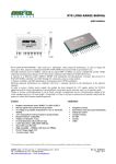
1
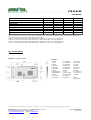
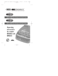
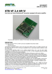
XTR-8LR100 --------------------------------------------------------------------------------------------------------------------------------------------------- User Manual XTR-8LR100 is an half duplex transceiver based on Semtech (SX1276 chipset) patented “LoRa SSM” modulation technique providing an ultra long range radio communication, high interference immunity, high sensitivity and very low power consumption. Compared to standard modulation techniques, XTR-8LR100 improves up to 20 dB the receiver sensitivity, allowing long distances by using low power in transmission and low consumption, inexpensive power supply circuits and low cost batteries. Transceiver works in 869,4÷869,65MHz (100mW, ver. 8LR100) and 868÷868,6MHz (25mW ver.XXX) European band with possibility to set the channel width . XTR-8LR100 is a radio-modem with UART input interface, working on data packages (max. size 255 bytes). It can handle addressing schemes for point-to-multipoint star networks. Main radio parameters might be set up smoothly via command mode procedure. Operating voltage is 3,3V, current consumption is 17 mA in reception, 115 mA in transmission (+20dBm ERP) or 35 mA (15 dBm ERP). Module is available in tape & reel package for SMD assembling. Size is 37 x 18 x 2,2 mm. Main features Direct transmission or radiomodem mode UART interface with store and foreward mode No encoding or preamble requested AT command mode for set up of parameters HyperTerminal* compatible Channels: 7 max Small form factor (37x18X2,2 mm) UART data rate: 9600, 19200, 115200 bps Emitted power: max 100 mW Sensitivity from -118 to-144 dBm Operating voltage: 3,3V Standard distance: 6000 m Applications Home and building automation Irrigation control Energy monitoring Industrial sensors SCADA Alarms Automatic Meter Reading Le caratteristiche tecniche possono subire variazioni senza preavviso. AUR°EL S.p.A. non si assume la responsabilità di danni causati dall’uso improprio del dispositivo. ------------------------------------------------------------------------------------------------------------------------------------------------------------------AUR°EL S.p.A. Via Foro dei Tigli, 4 - 47015 Modigliana (FC) – ITALY Rev 2.0 11/03/2015 Pag 1 di 20 Tel.: +39.0546.941124 Fax: +39.0546.941660 http://www.aurelwireless.com - email: [email protected] XTR-8LR100 --------------------------------------------------------------------------------------------------------------------------------------------------- User Manual Absolute maximum ratings Operating temperature Storage temperature -20 °C ÷ +70 °C -40 °C ÷ +100 °C Supply voltage Input voltage Output voltage +3,4V -1.0 ÷ Vcc + 0.3V -1.0 ÷ Vcc + 0.3V Technical Characteristics DC Levels Supply voltage pin 1,15. Current consumption (rx mode) Current consumption (tx mode @ +20 dBm) Current consumption (sleep mode) High level voltage in input/output Low level voltage in input/output RF TX Band Emitted power Modulation Channel width -3dB Spurious emissions < 1GHz Spurious emissions > 1GHz Pin 14 ESD protection on contact (61000-4-2) Power on adjacent channel in TX (note 2) RF RX Sensitivity in RX, 125 KHz band (SF:6-10-12) Sensitivity in RX, 62,5 KHz band (SF:6-10-12) Sensitivity in RX, 20,8 KHz band (SF:6-10-12) RF band Adjacent channel selectivity (note 3) Adjacent channel saturation (note 4) Blocking test at ±2MHz (note 5) Blocking test at ±10MHz (note 5) Performance Spreading Factor Coding Rate UART data rate (note 1) Package size Outdoor range Channels Channel space with 20,8KHz BW Timing Min. Typ. Max. Unit 2.4 3.3 17 110 1 3.6 150 2 Vcc 0.3xVcc V mA mA µA V V 20 MHz dBm 90 0.7xVcc 0 17 20,8 869,4÷869,65 19 LORA 62,5 125 -36 -30 8 50 -118 -121 -127 -132 -135 -140 6 50 ≥87 85 85 6 4/5 9600 1 -137 -140 -144 90 94 10 19200 12 4/8 115200 255 6000 1 7 25 KHz dBm dBm KV nW dBm dBm dBm MHz dB dB dB dB bps Byte m n° kHz Le caratteristiche tecniche possono subire variazioni senza preavviso. AUR°EL S.p.A. non si assume la responsabilità di danni causati dall’uso improprio del dispositivo. ------------------------------------------------------------------------------------------------------------------------------------------------------------------AUR°EL S.p.A. Via Foro dei Tigli, 4 - 47015 Modigliana (FC) – ITALY Rev 2.0 11/03/2015 Pag 2 di 20 Tel.: +39.0546.941124 Fax: +39.0546.941660 http://www.aurelwireless.com - email: [email protected] XTR-8LR100 --------------------------------------------------------------------------------------------------------------------------------------------------- User Manual PWRDN → RX TX → RX RX → TX Default value Channel Emitted power (tx) UART data rate (only for data) Bandwidth Spreading Factor TBD ms ms ms TBD TBD (CN2) 869,5 20 115200 62,5 8 MHz dBm Bps KHz Note l: UART data is meant 8,n,1. UART Speed (command S8) is related to data comunication. For command mode communication this set up is not has no effect and it works basically @9600bps Note2: Test carried out according to method described in ETSI EN 300 220-1 V2.4.1 paragraph 7.6 Note3: Test carried out according to method described in ETSI EN 300 220-1 V2.4.1 paragraph 8.3 Note4: Test carried out according to method described in ETSI EN 300 220-1 V2.4.1 paragraph 8.3.4 Note5: Test carried out according to method described in ETSI EN 300 220-1 V2.4.1 paragraph 8.4 Pin out description Picture 1: module pin-out Pin-out 1) GND 2) GND 3) GND 4) AN0(NI) 5) AN1(NI) 6) AN2(NI) 7) GND 8) RESERVED 9) RESERVED 10) +Vcc 11) GND RF 12) GND RF 13) GND RF 14) ANTENNA 15) GND RF 16) GND RF 17) GND RF 18) GND RF 19) RTS 20) CTS 21) RX_UART 22) TX_UART 23) IN4(NI) 24) IN3(NI) 25) IN2(NI) 26) IN1(NI) 27) GND 28) SET_C 29) SET_B 30) SET_A 31) GND 32) OUT2(NI) 33) OUT1(NI) 34) GND *NI:not implemented Le caratteristiche tecniche possono subire variazioni senza preavviso. AUR°EL S.p.A. non si assume la responsabilità di danni causati dall’uso improprio del dispositivo. ------------------------------------------------------------------------------------------------------------------------------------------------------------------AUR°EL S.p.A. Via Foro dei Tigli, 4 - 47015 Modigliana (FC) – ITALY Rev 2.0 11/03/2015 Pag 3 di 20 Tel.: +39.0546.941124 Fax: +39.0546.941660 http://www.aurelwireless.com - email: [email protected] XTR-8LR100 --------------------------------------------------------------------------------------------------------------------------------------------------- User Manual PIN DESCRIPTION TAB: N° Pin Nome 1 GND 2 GND 3 GND 4 AN0 5 AN1 6 AN2 7 GND 8 RESERVED 9 RESERVED 10 +Vcc Descrizione Ground connection Ground connection Ground connection Analog input (ADC cyclical mode) Analog input (ADC cyclical mode) Analog input (ADC cyclical mode) Ground connection Not to be connected Not to be connected Regulated supply voltage 3,3V-500mA. Connect a capacitor 10-100uF very close to the pin and GND. Ground connection 11 12 13 14 15 16 17 18 19 GND RF GND RF GND RF ANTENNA GND RF GND RF GND RF GND RF RTS 20 21 CTS RX_UART Clear to send. Input (not implemented) 22 TX_UART UART output in TTL levels, 1 start bit (0V), 8 data bit e 1 stop bit (3V). Input must be driven in high level logic (3V) 23 24 25 26 27 28 29 30 31 32 33 34 IN4 IN3 IN2 IN1 GND SET_C SET_B SET_A GND OUT2 OUT2 GND Digital input, non implemented yet Ground connection Ground connection 50 ohm impedance for antenna Ground connection Ground connection Ground connection Ground connection Request to send. Output goes high when UART buffer is full or during filling/emptying from radio FIFO. Output goes low when ready to receive data from UART port. UART input in TTL levels, 1 start bit (0V), 8 data bit e 1 stop bit (3V). Input must be driven in high level logic (3V) Digital input, non implemented yet Digital input, non implemented yet Digital input, non implemented yet Ground connection Set operation mode Set operation mode Set operation mode Ground connection Digital output. High when transmit or in test mode receives PONG Digital output. High when transmit or in test mode receives PING Ground connection Tab1: Pin description Le caratteristiche tecniche possono subire variazioni senza preavviso. AUR°EL S.p.A. non si assume la responsabilità di danni causati dall’uso improprio del dispositivo. ------------------------------------------------------------------------------------------------------------------------------------------------------------------AUR°EL S.p.A. Via Foro dei Tigli, 4 - 47015 Modigliana (FC) – ITALY Rev 2.0 11/03/2015 Pag 4 di 20 Tel.: +39.0546.941124 Fax: +39.0546.941660 http://www.aurelwireless.com - email: [email protected] XTR-8LR100 --------------------------------------------------------------------------------------------------------------------------------------------------- User Manual LoRa Modulation: The RF modulator and demodulator uses the spread spectrum radio technique and it's possible to set Chip/Symbol ratio from 128 to 4096, depending on RF sensitivity and flying time desired. Improvement of sensitivity is outstanding compared to standard FSK modulation technique: 7,5 dB with 128 Chip/Symbol value and 20 dB with 4096 Chip/Symbol value. Furthermore it is granted a general improvement of interference immunity, adjacent channel immunity and blocking tests compared to FSK demodulator. The tables herebelow show how to properly set modulation parameters depending on sensitivity and flying time desired. In order to be understood, flying time means the radio channel occupation for data package made of a 8 bytes preamble + 8 bytes payload + CRC. Spreading Factor 6 7 8 9 10 11 12 Bandwidth 125KHz Sensitivity (dBm) Flying time (ms) -118 20 -123 41 -126 82 -129 144 -131 287 -134 495 -137 990 Spreading Factor 6 7 8 9 10 11 12 Bandwidth 62,5KHz Sensitivity (dBm) Flying time (ms) -121 41 -126 82 -129 164 -132 288 -135 577 -137 990 -140 1980 Spreading Factor 6 7 8 9 10 11 12 Bandwidth 20,8KHz Sensitivity (dBm) Flying time (ms) -127 124 -130 246 -134 492 -137 862 -140 1730 -142 2960 -145 5940 Le caratteristiche tecniche possono subire variazioni senza preavviso. AUR°EL S.p.A. non si assume la responsabilità di danni causati dall’uso improprio del dispositivo. ------------------------------------------------------------------------------------------------------------------------------------------------------------------AUR°EL S.p.A. Via Foro dei Tigli, 4 - 47015 Modigliana (FC) – ITALY Rev 2.0 11/03/2015 Pag 5 di 20 Tel.: +39.0546.941124 Fax: +39.0546.941660 http://www.aurelwireless.com - email: [email protected] XTR-8LR100 --------------------------------------------------------------------------------------------------------------------------------------------------- User Manual As you can see sensitivity increases as far as SF value increases and data rate decreases as far as SF increases and Bandwidth decreases. Parameters choice have to be made by assessing at first the bandwidth: if more channels are requested it's mandatory to choose 20,8 KHz BW, otherwise, 62,5 or 125 KHz BW. In this case SF value equals to 8-10 is the best trade-off between RF sensitivity and flying time. Very often in radio control applications, payload is not more than 8-10 bytes and 0,5 sec is a reasonable time for transmission and feedback (ACK) reception. Here below the calculation equations of flight times for packet radio with payloads greater than 8Bytes: 2 SF Tsym = BW EQ1 Tsym: durata di un simbolo in secondi SF: Spreading Factor da 6 a 12 BW: banda del canale radio in Hz (registro S2) (8 × nBytePL ) − (4 × SF ) + 44 ( ) PayloadsymbNb = 8 + ceiling × CR + 4 4 × (SF − 2 ) EQ2 PayloadsymbNb: Payload symbol quantity nBytePL: Payload byte quantity CR: coding rate from 1 to 4 (register S6) Tpachet = (PayloadsymbNb + 12,25) × Tsym EQ3 Tpachet: data packet total timing in seconds 12,25: Simbols quantity used on preamble Data packet frame: XTR-8LR100 is a radio modem working in packet mode and handling addresses for point-to-multipoint networks. Packet has a 255 bytes max length, where 247 bytes are the payload and 7 the addresses. It's made up of: • Preamble: it comprises 8 bytes of variable length depending on data rate, used for synchronization purposes.. • Header: it comprises information related to the payload lengths, Code Rate, and CRC presence of payload 16 bit • Network_ID: every module has got a 4 bytes network ID, editable via AT command. (It’s present only in net modality S10=1) Le caratteristiche tecniche possono subire variazioni senza preavviso. AUR°EL S.p.A. non si assume la responsabilità di danni causati dall’uso improprio del dispositivo. ------------------------------------------------------------------------------------------------------------------------------------------------------------------AUR°EL S.p.A. Via Foro dei Tigli, 4 - 47015 Modigliana (FC) – ITALY Rev 2.0 11/03/2015 Pag 6 di 20 Tel.: +39.0546.941124 Fax: +39.0546.941660 http://www.aurelwireless.com - email: [email protected] XTR-8LR100 --------------------------------------------------------------------------------------------------------------------------------------------------- User Manual • • • • • Sourse Address: Module or Node address from sicht the data packet starts (sender), composed by 2 bytes for a maximum node capability of 65536 nodes each net editable via AT command. (It’s present only in net modality S10=1) Destination Address: 2 bytes destination node address. This address can be changed via AT command. It must be forwarded on serial port before the payload. 0xFF (default) address means a broadcasting message: in this case every node joining the network (same network_ID) receives the message (It’s present only in net modality S10=1) Payload: from 1 to 247 bytes. When received, the message is forwarded to UART output only in case Network_ID and Destination address are corresponding, otherwise it's eliminated. In case of transmission, data coming from UART port are included in payload field. Payload CRC: checksum 2 Bytes In normal TX and RX operations, it is mandatory to set up the 2 addresses needed for network functionality in command mode, then move to NORMAL mode and send/receive data (payload) via UART port. To transmit a radio data packet, User must sent on UART the Destination address before the payload. Data are not yet encryped. Picture 2: Data radio packet frame in NORMAL Mode with addressing In NORMAL mode no network (register S10=0) fields NETWORK ID, SOURCE ID e DESTINATION ADDRESS will not present on radio protocol and 255 bytes payload will be at disposal Picture 3: Data radio packet frame in NORMAL Mode no network Le caratteristiche tecniche possono subire variazioni senza preavviso. AUR°EL S.p.A. non si assume la responsabilità di danni causati dall’uso improprio del dispositivo. ------------------------------------------------------------------------------------------------------------------------------------------------------------------AUR°EL S.p.A. Via Foro dei Tigli, 4 - 47015 Modigliana (FC) – ITALY Rev 2.0 11/03/2015 Pag 7 di 20 Tel.: +39.0546.941124 Fax: +39.0546.941660 http://www.aurelwireless.com - email: [email protected] XTR-8LR100 --------------------------------------------------------------------------------------------------------------------------------------------------- User Manual Operation modes: Device works in 7 states operation modes: 1. SLEEP 2. COMMAND MODE 3. NORMAL 4. TX WAKE UP 5. RX WAKE UP 6. TX ADC WAKE UP 7. TEST MODE 1. Sleep When SET_A, SET_B, SET_C inputs are floating or high level, module enters automatically in sleep state: radio and microcontroller chips are in low power state. It' only allowed the activation of command mode (++++) via UART port. 2. Command Mode Command mode allows the user to set up operating parameters. Configuration occurs via AT commands sent to TX_UART (pin.22) with 9600 bps data rate. Likewise return values are received from RX_UART (pin.21). To enter command mode, from sleep mode send to TX_UART a sequence of 4 ‘+’ ASCII characters in a row (++++) . In order to execute it, it's recommended to use the RS232 or USB port of PC (pay attention to convert phisical levels to 0-3V), connect TX and RX while RTS and CTs are not handled in command mode. Use a program for serial port communication, like Hyperterminal, RealTerm or similar ones, by setting these parameters: data rate: 9600 bps, one start bit, 8 data bit, 1 stop bit, no parity, select CR and LF Send from PC the sequence ++++. If the return value is COMMAND-MODE then communication is ok. When the device is in command mode, it can't send/receive any data to/from/ RF. In command mode the UART data rate is fixed at 9600 bps and any change to S8 register can't affect data rate in command mode. How to quit command mode After 1 minute. from last command sent, module automatically switches to sleep mode. Otherwise, in order to force the exit, send ATCC command: if everything is right you'll get a OK as confirmation. Le caratteristiche tecniche possono subire variazioni senza preavviso. AUR°EL S.p.A. non si assume la responsabilità di danni causati dall’uso improprio del dispositivo. ------------------------------------------------------------------------------------------------------------------------------------------------------------------AUR°EL S.p.A. Via Foro dei Tigli, 4 - 47015 Modigliana (FC) – ITALY Rev 2.0 11/03/2015 Pag 8 di 20 Tel.: +39.0546.941124 Fax: +39.0546.941660 http://www.aurelwireless.com - email: [email protected] XTR-8LR100 --------------------------------------------------------------------------------------------------------------------------------------------------- User Manual AT command list: Commands allow to write and read registers which set the way the module operates. Configuration registers reading and writing occurs by sending the sequence AT followed by command or register name, according to the standard of PSTN modems. Here below you find the list of available commands: in order to use them, please abide by the examples of registers reading and writing shown in next page. AT COMMAND Uppercase characters that come before a command or a register Commands are codes including one or more characters <CR> <LF> Command ends always with <CR> Carriage Return <LF> line feed Register Name Function Values S0 r HW/FW Version It mean the radio module version HW and FW Byte High = HW Version Byte Low = FW Version S1 r/w BAND Operating band frequency 0= 868 – 868,6MHz (NI, availbla in other versions) 1= 869,4 – 869,65MHz (default) S2 r/w BANDWIDTH RF channel bandwidth S3 r/w CHANNEL (note 2) S4 r/w POWER S5 r/w SPREADING FACTOR 0 = 20,8 KHz 1 = 62,5 KHz (default) 2 = 125 KHz Operating radio channel BW 20,8KHz 62,5KHz 0= 869,45MHz NI To apply with limits imposed by EN300 220 1= 869,475MHz NI normative, channeling is viable only with BW 20,8 KHz; for the others BW (62,5 KHz 2= 869,5MHz default e 125 KHz) setting of channel is useless and (default) module will work only on default channel 3= 869,525MHz NI 4= 869,55MHz NI 5= 869,575MHz NI 6= 869,6MHz NI RF power emitted in antenna 0 = NI (nota 1) 1 = NI (nota 1) 2 = +20dBm (default) 3 = NI (nota 1) 4 = NI (nota 1) Spreading factor 6 = 64 (chip/symbol) 7 = 128 8 = 256 (default) 9 = 512 10 = 1024 11 = 2048 12 = 4096 125KHz NI NI default NI NI NI NI Le caratteristiche tecniche possono subire variazioni senza preavviso. AUR°EL S.p.A. non si assume la responsabilità di danni causati dall’uso improprio del dispositivo. ------------------------------------------------------------------------------------------------------------------------------------------------------------------AUR°EL S.p.A. Via Foro dei Tigli, 4 - 47015 Modigliana (FC) – ITALY Rev 2.0 11/03/2015 Pag 9 di 20 Tel.: +39.0546.941124 Fax: +39.0546.941660 http://www.aurelwireless.com - email: [email protected] XTR-8LR100 --------------------------------------------------------------------------------------------------------------------------------------------------- User Manual S6 r/w S7 r/w S8 r/w (note 3) S10 r/w S11 r/w S12 r/w S20 r/w S30 r/w S90 r S91 r/w S92 r/w Error recovery 1 = 4/5 (default) 2 = 4/6 3 = 4/7 4 = 4/8 Adds in rear of payload the RRSI 0 = No RSSI (default) RSSI value (2 bytes) 1 = RSSI in coda al payload ENABLE UART data rate 0 = 9.600 bps UART BPS 1 = 19.200 bps 2 = 115.200 bps (default) 0 = No network(default) Adds on top of payload, the ID NETWORK 1 = network network and Source address ENABLE It sets the device network address (4 Min = 0x00000001 (default) NETWORK bytes) Max = 0xFFFFFFFF ID It sets the device ID or sender (2 Min = 0x0001 (default) SOURCE bytes)start address message Max = 0xFFFF (broadcast) ADDRESS RX CYCLIC It sets the wake up time interval from Min = 10 ms 2 cyclic receptions from 10ms to Max = 6.000 ms TIME 6000ms with steps of 1ms Default = 100 ms (default) It sets the wake up time interval from Min = 1 s ADC 2 cyclic trasmissions Impostazione Max = 65.535 s TX TIME dell’intervallo di risveglio tra 2 Default = 10 s trasmissioni cicliche from 1s to 65536s with steps of 1s. Addressing is activated by default S1 = x (x = value restored) REGISTERS Registers value restores S2 = x STATUS S3 = x …. Sn = x Setted at 1 it stores on register, the 0 = Modified values (r) DEFAULT default values 1 = Default values (r/w) VALUES Ping-Pong radio test mode 0 = Off RADIO 1 = On Tx Master TEST_MODE 2 = On Rx Slave ERROR CODING (note 1) NI means not implemented yet. Command execution doesn't have any effect. (note 2) To apply with limits imposed by EN300 220 normative, channeling is viable only with BW 20,8 KHz; for the others BW (62,5 KHz e 125 KHz) setting of channel is useless and module will work only on default channel (note 3) UART data rate setting (command S8), refers exclusively to data communication. In command mode this setting has no effect and it will work onlt at 9600 bps. Command Name WR WRITE Feature Write registers value to EEPROM CC COMMAND CLOSE Command Mode exit Sx REGISTER NAME Register ID to be read or write Le caratteristiche tecniche possono subire variazioni senza preavviso. AUR°EL S.p.A. non si assume la responsabilità di danni causati dall’uso improprio del dispositivo. ------------------------------------------------------------------------------------------------------------------------------------------------------------------AUR°EL S.p.A. Via Foro dei Tigli, 4 - 47015 Modigliana (FC) – ITALY Rev 2.0 11/03/2015 Pag 10 di 20 Tel.: +39.0546.941124 Fax: +39.0546.941660 http://www.aurelwireless.com - email: [email protected] XTR-8LR100 --------------------------------------------------------------------------------------------------------------------------------------------------- User Manual Return values to commands and operations on registers Positive return: OK<CR><LF> Negative return: <bl> ERROR<CR><LF> Forbidden operation: <bl> NO ACCESS<CR><LF> Command mode exit EXIT<CR><LF> <CR> Carriage Return, ASCII character 13; <LF> Line Feed, ASCII character 10; <bl> ASCII character 32. Readout of a register Syntax: ATSx<CR><LF> [x = 1, ...,16 register to be read] Return : value stored in the register if the command sintax is correct followed by <CR><LF>. Register value is given digit after digit as ASCII characters. Example: ‘16’ is given as the sequence of ASCII characters 0x31,0x36, corresponding to digit ‘1’ and ‘6’. Same procedure must be applied in case of writing a new value in a register. Writing of a register Syntax: ATSx=Y<CR><LF> [x = 2, 3, 4 register to write on, y = value to add] Return: as described in 'Return values' All values stored in the registers will be lost when the module is turned off, unless the changes are saved in microcontroller EEPROM memory by means of the specific command ATWR: in this case the saved values will be active even if the module is turned off and then on. Command to save registers value in EEPROM c Syntax: Return: ATWR<CR><LF> as described in 'Return values' Command to quit command mode Syntax: Return: ATCC<CR><LF> as described in 'Return values' Command mode exit occurs, even without ATCC command, automatically after 10 sec. of idle state, or after the command ATWR 3. Normal Le caratteristiche tecniche possono subire variazioni senza preavviso. AUR°EL S.p.A. non si assume la responsabilità di danni causati dall’uso improprio del dispositivo. ------------------------------------------------------------------------------------------------------------------------------------------------------------------AUR°EL S.p.A. Via Foro dei Tigli, 4 - 47015 Modigliana (FC) – ITALY Rev 2.0 11/03/2015 Pag 11 di 20 Tel.: +39.0546.941124 Fax: +39.0546.941660 http://www.aurelwireless.com - email: [email protected] XTR-8LR100 --------------------------------------------------------------------------------------------------------------------------------------------------- User Manual Enabled by resetting SET_A input and setting (or leaving floating) SET_B and SET_C. Radio chip and microcontroller are ON: transceiver can receive data from RF and/or from UART port. Therefore in this state the transceiver is in receiver mode and switches to transmission mode only if a packet comes from UART port. When a start bit (low logic level, 0V) and a valid payload packet following (at least 1 byte) is detected on RX_UART (pin.21) input , transceivers moves to transmission mode. The way the store & Forward mechanism works is described by couples of sequence operations: Store from UART on unit A /Forward to RF buffer on unit A/ RF TX unit A RF RX unit B/Forward to UART output on unit B [Fig. 4] When no data are detected on pin 21 for a time longer than 3 bytes length (considered at data rate in usage), transceiver stops the storing of data coming from UART port until the packet is completely forewarded to RF buffer. Max packet size is 247 bytes. Data are sent on air only when the UART storage phase is over. Microcontroller checks the incoming packets from radio receiver and enables forwarding to UART output port only in case of valid packets (corrupted packets are eliminated). RTS line is helpful to monitor UART buffer status: it's normally low level and goes high when buffer is full or during emptying of UART buffer towards radio buffer, or when data are sent on TX_UART (pin22) The following diagram explains how RX, TX and RTS and CTS UART lines work: Picture 4: Data transmission from unit A → B, and trasmission of ACK from unit B → A Le caratteristiche tecniche possono subire variazioni senza preavviso. AUR°EL S.p.A. non si assume la responsabilità di danni causati dall’uso improprio del dispositivo. ------------------------------------------------------------------------------------------------------------------------------------------------------------------AUR°EL S.p.A. Via Foro dei Tigli, 4 - 47015 Modigliana (FC) – ITALY Rev 2.0 11/03/2015 Pag 12 di 20 Tel.: +39.0546.941124 Fax: +39.0546.941660 http://www.aurelwireless.com - email: [email protected] XTR-8LR100 --------------------------------------------------------------------------------------------------------------------------------------------------- User Manual As shown in fig. 4, the time interval from start where data is present on pin21 in unit A (RX_UART), to when it forwarded to pin 22 (TX_UART) of unit B, is strictly depending on payload size and UART data rate of both modules. CTS in high logic level forbids to XTR-8LR100 to sent data on pin 22 (TX_UART) In order to grant a proper functionality of the transceiver, it's not allowed to overlap phases: i.e. if unit A is emptying UART buffer to radio buffer, any data incoming from UART port are lost. In order to execute properly the exchange of packet from/to UART port, it's recommended to control the RTS line as go/stop operation signal. Likewise unit B is not allowed to receive data from RF until the previous packet is still to be transmitted through UART port. Using the NORMAL mode with addressing: NORMAL mode allows to work with addressing data packet, so a potential network composed by many devices permit a point-to-point communication, or point-multipoint. From command-mode network function is achievable with ATS10=1 resigter, other registers to be setted are NETWORK ID reg.number S11 and SOURCE ADDRESS S12 (2 bytes) a unique identifier for each device. A wireless network could be composed by 2 to 65536 devices. SOURCE ADDRESS identifies from which device the message starts, DESTINATION ADDRESS identifies who is the device to which the message is meant. From this condition the device forwards on UART the radio data packet received, but only those who have the same NETWORK ID and DESTINATION ADDRESS. When the device transmit the DESTINATION ADDRESS must be applied ever before the payload. In case of point –multipont network, it’s necessary to set up the DESTINATION ADDRESS on FFFF, then all the related devices with same NETWORK ID will receive the payload preceded by 0xFFFF. No automatic messages ACK is provided. As an example here below a communication between device 1 and 2 on network A for a message “provalink” Step 1 – from UART to XTR-8LR100 Address: 0x0002 Payload: provalink Step 2 – RF Transmission Node 0x0001 XTR-8LR100 Node Step 3 - from XTR-8LR100 to UART 0x0002 XTR-8LR100 Address: 0x0001 Payload: provalink Picture 5: TX-RX diagram of “provalink” message from node 1 to node 2 Le caratteristiche tecniche possono subire variazioni senza preavviso. AUR°EL S.p.A. non si assume la responsabilità di danni causati dall’uso improprio del dispositivo. ------------------------------------------------------------------------------------------------------------------------------------------------------------------AUR°EL S.p.A. Via Foro dei Tigli, 4 - 47015 Modigliana (FC) – ITALY Rev 2.0 11/03/2015 Pag 13 di 20 Tel.: +39.0546.941124 Fax: +39.0546.941660 http://www.aurelwireless.com - email: [email protected] XTR-8LR100 --------------------------------------------------------------------------------------------------------------------------------------------------- User Manual Hereinafter are described necessary operations to realize the example on picture 5 From command-mode of device 1, send the following AT command string: Commands ++++ ATS10=1<CR><LF> ATS11=0x0000000A<CR><LF> ATS12=0x0001<CR><LF> ATWR Answer OK<CR><LF> OK<CR><LF> OK<CR><LF> OK<CR><LF> OK<CR><LF> Note Command-mode enters Network mode activates Assigns network address “A” Assigns device address “1” Save and exit Node 1 has been set in NORMAL Mode with addressing, NETWORK ID = A and SOURCE ADDRESS = 1. ATWR stores new settings on Eprom and brings back the device on SLEEP From command-mode of device 2, send the following AT command string: Commands ++++ ATS10=1<CR><LF> ATS11=0x0000000A<CR><LF> ATS12=0x0002<CR><LF> ATWR Answer OK<CR><LF> OK<CR><LF> OK<CR><LF> OK<CR><LF> OK<CR><LF> Note Command-mode enters Network mode activates Assigns network address “A” Assigns device address “2” Save and exit As per node 1 Commands string is repeated excluding command ATS12 that assigns device address SORUCE ADDRESS = 2 Close SET_A to GND (normal Mode) on both devices and forwards on RX_UART line of device 1 string “02provalink”. Device 1 sends the message via radio. Only the device called “2” will forward on its own TX_UART line “01provalink” message Same as mentioned in the above example, addressing method is obtained placing ahead to the payload, in this case “provalink” the receiver address. Listening device “2” will receive the payload preceded by the sender address. 4. TX Wake up Same as the NORMAL mode but with a data packet RF completed by a long preamble settable from command ATS20=X (X means from 10 to 6000 ms) in order to allow the wake up and the receiving from RX WAKE UP mode devices. This function is viable connecting input SET_B to GND and left open or connected to +V SET_A and SET_C Complementary modality to Rx Wake UP, it is recommended to set the S20 register with the same value. NOTE: RX WAKE UP AND TC WAKE UP do not provide the transmission of ACK automatically. It is possible deploy and ACK from the user side Le caratteristiche tecniche possono subire variazioni senza preavviso. AUR°EL S.p.A. non si assume la responsabilità di danni causati dall’uso improprio del dispositivo. ------------------------------------------------------------------------------------------------------------------------------------------------------------------AUR°EL S.p.A. Via Foro dei Tigli, 4 - 47015 Modigliana (FC) – ITALY Rev 2.0 11/03/2015 Pag 14 di 20 Tel.: +39.0546.941124 Fax: +39.0546.941660 http://www.aurelwireless.com - email: [email protected] XTR-8LR100 --------------------------------------------------------------------------------------------------------------------------------------------------- User Manual 5. RX Wake up It comes in RX wake up when connecting inputs SET_A and SET_B to GND and keep open or connected to +V SET_C line. RX wake up is useful for low consumption applications where an auto awakening is required, allowing to choose the on-off loop fit for wanted consumption. Device is normally in sleep mode with average consumption of 1uA, and command ATS20=X (where X is ms from 10 to 6000 in steps of 1ms) permits to drive the setting. When the time S20 is over, it comes in RX searching for a valid preamble, in order to complete the data packet receiving and repeat the cycle. If RX does not found a valid preamble, it remains on RX for 3 symbols and when they expire, goes back to sleep. RX ON status time out it is a variable purpose of Spreading Factor (SF) and bandwidth computable as follow: 2 SF Ton( RX ) = 3 × BW EQ4 Where: Ton(RX): Receiver turn on time MAX in seconds SF: Spreading Factor from 6 to 12 from S5 register BW: Bandwidth, in (Hz) from S5 register In order to communicate with RX wake up devices is necessary use XTR-8LR100 in TX wake up mode, programmed with similar working parameters. Only in this case preamble emitted will have adequate length to be intercepted. 6. Tx ADC WAKE UP Useful for battery powered application who permits to join up to 3 sensors to ADC inputs and and transmit the value at predetermined cycles independently without using interfaces and external intelligence. This function is possible connecting inputs SET_A and SET_C to GND and keep open or connected to +V SET_B line. Analog inputs used are: AN0 (pin4), AN1 (pin5) e AN3 (pin6) they allows analog signals from 0 to Vcc 12 bit resolution. Device is normally in sleep mode, and it awake with timing fit to command ATS30=X (where X is in second from 1 to 65536). It red analog sensors value, transumi the status of ADC, goes to sleep and repeat the cycle. Device The device operates only in network mode with broadcast destination address (all FFFF), Receiver with same ID network submits on UART ADC values preceded by SOURCE ADDRESS (0xFFF) Le caratteristiche tecniche possono subire variazioni senza preavviso. AUR°EL S.p.A. non si assume la responsabilità di danni causati dall’uso improprio del dispositivo. ------------------------------------------------------------------------------------------------------------------------------------------------------------------AUR°EL S.p.A. Via Foro dei Tigli, 4 - 47015 Modigliana (FC) – ITALY Rev 2.0 11/03/2015 Pag 15 di 20 Tel.: +39.0546.941124 Fax: +39.0546.941660 http://www.aurelwireless.com - email: [email protected] XTR-8LR100 --------------------------------------------------------------------------------------------------------------------------------------------------- User Manual 7. Test Mode It's an operation mode which allows the user to test seamlessly the radio link performance. It is triggered by driving input SET_C to low level and setting (or leaving floating) SET_A and SET_B pins. This mode allows to connect two devices as Master and Slave. The former sends 4 ASCII characters "PING" and in case the latter receives, it will answer with an ACK value of 4 ASCII characters "PONG". Communication is reported by outputs: OUT_1 (pin 33) goes high when Master sends or Slave receive a "PING" OU2_1 (pin 32) goes high when Master receive or Slave sends a "PONG" The selection between Master/Slave configuration is made through ATS92 command: 0 = disabled feature 1 = module set as Master 2 = module set as Slave When you have finished test in Test Mode before returning to work in other modes of operation, it is essential to disable the Test with the command ATS92 = 0. Application schematic: Module connection in NORMAL mode is very easy. TX, RX and configuration pins are handled via asynchronous serial interface. CTS line is not implemented yet. Module works always in receive mode. Switching from RX to TX mode is triggered automatically when the first data byte comes to input pin 21 (RX_UART). Le caratteristiche tecniche possono subire variazioni senza preavviso. AUR°EL S.p.A. non si assume la responsabilità di danni causati dall’uso improprio del dispositivo. ------------------------------------------------------------------------------------------------------------------------------------------------------------------AUR°EL S.p.A. Via Foro dei Tigli, 4 - 47015 Modigliana (FC) – ITALY Rev 2.0 11/03/2015 Pag 16 di 20 Tel.: +39.0546.941124 Fax: +39.0546.941660 http://www.aurelwireless.com - email: [email protected] XTR-8LR100 --------------------------------------------------------------------------------------------------------------------------------------------------- User Manual Picture 6: Application schematic Le caratteristiche tecniche possono subire variazioni senza preavviso. AUR°EL S.p.A. non si assume la responsabilità di danni causati dall’uso improprio del dispositivo. ------------------------------------------------------------------------------------------------------------------------------------------------------------------AUR°EL S.p.A. Via Foro dei Tigli, 4 - 47015 Modigliana (FC) – ITALY Rev 2.0 11/03/2015 Pag 17 di 20 Tel.: +39.0546.941124 Fax: +39.0546.941660 http://www.aurelwireless.com - email: [email protected] XTR-8LR100 --------------------------------------------------------------------------------------------------------------------------------------------------- User Manual Device usage In order to obtain the performances described in the technical specifications and to comply with the operating conditions which characterize the Certification, the transmitter should be mounted on a printed circuit taking into account the following: Power Supply: 1. XTR-8LR100 must be supplied from very low voltage safety source protected against the short circuits. Maximum voltage variations allowed: 2.4 ÷ 3.6 V. However it is preferable to maintain a stable voltage to a predetermined value in the range of voltage as specified above, using a voltage regulator "Fast transient response" 2. Decoupling, next to the transmitter, with a ceramic capacitor of minimum 100nF. 3. Connect electrolytic capacitor 220uF, low ESR, close to the pin 10 (+Vcc). Pin interface: Put a capacity of 22-100pF close to the corresponding pins of signal connection, connected between them and the ground plane. The capacitance value varies according to the pin of the module, so please follow to the electrical schematic of Figure 5 and the lay-out of figure 6. Ground: The mass must surround at the best the welding area of the module and must also be realized in the lower face in order to obtain the optimal result, with the through holes connecting the two ground planes. Antenna: Connect pin 2 (antenna) to the coaxial connector or antenna, with microstrip constant impedance of 50R, width 3.2 mm for PCB with thickness 1.6 mm and 1.6 mm for PCB with thickness 1mm. (see Figure 6) The antenna is a typical rigid copper wire (insulated or not) of 8cm length and cross-section of 0.5 mm ² placed vertically to the ground plane. Other placements of antenna (bend, spiral) will work but performance are not predictable. As an alternative to connect the module to an external antenna, connect an SMA connector into PCB using microstrip 50 (see figure below). The proposed lay-out below, for example, shows the connections of signals and power supply on the top and a ground plane on the bottom side of the extended PCB that surrounds the radio module. The cross-link antenna impedance 50R is 3.2 mm wide, specifically, calculated for double-sided Fr-4 epoxy glass 1.6 mm thick. The pin 1 of the power supply, is connect to the power supply with 2mm wide track. A 220uF electrolytic capacitor must be placed nearby. The pins of the input output signals of the module are connected to the ceramic capacitors from 22 to 100pF, places close by the same. Le caratteristiche tecniche possono subire variazioni senza preavviso. AUR°EL S.p.A. non si assume la responsabilità di danni causati dall’uso improprio del dispositivo. ------------------------------------------------------------------------------------------------------------------------------------------------------------------AUR°EL S.p.A. Via Foro dei Tigli, 4 - 47015 Modigliana (FC) – ITALY Rev 2.0 11/03/2015 Pag 18 di 20 Tel.: +39.0546.941124 Fax: +39.0546.941660 http://www.aurelwireless.com - email: [email protected] XTR-8LR100 --------------------------------------------------------------------------------------------------------------------------------------------------- User Manual Picture 7: Example of lay-out, the connection tracks on PCB on the top side and ground plane in the button side Reference Rules XTR-8LR100 transceiver is compliant with the European set of rules EN 300 220 V2.4.1 (2012-05), and EN 301 489-3 V1.5.1 (2012-07). Tests has been performed through transmissions of Pseudo Code Random at 500bps(CEPT 70-03). The occupancy of bandwidth has been performed through transmissions of Pseudo Code Random at 500bps. In addition, the product has been tested according to EN 60950 and it can be utilized inside a special insulated housing that assures the compliance with the above mentioned rules. The transceiver must be operated from a very low voltage source, safety protected against short circuits. The usage of the transceiver is foreseen inside housings that assure the overcoming of the rule EN 61000-4-2 not directly applicable to the module itself. In particular, it is the user's care the insulation of the external antenna connection and antenna itself since the RF output of the receiver is not able to directly bear the electrostatic charges foreseen by the above mentioned rule. Le caratteristiche tecniche possono subire variazioni senza preavviso. AUR°EL S.p.A. non si assume la responsabilità di danni causati dall’uso improprio del dispositivo. ------------------------------------------------------------------------------------------------------------------------------------------------------------------AUR°EL S.p.A. Via Foro dei Tigli, 4 - 47015 Modigliana (FC) – ITALY Rev 2.0 11/03/2015 Pag 19 di 20 Tel.: +39.0546.941124 Fax: +39.0546.941660 http://www.aurelwireless.com - email: [email protected] XTR-8LR100 --------------------------------------------------------------------------------------------------------------------------------------------------- User Manual CEPT 70-03 XTR-8LR100 transceiver operates in a harmonized frequency band and therefore, in order to comply with local regulations, the device must be used on the time scale with maximum duty-cycle time 10% (equivalent to 6 to 60 minutes of usage ). Version: Data rilascio 11/03/2015 Revisione manuale d’uso 1.0 2.0 Firmware Variazioni rispetto alla precedente revisione corrispondente 0100 Primo rilascio 0107 Inserite fig.3,4,5,6 comandi AT, Normal con indir. Modalità 4,5,6, EQ. Da 1 a 4, Le caratteristiche tecniche possono subire variazioni senza preavviso. AUR°EL S.p.A. non si assume la responsabilità di danni causati dall’uso improprio del dispositivo. ------------------------------------------------------------------------------------------------------------------------------------------------------------------AUR°EL S.p.A. Via Foro dei Tigli, 4 - 47015 Modigliana (FC) – ITALY Rev 2.0 11/03/2015 Pag 20 di 20 Tel.: +39.0546.941124 Fax: +39.0546.941660 http://www.aurelwireless.com - email: [email protected]