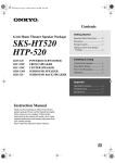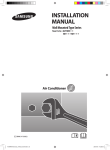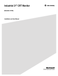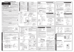
1
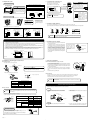
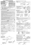
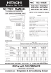
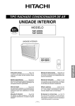
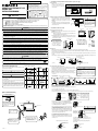
In the case of making a hole on the wall.
Drain hose
make lower
than center of
the hole.
Tools Needed For Installation Work
• Read the safety precautions carefully before operating the unit.
• The contents of this section are vital to ensure safety. Please pay special attention to the following sign.
WARNING .... Incorrect methods of installation may cause death or serious injury.
CAUTION ...... Improper installation may result in serious consequence.
Make sure to connect earth line.
This sign in the figures indicates prohibition.
Be sure that the unit operates in proper condition after installation. Explain to customer the proper watt of operating the unit as
described in the user’s guide.
WARNING
• Please request your sales agent or qualified technician to install your unit. Water leakage, short circuit or fire may occur if you do
the installation work yourself.
• Please observe the instructions stated in the installation manual during the process of installation. Improper installation may
cause water leakage, electric shock and fire.
• Make sure that the units are mounted at locations which are able to provide full support to the weight of the units. If not, the units
may collapse and impose danger.
• Observe the rules and regulations of the electrical installation and the methods described in the installation manual when dealing
with the electrical work. Use wire which are approved official in your country. A short circuit and fire may occur due to the use of
low quality wire or improper work.
• Be sure to use the specified wire for connecting the indoor and outdoor units. Please ensure that the connections are tight after
the conductors of the wire are inserted into the terminals. Improper insertion and loose contact may cause over-heating and fire.
• Please use the specified components for installation work. Otherwise, the unit may collapse or water leakage, electric shock and
fire may occur.
• When installing or transferring an air conditioner to another location, make sure that air other than the specified refrigerant
(R410A) does not enter the refrigeration cycle. If other air should enter, the pressure level of the refrigeration cycle may increase
abnormally which could result in a rupture and injury.
• Be sure to use the specified piping set for R410A. Otherwise, this may result in broken copper pipes or faults.
• When installing or removing an air conditioner, do not allow air or moisture to remain in the refrigeration cycle. Otherwise,
pressure in the refrigeration cycle may become abnormally high so that a rupture may be caused.
• Be sure to ventilate fully if a refrigerant gas leak while at work. If the refrigerant gas comes into contact with fire, a poisonous gas
may occur.
• After completion of installation work, check to make sure that there is no refrigeration gas leakage. If the refrigerant gas leaks into
the room, coming into contact with fire in the fan-driven heater, space heater, etc., a poisonous gas may occur.
• Unauthorized modifications to the air conditioner may be dangerous. If a breakdown occurs please call a qualified air conditioner
technician or electrician. Improper repairs may result in water leakage, electric shock and fire, etc.
• Be sure to connect the earth line from the power supply wire to the outdoor unit and between the outdoor and indoor
unit. Improper earthing may cause electric shock.
65mm
1.2 Wall penetration and installation of protection pipe
Indoor
• Drill a ø65mm hole on wall which is slightly tilted
towards the outdoor side. Drill the wall at a small
angle.
• Cut the protection pipe according to the wall
thickness.
• Empty gap in the sleeve of protection pipe should be
completely sealed with putty to avoid dripping of rain
water into the room.
Outdoor
Seal with
putty
Seal with
putty
Protection
pipe
2. Installation of the indoor unit
2.1 How to remove the front cover
Be sure that the wire is not in
contact with any metal in the
wall. Please use the protection
pipe as wire passing through
the hollow part of the wall so
as to prevent the possibility of
damaged by mouse.
Screw (2 pieces)
(1) Remove the front panel (refer to instructions on the reverse of this
sheet).
(2) Remove the front cover.
• Remove the two bottom screws and two top screws. Pull the front
cover approximately 30mm toward you.
* When attaching the front cover, follow the above procedure in reverse
order. Make sure the hooks at the front cover top surface are securely
inserted into the cabinet.
10mm pitch groove
If there is a baseboard
Front cover
Cabinet
Screw (2 pieces)
For sideways piping
Cabinet
• For right or left sideways
piping, cut the cabinet’s
bushing with a plastic cutter
or similar tool and use a file
for an attractive finish.
Baseboard
• If the baseboard is
5~15mm in thickness and
70~130mm in height, cut
the pipe bushing to
conform to the baseboard.
CAUTION
Sleeve of
protection pipe
WALL
130
SAFETY PRECAUTION
In the case of making a hole on the floor.
65mm
70
(Mark is exclusive use tool for R410A) • ª· Screwdriver
• Measuring Tape • Knife • Saw • ø65mm Power
Drill • Hexagonal Wrench Key (
4mm) • Wrench
(14,17,22,26,27mm)
Gas leakage Detector • Pipe
Cutter • Putty • Vinyl Tape • Pliers • Flare Tool
Vacuum Pump Adapter
Manifold Valve
Charge
Hose
Vacuum Pump
RAF-25NH4
RAF-50NH4
MODEL
Hole Position
80~100mm
INVERTER SYSTEM MULTI TYPE
INDOOR UNIT
INSTALLATION MANUAL
• Make a hole on the wall such the
position as shown below, in order
to keep the flow for condensed
water smooth.
2~5mm
• Carefully read through the procedures of proper installation
before starting installation work.
• The sales agent should inform customers regarding the
correct operation of installation.
• Explanation for outdoor unit is in the “How To Use”
(Instruction Manual) that packed with outdoor unit.
1. Installation of wall penetration and installation of protection pipe
1.1 Hole position
40mm or less
FOR SERVICE PERSONNEL ONLY
Bushing
(2 pieces
on each
side)
5
15
2.2 Drain pipe
• Make sure drain pipe slopes downward so that drain flows smoothly without being trapped in the middle.
• The drain hose (connecting port outer diameter: 16mm or 20mm, length: 600mm) is included in the indoor unit. Prepare a drain
pipe as shown in the following figure.
• To prevent condensation, the indoor drain pipe should be covered with heat insulation material with a thickness of more than
10mm.
• After piping is completed, check to make sure that drain discharges smoothly. Seal the drain pipe tightly with tape to keep dirt out.
CAUTION
Front view
• A circuit breaker must be installed in the house distribution box for the direct connected power supply wire to the outdoor unit. In
case of other installations a main switch with a contact gap or more than 3mm has to be installed. Without a circuit breaker, the
danger of electric shock exists.
• Do not install the unit near a location where there is flammable gas. The outdoor unit may catch fire if flammable
gas leaks around it. Piping shall be suitable supported with a maximum spacing of 1m between the supports.
Make sure the drain hose
slopes downward.
Right side view
Connecting section
64
Drain hose
600
2.3 Connecting the pipe to indoor unit
Insulator
8
2
4
Before piping.
Screw for Overturn
Prevention
1
30
9
2
(4.0 × 34)
5
Screw for holder of
Remote Controller
• In the case of make
a hole on the floor. • In the case of make a hole on the wall.
(t3 × 160 × 600)
(4.1 × 32)
Holder for Remote
Controller
1
above 380
After piping.
1
(3.1 × 16)
Top view
(20 × 30 × 300)
Front view
Large pipe
0
R8
Wall
0
R6
Floor
0
(Unit: mm)
Small pipe
Right side view
0
R8
Floor
170
Insulator
2
• Sideways piping
Wall
Screw for Overturn
Prevention
40mm or less
3
1
For sideways piping, do not install the drain hose
sideways. Connect the drain hose so that it comes
out directly.
Sideways installation of the drain hose will prevent it
from sloping downward, causing water leakage. To
avoid dripping, make sure to pass the drain hose
under the pipe.
170
7
2
WARNING
130
Binder
Remote
Controller
30
• No nearby heat source and no obstruction near the air outlet
is allowed.
• The clearance distances from top, right and left are specified
in figure below.
• The location must be convenient for water drainage and pipe
connection with the outdoor unit.
• To avoid interference from noise, please place the unit and
its remote controller at least 1m from the radio and television.
• To avoid any error in signal transmission from the remote
controller, please put the controller far away from highfrequency machines and high-power wireless systems.
1
2
CAUTION
2
• Draw in the pipes through the hole of the wall or the floor to indoor.
• Arrange the pipe shown below. In the case that large pipe and small
pipe arrange to make in front and behind.
• The indoor piping should be insulated with the enclosed insulation
pipe.
• The pipe should first be cut longer than the length shown below.
• The excess section of the pipe should be cut off during pipe
connection.
30
• The unit should be mounted at stable, non-vibratory location
which can provide full support to the unit.
AAA size
6 Battery
210
Flare Insulator
1
WARNING
Qty
40mm or less
Item
Wall
No.
Wall
Names of Indoor Components
(Please note the following matters and obtain permission from
customer before installation.)
Drain pipe (procure locally)
30
(Unit: mm)
250
THE CHOICE OF MOUNTING SITE
124
104
210
• Please ensure smooth flow of water when installing the drain hose.
• An IEC approved power cord should be used. Power cord type: NYM.
• Remove PIPE SUPPORT 1 and PIPE SUPPORT 2.
• Insert the drain hose into the hole in the wall.
• Winding insulation pipe for drain hose and taping 4 or 5 places to fix.
• Connect the pipe to the Indoor unit.
• After completing the piping connection, cover the connector with the insulator.
• Connect the cord (follow instructions in the section “5. Connection of the connecting cord” on the reverse of this sheet).
[Indoor unit installation]
2 Binder
PIPE SUPPORT 1
1 Flare
insulator
Direction of Piping
PIPE SUPPORT 2
2 Binder
Wrap flare insulation,
bind top and bottom
flare insulation by
binder. Wrap tape on
flare insulation closely.
Pipe
Above 150mm
Piping configuration may be in six
different directions: direct rear piping,
left and right downward piping, left and
right sideways piping, and sideways
piping from the rear.
• Since there is some space between PIPE SUPPORT 2 and
the pipe, affix the insulator 0 to the PIPE SUPPORT 2.
As shown in the figure on the right, affix the insulator 0
to the PIPE SUPPORT 2 to sandwich it.
Above 200mm
Above 100mm
• After connecting the pipes and connecting cord, be sure to
screw PIPE SUPPORT 1, PIPE SUPPORT 2 tightly and fix
the pipes and connecting cord.
• Position the easy-to-attach side of PIPE SUPPORT 2 (after
aligning it with the pipe) to face the front and secure it with
a screw. (Be sure to install PIPE SUPPORT 2 to prevent
rodents from entering the indoor unit.)
Be sure to completely
seal any gap with
putty.
Drain pipe
Must be installed separately.
Insulate indoor part of pipe
to prevent condensation.
The indoor piping should be
insulated with the enclosed
insulation pipe. (If the insulator
is insufficient, please use
commercial products.)
7
5
6
• To prevent the pipe connector from contacting the front
cover, push the connector as far as it goes.
• Arrange the connecting cord, pipes and drain hose neatly
and store them in the bottom section of the rear surface of
the indoor unit.
4
Plug
(Procure locally)
Pipe layout of the unit rear surface
Indoor unit rear surface
0 Insulator
When mounting the flare
insulator 1, make sure there is
a space between the insulator
and left of resin part. Otherwise,
may cause water dripping.
PIPE SUPPORT 1
Hook the PIPE
SUPPORT 1 tab
in the square hole.
Screws
PIPE SUPPORT 2
Mount PIPE SUPPORT 2 so that the cylindrical portion of the
drain pan passes through its hole and secure it with screws located
at the right back corner.
Pipe/drain hose layout when passing through the
file in a wall
Connecting cord
Connecting cord
Pipe
Pipe
8 Insulator
< S581 : C >
CAUTION
PIPE SUPPORT 2
8 Insulator
Drain hose
3. Fixing the indoor unit
5. Connection of the connecting cord
Fixing the top of indoor unit
In the case of fixing by the anchor bolt
ø9 rear fixing hole for anchor
bolt or screw of accessory.
572mm
Even if there is space between the
indoor unit and the back wall,
make sure to securely attach the
indoor unit to the wall, ceiling or
floor using wire to prevent it from
falling.
65mm
In the case of fixing by the screw of accessory
WARNING
• Leave some space in the connecting cord for
maintenance purpose and be sure to secure it
with the cord band.
• Secure the connecting cord
along the coated part of the
wire using the cord band. Do
not exert pressure on the wire
as this may cause overheating
or fire.
Connect the
earth cord
C
Green-and-yellow
(ground)
50mm
10mm
25mm
D
After remove the screw
and cover, and put the
connecting cords and fix
the cover with screw.
10mm
Bury the plug into the wall as shown in below to attach
the screw 9. Lift up the indoor unit slightly and hang.
Connecting cord
Detail of cutting the connecting cord
Wall
32mm
Wall
Fixing the base of indoor unit
Connection of the connecting cord
9 Screw
ø4.8mm
Drain hose make lower
than center of the hole.
Bury the ø6 anchor bolt into the wall as shown in below.
Lift up the indoor unit slightly and hang.
WARNING
165mm
40mm or less
420mm
(1) Remove the cover of the electric box.
(2) Connect the connecting cords.
(3) Assemble the cover of electric box.
Plug
(Procure locally)
WARNING
Securely screw in the
connecting cord so that it will not
get loose or disconnect.
• THIS APPLIANCE MUST
BE EARTHED.
Tightening torque reference
value: 1.2 to 1.6 N·m (12 to
16 kgf·cm)
• Fix the base of indoor unit on the floor with 4.1 × 32mm screws. (Right and left)
Connecting
cord
• When fixing the indoor
unit above the ground,
be sure to fix an L-angle
at the bottom to support
it.
WARNING
Be sure to attach screw
3 to prevent the indoor
unit from overturn.
3 Screw
3 Screw
Case 1
Case 2
2. Push plug into the holes.
3 Screw
Indoor unit
ø4.8mm
Bad
1. Drill holes on floor.
Floor
Indoor unit
m
8m
ø4.
Bad
Bad
WARNING
3 Screw
Condensed
water pond
m
32m
Plug
(Procure locally)
Bad
2. Push plug into the holes.
Bending
upwards
32mm
Floor
6. Checking of drawing drain hose
(1) Connect the separate drain hose to the drain hose that is attached to the indoor unit.
(2) For keeping the smooth flowing of condensed water the drain hose should be inclined as shown in figure below.
• To drill holes, either Case 1 or 2 may be used.
1. Drill holes on floor.
Excessive tightening may
damage the interior of the cord
requiring replacement.
Plug
(Procure locally)
CAUTION
Condensed
water pond
Be sure that the hose is
not loosely connected
or bent.
Ditch
Please ensure the smooth flow of condensed water of the Indoor unit during installation.
(Carelessness may result in water leakage.)
(The plug can be secured diagonally with a screw as shown above.)
BUIIT-IN INSTALLATION
1 If upper or lower air outlet is covered with the lattice door, room temperature may not be controlled properly. Therefore, air
outlet must be open as much as possible.
2 If air deflector of upper air outlet is adjusted too much upward, room temperature may not be controlled properly due to the
heat inside the lattice door. Therefore, the deflector must be adjusted to nearly horizontal angle.
3 If signal receiver is covered with the lattice door, signal receiving distance or range (angle) becomes smaller. Therefore,
signal receiver must not be covered with the lattice door.
4 Only the vertical lattice door may be used. Be sure to use a lattice door with an open area ratio of 75% or more. If another
lattice door or one with an open area ratio of less than 75% is used, maximum performance may not be obtained.
5 With a built-in installation, it may take more time to reach the set temperature after the unit is switched on.
Signal receiver
Upper air outlet
Above 150
Lattice door
• The remote controller can be placed in its holder which
is fixed on wall or beam.
• To operate the remote controller at its holder, please
ensure that the unit can receive signal transmitted from
the controller at the place where the holder is to be
fixed. The unit will beep when signal is received from
the remote controller. The signal transmission is weaken
by the fluorescent light. Therefore, during the installation
of the remote control holder, please switch on the light,
even during day time, to determine the mounting location
of the holder.
The controller must be
hooked onto the hook at
the lower par t of the
holder. Push in the
remote controller in the
direction as shown in
figure below.
Screw (2 pieces)
Holder for Remote
Controller
Remote controller
Above 200
Above 100
(Unit: mm)
7. Installation of remote controller
Lower air outlet
Below 20
Air conditioner
4. Installation of refrigerating pipes and air removal
4.1 Preparation of pipe
8. Final stage of installation
8.1 Insulation and maintenance of pipe connection
• Use a pipe cutter to cut the copper pipe.
Trimming tool
CAUTION
Copper pipe
• Jagged edge will cause leakage.
• Point the side to be trimmed downwards during trimming to
prevent copper chips from entering the pipe.
OUTSIDE
• The connected terminals should be completed sealed with heat insulator
and then tied up with rubber strap.
• Please tie the pipe and power line together with vinyl tape as shown in
the figure showing the installation of Indoor and Outdoor units. Then fix
their position with holders.
• To enhance the heat insulation and to prevent water condensation,
please cover the outdoor part of the drain hose and pipe with insulation
pipe.
• Completely seal any gap with putty.
INSIDE
Sleeve of
protection pipe
Putty
Putty
• Before flaring, please put on the flare nut.
Die
• Please use exclusive tool.
A
Die
8.2 Operation test
• Please ensure that the air conditioner is in normal operating condition during the operation test.
• Explain to your customer the proper operation procedures as described in the user’s manual.
• If the indoor unit does not operate, check to see that the connections are correct.
Copper pipe
CAUTION
Outer Diameter (ø)
Trial run should be conducted on one unit at a time to check for incorrect wiring of
connecting cord.
A (mm) Rigid Flaring Tool
For R410A tool
For R22 tool
6.35 (1/4")
0 – 0.5
1.0
9.52 (3/8")
0 – 0.5
1.0
12.7 (1/2")
0 – 0.5
1.0
How to install and remove the front panel
• Be sure to use both hands to grasp the front panel when removing it or attaching it.
• The front panel may be installed up or down to suit user preference.
4.2 Pipe connection
Removing
CAUTION
In case of removing flare nut of a indoor unit, first remove a nut of small diameter
side, or a seal cap of big diameter side will fly out. Free from water into the piping
when working.
1 Press the hook found at the tip of the resin band installed
inside the front panel’s right section to remove the resin
band.
• Please be careful when bending the copper pipe.
• Screw in manually while adjusting the center. After that, use a torque wrench to tighten the connection.
2 Pull the front panel down toward you and once fully open,
pull it to remove.
Front cover
Resin band
Flare nut
Small diameter side
Wrench
Torque
wrench
Large diameter side
Small diameter side
Valve head
cap
Large diameter side
Valve core cap
Gas leakage inspection
Please use gas leakage detector to check if leakage occurs at
connection of flare nut as shown on the right.
If gas leakage occurs, further tighten the connection to stop leakage.
(Use the detector provided for R410A.)
< S581 : C >
Outer diameter
of pipe (ø)
Torque N·m
(kgf·cm)
6.35 (1/4")
13.7 – 18.6 (140 – 190)
9.52 (3/8")
34.3 – 44.1 (350 – 450)
12.7 (1/2")
44.1 – 53.9 (450 – 550)
6.35 (1/4")
19.6 – 24.5 (200 – 250)
9.52 (3/8")
19.6 – 24.5 (200 – 250)
12.7 (1/2")
29.4 – 34.3 (300 – 350)
12.3 – 15.7 (125 – 160)
Hook
Resin band
Front panel
Attaching
1 Attach three front panel bearings to the axis of the front
cover.
2 Insert the tip of the resin band into the hole of the
protrusion inside the right section of the front panel.