1
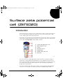
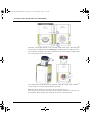
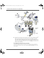
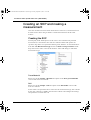
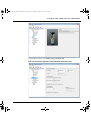
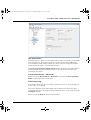
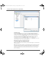
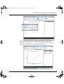
Surface Zeta Potential Cell (Man0483-1.0).book Page i Friday, September 2, 2011 10:31 AM Surface Zeta Potential Cell (ZEN1020) MAN0483 Issue 1.0 September 2011 English Surface Zeta Potential Cell (Man0483-1.0).book Page ii Friday, September 2, 2011 10:31 AM Copyright © Malvern Instruments Ltd. 2011 Malvern Instruments makes every effort to ensure that this document is correct. However, due to Malvern Instruments’ policy of continual product development we are unable to guarantee the accuracy of this, or any other document after the date of publication. We therefore disclaim all liability for any changes, errors or omissions after the date of publication. No reproduction or transmission of any part of this publication is allowed without the express written permission of Malvern Instruments Ltd. Head office: Malvern Instruments Ltd. Enigma Business Park, Grovewood Road, Malvern, Worcestershire WR14 1XZ United Kingdom. Tel + [44] (0)1684-892456 Fax + [44] (0)1684-892789 www.malvern.com Zetasizer is a registered trademark in the UK and/or other countries, and is owned by Malvern Instruments Ltd. Malvern and the green "hills" logo are registered trademarks in the UK and/or other countries, and is owned by Malvern Instruments Ltd. Windows®is a registered trademark of the Microsoft Corporation. Printed in England Surface Zeta Potential Cell (Man0483-1.0).book Page 1 Friday, September 2, 2011 10:31 AM Surface zeta potential cell (ZEN1020) Introduction This document gives a brief overview of the Zetasizer Nano cell for measuring surface zeta potential. It primarily describes how to use, insert and clean the cell to ensure reliable and consistent measurements. The surface zeta potential cell is intended for the measurement of the zeta potential at the surface of a flat material in an aqueous environment. The cell is a dip cell type device that is incompatible with the MPT-2 titrator. Cell cap and adjustment screw White alignment mark Cuvette Electrical contacts Sample barrel Sample holder and screw Electrodes ill 8688 The cell consists of a height adjustable sample barrel , in which the sample is glued onto a sample holder and held between two palladium electrodes . A series of Zeta potential measurements are then performed in a conventional cuvette , with the measurement position within the cell controlled by adjusting the height of the sample barrel. The cell is supplied with a kit of parts: Surface zeta potential cell with palladium electrodes, a 12-well plate for storing the samples, 10 PEEK sample holders, a Surface Zeta Potential Cell Page 1 Surface Zeta Potential Cell (Man0483-1.0).book Page 2 Friday, September 2, 2011 10:31 AM Surface zeta potential cell (ZEN1020) screwdriver for cell tightening, a pair of forceps for sample handling, a cell height alignment tool and a sample holder for gluing the sample to. Measurement technique A surface zeta potential measurement consists of attaching a sample to a mount or holder that is then held in place between two electrodes. The sample is then immersed in an appropriate aqueous solution, containing tracer particles. The apparent tracer mobility is now measured at a number of different distances from the sample surface. The electro-osmotic flow at the sample surface will tend to fall off with increasing distance hence; close to the surface the tracer mobility will be dominated by the electro-osmotic surface flow, while at distances further from the surface it will be dominated by the electrophoretic motion of the tracer itself. The graph below shows a typical plot of reported zeta displacement from the surface. The zeta potential at the surface is then calculated by extrapolating the graph to zero displacement and applying the following formula; Surface zeta potential = ill 8694 – intercept + tracer zeta potential where the tracer zeta potential is recorded far from the wall, where the electroosmotic flow can be taken as zero. In the displacement graph above, the blue circles represent the reported zeta potential of the tracer particles, while the red squares represent the zeta potential Page 2 MAN 0483 Surface Zeta Potential Cell (Man0483-1.0).book Page 3 Friday, September 2, 2011 10:31 AM Surface zeta potential cell (ZEN1020) of the tracer particles measured far from the sample surface and also independent from any electro-osmotic effects. Measurement preparation Before a measurement can be performed the cell must first be loaded onto the sample holder and then attached to the cell. The complete cell is then inserted into a standard cuvette and placed into the instrument. These following operations are described in the next sections; once these are complete the measurement can be performed: Loading the Surface zeta potential cell with sample. Inserting the Surface zeta potential cell into the instrument. Loading the Surface zeta potential cell The surface zeta potential cell is loaded with a sample as described below: Note Take care not to damage the sample surface during attachment to the sample holder. The sample to be measured should be cut into rectangular pieces no larger than 7mm x 4mm (LxW) and no more than 1.5mm thick (H). ill 8689 Surface Zeta Potential Cell Page 3 Surface Zeta Potential Cell (Man0483-1.0).book Page 4 Friday, September 2, 2011 10:31 AM Surface zeta potential cell (ZEN1020) The sample is then attached to the sample holder using an appropriate adhesive such as AralditeTM (refer to note overleaf for guidelines on glue selection). A sample gluing tool is provided to hold the sample holder during the gluing process. Ensure the sample is placed squarely onto the sample holder and not at an angle. The sample should be perpendicular to the electrodes, once inserted into the barrel. There should be no large gaps between the electrodes and sample (≤200μm). Wait until the sample has set in place, then load onto the cell using the supplied forceps and screw the holder into place. Note The glue used should be selected beforehand and be compatible with the experimental design. It should be capable of attaching to both the sample and the holder, and it should not be soluble in the selected medium, so that the sample is securely held in place for the duration of the experiment. Inserting the Surface zeta potential cell The insertion of the Surface zeta potential cell into the Zetasizer Nano is done in three stages. First a coarse alignment is performed where the cell has to be aligned to a zero position with respect to the instrument laser - this is initially done using a height alignment tool supplied with the cell. Secondly the cell is inserted into the cuvette, which is then added into the instrument. Thirdly a fine alignment is performed using the count rate meter in the application software. Once these stages are complete a measurement can be performed. Zeroing the cell height position - Coarse alignment Once the sample holder is in place, the surface of the sample must be aligned to a zero height position with respect to the instrument laser, using the height alignment tool. The surface is aligned to a zeroing target etched on the windows of the tool. There are two zeroing targets, one on the front plate, and one on the back. Hold the alignment tool so that the centre of the two targets coincide, to avoid a parallax error. Page 4 MAN 0483 Surface Zeta Potential Cell (Man0483-1.0).book Page 5 Friday, September 2, 2011 10:31 AM Surface zeta potential cell (ZEN1020) ill 8690 Insert the cell assembly into the tool, so that the white mark on the cell is facing the front of the tool, indicated by the white spot, and tilting forward. Adjust the cell cap to alter the sample barrel position until the surface of the sample is aligned with the zeroing target on the tool window. ill 8691 The sample barrel position should be adjusted so that the sample surface and the centres of the two zeroing targets all line-up exactly. With the sample height set, the cell cap also needs to be zeroed. Loosen the cap screw, then rotate the cell cap until the white mark on the cap is in line with the white mark on the cell body. Secure the screw afterwards. Surface Zeta Potential Cell Page 5 Surface Zeta Potential Cell (Man0483-1.0).book Page 6 Friday, September 2, 2011 10:31 AM Surface zeta potential cell (ZEN1020) ill 8692 Filling the cuvette and inserting the cell into the instrument Both disposable plastic and glass or quartz 10mm square cuvettes can be used with the cell. Prepare an appropriate aqueous suspension, containing the tracer particles. Fill the cuvette with 1.2mL of the prepared aqueous suspension, then insert the cell; this must be done at an angle to avoid any bubbles being caught between the sample electrodes, and to ensure that the sample plate is entirely submerged. The level of the dispersant must be significantly above the top of the electrodes and the nylon screw that holds the sample in place. Note With the procedure complete, the measurement face of the cuvette (some have a small triangle at the top of the cell) and the white mark on the cell body must face in the same direction. This is to ensure the orientation is correct when inserted into the cell holder. Page 6 The cuvette must not be filled more than the recommended maximum depth of 20mm before insertion of the cell . Tilt the cuvette to a maximum angle of 45° . This is to avoid spilling the dispersant. Slowly insert the cell into the cuvette until the sample holder, barrel and electrodes are covered . As the cell is inserted it displaces the sample so any bubbles will be pushed out from the top of the electrode gap. Once the electrodes are covered bring the cuvette up to the vertical . Inspect the combined cell and cuvette and check for any bubbles . If bubbles are present around the electrode or nylon screw, gently tap the bottom of the cuvette to dislodge these. If not dislodged repeat the above sequence. MAN 0483 Surface Zeta Potential Cell (Man0483-1.0).book Page 7 Friday, September 2, 2011 10:31 AM Surface zeta potential cell (ZEN1020) ill 8693 Hold the base of the dip cell cap and the top of the cuvette simultaneously . Ensure the white mark on the cell body (and cuvette triangle) is facing the front of the instrument and push the cell into the cell holder until it stops - a 'stop' on the surface potential cell must rest on the top of the cell holder. Check that the cell is sitting flat, and that the cuvette is also fully inserted and rests on the base of the cell holder. Fine alignment using the Count rate meter A final fine adjustment of the zero-position can be made once the cell has been placed into the instrument; this is done using the Count rate meter in the Zetasizer software. Surface Zeta Potential Cell Page 7 Surface Zeta Potential Cell (Man0483-1.0).book Page 8 Friday, September 2, 2011 10:31 AM Surface zeta potential cell (ZEN1020) From the main menu select Tools-Count rate meter to open the count rate meter, and set the count rate meter as specified: Select the Forward scatter radio button. Under Cell type, select ZEN1020 plate cell (Surface zeta potential cell) from the drop down list. Set the Attenuator to 11. While monitoring the count rate turn the cell cap slightly clockwise; if the cell has been correctly zeroed, then the count rate should fall to zero immediately as the cap is turned. Note After the fine alignment step, whenever the cell height is adjusted during the experiment, it is imperative that the physical position of the cell is not moved within the cell holder. Any movement of the cell will result in a different zero height and this must be constant throughout a given measurement. Any alteration of the height during an experiment will reduce the quality of the data. Page 8 MAN 0483 Surface Zeta Potential Cell (Man0483-1.0).book Page 9 Friday, September 2, 2011 10:31 AM Surface zeta potential cell (ZEN1020) Creating an SOP and making a measurement Once the cell has been inserted into the Zetasizer and zeroed, a measurement can be made. This is done using an SOP or a manual measurement in the usual manner. Creating the SOP The majority of the SOP options are the same as for a standard zeta potential measurement, as described in the main user manual. Other SOP options are specific to the surface zeta potential cell being used, and these are described below. Left click on Measurement type and select Surface zeta potential from the drop down menu. Once selected, the SOP tree menu will change to match the measurement type. Tracer Material Please refer to the Sample - Material description in the Zeta potential SOPs section of the main user manual. Cell Please refer to the Sample - Cell description in the Size SOPs section of the main user manual. As the surface zeta potential cell was selected as the measurement type, this cell will be the only cell choice available. The Zetasizer software will configure all settings and parameters to match this cell. Surface Zeta Potential Cell Page 9 Surface Zeta Potential Cell (Man0483-1.0).book Page 10 Friday, September 2, 2011 10:31 AM Surface zeta potential cell (ZEN1020) The default selection is the Surface zeta potential cell. SZP measurement (Surface zeta potential measurement) Page 10 MAN 0483 Surface Zeta Potential Cell (Man0483-1.0).book Page 11 Friday, September 2, 2011 10:31 AM Surface zeta potential cell (ZEN1020) The SZP measurement SOP window is similar to the standard zeta potential Measurement window. Where appropriate please refer to the Measurement description in the Zeta potential SOPs section of the main user manual for more details on each of the measurement options. SZP measurement duration The SZP (Surface zeta potential) measurement duration options are the same as standard measurement duration options available during normal zeta potential measurements. SZP measurements The SZP measurements options define the number of repeat measurements made at each displacement away from the surface and the length of any delay between repeat measurements. SZP displacement The SZP displacement options define the distances to be used during a surface zeta potential measurement. The Number of positions defines the number of points away from the surface where tracer mobility is to be measured. The Size of steps defines the additional distance away from the surface that each measurement is made. Note that 500 microns can only be chosen if the tracer measurement displacement (in the tracer measurement SOP window) is set to 1500 microns or greater. This is to ensure that a minimum of three displacement points will be measured. SZP measurement - Advanced Please refer to the Measurement - Material description in the Zeta potential SOPs section of the main user manual. Tracer measurement The Tracer measurement SOP window is similar to the standard zeta potential Measurement window. Where appropriate please refer to the Measurement description in the Zeta potential SOPs section of the main user manual for more details on each of the measurement options. Tracer measurement duration The Tracer measurement duration options are the same as standard measurement duration options available during normal zeta potential measurements. Tracer measurements The tracer measurements options define the number of repeat measurements that can be made at each measurement distance from the sample surface, and the length of any delay between these repeat measurements. Surface Zeta Potential Cell Page 11 Surface Zeta Potential Cell (Man0483-1.0).book Page 12 Friday, September 2, 2011 10:31 AM Surface zeta potential cell (ZEN1020) SZP displacement The final stage in a surface zeta potential measurement is a fast field reversal (FFR) only measurement. The purpose of this is to make a measurement only of the tracer mobility, which will not include any electro-osmotic component, and this will be used in the surface zeta potential equation. The Tracer measurement displacement defines the distance from the sample at which this FFR only measurement takes place. The displacement is altered in 125micron increments. Tracer measurement - Advanced Please refer to the Measurement - Material description in the Zeta potential SOPs section of the main user manual. Data Processing This window allows the advanced analysis parameters to be set. It is generally best to leave these set to default. Size ranges and measurement thresholds can be applied to the analysis to filter spurious peaks prior to the analysis being performed. These can be setup using the Configure button. Please refer to the Help file for more information. Page 12 MAN 0483 Surface Zeta Potential Cell (Man0483-1.0).book Page 13 Friday, September 2, 2011 10:31 AM Surface zeta potential cell (ZEN1020) Configure button Pressing the Configure button will display the Plate analysis parameters window, which enables various attributes of the analysis model to be altered. These include the measured Zeta Display range, and the measurement thresholds. If it is known that all particles within the sample will fall within a certain zeta potential range, then the Zeta Display range can be set to improve the repeatability of the measurement result; similarly a lower threshold sets the noise rejection baseline in the zeta potential distribution. Performing the measurement With the cell loaded into the instrument, and the SOP configured, a measurement can be performed. When the measurement is started, a user instruction is given to turn the cap on the top of the cell by a given amount - this will set the distance to the first required displacement position. This is a manual operation and the user must open the cell area lid, turn the head of the cell the specified amount, then close the lid again before continuing. Surface Zeta Potential Cell Page 13 Surface Zeta Potential Cell (Man0483-1.0).book Page 14 Friday, September 2, 2011 10:31 AM Surface zeta potential cell (ZEN1020) Each 1/4 turn of the cap counter-clockwise corresponds to a movement or displacement of 125 microns; a second 1/4 turn will correspond to a total displacement of 250 microns, and so on. The amount to move the cap will be indicated in the SOP and in the measurement instructions. Page 14 MAN 0483 Surface Zeta Potential Cell (Man0483-1.0).book Page 15 Friday, September 2, 2011 10:31 AM Surface zeta potential cell (ZEN1020) Once all of the specified measurements have been performed at that displacement, an instruction is given to set the cell to the next measurement position. This process will continue until all measurements have been made at all the positions specified in the SOP, and the surface zeta potential measurement is then complete. The data is stored as a ‘parent’ surface zeta potential record, with ‘child’ records relating to the individual zeta-potential measurements made at each displacement. A surface zeta-potential report is available to view the results. Select ViewWorkspaces-Surface Zeta Potential to view the appropriate workspace. Editing the results Surface zeta potential results can be edited by right-clicking on the record in the records view and selecting Edit result; or select Edit-Edit result from the main menu. With the Edit result window open, the Debye length model, tracer material and dispersant properties can then all be changed. The Surface Zeta Potential edit result option allows points to be removed from the displacement plot by left-clicking on them on the displacement graph. When OK is clicked, a new surface zeta potential record is created containing only the child zeta potential measurements that were included in the analysis. Removing the cell from the instrument Follow the procedure for removing the Dip cell from the instrument; the operation is the same. Surface Zeta Potential Cell Page 15 Surface Zeta Potential Cell (Man0483-1.0).book Page 16 Friday, September 2, 2011 10:31 AM Surface zeta potential cell (ZEN1020) Maintenance Cleaning the Surface zeta potential cell Caution! During cleaning it is vital not to let any fluid enter the top and cap area of the cell assembly. Any cross contamination of material from one measurement to the next could affect the result, so it is extremely important to ensure the cell is completely clean before use. Cuvettes used with the Surface zeta potential cell If a quartz cuvette was used for the measurement, it is recommended to clean the cuvette with Hellmanex, and then rinse with copious amounts of de-ionised water, prior to reusing it. If a plastic disposable cell was used for the measurement, it is recommended that this is disposed of and a new one used for all subsequent measurements. General cleaning As a complete assembly the cell can be cleaned using de-ionised water or with a Hellmanex solution. If Hellmanex is used, the cell must be rinsed with copious amounts of de-ionised water, prior to reusing it. More efficient cleaning can be obtained by immersing the electrode area and sample holder in a gentle ultrasound bath (30 Watts) for 5 to 15 minutes. Over time, it is likely that the electrodes will become discoloured or tarnished. This is expected, and although it cannot be cleaned, this will not affect the quality of the data obtained. Intensive cleaning Cleaning can be performed as described in the following table. The material and chemical compatibility of each component is detailed in the next section. Component Cleaning method Cell cap Wipe clean with a mild soap solution. Rinse with water once cleaned. Outer casing Sample barrel Sample holder Page 16 Wipe clean with a mild soap solution. Rinse with water once cleaned. MAN 0483 Surface Zeta Potential Cell (Man0483-1.0).book Page 17 Friday, September 2, 2011 10:31 AM Surface zeta potential cell (ZEN1020) Component Cleaning method Electrodes Scrub gently with a pipecleaner and Hellmanex, then scrub with copious amounts of de-ionised water. Once cleaned, leave all parts to be fully dry before re-using; especially the electrode and sample holder area. Chemical compatibility Components of the Zetasizer Nano that may come into contact with the sample are manufactured from materials that are considered to give the widest protection from chemical attack. However, it is important to check that any sample or titrant used is chemically compatible with the materials mentioned. Warning! It is advisable that the chemical compatibility is checked against the materials identified below before inserting a sample. It is also recommended that a test is performed on the material with the sample before more permanent usage is undertaken. Surface zeta potential cell With proper use, only the central measurement section (see table for components) of the surface zeta potential cell will ever come into contact with sample. The outer components of the cell will only come into contact if spillage or overfilling occurs. Component Materials Casing Natural PEEK / Stainless steel 316 Sample barrel Natural PEEK Sample holder Natural PEEK Sample holder screw Nylon Electrodes Palladium Contacts Beryllium / copper Surface Zeta Potential Cell Page 17 Surface Zeta Potential Cell (Man0483-1.0).book Page 18 Friday, September 2, 2011 10:31 AM Surface zeta potential cell (ZEN1020) Page 18 MAN 0483