1
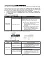
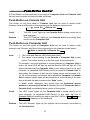
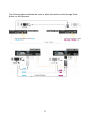
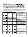
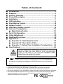
Table of Contents ■ ■ ■ ■ ■ ■ ■ ■ ■ ■ ■ ■ ■ ■ ■ Introduction………………………………………………….…….. 2 Features…………………………………………………………….. 3 Packing Checklist……………………………………….………... 4 Product Description…………………………………………….... 5 Installation…………………………………………………………. 7 LED Indicators…………………………………………………….. 9 Push-Button Control……………………………………………..10 Hotkey Control………………………………………………........12 Alternative Hotkey Control……………………………………...15 Cascade Configuration……………………………………..…...16 ■ Mask Hotkey Switch…………………………………………18 Serial Configuration…….……………………………...……......19 Video Adjustment…………………………………………………20 Additional Functions……………………………………………..22 Appendices…………………………………………………...……23 ■ Appendix A: Cable Requirements...………………….…...23 ■ Appendix B: Fiber Optics Cable...…………………….…..23 ■ Appendix C: Optical Fiber Installation Considerations....24 Specifications…………………………………………………..…26 WARNING DO NOT STARE INTO LASER BEAM, VIEW DIRECTLY INTO THE ENDS OF FIBER, OR LOOK DIRECTLY INTO THE APERTURE PORTS OF THE FIBER AT THE OTHER END. INVISIBLE LASER RADIATION CAN CAUSE EYE INJURY. Please read this manual thoroughly and follow the Installation procedures to prevent any damage to the KVM switch or any connecting device * The final specifications are based on the actual product. * Features and functions may be added or changed after the manual was written. Please visit our website to download the latest version of manual for reference. * T0 prevent damages to your installations, make sure that all devices are properly grounded. * Never disassemble the enclosure for ay purpose. This may cause personal injury and/or property damage. It contains no user-serviceable parts; please call your local deal whenever a malfunction is suspected RoHS 1 ------------------------ Introduction Fiber DVI KVM Extender consists of a Console Unit and a Computer Unit allowing users to extend the remote access/control up to 2,000 meters away from a computer or KVM Switch with only a single fiber optics cable. The DVI digital display can be optimized up to the maximum resolution of Full HD (1920 x 1080) / WUXGA (1920 x 1200) / UXGA (1600 x 1200). The dedicated Hotkey Mask feature eliminates all the hotkey control barriers caused by mixed combinations of KVM Extender(s) and KVM Switch(es) in cascading environments. The Extender can mask up itself through the hotkey mask, enabling you to bypass the cascaded Extender level and directly configure the cascaded KVM Switch by using the keyboard/mouse connected to the Extender, as if you were virtually sitting in front of the KVM Switch. The KVM Extender features everything you need for controlling computers remotely, which include dual-user access, control multiple computers by cascading KVM Switch(es), easy computer access through push button, hotkeys, and mask hotkeys, LED indicators for real-time status monitoring, serial interface for serial equipments and data communications, HDCP compliant, Blu-ray ready, audio jack (speaker + Mic) for audio display. Moreover, it is fully compatible with most of the popular monitor screen resolution such as XGA, SXGA, UXGA, WSXGA….Full HD, WUXGA system. The Fiber KVM Extender has been common used in applications that require greater distance, high speed transmission, real-time high video resolution, security, and noise immunity. It is economical and scalable design for growth-oriented enterprises, which you can easily expand the multiple computer controls by adding additional Extender(s) or cascading the Extender(s) with KVM Switch(es) whenever you need. You can secure the computers and valuable data or manage them both in remote and local sites. No software or DIP switches are required, just plug and play. It is a perfect solution for a multitude of KVM extension environment including applications in medical, military, bank, development lab, educational institution, industrial, as well as high electromagnetic interference (EMI) / radio frequency interference (RFI) environments. 2 ------------------------ Features Connect the Extender pair via SC to SC duplex Multi-mode fiber optics cable Remotely locate the keyboard, mouse and monitor up to 2000 meters away from a computer (or a KVM switch) with the maximum resolution of Full HD (1920 x 1080) / WUXGA (1920 x 1200) / UXGA (1600 x 1200). Support USB console Hotkey functions and push button for easy computer access Mask Hotkey simplify multiple computer control in cascade environment Dual-user access to share multiple computers High speed and long distance transmission by optical system Support serial interface for instant data transfer Fully compatible with DVI standard by DDWG HDCP compliant and Blu-ray ready Completely free of Electromagnetic Interference (EMI) Fully compatible with all the KVM Switch system Ideal for professional audio/ video applications Optional fiber only system without DDC function (pseudo DDC signal can be transmitted for EDID information.) Video is transmitted digitally for zero signal loss Compatible with most of the popular screen resolution to XGA, SXGA, UXGA, WSXGA ….Full HD, WUXGA system 3 ------------------------ Packing Checklist 1. 2. 3. 4. 5. 6. 7. 8. KVM Extender Console Unit KVM Extender Computer Unit Power Adapter with necessary AC Cord Or Plug-in Power Adapter User’s Manual Foot Pad Set 30-meter Multi-mode SC-SC duplex Fiber Optic Cable KVM cable Rack Mount Bracket with necessary screws x1 x1 x2 x1 x2 x1 x2 x 2 sets (option) Optional 1. Null Modem Cable (see Appendices) ★Hardware Requirements 1. Computer(s) with USB port(s) and DVI Video output port 2. USB Keyboard / Mouse for console controlling 3. Microphone, Speakers, and HDCP compliant Monitors with DVI interface for the HDCP video source (optional) 4. DVI KVM Cable(s) 5. Fiber cable 6. Serial Cable (for Serial Device Applications) KVMXF-2022C Input (Video + Audio) DVI x 2 Audio Jack Set x 2 Output (Video + Audio) DVI x 2 Audio Jack Set x 2 4 Serial Interface Mask Hotkey Switch HDCP Support DTE + DCE x2 Yes ------------------------ Product Description The following figures show typical applications of KVM Extender series. The model you have purchased may be slightly different from those described in the illustrations. KVMXF-2022C Console Unit KVMXF-2022C Computer Unit 5 F1 F2 F3 F4 F5 Serial LED Indicator RX: Data Receiving status TX: Data Transmitting status Remote LED Indicator Control Status Indication (see LED Indicators chapter) Local LED Indicator Power/Connectivity LED Indicator Control Status Indication (see LED Indicators chapter) Green: Power On Blue: Power On and connect to a powered on extender unit F6 C1 C2 C3 C4 C5 Push Button Select Control Status DTE Interface Connect to a serial device DVI Connector Connect to the monitor USB Connectors Connect to the console mouse / keyboard and mouse combo Audio Jack Connect to Speakers and MIC Mask Hotkey Switch (see figure below) OFF: Standard mode (see Hotkey Control chapter) ON: Disable the KVM Extender hotkey function P1 P2 P3 P4 O1 A1 DCE Interface Connect to a Computer DVI Connector Connect to Local PC’s Video output USB-B Connector Connect to Local PC’s USB port for Keyboard/Mouse operation Audio Jack Connect to Local PC’s Audio port SC-SC Fiber Interface Connect to the SC-SC duplex Multi-mode fiber optics cable Power Supply Apply to the appropriate power source OFF Hotkey Mask Off ON Hotkey Mask On Direct control the computer Console Unit controls its local PC Computer Unit controls its local PC Remote Control applied Remote Control enabled 6 ------------------------ Installation DO NOT STARE INTO LASER BEAM, VIEW DIRECTLY INTO THE ENDS OF FIBER, OR LOOK DIRECTLY INTO THE APERTURE PORTS OF THE SC-SC FIBER WHEN THE UNIT IS POWERED ON. INVISIBLE LASER RADIATION CAN CAUSE EYE INJURY. WARNING Before Installation z Determine where the computer and Extender Unit will be located and set up z Use SC to SC duplex Multimode fiber optics cable (50/125 or 62.5/125) for the interconnection between Computer and Console Unit. z Make sure that the Fiber cable length is long enough (not exceed 2,000 meters) for the connection between the Computer Unit and the Console Unit to prevent having to splice fiber. Try to complete the installation in one pull ● Prior to the installation, it is important to make sure that all devices you will connect to this system are properly grounded and powered off. ● The KVM Extender is HDCP compliant and required to use the HDCPcompliant display when it is connecting to the HDCP video source. ● Never disassemble the enclosure for ay purpose. This may cause personal injury and/or property damage. It contains no user-serviceable parts; please call your local deal whenever a malfunction is suspected. Connection Patterns The KVM Extender capability can be dynamically enhanced by using the KVM Switch(es) to expend the number of control on computers/servers, in which users can connect the KVM Switch to the Console Unit or Computer Unit, connect the computer to the Computer Unit and/or Console Unit, and connect the Console Unit to the Computer Unit with the appropriate fiber cable. Please follow the guidelines below for the system connection. Console Side Use a DVI cable for the connection between Unit and the monitor display. Plug a USB keyboard and a USB mouse into the Console’s USB ports. If needed, plug a set of audio jack from speaker and microphone into the Console’s speaker port and microphone port respectively 7 Computer Side Use a DVI cable for the connection between the Video port on the computer side of the Unit and the video output port of the Computer. Use a USB A-B cable to connect the Unit’s USB port (B connector, square connector) and the USB port on the computer (A connector, flat connector). If needed, use a set of audio cable to connect the speaker port and microphone port between the unit and the computer. If needed, connect a serial cable from the computer to the DCE connector on the Computer Unit, plug the serial device (DCE) into the DTE connector on the Computer Unit, and plug the serial device (DCE) into the DTE connector on the Console Unit. Use a SC to SC duplex multi-mode fiber optics cable for the SC-SC fiber port connection between the Console and Computer Unit. After all device connections are completed, connect the provided power cord into an appropriate power source and plug the opposite end into the power connector on the Unit to power up. (Refer to the following figure for the connection) KVMXF-2022C 2 Consoles → 2 Computers 8 ------------------------ LED Indicators The LEDs on the KVM Extender show the real-time status which indicates the linking, communication, and control situation between the Computer Unit and Console Unit. User can identify the present status and switch control through the LED indicators and push-button on the top panel respectively as the following descriptions: 1. Press the push-button on Console Unit to select “Local ON” or “Remote ON”. 2. Press the push-button on Computer Unit to select “Local ON”, “Remote ON” or “Auto Mode”. LEDs on Console Unit Model LED Status Remote: Off, Local: On* KVMXF-2022C (Console Unit) Remote: On, Local: Off Control Description z Console Unit controls its local PC. Console Unit is enabled to access to the Computer Unit. In this state, either of the following two statuses can be observed: z 3 LEDs (Num, Caps and Scroll Lock) on the keyboard are flashing: The Computer Unit is now taking control of the system. z 3 LEDs (Num, Caps and Scroll Lock) on the keyboard are NOT flashing: the system is waiting for Console Unit or Computer Unit to take control. ● By default, the LED status is set to Local “ON” when powering up LEDs on Computer Unit Model LED Status Control Description z Computer Unit controls its local PC (or cascaded KVM switches). In this mode, Remote: Off, Local: On the Console Unit can not take control of the Computer Unit remotely. z Console Unit can remotely taking control KVMXF-2022C Remote: On, Local: Off of the Computer Unit. (Computer Unit) Remote / Local Flashes z The system is waiting for Console Unit alternatively (Auto Mode)* or Computer Unit to take control. The control priority is on the first come, first served basis * By default, the LED status is set to Auto when powering up 9 -----------------Push-Button Control A Push-Button on the respective front panel of Computer Unit and Console Unit can be used to select the control mode as follows. Push-Button on Console Unit The button on the front panel of Console Unit can be used to switch mode between Local and Remote in the sequence as the diagram shown below: Local On → Remote On Local : Remote : The LED “Local” lights up, the Console Unit is taking control on its local computer. The LED “Remote” lights up, the Console Unit can remotely take control on the Computer Unit. Push-Button on Computer Unit The button on the front panel of Computer Unit can be used to switch mode among Local, Remote, and Auto in the sequence as the diagram shown below: Auto → Local On → Remote On Auto : 1. The Local and Remote LEDs flash alternately. 2. The system is now waiting for the Console or Computer Unit to take control. The control priority is on the first come, first served basis. For example, once the keyboard or mouse attached to Computer Unit is active, the Local LED will light up and the Remote LED will light off. This status indicates that the Computer Unit is now taking control on its local computer (or cascaded KVM Switch), and vice versa for Console Unit. In Auto mode, the duration of latch time for taking control can be preset to 5, 15, 30, or 60 seconds via hotkeys, which allows the Computer or Console Unit to resume control again via any keystroke or mouse activity if the latch time is due and the status returns to the “Auto” mode. In “Auto” mode, whenever, any activity from the keyboard, mouse buttons or mouse scroll wheel is detected, the Unit (Computer Unit or Console Unit) immediately takes control of the system. Local : The LED “Local” lights up, the Computer Unit is taking control on its local computer (or cascaded KVM Switch). In this case, the user in Console Unit can identify this status from the 3 LEDs ( Num, Caps and Scroll Lock ) flashing on the keyboard. Remote : The LED “Remote” lights up, the system can be remotely controlled by the Console Unit. 10 The following figure indicates the order in which the switch control through PushButton on the top panel. 11 -----------------Hotkey Control A hotkey command is a short key sequence to select a computer, activate computer scan, and so forth. The KVM Extender interprets keystrokes for hotkeys all the time. Throughout this user manual, the following terms are used to identify the common states during hotkey configurations: Standard Mode The state of the KVM Extender without any connection to any KVM Switch. Compatibility Mode The state of the KVM Extender with connection(s) to KVM Switch(es). The Command for Mode Switching Users can switch mode between Standard and Compatibility through inputting the hotkey command [left Ctrl + left Ctrl + Alt + E ], and then one beep is generated as the confirmation of Standard Mode; otherwise, two beeps is generated as the confirmation of Compatibility Mode. ( Alt + E : hold Alt down and press E key) Leading Code In Standard Mode, a hotkey command starts with the leading code [left Ctrl + left Ctrl ] followed by one or two more keystrokes. In Compatibility Mode, a hotkey command starts with the leading code [left Ctrl + left Ctrl + E ] followed by one or two more keystrokes. The built-in buzzer generates a high-pitched beep for correct hotkey command, otherwise, one short and one long beep are generated for a bad command, in which, the bad key command won’t be sent to the extender unit or the selected computer. Mask Hotkey Switch The hotkey commands of KVM Switches vary among models, which may cause hotkey errors, unpredictable result between the Extender Unit and mixed types of KVM Switch that connect to each other. The Hotkey Mask extremely simplifies the hotkey control in cascade architecture; through the mask ON, users can bypass the Extender Unit and directly apply the KVM Switch built-in hotkey commands to access and configure the cascaded computer(s) / KVM Switch(es). More details about this feature can be found in the following section “Mask Hotkey Switch”. Alternative Hotkey Control Press and Hold push button two seconds followed by one keystroke can be applied as the alternative to the leading code. The KVM Extender is incapable of conducting any hotkey controls when its hotkey function is masked (Hotkey Mask Switch “ON”); this alternative control is especially useful in this state. For the details of hotkey commands, please check the following sections “Hotkey Commands” and “Alternative Hotkey Control”. 12 Hotkey Commands z Prior to any hotkey command input, please enable either of the following settings: Standard Mode by inputting the hotkey command [left Ctrl + left Ctrl + Alt + E ] and then one beep should be generated as the confirmation. Compatibility Mode by inputting the hotkey command [left Ctrl + left Ctrl + Alt + E ] and then two beeps should be generated as the confirmation; or Users can switch the mode alternately by repeating this hotkey command. z Only the key Ctrl located on the lower-left corner of the keyboard is valid for hotkey commands. z The hotkey command will be automatically time-out, if there is no activity detected by the keyboard within 3 seconds after the leading code input. z When the mask hotkey switch is set to “ON”, the Extender Unit masks up itself in this state, users can sit in front of the Extender and directly apply the KVM Switch built-in hotkey commands to configure the computers that attached to the KVM Switch as if the user was virtually sitting in front of the KVM Switch. Console Unit Hotkey Commands Mask Hotkey: OFF Alternative Hotkey Hotkey Mask Hotkey: ON Alternative Hotkey Hotkey Function Description Cascading status selection One beep: enable Standard Mode Two beeps: enable Compatibility Mode, and the user at Console Unit accessing to the KVM switch that is connecting to Computer Unit. Ctrl + Ctrl +Alt+E N/A N/A N/A [Leading Code]+Esc N/A N/A N/A Escape from hotkey mode [Leading Code]+ T N/A N/A N/A [Leading Code]+F2 N/A N/A N/A Mode selection in Sequence switch console control between Local Computer and Remote Computer [Leading Code]+ 1 [Leading Code]+ 2 [Leading Code]+ Q+ L [Leading Code]+ Q+ A [Leading Code]+ Q+ H N/A N/A [BTN]+ Q + L (2 Sec.) [BTN]+ Q + A (2 Sec.) [BTN]+ Q + H (2 Sec.) N/A N/A N/A Local mode selection enable the user at the Console Unit accessing to the computer (KVM Switch) that connects to the Console Unit. N/A Remote mode selection enable the user at the Console Unit exclusive accessing to the computer ( KVM Switch )that connects to the Computer Unit. (only if the Computer Unit is in Remote or Auto mode). Disable Computer Unit user accessing to the Computer Unit during this mode. [BTN]+ Q + L (2 Sec.) [BTN]+ Q + A (2 Sec.) [BTN]+ Q + H (2 Sec.) 13 Equalization Adjustment (EQ) to level Low Set video equalizer on the monitor DVI display of the Console Unit the level of Low. Before this setting, please make sure that the Computer /Console Units are well connected by using the proper fiber optic cable and the Console Unit has been set to Remote mode. Equalization Adjustment (EQ) to level Enhanced Set video equalizer on the monitor DVI display of the Console Unit to the level of Enhanced. Before this setting, please make sure that the Computer /Console Units are well connected by using the proper fiber optic cable and the Console Unit has been set to Remote mode. (The factory default) Equalization Adjustment (EQ) to level High Set video equalizer on the monitor DVI display of the Console Unit to the level of High. Before this setting, please make sure that the Computer /Console Units are well connected by using the proper fiber optic cable and the Console Unit has been set to Remote mode. Computer Unit Hotkey Commands Mask Hotkey: OFF Alternative Hotkey Hotkey Mask Hotkey: ON Alternative Hotkey Hotkey Function Description Cascading status selection One beep: enable Standard Mode Two beeps: enable Compatibility Mode, and the users at Computer Unit accessing to the KVM switch that connects to the Computer Unit. Ctrl + Ctrl + Alt+E N/A N/A N/A [Leading Code]+Esc N/A N/A N/A Escape from hotkey mode [Leading Code]+ Ti N/A N/A N/A Mode selection in sequence Toggle switch to select Auto , Local On , or Remote On mode. [Leading Code]+ 1 N/A N/A N/A Local mode selection enable the user at Computer Unit exclusive accessing to the PC (KVM Switch) that connects to Computer Unit. Disables the Console Unit user accessing. N/A N/A Remote mode selection enable the user at Console Unit exclusive accessing to the PC (KVM Switch) that connects to Computer Unit. Disables the user at the Computer Unit accessing to the connected PC (KVM Switch). N/A N/A Auto mode selection [Leading Code]+ 2 N/A [Leading Code]+ 3 N/A [Leading Code]+F3 [BTN]+ F3 (2 Sec.) [Leading Code] + V + D [BTN]+ V + D [Leading Code] + V + M [BTN]+ V + M (2 Sec.) (2 Sec.) N/A [BTN]+ F3 (2 Sec.) N/A [BTN]+ V + D N/A [BTN]+ V + M (2 Sec.) (2 Sec.) Latch time selection Auto mode latch time setting, the extender generates 1 to 4 beeps to indicate the duration of latch time: 5, 15, 30, 60 seconds respectively. DVI display mode setting (factory default setting) Set the display on both Console and Computer Units to DVI mode that is incapable of carrying any audio signals. (Perform this setting before creating the connection between the Extender Units and/or the KVM Switch(es)) HDMI display mode setting Set the display on both Console and Computer Units to HDMI mode that is capable of carrying high-definition digital audio and video signals. (Perform this setting before creating the connection between the Extender Units and/or the KVM Switch(es)) NOTE: Standard Mode denotes the state of the KVM Extender without additional connection to any KVM switch(es). Compatibility Mode denotes the state of the KVM Extender with connection to KVM Switch(es). NOTE: [Leading Code] denotes in Standard Mode, the hotkey sequence [left Ctrl + left Ctrl ] in Compatibility Mode, the hotkey sequence [left Ctrl + left Ctrl + E ] NOTE: NOTE : [BTN] denotes Press and Hold the Push Button in the front panel for two seconds After Press and Hold the Push-Button two seconds, the hotkey state will be automatically time-out, if 1. There is no activity detected by the keyboard within 6 seconds. 2. Press the button Esc once to escape from the hotkey state. 3. Press the Push-Button once to escape from the hotkey state. 14 ------------Alternative Hotkey Control No matter whether the mask hotkey switch is set to ON or OFF, users can Press and Hold the Push-Button on the front panel for two seconds instead of the leading code [ Ctrl + Ctrl ] or [ Ctrl + Ctrl + E ] for some specific hotkey control on Extender Unit as the follows. Alternative Hotkey Control on the Computer Unit: z Latch Time Selection Select the duration of latch time: 5, 15, 30, or 60 seconds. Press & Hold Push-Button 2 Sec. + F3 z DVI Mode for Monitor Display Set the display(s) of both Console and Computer Units to DVI mode that is incapable of carrying any audio signals. (Perform this setting before creating the connection between the Extender Units and/or the KVM Switch(es)) Press & Hold Push-Button 2 Sec. + V + D z HDMI Mode for Monitor Display Set the display(s) on both Console and Computer Units to HDMI mode that is capable of carrying high-definition digital audio and video signals. (Perform this setting only on the Computer Unit before creating the connection between the Extender Units and/or the KVM Switch(es)) Press & Hold Push-Button 2 Sec. + V + M NOTE: By factory default, the display mode on Console and Computer Units is set to DVI mode. 15 -----------------Cascade Configuration The KVM Extender can be connected to the KVM Switch in compliance with the “Cascade Configuration”. In this case, there are some patterns of connection may be conducted in specific situations. However, to prevent from any conflict via hotkey commands in the cascade configuration, the hotkey commands prefixed with Compatibility mode leading code [left Ctrl + left Ctrl + E ] can be applied for directly accessing to the KVM Extender. Even better than that, instead of adding an E key for hotkey control in compatibility mode, a shortcut through Hotkey Mask totally simplifies the cascade hotkey configuration. The highly expandable cascade architecture allows easily adding additional servers /computers, please read the following important information before the Cascade Connection begins. 16 Before the Cascade Connection Before connecting the KVM Switch to the Console or Computer Unit, make sure the following statuses have been set up. 1. Determine either DVI or HDMI monitor display will be used, and then, on the Computer Unit, set monitor display mode to DVI (Press and Hold Push-Button 2 seconds + V + D ) or in HDMI (Press and Hold Push-Button 2 seconds + V + M ) according to the monitor display attached to the Console Unit. (The signal from Computer Unit is transmitted to Console Unit in single direction only, and is displayed on the monitor attached to the Console Unit. It is not necessary to make this setting on the Console Unit) 2. Enable Compatibility Mode by inputting the hotkey command [left Ctrl + left Ctrl + Alt + E ] and then two beeps should be generated as the confirmation. In the Compatibility Mode, set the control to (Local or Remote) by inputting the hotkey [left Ctrl + left Ctrl + T ] . OR Set the Mask Hotkey Switch ON or OFF according to the cascade correlation algorithm and user preference. (If the KVM Switch is directly connected to Computer Unit, switch ON the Mask Hotkey on both Units. If the KVM Switch is directly connected Console Unit, switch ON the Mask Hotkey on Console Unit.) Connect the KVM Switch to the Console or Computer Unit after above set up completed. 17 Mask Hotkey Switch (Shortcut for Cascade Hotkey Configuration) A Mask Hotkey Switch located at the rear panel of both Console Unit and Computer Unit can be slid ON/OFF to switch hotkey control between the cascaded KVM Switch / connected Computer accordingly. The factory default is set to “OFF”. Mask Hotkey Switch “ON” “OFF” In cascade architecture The Extender Unit masks up itself, as if users sit in front of the KVM Switch to directly configure the computers attached to the KVM Switch by applying the KVM Switch built-in hotkey commands. The Extender Unit is mask off, users can configure the computer attached to the KVM Switch by applying the KVM Extender built-in hotkey command prefixed with the cascade leading code [ left Ctrl + left Ctrl + E ]. In non-cascade architecture The Extender Unit hotkey function is disabled. Users can configure the computer attached to the Extender Unit by applying the KVM Extender built-in hotkey command prefixed with the noncascade leading code [ left Ctrl + left Ctrl ]. Example of Mask Hotkey set to “ON” in cascade architecture An IT administrator is sitting in front of the Console Unit, he pre-set the Console Unit to remote mode for accessing to the KVM Switch that is attached to Computer Unit, then slide “ON” the Mask Hotkey Switch on the Console Unit, after that, he can on use the Console Unit directly configuring the computer that is attached to the KVM Switch. Please also refer to the section “Hotkey Commands” for more information. LED: Remote on Mask Hotkey: on OFF Hotkey Mask Off ON Hotkey Mask Up Direct control the computer 18 -----------------Serial Configuration The KVM Extender over Fiber Optics provide serial ports on both the Console and Computer Units, which can be connected to serial terminal and serial devices for real-time data transmission and serial device configurations between the connected Console and Computer Units, such as POS, Barcode Scanners, Card Readers, Touch screens….as well. The serial passageway allows data to be sent from serial terminal attached to the serial port of the Extender Unit to the PC. Data receiving at the serial port of the Console Unit will be made available to the device attached to its serial port that can be remotely accessed from the connected Computer Unit . Serial data is passed in real-time and is not buffered for subsequent reading. The serial terminal baud rate setting must match the serial baud rate of the connected serial device, as figure shown below: *NOTE : Serial Device A → PC A (Serial Terminal) The baud rate setting of Device A and PC A should be the same. Control Status Communication Console Unit Local Device A - PC A Computer Unit Local Device B - PC B Console Unit Computer Unit Remote Remote Device A - PC B 19 LED Indicator Tx: Green Rx: Green Tx: Green Rx: Green Tx: Green Flash Red (Processing) Rx: Green Flash Red (Processing) ------------------ Video Adjustment Please make sure that all the system units and devices are connected properly before the video adjustment operation begin. To optimize the video performance, users can adjust the video equalization (sharpness) through hotkey commands or Push-Button configurations. Video Adjustment Configuration (on Computer Unit only) z DVI Mode for Monitor Display Set the display(s) of both Console and Computer Units to DVI mode that is incapable of carrying any audio signals. (Perform this setting before creating the connection between the Extender Units and/or the KVM Switch(es)) in Standard Mode: [left Ctrl + left Ctrl + V + D ] in Compatibility Mode: [left Ctrl + left Ctrl + E + V + D ] OR Press & Hold Push-Button 2 Sec. + V + D z HDMI Mode for Monitor Display Set the display(s) on both Console and Computer Units to HDMI mode that is capable of carrying high-definition digital audio and video signals. (Perform this setting only on the Computer Unit before creating the connection between the Extender Units and/or the KVM Switch(es)) in Standard Mode: [left Ctrl + left Ctrl + V + M ] in Compatibility Mode: [left Ctrl + left Ctrl + E + V + M ] OR Press & Hold Push-Button 2 Sec. + V + M NOTE: By factory default, the display mode on Console and Computer Units is set to DVI mode. NOTE: The HDMI/DVI video adjustment is applicable only if the fiber optic cable is connected and the Console Unit is set to remote mode. 20 Video Adjustment Configuration (EQ) (on Console Unit only) Users can adjust the video Equalization (sharpness) through hotkey commands or Push-Button configurations by following the instructions listed below: z EQ Adjustment through hotkey: Set the video equalization to Level Low in Standard Mode: [left Ctrl + left Ctrl + Q + L ] in Compatibility Mode: [left Ctrl + left Ctrl + E + Q + L ] OR Set the video equalization to Level Enhanced (Factory Default) in Standard Mode: [left Ctrl + left Ctrl + Q + A ] in Compatibility Mode: [left Ctrl + left Ctrl + E + Q + A ] OR Set the video equalization to Level High in Standard Mode: [left Ctrl + left Ctrl + Q + H ] in Compatibility Mode: [left Ctrl + left Ctrl + E + Q + H ] z EQ Adjustment through Push-Button: No matter whether the Mask Hotkey Switch is set to ON or OFF, through PushButton and keystroke(s), users can set the video equalization to Level Low: Press & Hold Push Button 2 Sec. + Q + L OR set the video equalization to Level Enhanced (Factory Default): Press & Hold Push Button 2 Sec. + Q + A OR set the video equalization to Level High: Press & Hold Push Button 2 Sec. + Q + H 21 -----------------Additional Functions Blu-ray Ready The KVM Extender supports high definition video such as DVD or Blu-ray and multi-channel audio, and carries the best signal from source to displays; the high bandwidth allows for the transmission of large amounts of information at a very high rate of speed. Blu-ray uses a blue-violet laser (405nm) that it has a shorter wavelength than a red laser (650nm), which makes it possible to focus the laser spot with even greater precision. This allows data to be packed more tightly and stored in less space, so it's possible to fit more data on the disc even though it's the same size as a CD/DVD. HDCP Compatibility High-Bandwidth Digital Content Protection (HDCP) protects video content as it is transmitted across DVI-D or HDMI connections. HDCP compliant devices do not allow users to make copies of protected content and frustrate non-HDCP devices to view protected content. When a new display device is added to the Extender Unit, the Unit will stop transmission of protected content until the new display device is validated by the source device. The duration of this process may last up to 15 seconds. The display will continue automatically upon successful authentication. The KVM Extender serves as a repeater between compliant HDCP source and display devices. When all display devices and the source device are HDCP compliant, high definition content will display normally. 22 -----------------Appendices Appendix A: Cable Requirements The fiber optics cable terminated with multi-mode duplex SC connectors is normally used for the interconnection between Computer Unit and Console Unit. A SC to SC duplex multi-mode fiber optics cable for standard application environment is provided in the package. Users may need to order additional fiber optics cables conforming to the application environment. The maximum cable length should not exceed 2,000 meters; otherwise, the signal degradation may occur especially for video resolution. For any additional purchase on fiber optics cables, please contact the local stores or call your dealers for help. Appendix B: Fiber Optics Cable The KVM Extender extends the remote access by using a piece of fiber optics cable with the maximum length up to 2,000 meters. Optional Cables DVI 2-to-2 Cable w/ Audio Serial Cable Audio Cable 23 Appendix C: Considerations on Duplex Multi-Mode Optical Fiber Installation DO NOT STARE INTO LASER BEAM, VIEW DIRECTLY INTO THE ENDS OF FIBER, OR LOOK DIRECTLY INTO THE APERTURE PORTS OF THE SC-SC FIBER WHEN THE UNIT IS POWERED ON. INVISIBLE LASER RADIATION CAN CAUSE EYE INJURY. WARNING 1. The OM3 multi-mode untwisted-pair fiber optics cable (50/125 and 62.5/125) terminated with SC duplex connectors is recommended to use for the interconnection between Computer Unit and Console Unit. The table below shows the specifications. Cable Diameter (Micron) 50/125uM 62.5/125uM Video Signal 1080i 1080p 1080i 1080p Max. Cable Length (meter) 2000 1000 700 350 2. Users may need to order appropriate cable lengths conforming to the application environment; however, the maximum cable length should not exceed 2,000 meters; otherwise, the signal degradation may occur especially for video resolution. 3. Check the cable length to make sure the cable being pulled is long enough for the run to prevent having to splice fiber. Try to complete the installation in one pull. Prior to any installation, assess the route carefully to determine the methods of installation and obstacles likely to be encountered. 4. Do not exceed the cable bend radius. Fiber optic cable can be broken when kinked or bent too tightly, especially during pulling. 5. Do not twist the cable. Twisting the cable can stress the fibers. Tension on the cable and pulling ropes can cause twisting. 6. Don’t look into the ends of any fiber optic cables. Exposure to invisible laser radiation may result. 24 7. Connector and Splice loss is caused by a number of factors, loss will be minimized when the number of connection and Splice is reduced, and the two fiber cores are identical and perfectly aligned, the connectors or splices are properly finished and no dirt is present. 8. Although most fiber optic cables are not conductive, any metallic hardware used in fiber optic cabling systems (such as wall-mounted termination boxes, racks, and patch panels) must be grounded. 9. Conductive cables require proper grounding and bonding for applicable conductors. 10. When initially received on the job site all fiber optic components should be carefully inspected for damage and tested for continuity or loss if damage is suspected. 11. Move small, lightweight spools of fiber optic cable by hand. Move larger reels with appropriate lifting equipment or using two or more installers skilled in the moving operation. 12. Follow the cable manufacturer's recommendations. Fiber optic cable is often custom designed for the installation and the manufacturer may have specific instructions on its installation. 25 -----------------Specifications KVMXF-2022C KB MS Monitor Audio Jack (Speaker + MIC) Serial KB MS Monitor Audio Jack (Speaker + MIC) Serial KB MS Monitor Audio Jack (Speaker + MIC) Serial KB MS Computer Interface KVMXF-2022C (Console Unit) Console Interface Computer Interface KVMXF-2022C (Computer Unit) Console Interface Front Panel LEDs HDCP Support Push Button Hotkey Max. Video Resolution Extension Distance Connection Power Consumption (Max) Weight H x W x D (mm) USB DVI 1 Set DCE USB DVI 1 Set DTE USB DVI 1 Set DCE USB Monitor DVI Audio Jack 1 Set (Speaker + MIC) Serial DTE Status Local Remote Serial Dual Color x 1 x1 x1 Rx x 1, Tx x 1 Yes Control Status Switch Yes Full HD (1920 x 1080), WUXGA (1920 x 1200) 1000M (1080P), 2000M (1080i) @50/125 or 62.5/125 duplex multi-mode fiber optics cable 9-12V DC, 7.2 W (Computer Unit) 9-12V DC, 6.3 W (Console Unit) 1030g (Per Unit) 44 x 218 x 130 Power Supply Voltage: DC 9-12V 26 Limited Warranty IN NO EVENT SHALL THE DIRECT VENDOR'S LIABILITY FOR DIRECT OR INDIRECT, SPECIAL, INCIDENTIAL OR CONSEQUENTIAL DAMAGES, LOSS OF PROFIT, LOSS OF BUSINESS, OR FINANCIAL LOSS WHICH MAY BE CAUSED BY THE USE OF THE PRODUCT EXCEEDS THE PRICE PAID FOR THE PRODUCT. The direct vendor makes no warranty or representation, expressed or implied with respect to the contents or use of this documentation, and especially disclaims its quality, performance, merchantability, or fitness for any particular purpose. The direct vendor also reserves the right to revise or update the product or documentation without obligation to notify any user of such revisions or updates. For further information, please contact your direct vendor. All the brand names and registered trademarks are the property of their respective owners. PP5-FE7700-076 Printed in Taiwan 27