1
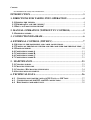
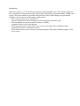
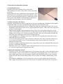
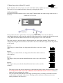
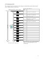
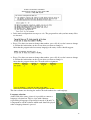
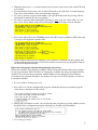
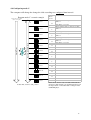
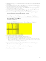
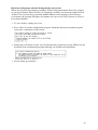
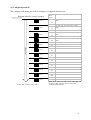
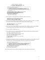
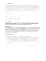
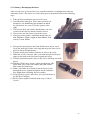
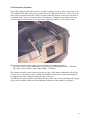
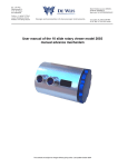
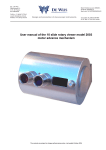
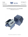
Ing. J. de Wijs.
Populierstraat 44,
4131 AR Vianen,
the Netherlands
Bank: Postbank account: 6084601,
Swiftcode: INGBNL2A
Bank code: NL24PSTB0006084601
Tel/Fax. +31 (0)347-372242
e-mail: [email protected]
Website: www.dewijs-3d.com
Tax number: NL 1899.16.084 B01
K.v.K. Reg. Nº 23071201 Utrecht
Design and production of stereoscopic instruments.
User manual for the rotary viewer model 2001
And software version 1.1
The specification subject to change without prior notices. Last update June ’02
Contents
User manual for the rotary viewer model 2001 ........................................................................................................ 1
INTRODUCTION ........................................................................................3
1. DIRECTIONS FOR TAKING INTO OPERATION ...........................4
1.1 OPENING THE VIEWER............................................................................................ 4
1.2 WHERE DO I PLACE THE VIEWER?......................................................................... 4
1.3 HOW CAN I MOUNT THE VIEWER? ......................................................................... 4
2. MANUAL OPERATION (WITHOUT PC CONTROL) .....................5
2.1 INSERTING SLIDES: ................................................................................................. 5
3. CONNECTION DIAGRAM....................................................................6
4. EXTERNAL CONTROL (WITH PC) ...................................................7
4.1 SETTING UP THE EQUIPMENT AND CABLE CONNECTIONS...................................... 7
4.2 TURNING ON THE ROTARY VIEWER AND THE COMPUTER FOR THE FIRST TIME ... 8
4.3 PROGRAM MODES ................................................................................................. 10
4.4 CONFIGURING MODE A ........................................................................................ 11
4.5 CONFIGURING MODE B......................................................................................... 14
4.6 CONFIGURING MODE C. ....................................................................................... 17
4.7 CONFIGURING MODE D. ....................................................................................... 21
5. MAINTENANCE...................................................................................23
5.1 CLEANING SLIDES................................................................................................. 23
5.2 CHANGING THE LAMP........................................................................................... 23
5.3 CLEANING / EXCHANGING THE LENSES. .............................................................. 24
5.4 SOLVING MISS-ALIGNMENT.................................................................................. 25
6. TECHNICAL DATA..............................................................................26
6.2 CHANGING MAIN POWER VOLTAGE 220 VOLT <-> 110 VOLT. ........................ 27
6.3 CONNECTIONS OF THE D25 AND D15 CONNECTORS......................................... 28
6.4 ELECTRONIC COMPONENT LIST ........................................................................ 29
Introduction
This rotary viewer is a result of 30 years experience building public stereo slide viewing equipment.
Every model had its improvements with regards to previous models meaning durability, stability and
quality. This latest model has been build using the latest CAD-CAM techniques and production
techniques. To give an idea of the changes to this model;
- The revolving drum is now motor driven.
- External control of the motor and lamp is possible through a parallel PC port.
- Internal amplifier for external speaker or phones available
- Automatic return to slide-zero function.
- The front panel and the casing of the rotary viewer can be taken away to build the whole
mechanical part into a custom made casing.
- The backside of the viewer is inclusive the mains plug flat. This allows mounting against a wall
or on a socle.
1. Directions for taking into operation
1.1 Opening the viewer.
Disconnect all cables from the viewer at the back.
Take both bolts out of the casing of the viewer at the front,
see picture
Now grab the lens tubes, pull on these lenses upwards. This
should release the mechanical construction from the casing;
two pins at the top of the front panel are coming out of two
holes in the casing. Pull the total mechanical construction
out of the casing and place it on a flat solid table.
1.2 Where do I place the viewer?
Obviously you already have chosen a spot for the viewer in your museum, exhibition or other public
environment. Here are some considerations that might help you to check the spot;
− Keep in mind the height of the viewer. Children and grown-ups both want to look in the viewer!
− Depending on the interest of the viewer, people might form a queue. This could cause congestion
for the rest of the public.
− Watch out for sunlight coming through the lenses! The lenses will act like burn glasses on the
slides. A few minutes in the sun will cause enough damage to the slide that it should be replaced.
Within 1 day, in worst case, you have to replace all slides. You can see this on the slide like tiny
little white spots showing the track of the sun during the day.
− Avoid spotlights to be shinning on the lenses. The slides are not going to be burned but it does
shorten the lifecycle of the slide.
− Cover the back opening of the viewer with all its connectors and cables. Avoid the public to get
access to this part of the viewer. Let the installation of the electrical cables be executed by
authorised personal only.
− Do always provide a grounding facility to the casing of the viewer. By default the Euro connector
provides a solid Earth connection.
− When the viewer is to be mounted inside some kind of panel, be sure you can get easy access to
the viewer for replacing the lamp bulb and slides.
1.3 How can I mount the viewer?
− The rotary viewer can be used hanging on a wall or mounted on a table. At the back of the viewer
and the bottom, 4 holes are located. It is recommended, in hanging position, to use a solid steel
plate, which can be ordered at out company, together with the housing of the viewer, to mount
against the wall. This avoids bending of the steel case when, for example, children hang on the
lenses
− For temporary exhibitions, it is best to place the viewer on a table without any fixation to the
table. Again, when children get access to the viewer, use double-sided tape to fix it to the table.
4
2. Manual operation (without PC control)
In this situation, the rotary viewer is used in stand-alone mode, without any external control devices.
This mode is also recommended when inserting or changing the slides.
2.1 Inserting slides:
Disconnect all cables from the viewer at the back. Take both bolts out of the casing of the viewer at
the front.
Now grab the lens tubes, pull on these lenses upwards. This should release the mechanical
construction from the casing; two pins at the top of the front panel are coming out of two holes in the
casing. Pull the total mechanical unit out of the casing and place it on a flat solid table.
The rotary viewer is able to work in 4 different modes, in stand-alone situation. These modes are
configurable using the small switches at the back of the viewer. The black square marks the position
of the switch.
Mode 1:
After the pre-set shut-off time, the lamp turns off and the viewer stays at this
slide.
1 2 3 4
Mode 2:
After the pre-set shut-off time, the lamp turns off and the drum revolves to
slide number 1.
Mode 3:
The lamp is always on, after the shut-off time the viewer stays at the current
slide.
1 2 3 4
1 2 3 4
Mode 4:
The lamp is always on, after the shut-off time the drum revolves to slide
number 1.
1 2 3 4
− The rotary viewer can now be turned on by connecting the power cable at the back of the viewer.
BE SURE THAT THE VOLTAGE CORRESPONDS WITH THE MAIN VOLTAGE. Look at
chapter 6.2 how to change this setting.
− You can adjust the shut-off time of the lamp by turning with a screwdriver the knob beside the
small switches at the back of the viewer. Turning counter clockwise will increase the time,
turning clockwise will decrease it.
5
Line-in cable at the CDROM is connected to
the ear-plug or rear
connector but NOT the
sound-card.
Internal CD-ROM in PC
Line-in
Light turn-off delay
Viewer control interface
SW4:
SW3:
SW2:
SW1:
Language selection box
Dutch Enlish German French
Fuse
Main power supply
The viewer is preset to a
certain Voltage, check this
before plugging it to a wall
socket
light turn-off delay active
light always on
front button passes signal to external device.
front button directly controls viewer
after light turns off, nothing happens
after light turns off, drum goes to slide Nº 1
amplifier turned off
amplifier turned on
external switch box
updownupdownupdownupdown-
3. Connection diagram
6
4. External control (with PC)
In this situation, the rotary viewer is able to operate according to a configured
program with audible explanation of the slide. An IBM compatible PC is
required to work with the accompanied software of the rotary viewer to control
the rotary viewer.
4.1 Setting up the equipment and cable connections
List of materials:
− Rotary viewer of ‘de Wijs’ model 2001 A, B or C.
− Language panel (if you need it).
− 2 Euro connector power cables.
− 1 parallel extension cable with a male D25 and female D25 plug.
− An IBM compatible x86 computer with at least 1 free parallel printer port connector and CDROM player, complete it with the usual keyboard, monitor, etc. (mouse not necessary)
− 3.5” Boot disk for the rotary viewer.
− An audio cable with 2,5 mm stereo jack to double cinch or headphones.
− 2 Loudspeakers of 4 ohms. 10 Watts maximum (optional).
Connect all cables according to the connection diagram (chapter 3). Depending on your situation you
can decide to choose for headphones or loudspeakers. The rotary viewer has an internal amplifier for
the loudspeakers. You can connect the speakers to the ¼” stereo jack.
Set the small switches at the back of the rotary viewer according to the picture
on the right when you want to use the internal amplifier.
1 2 3 4
7
4.2 Turning on the rotary viewer and the computer for the first time
Insert the bootdisk of the rotary viewer in the 3.5” disk drive of the computer. Be sure that
the drum of the rotary viewer is free to revolve! Take any obstructions or half-inserted
slides out of the drum.
Turn the computer on and insert the power cable in the rotary viewer. Be sure that the sign
of the voltage on the back is the same as your mains voltage. It is possible that during the
start-up sequence, the lamp of the rotary viewer is turned on and off as well as the drum
starts revolving and stops.
If you start-up this program for the first time, the program responds like:
Press on ‘1’ to continue in the English language. The program resumes with the following
message:
Press <Enter> to continue. The program resumes with the following message:
As soon as you press <Enter>, the program starts to detect the rotary viewer. Keep on
pressing and releasing the front panel button until the program finds the right parallel port.
Now press <Enter> to start the detection.
8
When the program fails to find the parallel port it responds with:
When it fails, press <Enter> to continue and the program repeats previous steps until it
actually finds the correct parallel port and rotary viewer.
When the program succeeds in finding the correct parallel port, it responds with:
The program is counting the amount of slides and determines the type of rotary viewer.
After that it should finish with the following message:
Press <Enter> to continue.
If you want to have more than one language accompanying your slides, you need a
language panel. Press <Y> if you want to have a language panel. The program responds
with:
You are now finished with the initial settings of the rotary viewer. The program will
respond with showing the main menu:
9
4.3 Program modes
The software enables the rotary viewer to operate in different modes. Each mode has its own
specific way of handling the CD-ROM audio tracks, timing and interaction with the spectator.
In the main menu, press option <2> and a list of modes A-D is displayed with a
description:
Decide what mode matches your requirement and chose that mode by pressing
<A, B, C or D>.
The program returns to the main menu, displaying the chosen mode on top of the screen.
Follow the appropriate instructions in 4.4 / 4.5 / 4.6 or 4.7 that belong to your chosen
mode.
10
4.4 Configuring mode A
The spectator controls the moment of slide change. Each slide will be accompanied with a
sound track from the CD-ROM. Be sure you have a list of audio-CD tracks prepared for each
slide with the selected language. To give an indication of the ‘play-out’ scenario look at the
picture below. The big downwards aiming arrow is standing for the elapsed time.
Program mode A scenario example
time for audio
CD track 1
Waiting time for front panel
button to change slide
Waiting time for front panel
button to change slide
Slide 2
10
5
audio
CD track 3
Slide 3
audio
CD track 4
Slide 4
audio
CD track 5
Slide 5
audio
CD track 6
elapsed Time
8
2
}
audio
CD track 7
audio
CD track 8
audio
CD track 9
audio
CD track 10
audio
CD track 11
audio
CD track x
At last slide; return to start position
Slide 6
Slide 7
Slide 8
Slide 9
Slide 10
Slide 11
Slide x
Kind of slide escort
Spoken text or audio fragment for
slide number 1
Slide 1
}
audio
CD track 2
Show time
slides in
seconds
12
1
10
1
8
1
7
1
11
1
10
1
9
1
12
1
10
1
9
extra viewing time+ slide change of 1 second.
Spoken text or audio fragment for
slide number 2
extra viewing time+ slide change of 1 second.
Spoken text or audio fragment for
slide number 3
slide change of 1 second.
Spoken text or audio fragment for
slide number 4
slide change of 1 second.
"
"
"
"
"
"
"
"
"
"
"
"
"
"
"
In this mode, each slide will be accompanied with its
own audio CD-Track.
11
Programming this mode is not that difficult. Press on option <3> on the main menu
screen. The program will ask you how many slides you want to insert in the drum:
Press <Y> when you want to change that number, press <N> if you don’t want to change
it. Follow the instructions on the screen when you want to change it.
After that the program asks how many languages the rotary viewer should support:
Press <Y> when you want to change that number, press <N> if you don’t want to change
it. Follow the instructions on the screen when you want to change it.
After that the program shows the slide number – CD audio track assignment:
The left column shows the slide number.
The other four columns are showing the audio-CD track numbers for each language.
Language selection:
At the back of the rotary viewer it is possible to connect a
language selection box. This is a box with 4 buttons
representing 4 languages. Especially for mode A, B and C it
is important to instruct the software which track should be
played when a language button is pressed.
With the arrow keys () on the keyboard you can move the cursor around in this
table to the audio-CD track to be edited.
Use your prepared list of audio-CD tracks to be played for a certain slide and language.
Type these track numbers in the corresponding columns.
As soon as you have typed a track number, you can check this track by pressing <P> for
playing this track and <S> for stop playing.
12
As example look at slide number 3. As soon as the viewer arrives at slide number 3 it will
play audio CD-track 3. When the spectator is pressing language button 2, the viewer
won’t change the slide but starts playing audio track 24, etc. Look at the picture below….
As soon as you have filled in the table according to your ‘play list’, Press <Esc> to exit
this screen. The following question appears:
The silent period is the time that elapses after the audio-CD track has finished with
playing for each slide. Press <Y> to change this setting. Type the new period of <15>
seconds and press <Enter>. The program will then automatically return to the main
configuration menu.
To save all these settings press <8>.
Press <Esc> to exit the configuration program. Automatically the presentation program
starts after a countdown of 10 seconds.
During the presentation session, you can interrupt the program by pressing <Enter> on the
keyboard to the configuration program allowing you to make any adjustments.
Screen during presentation……
13
4.5 Configuring mode B.
The computer controls the moment of slide change. One track will be played and the interval
time is equally split up over this track.
Program mode B scenario example
Waiting time for front panel
button to change slide
Show time
slides in
seconds
M usic, natural sounds. Sound that is not
stricly related to one specific slide.
Slide 1
12
1
12
1
12
1
One long audio CD-track
elapsed Time
Slide 4
12
1
Slide 5
Slide 6
Slide 7
Slide 8
12
1
12
1
12
1
12
1
Slide 9
12
1
Slide 10
12
1
Slide 11
Slide x
At last slide; return to start position
slide change of 1 second.
M usic, natural sounds. Sound that is not
stricly related to one specific slide.
Slide 2
Slide 3
Kind of slide escort
slide change of 1 second.
M usic, natural sounds. Sound that is not
stricly related to one specific slide.
slide change of 1 second.
M usic, natural sounds. Sound that is not
stricly related to one specific slide.
slide change of 1 second.
"
"
"
"
"
"
"
"
"
"
"
"
"
12
"
1
"
12
In this mode, there is only one audio CD-track, the
duration of the track will be divided over the
available slides.
14
In the main configuration screen press <4>. The program first asks you how many slides
are inserted:
Press <Y> when you want to change that number, press <N> if you don’t want to change
it. Follow the instructions on the screen when you want to change it.
After that the program asks how many languages the rotary viewer should support:
Press <Y> when you want to change that number, press <N> if you don’t want to change
it. Follow the instructions on the screen when you want to change it.
After that the program shows the CD audio track assignment:
The four columns are showing the audio-CD track numbers for each language.
Language selection:
At the back of the rotary viewer it is possible to connect a
language selection box. This is a box with 4 buttons
representing 4 languages. Especially for mode A, B and C it
is important to tell the software which track should be played
when a language button is pressed.
15
With the arrow keys () on the keyboard you can move the cursor to the audio-CD track
to be edited.
You should have worked out a list of audio-CD tracks to be played for a certain language.
Type these track numbers at the corresponding languages.
As soon as you have typed a track number, you can check this track by pressing <P> for
playing this track and <S> for stop playing.
As soon as you have filled in the table according to your ‘play list’, Press <Esc> to exit
this screen. All available audio CD track languages are now being tested on duration.
Insert your audio CD in the CD-ROM player of the PC and press <Enter>. When the track
is accepted, the program responds with:
When you have more than one language, press <Enter> to continue and the program will
resume with the other languages to be tested. If this is not the case, the program returns to
the main configuration menu.
Behaviour of language selection during the play-out session.
When you only have one language available, only the front panel button allows the spectator
to start a presentation. When you have 2-3 languages available, the front panel button will be
disabled. You can start the presentation with the buttons on the language panel. During a
presentation, the program will ignore any buttons to be pressed. It only responds as soon as a
presentation finishes.
To save all these settings press <8>.
Press <Esc> to exit the configuration program. Automatically the presentation program
starts after a countdown of 10 seconds.
During the presentation session, you can interrupt the program by pressing <Enter> on the
keyboard to the configuration program allowing you to make any adjustments.
Screen during presentation……
16
4.6 Configuring mode C.
The computer will change the change the slide according to a configured time interval.
Program mode C scenario example
Waiting time for front panel
button to change slide
Show time
slides in
seconds
M usic, natural sounds, spoken text for slide
number 1
Slide 1
12
1
Slide 2
8
1
Slide 3
5
1
One long audio CD-track
elapsed Time
Slide 4
13
1
Slide 5
Slide 6
Slide 7
Slide 8
11
1
12
1
9
1
8
1
Slide 9
13
1
Slide 10
14
1
Slide 11
Slide x
At last slide; return to start position
Kind of slide escort
slide change of 1 second.
M usic, natural sounds, spoken text for slide
number 2
slide change of 1 second.
M usic, natural sounds, spoken text for slide
number 3
slide change of 1 second.
M usic, natural sounds, spoken text for slide
number 4
slide change of 1 second.
"
"
"
"
"
"
"
"
"
"
"
"
"
11
"
1
"
7
In this mode, there is only one audio CD-track, the
moment of slide-change is programmed and based on
the elapsed time of the audio track coming from the
CD-ROM player.
17
Press <5> to go to the mode C settings-menu:
Press option <1> if you want to change the number of available languages.
Press option <2> if you want to change the number of inserted slides.
Press option <3> and the following screen will appear:
The four columns are showing the audio-CD track numbers for each language.
Language selection:
At the back of the rotary viewer it is possible to connect a
language selection box. This is a box with 4 buttons
representing 4 languages. Especially for mode A, B and C it
is important to instruct the software which track should be
played when a language button is pressed.
18
With the arrow keys () on the keyboard you can move the cursor to the audio-CD track
to be edited.
You should have worked out a list of audio-CD tracks to be played for a certain language.
Type these track numbers at the corresponding languages.
As soon as you have typed a track number, you can check this track by pressing <P> for
playing this track and <S> for stop playing.
As soon as you have filled in the table according to your ‘play list’, Press <Esc> to exit
this screen and the program will return to the mode C settings-menu.
Press <4> to go to the time recording procedure. First the following question appears:
Press <1,2,3 or 4> to select the language for which you want to record the slide
transitions. Then the program asks to insert your audio-CD ROM in the CD-ROM drive:
Insert the audio-CD ROM and press <Enter>. The recording screen is displayed.
Press <Enter> and the actual recording starts;
♦ the rotary viewer changes the first slide, the lamp turns on.
♦ The audio-CD is played and you hear the contents of the track.
♦ Use your prepared script on which moment the rotary viewer should change the slide.
When you hear that moment passing by, press <Enter>. That moment is now recorded
and the rotary viewer will change to the next slide.
Repeat previous steps for all other slides until you finished them all. After that press
<Esc> to return to the mode C settings menu.
You can select option 4 to record time transitions for other languages.
Press <Esc> to exit the mode C settings menu.
19
Behaviour of language selection during the play-out session.
When you only have one language available, only the front panel button allows the spectator
to start a presentation. When you have 2-3 languages available, the front panel button will be
disabled. You can start the presentation with the buttons on the language panel. During a
presentation, the program will ignore any buttons to be pressed. It only responds as soon as a
presentation finishes.
To save all these settings press <8>.
Press <Esc> to exit the configuration program. Automatically the presentation program
starts after a countdown of 10 seconds.
During the presentation session, you can interrupt the program by pressing <Enter> on the
keyboard to the configuration program allowing you to make any adjustments.
Screen during presentation……
20
4.7 Configuring mode D.
The computer will change the slide according to a configured time interval.
Program mode D scenario example
Waiting time for front panel
button to change slide
Show time
slides in
seconds
No audio, only text card on the revolving
drum
Slide 1
10
1
Slide 2
10
1
Slide 3
Slide 4
10
1
10
1
elapsed Time
Slide 5
Slide 6
Slide 7
Slide 8
10
1
10
1
10
1
10
1
Slide 9
10
1
Slide 10
10
1
Slide 11
Slide x
At last slide; return to start position
Kind of slide escort
slide change of 1 second.
No audio, only text card on the revolving
drum
slide change of 1 second.
No audio, only text card on the revolving
drum
slide change of 1 second.
No audio, only text card on the revolving
drum
slide change of 1 second.
"
"
"
"
"
"
"
"
"
"
"
"
"
10
"
1
"
10
In this mode, there is no audio escort of the slide. The
moment of slide change is based on the fixed
configured time interval.
21
Press option <6>. The program asks how many slides are inserted:
Press <Y> if you want to change the number of slides. Press <Enter> or <N> to stay with
the current number. The program resumes with the interval time setting:
Press <Y> if you want to change the interval time. Press <Enter> or <N> to stay with the
current interval time. The program returns to the main configuration screen.
To save all these settings press <8>.
Press <Esc> to exit the configuration program. Automatically the presentation program
starts after a countdown of 10 seconds.
During the presentation session, you can interrupt the program by pressing <Enter> on the
keyboard to the configuration program allowing you to make any adjustments.
Screen during presentation……
Note: The spectator is always able to change the slide faster than the interval time.
22
5.
Maintenance
In general does the rotary viewer not need any mechanical maintenance using it on a fixed
location and handled with care. The viewer is made quite solid with the aim to guarantee the
best optical alignment of the lenses as long as the life cycle of the viewer is. A hard impact at
the front, like tumbling from a table, causes inevitable miss-alignment of the drum and a bend
frame. So be careful when transporting the viewer and arrange a stable spot to place the
viewer. Besides these incidents, the viewer gets covered with a thin layer of dust, outside as
well as inside.
5.1 Cleaning slides.
Open the viewer according to the actions to be taken in chapter 1.1
You have two types of slide mounts;
- mounted in masks and encased in glass.
- mounted in frames without glass
Encased in glass:
In this case you do not have to take the slides out of the drum. Best is to turn the rotary viewer
into manual operation (chapter 2.1 mode 2). Take a soft cloth, clean the slide first at the
outside of the drum. Secondly clean it at the inside of the drum. When cleaning it push it a
little inside out of the drum to preserve fixed focus position of the slide.
Without glass:
This is a difficult situation. Slide frames without glass are very fragile. Taking them out of the
drum, cleaning them, and replace them back again often causes damage to the slide. So if you
can, take a soft brush and wipe the dust away at both sides. When the dust is too much, then
there is no other way than taking them out of the drum. Try cleaning it with the brush and
finally with a soft lens cleaning cloth. Be very careful, some clothes can even scratch the
slides, or decreases the clearness.
5.2 Changing the lamp
•
•
•
Open the viewer according to the actions to be taken in chapter 1.1
At the left side of the frame is a square hole located in the metal frame that gives access to
the lamp. By just pulling on the bulb with your fingertips would release it from its socket.
Replace the lamp with a similar model and colour temperature of at least 5000 Kº or in
more common words: Philips PL 84 or Osram PL 34, both for 9 Watts. This colour
temperature is important to let the slide give its original colour in stead of the lamp, 5000
Kº gives almost white.
When you transport the viewer, it is recommended you take the lamp bulb out of the viewer.
It happens often that the lamp drops out of its socket and breaks during transport.
23
5.3 Cleaning / Exchanging the lenses.
After several years of use the lenses are scratched and dust is coming between the two
achromatic lenses. The lenses are can be taken apart to clean them. Follow the following
steps:
1. Take the inner mechanical part out of its cover.
2. Just behind the front plate, where the two barrels are
mounted, is an aluminium plate mounted in which
the lens barrels are screwed. See the picture at the
right.
3. Unscrew the bolts just a little, which allows you now
to unscrew the two lens barrels from the viewer.
4. Unscrew the two lens barrels out of the viewer.
5. Now you need to make a small little metal plate of 1
mm. Thickness. With a length of about 60 mm. And
exactly 37 mm. Width.
6. Now put the metal plate in the back off the barrel and be sure it
fits in the small gaps of the screw ring that keeps the lenses in its
barrel as shown in right picture…
7. Turn the metal plate counter clockwise to release the screw.
8. When the screw is released, take a soft cloth and put it with your
finger in the back of the lens barrel against the lenses.
9. Turn the total barrel upside down so the lenses will drop out of the
barrel.
10. Warning!! The lenses do have a front and backside. The
front (view side) is the side with the most flat surface.
This counts for both lenses.
11. With a soft clothe and a brush cleans the lenses. Look
through the lenses against the light to check cleanliness
they might show remaining dust of scratches.
12. If you decide to replace the lenses, you can order them at
the De Wijs Company.
13. Put the lenses together and follow the steps (1-10) in
reverse.
24
5.4 Solving miss-alignment.
Especially during installing the viewer in a public viewing area, parts of the viewer have to be
de-assembled. The drum is the most sensitive part to be aligned for the lenses. The axis of the
slide drum is mounted in brackets. These brackets allow the drum to be moved to the front or
to the back of the viewer and up and down. To make the re-alignment somewhat easier you
can check some measurements to get the drum roughly in position, see the picture below.
The distance from the centre of the axis to the inner side of the front plate is:
- For rotary viewer model A&B, that is 41x101 mm. and 50x50 mm. Frames, 170,5 mm.
- For rotary viewer model C, that is 60x130mm., 172,0 mm.
The distance from the centre of the axis to the top edge of the frame is 40 mm for all models.
you have to be sure that the slide is visible in the middle of the lenses. So the total drum can
be shifted to the left or right by turning the nuts on the axis.
CAUTION: the optical switches just behind the front plate, close to the push button are fragile
and need to be handled with care when taking the drum out of the frame or replacing it.
25
6. Technical data
6.1 Sizes and dimensions
Rotary viewer 2001 model A, for 41x101 mm. Frames
− Maximum picture format: 28x33 mm.
− Lenses: double coated achromatic ø 37 mm. F= 120 mm. (total 60 mm.)
− Maximum amount of slides: 21.
− Text card size: ??
Rotary viewer 2001 model B, for 50x50 mm. Frames
− Maximum picture format for 50x50 mm. Frames: 36x36 mm.
− Lenses: double coated achromatic ø 37 mm. F= 120 mm. (total 60 mm.)
− Maximum amount of slides: 17
− Text card size: ??
Rotary viewer 2001 model C for 60x130 mm. Frames.
− Maximum picture format for 60x130 mm. Frames: 55x55 mm.
− Lenses: Single coated achromatic ø 33 mm. F= 100 mm.
− Maximum amount of slides: 14
− Text card size: 58x63 mm.
General data:
− Weight rotary viewer with front plate: 12,5 kg. Cover: 6,6 kg.
− Illumination: 9 Watt PL tube light, model cool white.
− Size of milk glass to diffuse the light: 205x86 mm.
− Power supply: 220 Volts or 110 Volts. This is a fixed setting on the Printed Circuit Board
(PCB). To change this, look at chapter 6.2
− Power consumption:…… Watt.
− The rotary viewer is fused for 1 A slow.
− On the PCB are also 2 fuses located for 5Volt dc. and 12 Volt dc both for 1 A slow.
− Amplifier: the input of the amplifier should be pre-amplified.
− Output impedance of 4 ohms for the speakers.
− Maximum audible output power is 10 Watts for each speaker.
− D25 connector providing an interface to an XT/AT parallel port of a computer.
− D15 connector providing an additional interface to an external language selection device.
− The D15 connector is also providing an external stabilised power supply of +5 and +12
Volts.
− Adjustment of the turn-off time of the lamp is possible between 5-70 seconds.
− The software that is provided with the rotary viewer is written in Pascal 7.0 and runs on
DOS. On almost every x86 machine with CD-ROM player the software will work. A
Windows version will be available in the future.
26
6.2
Changing main power voltage 220 Volt <-> 110 Volt.
Most European countries use 220 – 240 Volt. The US uses 110 Volts. The rotary viewer can
be switched between these two voltage options. To do this is not easy and it requires some
technical skill: follow the next steps.
1.
2.
3.
4.
5.
Take the total mechanical part out of it’s housing.
Disassemble the back cover of the electronic circuitry.
Disconnect all cables and leads (remember their position).
Disassemble the PCB.
Now look at picture … of the PCB. There are 2 yellow lines drawn, showing the
connections to be made when running the viewer on 110 Volts. The bleu line is the
connection to be made in 220-240 Volt configuration.
6. Re-assemble the PCB back, the cables and the back cover of the electronic part.
7. Put a sign on the back panel indicating the actual of voltage setting!!!!
ef
or
1
5Vo
lts
Fu
s
for
2V
olt
s
e
Fus
220Volts-110Volts
selection
Transformer
27
6.3
Connections of the D25 and D15 connectors.
D25 connector:
Connector Description computer side and
pin
addressing
1
Strobe
Base+2 bit 0
2
D0
Base+0 bit 0
3
D1
Base+0 bit 1
4
D2
Base+0 bit 2
5
D3
Base+0 bit 3
6
D4
Base+0 bit 4
7
D5
Base+0 bit 5
8
D6
Base+0 bit 6
9
D7
Base+0 bit 7
10
Acknowledge Base+1 bit 6
11
Busy
Base+1 bit 7
12
Paper end
Base+1 bit 5
13
Select out
Base+1 bit 4
14
Auto feed
Base+2 bit 1
15
Error
Base+1 bit 3
16
Init
Base+2 bit 2
17
Select in
Base+2 bit 3
18
Gnd
19
Gnd
20
Gnd
21
Gnd
22
Gnd
23
Gnd
24
Gnd
25
Chassis
ground
Description rotary viewer
side
Not used
Change slide, 1= moving
Lamp, 1=lamp on.
Not used
Not used
Loopthrough to D15 con.
Loopthrough to D15 con.
Loopthrough to D15 con.
Loopthrough to D15 con.
Button front panel, 1=pressed
Loopthrough to D15 con.
Light gate ‘zero’ detection.
Light gate ‘stop’ detection.
Not used
Loopthrough to D15 con.
Not used
Not used
D15 Connector: (for language selection box)
Connector Description computer side and Description rotary viewer
pin
addressing
side
1
Busy
Base+1 bit 7
Loopthrough to D25 con.
2
Ground
3
+12 Volt.
4
+5 Volt.
5
D5
Base+0 bit 5
Loopthrough to D25 con.
6
D6
Base+0 bit 6
Loopthrough to D25 con.
7
D7
Base+0 bit 7
Loopthrough to D25 con.
8
Error
Base+1 bit 3
Loopthrough to D25 con.
9
D4
Base+0 bit 4
Loopthrough to D25 con.
10
11
12
13
14
15
Direction looking from
computer side.
Output
Output
Output
Output
Output
Output
Output
Output
Output
Input
Output
Input
Input
Output
Input
Output
Output
Direction looking from
computer side.
Input
Output
Output
Output
Input
Output
28
6.4
Electronic component list
R1
R2
10K 1/4 Watt IR detect
10K 1/4 Watt IR detect
R3
R4
R5
R6
R7
R8
100K 1/4 Watt
10K 1/4 Watt
100K 1/4 Watt
10K 1/4 Watt
10K 1/4 Watt
100K 1/4 Watt
R9
R10
R11
R12
R13
R14
180 1/4 Watt
100 1/4 Watt
2K7 1/4 Watt
100K 1/4 Watt
1M 0.15 Watt 10 mm. standing Pot.
wire
R15
R16
R17
R18
R19
R20
2K7 1/4 Watt
wire
wire
100 1/4 Watt (IR LED’s)
100K 1/4 Watt
10K 1/4 Watt
R21
R23
R24
P1
P2
C1
22 1 Watt
10K 1/4 Watt
10K 1/4 Watt
10K 0.15 Watt 10mm. Hor. Pot
10K 0.15 Watt 10mm. Hor. Pot
47uF 10 Volt axial
C2
C3
C4
C5
C6
C7
100n 50 Volt polyester
220n 50 Volt polyester
100n 50 Volt polyester
220n 50 Volt polyester
2200uF 25 Volt Elco rad.
100uF 16 Volt Elco ax.
C8
C9
C10
C11
C12
C13
100n 50 Volt polyester
100uF 16 Volt Elco ax.
1000uF 16 Volt Elco rad.
100n 50 Volt polyester
1000uF 16 Volt Elco rad.
47uF 10 Volt axial
C14
C15
C16
C17
C18
D1
100uF 16 Volt Elco ax.
100n 50 Volt polyester
100n 50 Volt polyester
4,7uF 50 Volt Elco rad
4,7uF 50 Volt Elco rad
1N4001
D2
1N4001
29
D3
1N4001
D4
D5
D6
D7
T1
T2
1N4001
1N4001
1N4001
1N4148
BC547b
BC547b
T3
T4
U1
U2
U3
U4
BC547b
BC547b
4081 Quad And
Relays 2x 12V
LM555 timer IC
Relays 1x 12V
U5
U6
U7
U8
U9
U10
4071 Quad Or
LM7805 1A
4049UBE
L7812CV 1,5A
LM555 timer IC
TDA1519A/N2 amplifier
J1
J2
J3
J5
J6
D25 PCB socket 90º male
Header 8 pins
Header Socket 8 pins
Euro connector PCB mounted
Header 2 pins
Header 2 pins
J7
J8
J9
J10
Header Socket 2 pins
Shrink contacts for Headers
D15 PCB socket 90º male
Single cinch PCB socket
3-Pole socket (Head phone socket)
Single cinch PCB socket
Tr1 Transformer 2x110V 2x6V 12VA
V1 Varistor 250 Volt
SW1 Dip switch 4x 90º
DIL8 sockets
DIL14 sockets
DIL16 sockets
F3
F1
Fuse holder PCB plastic
Fuse holder internal metal clamps
Opto switches 5mm. Gap
Wiring to opto coupler and front panel
switch 8 leads 70 cm. Long
Wiring to PL tube lamp 220 Volt 60 cm.
Wiring to motor; single leads 27 cm.
PCB of de Wijs company.
30