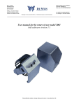
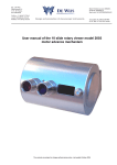
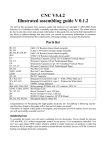
1
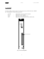
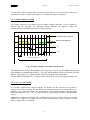
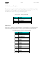
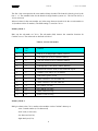
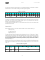
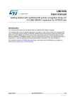
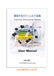
Technical
Information
Manual
Revision n. 0
29 August 1997
MOD. C 111 A
CAMAC
CONTROLLER
CAEN will repair or replace any product within the guarantee period if the Guarantor declares that
the product is defective due to workmanship or materials and has not been caused by
mishandling, negligence on behalf of the User, accident or any abnormal conditions or operations.
CAEN declines all responsibility for damages or injuries
caused by an improper use of the Modules due to
negligence on behalf of the User. It is strongly
recommended to read thoroughly the CAEN User's
Manual before any kind of operation.
CAEN reserves the right to change partially or entirely the contents of this Manual at any time and without giving
any notice
29/08/97
C111A User's Manual
TABLE OF CONTENTS
1. CAMAC CRATE CONTROLLER C111A..........................................................................1
1.1. GENERAL DESCRIPTION..........................................................................................................1
1.2. FRONT PANEL........................................................................................................................2
1.3. COMPUTER INTERFACE CONNECTION ....................................................................................3
2. CAMAC..................................................................................................................................5
2.1. INTRODUCTION TO CAMAC..................................................................................................5
2.2. CAMAC DATAWAY TIMING ................................................................................................6
2.3. LOOK - AT - ME (LAM) ........................................................................................................6
2.4. C111A CAMAC FUNCTIONS................................................................................................7
3. C111A OPERATION DESCRIPTION ................................................................................8
4. INSTALLATION .................................................................................................................12
4.1. C111A - INSTALLATION .....................................................................................................12
4.2. INTERFACE - INSTALLATION ................................................................................................12
4.3. INITIALISATION ...................................................................................................................12
5. A P P E N D I X....................................................................................................................13
i
29/08/97
C111A User's Manual
1. CAMAC Crate Controller C111A
1.1. General Description
The C111A is a standard CAMAC crate controller with 16-bit interface for computer link which
can be used in single or multi-crate CAMAC systems. Up to 15 crates equipped with the C111A
can be fully controlled from one interface. The following interfaces are available for the C111A:
• A151A for IBM-PC/AT
• A151A-TURBO for IBM-PC/AT
In a multi-crate system the geographical address of each crate is fixed by a hexadecimal front
panel swith of the C111A. All controllers C111A and the interface in one chain are connected in
parallel via a 50-wire flat or twisted pair cable (max. 30 metres / 200 metres cable length). For
proper operation the last station on each side of the chain has to be terminated by resistors.
The C111A and the available interfaces are designed for a high speed data transfer. The maximum
data rates ( depending on computer system ) are:
• CNAF-Mode:
- PC-CAMAC *:
up to 200kHz
• Block-Mode:
- PC-CAMAC*:
up to 500kHz
(* with A151A-Turbo)
The C111A consists of two boards, i.e. the controlling board (slot 25) and data transfer board (slot
24), mounted in a double width CAMAC mechanic which has to be placed in the last two slots of
the CAMAC crate (right side).
The addressing and programming of the controller is performed by cycles of I/O operations on the
interface. The A151A as well as the crate controller are prepared for interrupt based LAM
servicing. LAM lines may be enabled / disabled by jumper setting / removing on the controller
board (LAM mask).
The C111A accepts data and commands from the computer, executes the CAMAC Commands
(NAF-codes, Z, C, I) and transfers data back to the computer. For high speed data transfer block
mode operations with automatic CAMAC NAF-code repeat are possible.
In multi-crate systems broadcast calls to all controllers are simultaneously possible whereby each
single controller can be switched on / off for broadcast operations.
For all interfaces software driver / libraries are enclosed. In case of the IBM-PC/AT interfaces
there exists a wide range of software support including a ready-to-run multi-parameter data
acquisition program (WI-E-NE-R MULTI 1.1). MULTI 1.1 is a powerful program for multiparameter CAMAC based experiments( up to 23 modules / 512 parameters). It includes hardware
set-up, experiment control, fast data collection, file access and management, as well as monitoring
operations, data import and export and graphic display. Supporting a wide range of usual CAMAC
modules it allows to extend any existing CAMAC set-up to a new dimension in multi-parameter
experiments without any further development of special electronical instruments, computer
interfaces and software.
1
29/08/97
C111A User's Manual
1.2. Front Panel
Four status LED's are placed on the C111A front panel to show ACCESS, BUS ON, INHIBIT
and LAM REQUEST with the following functions,
ACCESS
Bus on
Inhibit
LAM
-
lights if there is any access from the interface
lights if the C111A is enabled
lights if the CAMAC Inhibit line is set
lights if there is a LAM request from any enabled station
CAMAC CONTROLLER
Mod. C111A
ACCESS
BUS ON
INHIBIT
LAM
ADR
INTERFACE CONNECTOR
Fig. 1, C111A front panel
2
29/08/97
C111A User's Manual
Below the status LED's a hexadecimal switch is located by which the geographical crate address
of the C111A is fixed. The allowed crate number values are in the range between 0 and 14
(hexadecimal 0-9, A, B, C, D, E)
The 50-pin connector on the front panel is mounted for parallel link to the interface (flat or twisted
pair cable). Please note that both interface and last C111A in a chain have to be terminated by
equal resistors (see next chapter)
1.3. Computer Interface Connection
For any operation the C111A has to be linked to an external interface which is driven by a microprocessor or computer. The communication between the C111A and the interface is performed
according to the CP - "Communication bus Protocol" (RS422). The CP bus consists of 16 bidirectional data lines and 7 control lines used for geographical addressing of the installed C111A as
well as for control and data transfer strobes. All signals are transferred as bipolar TTL signals.
Both the C111A and the used interface have to be terminated to enable correct function during the
high speed data transfer.
The crate controller termination is performed with resistor networks (RN2, RN4, RN5). Two types
of cable termination are provided:
Table 1 Termination resistor types (* factory prepared)
type
resistor
cable length
short distance
DIL 220 Ohm
<30m
long distance*
2 x SIL 8+1 x 100 Ohm *
>30m
Both ends of the link, i.e. C111A and interface have to be terminated with equal resistors. Note,
that in case of multi-crate systems only the last C111A in the chain has to be terminated.
Maximum tested distances between crate controller and interface are 30 metres in case of 50 pinflat cable or up to 200 metres using twisted pair cable.
Up to now 2 different interfaces are available for the C111A,
- A151A: 8/16-bit IBM-XT/AT interface card,
- A151A-Turbo: high-speed 16-bit IBM-AT interface card.
All interfaces allow multi-crate operations, i.e. up to 15 crates can be controlled by one interface.
Further it is possible to combine as many interfaces in one computer system as there are free slots
for the interface. Thus enhanced CAMAC systems can be created all controlled by one computer
system.
Further the LAM request to the C111A can be transmitted via the CP-bus to the connected
interface to allow an interrupt based LAM-servicing.
The pin assignment of the 50-pin CP-bus interface connector is given in the following table.
3
29/08/97
C111A User's Manual
Table 2, CP-bus Interface connector pin assignment
Pin
Line
Pin
Line
01
D0*
26
D12
02
D0
27
D13*
03
D1*
28
D13
04
D1
29
D14*
05
D2*
30
D14
06
D2
31
D15*
07
D3*
32
D15
08
D3
33
GND
09
D4*
34
LAM
10
D4
35
STATUS*
11
D5*
36
AKN
12
D5
37
BusN1*
13
D6*
38
BusN1
14
D6
39
BusN2*
15
D7*
40
BusN2
16
D7
41
BusN4*
17
D8*
42
BusN4
18
D8
43
BusN8*
19
D9*
44
BusN8
20
D9
45
BusMODE*
21
D10*
46
BusMODE
22
D10
47
BusWRITE*
23
D11*
48
BusWRITE
24
D11
49
BusS*
25
D12*
50
BusS
4
29/08/97
C111A User's Manual
2. CAMAC
2.1. Introduction to CAMAC
CAMAC is a standard for Computer Aided Measurement And Control. It bases on a parallel wired
bus in the back of the CAMAC crate (CAMAC dataway) with 86 lines containing
- 24 read lines (R0-23)
- 24 write lines (W0-23)
- 17 control lines (F0-F16, A0-A8, Q, X, I, C, Z, B, P1, P2)
- 2 strobe lines (S1, S2)
- 14 lines for voltage distribution (+/-6V, +/-12V, +/-24V, 115V, GND, 200V)
The CAMAC crate is prepared for 25 stations each equipped with a 2x43 pin edge card connector
on the dataway. The first 24 slots are directly connected with all parallel wired lines on the dataway
in the back of the crate.
For geographical addressing and request control each station has its own 2 lines (N, LAM) going to
the rightmost station of the crate (controller station slot 25). There the individual address lines N
are brought together as 24 station number lines (N1-N24) and the request lines as 24 LAM lines
(Look At Me, L1-L24). Via these special lines the access and request control to the CAMAC
modules is organised.
For proper operation the double width CAMAC crate controller has to be placed into the two last
right slots of the CAMAC crate to have the access to the data lines (R0-R23, W0-W23) and to the
geographical mapping of station number N and LAM request.
Each access to a module in the CAMAC crate is done via the dataway by calls of station number
N, function number F and sub-address A (NAF-code) or by calling the common CAMAC-lines C
(clear), Z (initialise) and I (inhibit).
- The station number N ranging between 1 and 23 (24-25 C111A) corresponds to
the position of the module in the crate (see numbering on crate).
- The function number F (0-31) defines the type of operation, i.e. the use of read
and/or write lines,
Table 3, CAMAC function scheme
F-code
Function
Readlines
Writelines
0-7
Read data or register
x
-
8-15
check / delete data or register
-
-
16-23
write data or register
-
x
24-31
enable / disable LAM, reserved
functions
-
-
- The sub-address A (0-15) defines special registers or inputs / channels in the
called module.
5
29/08/97
C111A User's Manual
For each used CAMAC module in the system one has to know the several NAF-codes and related
operations to be able to control and program it ( see module description or manual ).
2.2. CAMAC Dataway Timing
All CAMAC operations are performed via the CAMAC dataway whereby a series of signals is
involved into the operation. The following diagram illustrates the dataway timing and
synchronization for an addressed (with N,F,A,Data) operation.
Command & Busy (N,A,F,B)
Data & Status (R/W,Q,X)
S1
S2
100ns
Dataway Operation
Fig. 2, Dataway timing for an addressed operation
The minimum cycle time for this operation is 1µs (typically 1.2 µs). In case of reading data the status
of the read-lines is normally taken with S1. For some special modules it may be necessary to do this
with S2. Tthe jumper JA1 „Strobe Selection“ has to be changed to the left position.
The non-adressed operation (Z, C, I) differs to the scheme shown above by using only strobe S2.
2.3. Look - At - Me (LAM)
If a CAMAC module needs controller support for instance for data read out it can generate a
LAM (Look At Me). Normally for each station the LAM generation can be enabled (F=26) or
disabled (F=24) within the module. The LAM request can be detected wether at the generating
module by calling (F=8, Q=1 + X=1 if LAM pending) or by checking the controller / interface status
register.
Additionally a hardware LAM-mask can be defined on the C111A board by setting or removing
jumpers (2x23 jumper array LAM). For each station which should be able to generate a LAM
request a jumper has to be installed.
6
29/08/97
C111A User's Manual
2.4. C111A CAMAC Functions
Inserted into the CAMAC crate on the rightmost position (slot24/25) as described above the
C111A can perform the following operations:
- NAF-codes (station, sub-address, function) for module control, read / write data
- Q, X response
- setting of Z (initialise), C (Clear) or I (Inhibit)
- getting of LAM-request.
Additional functions are
- block mode with automatical NAF- code repeat,
- broadcast calls,
- bus on / off for broadcast calls,
- interrupt generation in the interface (IRQ) on LAM request,
- enable / disable IRQ - LAM servicing.
All operations and functions are described within the following chapter and in detail combined with
programming examples within the interface manuals.
7
29/08/97
C111A User's Manual
3. C111A Operation Description
The C111A access is performed via the interface by calling several modes which are for selection
of read / write operation or special controller functions. These modes are primary modes (PM)
defining the type of operation and sub-modes (SM) for the controller functions.
The functions of the primary modes are given in the following table
Table 4, C111A - Primary modes PM
PM
Function
0
set crate / branch
1
set sub-mode
2
write data (+ CAMAC cycle)
3
read data
Primary Mode 0
PM0 is used for setting of crate and branch number. The following data word GAW (Geographical
Address Word) defines the crate number according to the bit assignment given in the next table.
Table 5, Bit assignment of GAW for Primary mode 0
Bit
Reference
0
crate number 2^0
1
crate number 2^1
2
crate number 2^2
3
crate number 2^3
4
branch 1
5
branch 2
6
branch 3
7
branch 4
8
branch 5
9
branch 6
10
branch 7
11
branch 8
12
branch 9
13
branch 10
8
29/08/97
C111A User's Manual
The first 3 bits correspond to the crate number binary decoded. The branch is directly given by the
bits 4 .. 13. The standard value for the branch in single branch systems is 1. The last two bits (14,
15) are not used)
Allowed values for the crate number are in the range between 0 and 14 for the several stations or
15 (broadcast call to all stations). The PM0 setting is stored at C111A.
Primary Mode 1
PM1 sets the sub-mode at C111A. The sub-mode (SM) chooses the controller function for
CAMAC access. The sub-mode are defined as follows:
Table 6, C111A Sub-modes
SM
hexNr.
Function
0
0
write N, F, A and prompt CAMAC cycle bit
1
1
write high byte (8 bit) to CAMAC dataway
2
2
write low word (16 bit) to CAMAC dataway
3
3
read low word (16 bit) from CAMAC dataway
4
4
read high byte (8 bit) from CAMAC dataway
5
5
block mode read low word (16 bit) with NAF-repeat
6
6
CAMAC cycle with C or Z if enabled
7
7
read status register (SCB)
8
8
enable CAMAC-C for next SM6 call
9
9
enable CAMAC-Z for next SM6 call
10
A
set CAMAC-I to true
11
B
set CAMAC-I to false
12
C
enable LAM servicing
13
D
disable LAM servicing
Primary Mode 2
PM2 gives data to the C111A and/or to the modules via the CAMAC dataway as:
- crate / branch number (16 bit data word)
- NAF-code (16 bit word)
- low data word (16 bit)
- high data byte (8 bit).
9
29/08/97
C111A User's Manual
The NAF-code includes the station number N of an addressed module, the sub-address A and the
function number F. It is decoded according to the following bit assignment:
Table 7, NAF code
0
1
2
3
4
5
6
7
8
9
10
11
12
13
14
15
N1
N2
N4
N8
N16
F1
F2
F4
F8
F16
A1
A2
A4
A8
--
S
--
S
station N
function F
sub-address A
The last bit S corresponds to an immediate CAMAC cycle on a NAF-load. If this bit is 0 the NAF
load in the C111A will not cause a prompt CAMAC cycle. S=0 is necessary write data to the
dataway. For read-operations one has to set S=1.
The NAF-code is stored within the C111A. This feature allows a block read or write function with
automatically NAF repeat.
Primary Mode 3
PM3 reads data from the C111A and/or from the modules via the CAMAC dataway as:
- status byte (8-bit)
- low data word (16 bit)
- high data byte (8 bit).
The status and control byte SCB comprises the information on bus on / off, the status of CAMAC
inhibit line and on the controller LAM setting (additional enable / disable LAM request to interface,
note LAM jumper setting within C111A to enable / disable for selected modules). A pending LAM
can be read from the interface (A151A) status register only in case of correct jumper setting for
the LAM giving station and if the LAM servicing is enabled by calling sub-mode 12. The latter is
indicated by SCB bit1=1.
Only the first 3 SCB bits are used. Opposite to the first two bits for Inhibit and LAM setting status
which only have read character bit 2 can be used for read and write (bus on / off ). The crate is on
if bit2 = 0.
Table 8, SCB bit assignment
0
1
2
3
4
read
read
read /
write
read
Inhibit
LAMIRQ
Bus
on/off
not used
10
5
6
7
29/08/97
C111A User's Manual
The detailed description as well as the direct code for the most popular programming languages are
given within the interface manuals.
In case of the high speed interface A151A-TURBO the sequence of mode callings is reduced by
using higher integrated PLD´s to reach shortest access and data transfer times.
11
29/08/97
C111A User's Manual
4. Installation
4.1. C111A - Installation
Switch OFF the CAMAC crate and insert the C111A into the rightmost slots of the crate (24/25).
Be sure that the CAMAC crate Power is off if inserting or removing any CAMAC module or
the C111A
controller !!!
If a change of the hardware LAM-mask is required one has to do this before installing the C111A
in the CAMAC crate. Open the left side of the C111A remove the side panel and set / remove the
LAM jumpers on the C111A board. The LAM line is enabled / disabled if the corresponding jumper
is inserted / removed. By standard all LAM lines are enabled.
4.2. Interface - Installation
Prepare and insert the interface into the computer system. In case of A151A check the I/O
address and IRQ-number for validance and insert the board into a free IBM-PC slot of full size
(16-bit slot for 16-bit operations). If only a 8-bit slot or XT-computer is available change the jumper
setting for 8/16 bit access (jumper 1-17). The jumper 18 has to be installed for operation with
C111A.
By the help of switch 1 the basic I/O address is fixed. The standard value for I/O base address is
hex380. Note that installed devices or PC-cards (mouse, network cards, printer, ...) often use this
I/O range, too. In this case one has to look for another free range. If the C111A can not be
accessed change the used I/O address on the A151A card and in the used CAMAC software.
4.3. Initialisation
For correct operation the C111A-interface system has to be initialised first by setting the
geographical address of the called controller. Further the initial conditions for inhibit line (I - set off)
and IRQ on LAM should be defined (see next chapters). At the end of initialisation a CAMAC
initialise (Z) should be performed (see next chapter).
12
29/08/97
5. A P P E N D I X
A. List of components
B. Electrical drawings and component allocation plots
13
C111A User's Manual
29/08/97
Component list CAMAC-Crate-Controller C111A
Type
47µF /16V
82pF
------2.2pF
68p
15pF
10µF /
100nF
1N4007
1N4148
26LS32
74LS173
74LS138
74LS02
26LS31
74ALS573
74 154
74LS423
74 38
74LS74
74LS30
74LS563
74LS32
GAL20V8A
74LS04
74LS08
74LS85
74LS123
1K
Number
10
4
1
2
3
1
2
44
2
1
7
1
1
1
4
1
2
5
3
3
1
8
1
1
2
1
2
1
15
4.7K
8.2K
47K
470
220
390
10K
4+1 SIL 1K
8+1 SIL 100
4+1 SIL 470
8+1 SIL 470
7
1
1
3
3
1
3
2
6
2
3
Part-Nr.
C 1,2,3,4,5,6,7,21,22,23
C 10,11,12,13
C 14
C 15,16
C 17,18,20
C 19
C 8,9
CX 1-44
D 1,2
D3
IC 1,2,14,16,18,20
IC 10
IC 11
IC 13
IC 15,17,19,21
IC 22
IC 23,24
IC 25,29,30,31,32
IC 3,26,27
C 33,35,36
IC 34
IC 37,38,39,40,41,42,43,44
IC 4, 12
IC 45
IC 5,28
IC 6
IC 7,8
IC 9
R 1,6,10,11,16,23,24,25,
26,27,28,30,31,32,33
R 12,13,18,19,20,21,22
R 17
R2
R 14,15,29
R 3,5,9
R 34
R 4,7,8
RN 1,3
RN 2,4,5
RN 6,7
RN 8,9,10
14
C111A User's Manual
29/08/97
Type
LED-3mm red
LED-3mm yellow
LED-3mm green
socket DIL14
socket DIL16
socket DIL18
socket DIL20
socket DIL8
socket DIL24
pin array 24x2
jumper
Hex-switch
flat cable 34x
cable connector
34x
card connector
34x
connector 34x
connector 50x
Number
1
1
2
12
22
3
9
1
2
1
24
1
1
1
Part-Nr.
LED 4
LED 1
LED 2,3
IC-socket
IC-socket
RN-socket
IC-socket
for GAL-socket
IC-socket
LAMI
for LAM-jumper
SW1
100mm
1
board 25
1
1
board 24
to interface
15
C111A User's Manual