1
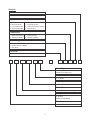
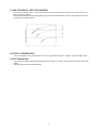
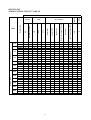
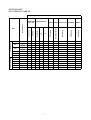
Models:
AWM07G/GR
07G/GR
A5WM
AWM09G/GR
09G/GR
A5WM
AWM10G/GR
10G/GR
A5WM
AWM15G/GR
15G/GR
A5WM
A5WM 20G/GR
A5WM 07G/GR
A5WM 25G/GR
A5WM 10G/GR
A5WM 301/1R
A5WM 15G/GR
Wall Mounted Split Systems
REGISTERED
AWM - G - 2005
ISO 9002
1. NOMENCLATURE
Indoor
Others
A : First issue
Grille Type
B : Grille B
Air Treatment Devices & Control
I : Negative Ion with wireless controller
N : NTP with wireless controller
X : Oxygen unit
Market Region
C : Export with CE mark
U : UTL Spec.
Electrical
A : 220 - 240V/1Ph/50Hz
A
WM
10
G
R
-
A
C
I
Model Type
R : Heatpump
Omitted if Cooling
Series
G : G series
Capacity
10 : 9,500 Btu/h
Model Name
WM : Wall Mounted
Refrigerant
5 : R410A
Omitted if R22
Brand
A : ACSON
1
B
A
Outdoor
Others
A : First issue
Specification Variation
O : Standard Unit
B : With Contactor
G : Low Ambient Kit
H : High Ambient Kit
I : Gold Fins
L : Long Piping Unit
S : With H/L Pressure Switch
X : Oxygen Unit
Compressor
P : Matsushita Rotary T : Toshiba Rotary
M : Mitsubishi Rotary S : Samsung Rotary
Market Region
C : Export with CE marking
E : Export without marking
U : ETL Spec.
Electrical
A : 220 - 240V/1Ph/50Hz
A
5
LC
10
C
R
-
A
C
P
O
Model Type
R : Heatpump
Omitted if Cooling Only
Series
C : C series
Capacity
10 : 9,500 Btu/h
Model Name
LC : Single Split Condensing Unit
Refrigerant
5 : R410A
Omitted if R22 Model
Brand
A : ACSON
2
A
Outdoor
Product Specification Variation
Type of Connection
F : For Flare
Electrical
A : 220 - 240V/1Ph/50Hz
F : 380 - 415V/3Ph/50Hz
A
4
LC
30
C
R
-
A
F
F
Model Type
R : Heatpump
Omitted if Cooling
Series
B : B series
C : C series
Capacity
30 : 30,000 Btu/h
Model Name
LC : Single Split Condensing
Unit
Refrigerant
4 : R410A
Omitted if R22
Brand
A : ACSON
3
A
2. FEATURES
x EASY INSTALLATION
-
The wall mounted fan coil unit is easily installed because of its compact size, slimness and light weight.
Slim and short outdoor unit can be easily installed even in a narrow balcony and passageway and yet
have a stable profile.
x SPACE SAVING
-
No space is required on either floor or ceiling. This newly developed super slim design for wall mounting
maximizes floor space usage and enhances ceiling appearance where ceilings are low.
x QUIET OPERATION
-
Cooling comfort is improved by whisper-quiet operation which is achieved by a tangential fan.
x EXCELLENT AIR DISTRIBUTION
-
Air discharge direction can be adjusted in four directions, manually or automatically by using LCD
remote control.
The new double louver design with automatic air swing function fully optimizes the room comfort by
distributing the air evenly to the room.
The unique skew fan design with larger diameter creates better air flow to the operating environment.
x FACILITATED MAINTENANCE ENSURED
-
The new design of air discharge housing whereby the fan blower can be easily accessed by just loosing
two screws on the unit to provides a flexible, faster and easier way to clean up the fan blower and
ionizer.
Maintenance is easy for electrical components, piping and wiring as these are all easily accessible by
merely removing front plastic panel.
x WIRELESS REMOTE CONTROL
-
The compact LCD transmitter is able to operate the air conditioner unit within the distance of 9 meters.
Fan motor speed can be set at low/medium/high or automatic.
Sleep mode auto control will gradually increase or decrease the setting temperature to provide a
comfortable surrounding for sleeping.
Air flow direction can be controlled automatically.
Room temperature is controlled by electronic thermostat.
The real time timer allows the air conditioner to be switched On and Off automatically based on user
settings.
Turbo mode function is available to enables the required set temperature to be achieved in a short time.
Ionizer or non-thermal plasma is available to create better air quality.
Personalized Setting allows user to preset and store 2 groups of personal settings (including timer
setting) in the handset.
Auto random restart is a function whereby when there is power failure occurred during operation, the
unit will automatically restart as the last setting condition once the power is resumed.
x MOISTURE REMOVAL
-
Dry mode with super low indoor fan speed can achieve more affective moisture removal.
If the room temperature is lower than the set temperature (Cooling mode only), the compressor will cut
out and force on after 9 minutes to remove moisture effectively.
4
x HIGH EFFICIENCY HEAT EXCHANGER
- The compact design of the 3-fold structure heat exchanger provides a large surface are for better and
efficient heat exchange.
- The unique Hydrophilic slit fin has greatly improved the air flow and the contact surfaces with the air thus
to boost the cooling capacity.
x ROTARY COMPRESSOR
-
The ever popular rotary compressor is more energy efficient and has a higher output to weight ratio.
x SELF DIAGNOSIS
-
-
This function is able to detect and to diagnose any faults occurring in the system by blinking of the LED
lights.
Simplify and ease for troubleshooting.
5
INDOOR UNIT
A5WM-G SERIES PRODUCT LINE UP
Cooling Model
09G
10G
15G
20G
25G
311
07GR
Heatpump Model
09GR
10GR
15GR
20GR
25GR
301R
X
X
X
ACIBC
X
X
ACNBC
X
X
ACXBC
X
X
X
X
X
X
X
ACIBC
X
X
X
X
ACXBC
X
X
X
X
ACIBC
X
X
X
X
ACNBC
X
X
ACIBC
X
X
ACNBC
X
X
AFCA
X
X
ACNBC
X
X
ACIBC
X
X
ACNBC
X
X
ACIBC
X
X
ACNBC
X
X
ACIBC
X
X
ACNBC
X
X
ACIBC
X
X
ACNBC
X
X
ACIBC
X
X
ACNBC
X
AFCA
X
X
X
X
X
X
Grille
B
X
X
X
X
X
X
X
X
X
X
X
X
X
X
X
X
X
X
X
X
X
X
X
X
X
X
X
X
X
X
X
X
X
X
X
X
X
X
X
X
X
X
X
X
X
X
X
X
X
X
X
6
X
X
X
X
X
X
X
X
X
X
X
X
X
X
X
X
X
X
X
ACNBC
ACIBC
X
X
Marking
X
X
Non-Thermal Plasma (NTP)
X
X
O2 Theraphy
ACNBC
Nano Technology Air Filteration
X
Saranet Filter
X
X
Ionizer Filter
X
ACIBC
U1.5
ACNBC
D2.0
X
L2.0
X
G12 (W/O Turbo mode)
ACIBC
Air Purification
Negative Ion
07G
G12
A5WM
PCB
Nomenclature
Handset
CE
CLASSIFICATIONS
X
X
X
X
X
X
X
X
X
X
X
X
X
X
X
X
X
X
X
X
X
X
X
X
X
OUTDOOR UNIT
A5LC PRODUCT LINE UP
CLASSIFICATIONS
Heat Pump Model
Marking
X
X
X
X
X
X
X
LP
X
X
HP
X
X
Contactor
X
Gold Fin
ACPOE
ACPOB
ACPXB
X
ACPOA
X
ACPXA
X
20C
ACPOC
X
X
X
25C
ACPOC
X
X
X
15C
X
X
Others
Drain Elbow
Back Panel Grille
O2 Theraphy
Special Grille Compressor
CE Marking
10C
Safety Devices
Mat. Rotary
Cooling Model
07C
Cap. Tube
A5LC
Nomenclature
Refrigerant
Ctrl + Fin
28C
ACPOA
X
X
X
07CR
ACPOE
X
X
X
X
10CR
ACPOB
X
X
X
X
15CR
ACPOA
X
X
X
X
20CR
ACPOC
X
X
X
X
25CR
ACPOC
X
X
X
X
28CR
ACPOA
X
X
X
X
7
11. CONTROLLER
G12 REMOTE CONTROLLER
Personalised Setting
Temperature Setting
x
To set the desired room
temperature, press the button to
increase or decrease the set
temperature.
x
The temperature setting range is
from 16qC to 30qC
x
Press both buttons simultaneously
to toggle the temperature setting
between qC and qF
x
Press and hold the button for 3s to
initiate personalized setting.
x
Set the individual setting e.g.
MODE, SET TEMP or FAN SPEED
and leave for 4s to save
x
2 groups of settings are allowed to
stored in the handset
OFF Timer Setting
On/Off Button
x
Press Once to start the air
conditioner
x
Press the SET button will activate
the off timer function.
x
Press again to stop the unit
x
Set the desired off time by
pressing the SET button
continuously.
x
Press the CLR button to cancel the
off timer setting
ON Timer Setting
x
Press the SET button will activate
the on timer function.
x
Set the desired on time by pressing
the SET button continuously.
x
Press the CLR button to cancel the
off timer setting
Clock Time Setting
x
Fan Speed Selection
x
Sleep Mode
Press the button until the desired
fan speed is achieved.
Turbo Mode
x
Press the TURBO button to
achieve the required set
temperature in a short time.
x
Press the button to activate sleep
mode. This function is available
under COOL, HEAT & AUTO
mode.
x
When it is activated in COOL
mode, the set temperature will be
increased 0.5qC after 30mins, 1qC
after 1 hour and 2qC after 2 hours.
x
When it is activated in HEAT
mode, the set temperature will be
decreased 1qC after 30mins, 2qC
after 1 hour and 3qC after 2 hours.
Automatic Air Awing
x
Press the SWING button to activate
the automatic air swing function.
x
To distribute the air to a specific
direction, press the SWING button
and wait until the louver move to
the desired direction and press the
button once again.
Operating Mode
x
Press the MODE button to select
the type of operating mode.
x
For Cooling only unit, the available
modes are: COOL, DRY & FAN.
x
For Heatpump unit, the available
modes are: AUTO, COOL, DRY,
FAN & HEAT.
Ionizer
x
Press button + or - to increase or
decrease the clock time.
Press the button to activate the
negative Ion function, which will
refresh the indoor air effectively.
8
INDICATOR LIGHTS
AWM / A5WM - G SERIES
IR signal receiver
When there is infrared remote control operating
signal, the signal receiver on indoor unit will made a
(beep) for signal acceptance confirmation.
Cooling unit / Heatpump unit
LED Indicator Lights for Cooling Unit / Heatpump
The table below shows the LED indicator light for air
Unit
conditioner unit under normal operation and fault
condition. The LED indicator lights are located at the
middle of the air conditioner unit.
The heat pump units is equipped with an “auto” mode,
whereby the unit will provide reasonable room
temperature by switching the unit automatically to
either “cool” mode or “heat” mode, according to the
temperature setting set by the user.
LED Indicator Lights : Normal Operation And Faulty Indication Table
Normal Operation / Fault Indication
Action
COOL/HEAT
(GREEN/RED)
|
| /z
Cool mode
-
|/ z
|
| /z
Heat mode
-
|/ z
|
| /z
Auto mode in Heating operation
-
|
| /z
Auto mode in Cooling operation
-
Timer on
-
Sleep mode on
-
Ionizer on
-
|/ z
|/ z
Green
Red
Red
Green
|
|
|
|
|
|
|
| /z
Fan mode on
|
| /z
Dry mode on
Room air sensor contact Loose / Short
Call your dealer
Outdoor coil sensor open
Call your dealer
Indoor coil sensor open
Call your dealer
Compressor overload /
Indoor coil sensor short /
Outdoor coil sensor short
Call your dealer
1 time
3 times
1 time
3 times
5 times
6 times
| - ON
-
Defrost operation
Red
Gas leak
Call your dealer
Outdoor coil sensor exist (MS mode)
Call your dealer
Hardware error (tact switch pin short)
Call your dealer
|/z- ON or OFF
- Blinking
9
AWM 301 / 301R , A5WM 311 / 301R
LED Indicator Lights For Cooling Unit
LED Indicator Lights : Normal Operation And Fault Conditions For Cooling Unit
Operation / Fault Indication
Power
Dry
|
Timer
|
|
|
|
|
Continuously
|/ z
Action
Sleep
Timer on
-
Sleep mode on
-
Dry mode on
Clean the filter and switch to high fan
Frost prevention
Room air sensor contact loose / short
Call your dealer
Indoor coil sensor contact loose / short
Call your dealer
Sensor contact problem, compressor overload
protection trip or gas leak
Call your dealer
once every 2 sec.
twice every 2 sec.
3 times every 2 sec.
| - ON
|/z- ON or OFF
- Blinking
10
LED Indicator Lights For Heatpump Unit
Cooling mode
Dry mode
Heat/Fan mode
(red/green)
Sleep mode
LED Indicator Lights : Normal Operation And Fault Conditions For Cooling Unit
Normal Operation / Fault Indication
Cool
Dry
Fan
Heat
|/ z
|
|
|
|
Action
Sleep
Cooling mode
-
Dry mode
-
Fan mode
-
|
|/ z
Heat mode
-
|
|/ z
Auto mode in heating operation
-
|/ z
Auto mode in cooling operation
-
Defrost operation
-
Compressor overload protection
Call your dealer
Indoor coil sensor contact loose/short
Call your dealer
Outdoor coil sensor contact loose/short
Call your dealer
Room air sensor contact loose/short
Call your dealer
If the system is in cool mode or heat mode (with the sleep function off), the
sensor may have a contact problem, compressor overload protection trip or
gas leak.
| - ON
|/z- ON or OFF
- Blinking
11
CONTROLLER SPECIFICATIONS
(A) 3 HOT SYSTEM (HEATING CYCLE)
a) Hot start
At the beginning of heating operation (cold start, after defrosting or thermostat resumes operation) the indoor
fan operation is controlled in accordance with the temperature of the indoor heat exchanger to send warm air
from the start.
18qC
b) Hot keep (Apply to AWM301R)
After thermostat cut out, the indoor fan operation is controlled in accordance with the indoor heat exchanger
temperature to utilize the extra heat and preserve indoor comfort.
The indoor fan can be switched to ON, OFF, INTERVAL by setting the slide switch shown in the diagram. This
slide switch is located at the front frame cover.
HOT KEEP
OFF
INTERVAL
ON
Slide Switch
ON/OFF
Note 1 : Fan ON (default)
Note 2: Fan OFF
18qC
Note 3 : Interval
COMP
& OF
RUN
STOP
INDOOR
FAN
SET AIR FLOW
LOW FAN
LOW FAN
FAN OFF
120s
30s
12
30s
Hot Keep (Apply to AWM-GR)
After thermostat cut out, the indoor fan operation is controlled in accordance with the indoor heat exchanger
temperature to utilize the extra heat and preserve indoor comfort.
The indoor fan can be switched to ON, OFF by setting the slide switch shown in the diagram. This slide switch is
located at the front frame cover.
Multisplit Model Selection
The indoor unit can be changed to multisplit model by just selecting MS through the slide switch.
c) Hot spurt
During cold start, the set temperature of controller is increased by 2oC to stabilize the room temperature quickly.
13
(B) TURBO MODE (APPLY TO AWM-GR)
TURBO function is available in COOL, HEAT and DRY modes only. When TURBO function is set, working
temperature for cooling cycle is decreased by 2oC, working temperature for heating cycle is increased by 2oC.
The indoor fan will force to HIGH fan. After 20 minutes, this function will clear automatically, no more offset
temperature for set temperature and indoor fan will restore. Cold start will be overridden when TURBO function
is activated. If TURBO and SLEEP are activated at the same time, the SLEEP mode timer will be reset, it will
resume after TURBO function is cleared.
TURBO MODE
Temperature °C
CONVENTIONAL
20 min
30 min
(C) OVERLOAD PREVENTION IN HEATING OPERATION
During heating operation, if the room temperature and outdoor temperature are high, or when the indoor air
filter is choked, the condensing pressure will increase rapidly. To prevent the burn out of compressor, the M.
C. controller will stop the operation of the air conditioner under this condition.
COMP.,
OUTDOOR FAN &
4-WAY VALVE
x For manual reset type, the ON / OFF button must be pressed to reset the system.
(D) OVERLOAD PROTECTION IN COOLING OPERATION
When outdoor and indoor air temperature raise beyond the operation limit, or when the outdoor coil choked
with dirt, the M.C. controller detects abnormal increase in condensing temperature. It will stop the operation
to prevent compressor burn out.
14
(E) FROST PREVENTION AND FILTER CHECK
In order to prevent the freezing of indoor coil, the controller will operate as follow.
1qC
(F) AUTO RANDOM RESTART
When power resumed, the unit will automatically restart and operate at the previous setting as before power
failure occurred.
15
13. SERVICING AND MAINTENANCE
M
N
O
P
Q
Off the unit
Unscrew the air discharge housing
Flip open the air discharge housing
Clean the blower
Close the air discharge housing and tighten it with screw
The unit is designed to give a long life operation with minimum maintenance required. However, it should be regularly
checked and the following items should be given due attention.
Components
Maintenance Procedure
Recommended Schedule
Indoor Air Filter
1 . Remove any dust adhering on the filter by using a
vacuum cleaner or wash in lukewarm water (below
40qC/104qF) with a neutral cleaning detergent.
2. Rinse the filter well and dry before placing it back onto
the unit.
3. Do not use gasoline, volatile substances or chemicals
to clean the filter.
At least once every 2 weeks.
More frequently if necessary.
Indoor Unit
1. Clean any dirt or dust on the grille or panel by wiping it
with a soft cloth soaked in lukewarm water (below
40qC/104qF) and a neutral detergent solution.
2. Do not use gasoline, volatile substances or chemicals to
clean the indoor unit.
At least once every 2 weeks.
More frequently if necessary
Condensate Drain
Pan and Pipe
1. Check and clean.
Every 3 months.
Indoor Fan
1. Check for unusual noise.
As necessary.
Indoor/Outdoor
Coil
1. Check and remove dirt which are clogged between fins.
2. Check and remove obstacles which hinder air flow in
and out of indoor/outdoor unit.
Every month.
Electrical
1. Check voltage, current and wiring.
2. Check faulty contacts caused by loose connections,
foreign matters, etc.
Every 2 months.
Every 2 months.
Compressor
1.
Every 6 months.
Compressor
Lubrication
1. Oil is factory charged. Not necessary to add oil if circuit
remains sealed.
No maintenance required.
Fan Motors
Lubrication
1. All motors pre-lubricated and sealed at factory.
No maintenance required.
No maintenance needed if refrigerant circuit remains
sealed. However, check for refrigerant leak at joints
and fittings.
16
Every month.
14. TROUBLESHOOTING
When a malfunction of the air conditioner unit is detected, immediately switch off the main power supply before
proceeding with the following troubleshooting procedures.
The following are common fault conditions and simple troubleshooting tips. If any other fault conditions which
are not listed occur, contact your nearest local dealer. DO NOT attempt to troubleshoot the unit by yourself.
No
Fault conditions
Possible causes / corrective actions
1
The air conditioner unit will not resume after
power failure.
x
The auto restart function is not functioning. Please
turn on the unit with the wireless / wired controller.
2
The compressor does not operate 3 minutes
after the air conditioner unit is started.
x
x
Protection against frequent starting.
Wait for 3 or 4 minutes for the compressor to start
operating by it self.
3
The airflow is too slow or room cannot be
cooled sufficiently.
x
x
x
The air filter is dirty.
The doors and windows are opened.
The air suction and discharge of both indoor and
outdoor units are clogged or blocked.
The regulated temperature or temperature setting
is not low enough.
x
4
Discharge airflow has bad odor.
x
x
5
Condensation on the front air grille of the indoor
unit.
Cigarettes, smoke particles, perfume and others,
which might have adhered onto the coil, may
cause odor.
Contact your nearest dealer.
x
This is caused by air humidity after an extended
period of operation.
The set temperature is too low. Increase the
temperature setting and operate the unit at high
fan speed.
x
6
Water flowing out from the air conditioner.
x
Switch off the unit and contact your nearest
dealer. This might be due to tilted installation.
7
Hissing airflow sound from the air conditioner
unit during operation.
x
Liquid refrigerant flowing into the evaporator coil.
8
The wireless controller display is dim.
x
x
x
The batteries are discharged.
The batteries are not correctly inserted.
The assembly is not good.
9
Compressor operates continuously.
x
x
Dirty air filter. Clean the air filter.
Temperature setting too low (cooling). Use higher
temperature setting.
Temperature setting too high (heating), Use lower
temperature setting.
x
10
No cool air comes out during cooling cycle, or
no hot air comes out during heating cycle.
x
x
11
On heating cycle, warm air does not come out.
x
17
Temperature setting too high (cooling). Use lower
temperature setting.
Temperature setting too low (heating). Use higher
temperature setting.
Unit is in defrost mode. Heating operation will
resume after defrost cycle ends.
15. EXPLODED VIEW AND PARTS LIST
INDOOR UNIT
MODEL: A5WM / AWM 07G / 07GR / 09G / 09GR / 10G / 10GR / 15G / 15GR
18
A5WM / AWM 07G / 09G / 10G / 15G
No Descriptions
1
Assy., Chassis
A5WM / AWM 07/09G
A5WM / AWM 10/15G
2
Fan, Motor
A5WM / AWM 07/09G
A5WM / AWM 10/15G
3
Cross Flow Fan
A5WM / AWM 07/09G
A5WM / AWM 10/15G
4
Fan, Bush
Assy., Coil
5
A5WM / AWM 07/09G
A5WM / AWM 10/15G
Piping, Clamp
6
Assy., Drain Pan
7
A5WM / AWM 07/09G
A5WM / AWM 10/15G
Drain Hose
8
Assy., Control Box
9
Assy., Control Box Cover
10
L2 Control Module
11
A5WM / AWM 07/09G
A5WM / AWM 10/15G
Part No
No Descriptions
Air Discharge Housing
12
A5WM / AWM 07/09G
A5WM / AWM 10/15G
Lower Louver
13
A5WM / AWM 07/09G
A5WM / AWM 10/15G
Upper Louver
14
A5WM / AWM 07/09G
A5WM / AWM 10/15G
Saranet Air Filter
15
A5WM / AWM 07/09G
A5WM / AWM 10/15G
Titanium Oxide Filter
16
Anti-Mirobial Filter
Assy., Negative Ionizer
17
G12 handset
18
Air Swing Motor
19
20
Assy, Mounting Plate
A5WM / AWM 07/09G
A5WM / AWM 10/15G
Assy., Front Cover
21
A5WM / AWM 07/09G
A5WM / AWM 10/15G
A50124064147
A50124064151
A03034064425
A03034064426
A03029019462
A03029019461
A11014029514
A50024063765
A50024064225
A12014060544
A50124064148
A50124064152
A10024018204
A12014060545
A50124064666
A04084064633
A04084064634
Part No
A50124062325
A50124062326
A12014060538
A12014061364
A12014060537
A12014061363
A12014062320
A12014062321
A03089015250
A03089019984
A04239019730
A04084065327
A03039004235
A50014061333
A50014062324
A50124064664
A50124064675
A5WM / AWM 07GR / 09GR / 10GR / 15GR
No Descriptions
1
Assy., Chassis
A5WM / AWM 07/09GR
A5WM / AWM 10/15GR
2
Fan, Motor
A5WM / AWM 07/09GR
A5WM / AWM 10/15GR
3
Cross Flow Fan
A5WM / AWM 07/09GR
A5WM / AWM 10/15GR
4
Fan, Bush
Assy., Coil
5
A5WM / AWM 07/09GR
A5WM / AWM 10GR
A5WM / AWM 15GR
Piping, Clamp
6
Assy., Drain Pan
7
A5WM / AWM 07/09GR
A5WM / AWM 10/15GR
Drain Hose
8
Assy., Control Box
9
Assy., Control Box Cover
10
L2 Control Module
11
Part No
No Descriptions
Air Discharge Housing
12
A5WM / AWM 07/09GR
A5WM / AWM 10/15GR
Lower Louver
13
A5WM / AWM 07/09GR
A5WM / AWM 10/15GR
Upper Louver
14
A5WM / AWM 07/09GR
A5WM / AWM 10/15GR
Saranet Air Filter
15
A5WM / AWM 07/09GR
A5WM / AWM 10/15GR
Titanium Oxide Filter
16
Anti-Mirobial Filter
Assy., Negative Ionizer
17
G12 handset
18
Air Swing Motor
19
20
Assy, Mounting Plate
A5WM / AWM 07/09GR
A5WM / AWM 10/15GR
Assy., Front Cover
21
A5WM / AWM 07/09GR
A5WM / AWM 10/15GR
A50124064147
A50124064151
A03034064425
A03034064426
A03029019462
A03029019461
A11014029514
A50024063765
A50024064225
A50024066054
A12014060544
A50124064148
A50124064152
A10024018204
A12014060545
A50124064667
A04084067263
19
Part No
A50124062325
A50124062326
A12014060538
A12014061364
A12014060537
A12014061363
A12014062320
A12014062321
A03089015250
A03089019984
A04239019730
A04084067315
A03039004235
A50014061333
A50014062324
A50124064664
A50124064675
MODEL: A5WM / AWM 20G / 20GR / 25G / 25GR
20
MODEL : A5WM / AWM 20G / 25G
No Descriptions
1
Assy., Chassis
2
Fan, Motor
AWM 20G
AWM 25G
3
Cross Flow Fan
4
Fan, Bush
Assy., Coil
5
AWM 20G
AWM 25G
A5WM 20G
A5WM 25G
Piping, Clamp
6
Assy., Drain Pan
7
Drain Hose
8
Part No
A50124068170
A03034074205
A03034074204
A03019007388
A11014023775
A50024072203
A50024072204
A50024074031
A50024074032
A12014071297
A50124068171
A10024015319
No Descriptions
Assy., Control Box
9
Assy., Control Box Cover
10
Assy., Front Cover
11
Air Discharge Housing
12
Lower Louver
13
Upper Louver
14
Saranet Air Filter
15
Titanium Oxide Filter
16
Anti-Mirobial Filter
Assy., Negative Ionizer
17
G12 handset
18
Air Swing Motor
19
20
Assy, Mounting Plate
L2 Control Module
21
Part No
A50044071955
A50124071418
A50124071425
A50124071426
A12014066821
A12014066820
A12014066832
A03089015250
A03089019984
A04239022932
A04084065327
A03039022933
A50014036133
A04084071971
No Descriptions
Assy., Control Box
9
Assy., Control Box Cover
10
Assy., Front Cover
11
Air Discharge Housing
12
Lower Louver
13
Upper Louver
14
Saranet Air Filter
15
Titanium Oxide Filter
16
Anti-Mirobial Filter
Assy., Negative Ionizer
17
G12 handset
18
Air Swing Motor
19
20
Assy, Mounting Plate
L2 Control Module
21
Part No
A50044071960
A50124071419
A50124071425
A50124071426
A12014066821
A12014066820
A12014066832
A03089015250
A03089019984
A04239022932
A04084067315
A03039022933
A50014036133
A04084071973
MODEL : A5WM / AWM 20GR / 25GR
No Descriptions
1
Assy., Chassis
2
Fan, Motor
AWM 20GR
AWM 25GR
3
Cross Flow Fan
4
Fan, Bush
Assy., Coil
5
AWM 20GR
AWM 25GR
A5WM 20GR
A5WM 25GR
Piping, Clamp
6
Assy., Drain Pan
7
Drain Hose
8
Part No
A50124068170
A03034074205
A03034074204
A03019007388
A11014023775
A50024072203
A50024072204
A50024074031
A50024074032
A12014071297
A50124068171
A10024015319
21
MODEL: AWM 301 / 301R, A5WM 311 / 301R
22
MODEL : A5WM 311 / AWM 301
No Description
1
2
3
4
5
6
7
8
9
10
ASSY, INSTALLATION BRACKET
ASSY. CHASSIS
PIPING CLAMP
FAN BUSH BRACKET
CROSS FLOW FAN
FAN BUSH
ASSY., INDOOR COIL
AWM301
A5WM311
SERVICE PANEL
CONTROL MODULE
FAN MOTOR
Part No
No Description
A50014050721
A50124050703
A07014024546
A12014050709
A03029013842
A11019013841
11
12
13
14
15
16
17
18
19
20
21
22
A50024050710
A50024084359
A12014050685
A04084051409
A03034052105
ASSY, CONTROL BOX
LED LIGHT BRACKET
G12 HANDSET
CONTROL BOX COVER
ASSY. DRAIN HOSE
AIR SWING MOTOR
AIR LOUVER
ASSY. AIR DISCHARGE HOUSING
COIL SENSOR CLIP
ASSY. FRONT COVER
SARANET FILTER
THERMISTOR HOLDER
Part No
A50044052607
A12014050679
A04084065328
A12014050681
A10024015319
A03039007088
A12014050717
A50124050712
A07054021183
A50124050723
A12014050726
A12014016707
MODEL : A5WM 301R / AWM 301R
No Description
1
2
3
4
5
6
7
8
9
10
ASSY, INSTALLATION BRACKET
ASSY. CHASSIS
PIPING CLAMP
FAN BUSH BRACKET
CROSS FLOW FAN
FAN BUSH
ASSY., INDOOR COIL
AWM301R
A5WM301R
SERVICE PANEL
U1.5 CONTROL MODULE
FAN MOTOR
Part No
No Description
A50014050721
A50124050703
A07014024546
A12014050709
A03029013842
A11019013841
11
12
13
14
15
16
17
18
19
20
21
22
A50024050710
A50024084359
A12014050685
A04084052604
A03034052105
23
ASSY, CONTROL BOX
LED LIGHT BRACKET
G12 HANDSET
CONTROL BOX COVER
ASSY. DRAIN HOSE
AIR SWING MOTOR
AIR LOUVER
ASSY. AIR DISCHARGE HOUSING
COIL SENSOR CLIP
ASSY. FRONT COVER
SARANET FILTER
THERMISTOR HOLDER
Part No
A50044052607
A12014050679
A04084073477
A12014050681
A10024015319
A03039007088
A12014050717
A50124050712
A07054021183
A50124050723
A12014050726
A12014016707
OUTDOOR UNIT
MODEL: A5LC 07C
No
1
2
3
4
5
6
7
8
9
Descriptions
Assy., Base Pan
Assy., Condenser Coil
Valve Bracket
Compressor
Assy., Partition
Assy., Cap Tube
Bracket, Fan Motor
Fan Motor
Fan Blade
Part No
A50014057372
A50024064720
A01014051164
A04019019592
A50064065275
A50024064527
A01014052516
A03039015324
A03019004131
No
10
11
12
13
14
15
16
17
18
19
24
Descriptions
Left Panel
Right Panel
Assy. Control Panel
Assy., Front Panel
Assy., Valve Cover
Assy., Front Grille
Plastic, Handle
Rubber Grommet
Assy., Flare Valve 2 Ways 1/4"
Assy., Flare Valve 3 Ways 3/8"
Part No
A01014052510
A01014052509
A50044054806
A01014052512
A50124055172
A50124056905
A12014057948
A11059011558
A50059019453
A50059019454
MODEL: A5LC 10C / 15C
No
1
2
3
4
Descriptions
Assy., Base Pan
Assy., Condenser Coil
Valve Bracket
Compressor
A5LC 10C
A5LC 15C
5 Assy., Partition
6 Assy., Cap Tube
A5LC 10C
A5LC 15C
7 Bracket, Fan Motor
8 Fan Motor
A5LC 10C
A5LC 15C
9 Fan Blade
10 Left Panel
Part No
A50014051158
A50024064721
A01014051164
No
11
12
13
A04019019590
A04019019594
A50064055063
14
15
16
17
A50024056101
A50024054807
A01014051162
18
19
A03039016104
A03039015323
A03019015339
A01014051166
25
Descriptions
Right Panel
Assy., Front Panel
Assy. Control Panel
A5LC 10C
A5LC 15C
Assy., Valve Cover
Assy., Front Grille
Plastic, Handle
Rubber Grommet
A5LC 10C
A5LC 15C
Assy., Flare Vlave 2 Ways 1/4"
Assy., Flare Valve 3 Ways 3/8"
A5LC 10C
Assy., Flare Valve 3 Ways 1/2"
A5LC 15C
Part No
A01014051167
A01014051171
A50044058195
A50044057994
A50124051173
A50124056700
A12014057948
A11054000272
A11054000271
A50059019453
A50059019454
A50054019452
MODEL: A5LC 07CR
No.
1
2
3
4
5
6
7
8
9
10
11
Descriptions
Assy., Base Pan
Assy., Condenser Coil
Valve Bracket
Compressor
Assy., Partition
Assy., 4 Way Vlave
Assy., Cap Tube
Bracket, Fan Motor
Fan Motor
Fan Blade
Left Panel
Part No
A50014057372
A50024064720
A01014051164
A04019019592
A50064065275
A50024066259
A50024066452
A01014052516
A03039015324
A03019004131
A01014052510
No.
12
13
14
15
16
17
18
19
20
21
26
Descriptions
Right Panel
Assy. Control Panel
Assy., Front Panel
Assy., Valve Cover
Assy., Front Grille
Plastic, Handle
Rubber Grommet
Assy., Flare Valve 2 Ways 1/4"
Assy., Flare Valve 3 Ways 3/8"
Sensor, Outdoor Defrost
Part No
A01014052509
A50044059032
A01014052512
A50124055172
A50124056905
A12014057948
A11059011558
A50059019453
A50059019454
A50134039416
MODEL: A5LC 10CR / 15CR
No. Descriptions
1 Assy., Base Pan
2 Assy., Condenser Coil
A5LC 10CR
A5LC 15CR
3 Valve Bracket
4 Compressor
A5LC 10CR
A5LC 15CR
5 Assy., Partition
6 Assy., 4 Way Valve
7 Assy., Cap Tube
A5LC 10CR
A5LC 15CR
8 Bracket, Fan Motor
9 Fan Motor
A5LC 10CR
A5LC 15CR
10 Fan Blade
Part No
A50014051158
No.
11
12
13
14
A50024064721
A50024066517
A01014051164
A04019019590
A04019019594
A01014051165
A50024066173
15
16
17
18
A50024066256
A50024066493
A01014051162
19
20
A03039016104
A03039015323
A03019015339
21
27
Descriptions
Left Panel
Right Panel
Assy., Front Panel
Assy. Control Panel
A5LC 10CR
A5LC 15CR
Assy., Valve Cover
Assy., Front Grille
Plastic, Handle
Rubber Grommet
A5LC 10CR
A5LC 15CR
Assy., Flare Valve 2 Ways 1/4"
Assy., Flare Valve 3 Ways 3/8"
A5LC 10CR
Assy., Flare Valve 3 Ways 1/2"
A5LC 15CR
Sensor, Outdoor Defrost
Part No
A01014051166
A01014051167
A01014051171
A50044059033
A50044059034
A50124051173
A50124056700
A12014057948
A11054000272
A11054000271
A50059019453
A50059019454
A50054019452
A50134039416
MODEL: ALC 18C, A5LC / ALC 20C
No. Descriptions
1
Assy. Base Pan
ALC 18C
A5LC/ALC 20C
2
Assy. Outdoor Coil
ALC 18C
ALC 20C
A5LC 20C
3
Motor Bracket
4
Fan Motor
ALC 18C
A5LC/ALC 20C
5
Fan Blade
6
Valve Bracket
7
Assy. Flare Valve 3 Ways 5/8"
ALC 18C/20C
Assy. Flare Valve 3 Ways 1/2"
A5LC 20C
8
Assy. Flare Valve 2 Ways 1/4"
ALC 18C/20C
9
Assy. Flare Valve 2 Ways 1/4"
A5LC 20C
Back Panel, Right
Part No
No. Descriptions
10
Compressor
ALC 18C
ALC 20C
A5LC 20C
11
Front Panel, Left
12
Service Panel
13
Terminal Cover Panel
14
Assy. Control Panel
ALC 18C
ALC 20C
A5LC 20C
15
Top Panel
16
Assy. Front Grille
17
Plastic Handle
18
Assy. Valve Cover
19
Assy. Cap Tube
ALC 18C
ALC 20C
A5LC 20C
20
Partition
A50014077978
A50014013884
A50024077968
A50024070651
A50024079078
A01014070601
A03039024539
A03039023391
A03019023393
A50014072861
A50054072863
A50059023335
A50059022156
A50059023334
A01014070599
28
Part No
A50049022614
A04019018334
A04019021361
A01014070597
A01014070598
A01014070838
A50044077990
A50044073902
A50044072876
A01014070596
A50124072880
A12014057948
A50124072885
A50024077976
A50024077257
A50024079156
A01014070603
MODEL: A5LC / ALC 25C, A5LC / ALC 28C
No. Descriptions
1
Assy. Base Pan
2
Assy. Outdoor Coil
ALC 25C/28C
A5LC 25C/28C
3
Motor Bracket
4
Fan Motor
A5LC/ALC 25C
A5LC/ALC 28C
5
Fan Blade
6
Valve Bracket
7
Assy. Flare Valve 3 Ways 5/8"
ALC 25C/28C
A5LC 25C/28C
8
Assy. Flare Valve 2 Ways 3/8"
ALC 25C/28C
A5LC25C
Assy. Flare Valve 3 Ways 3/8"
A5LC28C
9
Back Panel, Right
10
Compressor
ALC 25C
ALC 28C
A5LC 25C/28C
Part No
A50014073884
No. Descriptions
11
Front Panel, Left
12
Service Panel
13
Terminal Cover Panel
14
Assy. Control Panel
A5LC/ALC 25C
ALC 28C
A5LC 28C
15
Top Panel
16
Assy. Front Grille
17
Plastic Handle, Side
18
Assy. Valve Cover
19
Assy. Cap Tube
ALC 25C
A5LC 25C
A5LC 28C
20
Partition
21
Plastic Handle, Front
A50024070959
A50024079238
A01014070948
A03039023391
A03039024538
A03019023393
A50014073890
A50054072863
A50059023336
A50059022577
A50059023334
A50059024820
A01014070950
A04019019032
A04019012828
A04019020449
29
Part No
A01014070947
A01014070949
A01014070838
A50044073902
A50044080172
A50044080648
A01014070596
A50124072880
A12014057948
A50124073905
A50024073895
A50024078311
A50024079593
A01014070951
A12014070955
MODEL: A5LC / ALC 20CR
No. Descriptions
1
Assy. Base Pan
2
Assy. Outdoor Coil
ALC 20CR
A5LC 20CR
3
Motor Bracket
4
Fan Motor
5
Fan Blade
6
Valve Bracket
7
Assy. Flare Valve 3 Ways 5/8"
ALC 20CR
Assy. Flare Valve 3 Ways 1/2"
A5LC 20CR
8
Assy. Flare Valve 2 Ways 1/4"
ALC 20CR
A5LC 20CR
9
Back Panel, Right
10
Compressor
ALC 20CR
A5LC 20CR
Part No
A50014073884
No. Descriptions
11
Front Panel, Left
12
Service Panel
13
Terminal Cover Panel
14
Assy. Control Panel
ALC 20CR
A5LC 20CR
15
Top Panel
16
Assy. Front Grille
17
Plastic Handle
18
Assy. Valve Cover
19
Assy.Cap Tube
ALC 20CR
A5LC 20CR
20
Assy. 4 Way Valve
ALC 20CR
A5LC 20CR
21
Partition
A50024077089
A50024075143
A01014070601
A03039023391
A03019023393
A50014072861
A50054072863
A50059023335
A50059022156
A50059023334
A01014070599
A04019018334
A04019021361
30
Part No
A01014070597
A01014070598
A01014070838
A50044077198
A50044077200
A01014070596
A50124072880
A12014057948
A50124072885
A50024076304
A50024078285
A05019004158
A05019016937
A01014070603
MODEL: A5LC / ALC 25CR, A5LC / ALC 28CR
No. Descriptions
1
Assy. Base Pan
2
Assy. Outdoor Coil
ALC 25CR/28CR
A5LC 25CR/28CR
3
Motor Bracket
4
Fan Motor
A5LC/ALC 25CR
A5LC/ALC 28CR
5
Fan Blade
6
Valve Bracket
7
Assy. Flare Valve 3 Ways 5/8"
ALC 25CR/28CR
A5LC 25CR/28CR
8
Assy. Flare Valve 2 Ways 3/8"
ALC 25CR/28CR
A5LC 25CR
Assy. Flare Valve 3 Ways 3/8"
A5LC28CR
9
Back Panel, Right
10
Compressor
ALC 25CR
ALC 28CR
A5LC 25CR/28CR
Part No
A50014073884
No. Descriptions
11
Front Panel, Left
12
Service Panel
13
Terminal Cover Panel
14
Assy. Control Panel
A5LC/ALC 25CR
ALC 28CR
A5LC28CR
15
Top Panel
16
Assy. Front Grille
17
Plastic Handle, Side
18
Assy. Valve Cover
19
Assy.Cap Tube
ALC 25CR
ALC 28CR
A5LC 25CR
A5LC 28CR
20
Assy. 4 Way Valve
ALC 25CR/28CR
A5LC 25CR/28CR
21
Partition
22
Plastic Handle, Front
A50024077092
A50024075147
A01014070948
A03039023391
A03039024538
A03019023393
A50014073890
A50054072863
A50059023336
A50059022577
A50059023334
A50059024820
A01014070950
A04019019032
A04019012828
A04019020449
31
Part No
A01014070947
A01014070949
A01014070838
A50044077198
A50044080649
A50044080650
A01014070596
A50124072880
A12014057948
A50124073905
A50024077286
A50024080186
A50024078311
A50024080312
A05019004158
A05019016937
A01014070951
A12014070955
:KLOH XSPRVW FDUH LV WDNHQ LQ HQVXULQJ WKDW DOO GHWDLOV LQ WKH SXEOLFDWLRQ DUH FRUUHFW DW WLPH RI JRLQJ WR SUHVV ZH DUH FRQVWDQWO\ VWULYLQJ IRU
LPSURYHPHQW DQG WKHUHIRUH UHVHUYH WKH ULJKWV WR DOWHU PRGHO VSHFLILFDWLRQV DQG HTXLSPHQW ZLWKRXW SULRU QRWLFH 'HWDLOV RI VSHFLILFDWLRQV DQG
HTXLSPHQWDUHDOVRVXEMHFWWRFKDQJHWRVXLWORFDOFRQGLWLRQVDQGHTXLSPHQWVDQGQRWDOOPRGHOVDUHDYDLODEOHLQHYHU\PDUNHW