1
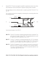
®
E stablished 1981
Advanced Test Equipment Rentals
www.atecorp.com 800-404-ATEC (2832)
1
CDN 117/117-M
CDN 118/118-M
Signal & data line
coupling networks
User Manual
601-142K
CDN 117/117-M
CDN 118/118-M
Signal & data line
coupling networks
User Manual
CDN 117/117-M CDN 118/118-M Signal & data line coupling networks
contentS
1General
1.1Safety
1.2 Safety measures
1.3Installation
1.4 Test execution
2
Functional description
2.1 CDN 117
2.2 CDN 118
3
Test setups
3.1Connections
3.1.1 Coupling modes with differential working generators
3.2 Setup for unshielded interconnection lines with 1.2/50 µs pulse
3.2.1 Coupling setup with 1.2/50 µs pulse
3.3 Test setup for unshielded unsymmetrically operated lines with
1.2/50 µs pulse
3.3.1 Coupling into CDN 117
3.4 Test setup for unshielded symmetrically operated lines with
1.2/50 µs or 10/700 µs pulse
3.4.1 Coupling CDN 118
4
Technical specifications
4.1Dimensions
4.2 Environmental conditions
4.3 Coupling assembly check list
5Maintenance
5.1Warranty
6Addresses
5
5
6
7
8
9
9
11
13
13
14
14
14
16
16
17
17
19
21
21
22
23
23
24
1General
The CDN 117 and CDN 118 coupling - decoupling networks provide a means for
injecting standards-compliant surge pulses into signal and datalines, as well
as telecom lines.
These networks are used in combination with surge generators. Tests can be
performed on equipment, assemblies and installations while they are in operation. These tests and their required coupling methods are prescribed in various
test standards (e.g. IEC/EN 61000-6-2, IEC/EN 61000-4-5).
Specifications and recommendations regarding the execution of the tests, and
their severity, the permissible reaction by the equipment under test (EUT), etc.
can be found in the relevant standards.
The coupling networks with the suffix -M are shipped with a pair of
cables that fit Teseq’s NSG 3000 family generator or Modula. Otherwise, they are identical to the base models.
1.1 Safety
The CDN 117 and CDN 118 coupling - decoupling networks are designed for
operation with high voltage generators, which contain high energy levels.
Incorrect or careless operation can be lethal!
The following safety measures must be strictly and responsibly observed at
all times.
Users must also comply with all safety advice that is provided with generators
that are used with the CDN 117 and CDN 118.
5
6
Neither Teseq AG, Luterbach, Switzerland nor its associated sales organizations
accept any responsibility for personal injury or for any material or consequential
damage resulting from negligent operation of this equipment.
These instruments have been designed in conformity with the relevant safety
regulations and provide all the necessary requirements for safe and reliable
operation.
1.2 Safety measures
These operating instructions form an integral part of the equipment and must
be carefully studied before putting the equipment into operation and must be
available to the user at all times.
WARNING - The equipment must only be used by trained
personnel.
Personnel fitted with a heart pacemaker must neither operate the equipment
nor remain in the test vicinity when the generator is in operation.
These instruments are not designed for use in an explosive atmosphere.
The test equipment is to be set up in conformity with the relevant safety standards (e.g. VDE 104).
The coupling network housing must be properly grounded (earthed).
To ensure safe operation, only approved accessories, plugs, adapters, etc. are
to be used.
The setup must offer insulation protection against voltage which is at least
equal to the pulse voltage.
The pulse voltage must not be able to find its way to ungrounded metallic
objects even if the EUT is faulty or fails.
CDN 117/117-M CDN 118/118-M Signal & data line coupling networks
Depending on the type of EUT and especially on its cabling, a considerable
amount of interference can be radiated which could affect nearby systems
and radio communication. These environmental interference effects to be
controlled by the user through the use of suitable measures such as a Faraday
cage, shielded cable runs, etc.
1.3 Installation
Since the CDN 117 and CDN 118 do not have their own power supplies, they
have not been assigned a protection class. However, they are typically operated
according to protection class 1 in view of their electrical connection to pulse
generators and the metallic parts of their casing.
Local installation regulations must be respected to ensure the safe flow of
leakage currents.
WARNING - Operation without a ground (protective
earth) connection is forbidden!
Operate the equipment only in dry surroundings. Any condensation that occurs
must be allowed to evaporate before putting the equipment into operation. Do
not exceed the permissible ambient temperature, humidity or altitude.
Ensure that a reliable return path for the interference current is provided
between the EUT and the generator. The reference ground plane and the ground
connections to the instruments that are described in the relevant test standard
will serve this purpose well.
These instruments should be opened only by a qualified specialist if specifically
instructed to do so in the operating manual.
7
8
1.4 Test execution
The test area must be organized so that no unauthorized persons have access
during execution of a test. If a safety contact (interlock) is used as a means of
access control to the test area (e.g. Faraday cage), then an additional contact in
series with any hazardous voltages or currents is necessary to provide protection for parts of the EUT that are in danger of being touched.
EUTs, together with their accessories and cables, are to be considered live during
a test. The test generator must be stopped and the EUT supply interrupted
before any work can be performed on the EUT. This can often be achieved by
opening the interlock circuit, depending on the type of generator in use.
The EUT is to be tested only in a protective cage or under a hood which provides
protection against electric shock and all manner of other dangers pertaining
to the particular EUT.
The safety instructions for all instruments and associated equipment in the test
setup are to be observed.
The configuration of the test setup is to be strictly in compliance with the
methods described in the relevant standard to ensure that the test is executed
in a compliant manner.
CDN 117/117-M CDN 118/118-M Signal & data line coupling networks
2 FUNCTIONAL DESCRIPTION
The CDN 117 and CDN 118 coupling - decoupling networks, together with their
accessories, provide a means to inject standardized surge pulses into signal,
data and/or telecom lines.
These coupling networks can be used in situations where the inputs and outputs
of mains-free connection lines must be tested for interference immunity.
The CDN 117 and 118 are designed to be used in conjunction with a surge pulse
generator. They enable tests to be performed on equipment or systems while
they are in operation, by eliminating the attenuation of the surge pulse by auxiliary equipment (AE). The AE must usually be protected by surge suppressors
against the effects of excessively high residual currents. Relevant tests and
coupling methods are described in the test standards IEC/EN 61000-6-1, IEC/
EN 61000-6-2, IEC/EN 61000-4-5, etc.
2.1 CDN 117
The versatile CDN 117 can be used on either unscreened (or unshielded),
unsymmetrically driven signal lines as well as on unscreened signal
and data lines.
The network enables symmetric (line to line) and asymmetric (line to ground)
coupling of 1.2/50 µs hybrid pulses into pairs of conductors.
The test pulse is inductively decoupled from the input side of the CDN (AE
terminals) so that the surge pulse is coupled as fully as possible to the EUT via
the output terminals.
The integral 40 Ω series resistors raise the source impedance of the pulse
generator to 40 Ω. (Since the 2 Ω output impedance of the generator is a
complex quantity, the combined value of the generator plus 40 Ω lies closer to
the required value of 40 Ω).
9
10
Several CDN 117s can be arranged in parallel for applications where more than
two conductors must be decoupled. A special coupling cable is needed.
DC decoupling must be achieved with a coupler type INA 170, INA 171 or
INA 174.
The coupling mode can be changed by relocating the connecting cable from
the pulse generator.
1.6 AT
20 mH
A
in
40 Ω
A’
PE
PE
1.6 AT
20 mH
B
40 Ω
out
B’
Functional schematic of the CDN 117
INA 170 The INA 170 contains a coupling spark gap without a capacitor. The
spark gap has a trigger voltage of 90 V. The coupling element is used
for signal lines with a frequency of over 5 kHz.
INA 171 The INA 171 contains a coupling spark gap with a 0.1 µF capacitor
in parallel. The spark gap has a trigger voltage of 90 V. The coupling
element is used for signal lines with a frequency of under 5 kHz.
INA 174 The INA 174 contains a 0.5 µF capacitor that can be connected in
series with the 40 Ω already incorporated in the coupling network.
This type of coupling element is used for capacitive injection into
unscreened signal and data lines.
CDN 117/117-M CDN 118/118-M Signal & data line coupling networks
2.2 CDN 118
This device is used on unscreened or unshielded, symmetrically driven
telecommunication lines.
The network enables symmetric (line to line) and asymmetrical (line to ground)
coupling of 1.2/50 and 10/700 µs pulses into pairs of conductors.
The test pulse is inductively decoupled from the input side of the CDN (AE
terminals) so that surge pulse is coupled as fully as possible to the EUT.
A high value decoupling choke is required due to the large voltage-time characteristic of the 10/700 µs pulse.
The requisite 100/160 Ω series resistors are arranged in the INA 172 - INA 175
series so that all required modes can be achieved by proper connection of the
INA 370 cable.
DC decoupling can be performed by using either the INA 170 or INA 171 coupling
device.
L1’
L1
A’
in
L2’
L2
PE
B’
PE
L3’
L3
C’
L4’
L4
D’
Functional schematic of the CDN 118
out
11
12
INA 172
This device contains four 100 Ω, 6 W resistors mounted in aplastic
housing equipped with the necessary connectors to achieve all
coupling modes in conjunction with a CDN 118. It is to be used only
with the CDN 118.
R = 4 x 100 Ω
A
B
C
D
Functional schematic of the INA 172
INA 170 The INA 170 contains a coupling spark gap without a capacitor. The
spark gap has a trigger voltage of 90 V. The coupling element is used
for signal lines with a frequency of over 5 kHz.
INA 171 The INA 171 contains a coupling spark gap with a 0.1 µF capacitor
in parallel. The spark gap has a trigger voltage of 90 V. The coupling
element is used for signal lines with a frequency of under 5 kHz.
INA 173 The INA 173 is a short circuit connector to connect a line to ground.
INA 175
This device contains four rugged 160 Ω, 6 W resistors mounted in
a plastic housing equipped with the necessary connectors to achieve
all coupling modes in conjunction with a CDN 118. It is to be used
only with the CDN 118.
CDN 117/117-M CDN 118/118-M Signal & data line coupling networks
3TEST SETUPS
Each test setup should be carefully planned. All the equipment should be
securely positioned, and all cables should be securely connected.
The safety advice given in Sections 1 and 2 and in the generator
manual must be observed. The EUT and the wiring should be handled
only when the generator is not active.
Various test setups and test methods are possible. The following sections
provide examples with more precise details.
3.1 Connections
There are two black safety laboratory sockets on the top left of the CDN 117.
Both lines (L1 and L2) are marked as input and each is protected by a 1.6 A
fuse. These input sockets share a common ground point which is internally
and permanently connected to the housing of the coupling network. The signal
or data lines from auxiliary equipment or loads, such as sensors, detectors,
converters, temperature probes, switching elements, etc., are connected to
these line inputs.
The output (out), to which the EUT must be connected, is positioned on the
right hand side. The EUT could be, a computer, any type of signal amplifier, an
evaluation device or a general type of central system controller.
The common ground socket is connected to the housing.
The pulse connections from the generator are plugged into two of the five high
voltage sockets to obtain the required type of coupling.
13
14
3.1.1 Coupling modes with differential generators
Symmetrical coupling can only be achieved with generators with floating output.
The connection of the coupling network to the high (+) and low (-) outputs of
the generators are shown in the following diagrams.
3.2 Setup for unshielded interconnection lines with 1.2/50 µs pulse
3.2.1 Coupling setup with 1.2/50 µs pulse
Generator
1.2/50 µs
pulse
Auxilliary
equipment
INA 174
L1
IN
Peripherie
L2
1.6 AT 20 mH
CDN 117
1.6 AT 20 mH
Equipment
under test
EUT
40 Ω
40 Ω
OUT
Prüfling
Line to line coupling, line L1 à L2
If the coupling is changed from L2 à L1, then the polarity from the generator
can be swapped.
CDN 117/117-M CDN 118/118-M Signal & data line coupling networks
Generator
1.2/50 µs
pulse
Auxilliary
equipment
INA 174
L1
IN
Peripherie
15
L2
1.6 AT 20 mH
CDN 117
1.6 AT 20 mH
Equipment
under test
EUT
40 Ω
40 Ω
OUT
Prüfling
Line to ground coupling, line L1 à PE
Generator
1.2/50 µs
pulse
Auxilliary
equipment
L1
IN
Peripherie
L2
INA 174
1.6 AT 20 mH
CDN 117
1.6 AT 20 mH
Line to ground coupling, line L2 à PE
Equipment
under test
EUT
40 Ω
40 Ω
OUT
Prüfling
16
3.3 Test setup for unshielded asymmetrically operated lines with
1.2/50 µs pulse
3.3.1 Coupling CDN 117
Generator
1.2/50 µs
pulse
INA 170/171
Auxilliary
equipment
L1
IN
Peripherie
L2
1.6 AT 20 mH
CDN 117
1.6 AT 20 mH
Equipment
under test
EUT
40 Ω
40 Ω
OUT
Prüfling
Line to line coupling with 1.2/50 µs pulse on line L1 à L2
Generator
1.2/50 µs
pulse
INA 170/171
Auxilliary
equipment
L1
IN
Peripherie
L2
1.6 AT 20 mH
CDN 117
1.6 AT 20 mH
Equipment
under test
EUT
40 Ω
40 Ω
OUT
Prüfling
Line to ground coupling with 1.2/50 µs pulse on line L2 à PE
CDN 117/117-M CDN 118/118-M Signal & data line coupling networks
3.4 Test setup for unshielded symmetrically operated lines with
1.2/50 or 10/700 µs pulse
3.4.1 Coupling CDN 118
+ -
INA 172 for 10/700 µs
INA 175 for 1.2/50 µs
Generator
10/700 µs pulse
or
1.2/50 µs pulse
4 x INA 170/171
Auxilliary
equipment
Peripherie
L1
L2
in
L3
L4
4 x 0.5 4 x 20
AT
mH
L1’
CDN 118
L2’
out
L3’
L4’
Equipment
under test
EUT
Prüfling
Line to ground coupling with 10/700 µs or 1.2/50 µs pulse on telecom lines
17
18
INA 172 for 10/700 µs
INA 175 for 1.2/50 µs
+ INA 173
Generator
10/700 µs
pulse or
1.2/50 µs
pulse
4 x INA 170/171
Auxilliary
equipment
L1
L1’
L2
in
L3
Peripherie
4 x 0.5 4 x 20
AT
mH
L4
L2’
out
CDN 118
Equipment
under test
EUT
L3’
L4’
Prüfling
Line to line coupling with 10/700 µs or 1.2/50 µs pulse on telecom lines (1 line
in turn grounded with INA 173)
The INA 172 (4 x 100 Ω) is to be used with a 10/700 µs pulse. Respectively, the
INA 175 (4 x 160 Ω) is to be used with a 1.2/50 µs pulse.
The INA 171 is used for signal frequencies of under 5 kHz while the INA 170
is used as the coupling element for over 5 kHz. Either symmetrical or asymmetrical coupling can be achieved by using the various connectors on the
CDN 118 and INA 172/175. Symmetrical coupling requires a differential generator.
An unavoidable high frequency oscillation will occur when the spark gap in the
INA 171 or INA 170 is triggered. This can disrupt an EUT which has an electronic
memory.
CDN 117/117-M CDN 118/118-M Signal & data line coupling networks
4Technical specifications
Type
CDN 117
CDN 118
Signal line:
Maximum operating voltage AC
DC
250 V
250 V
250 V
250 V
Maximum operating current
1.5 A
0.5 A
Ohmic resistance per path
< 2.5 Ω
3Ω
Decoupling chokes 1 kHz
20 mH +/- 20%
20 mH +/- 20%
Symmetrical stray inductance of a pair @1 kHZ
Not applicable
50 µH approx.
Connectors
4 mm safety banana connectors
Integral resistors
2 x 40 Ω / 6 W
none
Pulse path:
1.2/50 µs pulse
6600 V
6600 V line to ground
3000 V line to line
10/700 µs pulse
not applicable
6600 V line to ground
3000 V line to line
Min. generator impedance 1.2/50 µs pulse
10/700 µs pulse
2Ω
Not permittled
2Ω
15 Ω
Series resistor
2 x 40 Ω, 6 W
none
Maximum pulse frequency
3 per minute
3 per minute
Connectors
5 Fischer type
5 Fischer type
Depending on the impedance setting of the pulse generator, some pulse distortion occurs at the coupler spark gap caused by the inductive loading and the
voltage drop.
The 0.5/700 and 100/700 µs pulses are treated the same as the 10/700 µs
pulses.
19
20
INA 170
10/700 µs pulse
1.2/50 µs pulse
10/700 µs pulse
1.2/50 µs pulse
6600 V
6600 V
40 Ω
40 Ω
3 per minute
1 Fischer type
1 Fischer type
10/700 µs pulse
1.2/50 µs pulse
10/700 µs pulse
1.2/50 µs pulse
6600 V
6600 V
40 Ω
40 Ω
3 per minute
1 Fischer type
1 Fischer type
Maximum pulse voltage
Minimum series impedance
Maximum pulse rate
Sockets
10/700 µs pulse
10/700 µs pulse
6600 V
15 Ω
3 per minute
11 Fischer type
INA 174
Integral capacitor
0.5 µF
Maximum pulse voltage
Minimum series impedance
Maximum pulse rate
Socket
Plug
1.2/50 µs pulse
1.2/50 µs pulse
6600 V
40 Ω
3 per minute
1 Fischer type
1 Fischer type
INA 175
Integral resistors
4 x 160 Ω, 6 W
Maximum pulse voltage
Minimum series impedance
Maximum pulse rate
Sockets
1.2/50 µs pulse
1.2/50 µs pulse
6600 V
2Ω
3 per minute
11 Fischer type
Spark gap 90 V
Maximum pulse voltage
Minimum series impedance
Maximum pulse rate
Socket
Plug
INA 171
Integral capacitor
Spark gap
0.5 µF, 90 V
INA 172
Integral resistors
4 X 100 Ω, 6 W
Maximum pulse voltage
Minimum series impedance
Maximum pulse rat
Socket
Plug
CDN 117/117-M CDN 118/118-M Signal & data line coupling networks
4.1 Dimensions
21
Typ
Housing
Length
Width
Height
Weight
CDN 117
Nickel silver
pressing
260 mm
(10.3 in)
80 mm
(3.2 in)
55 mm
(2.2 in)
2.2 kg
(4.8 lbs)
CDN 118
Molded aluminum
335 mm
(13.2 in)
232 mm
(9.2 in)
180 mm
(7.1 in)
19.5 kg
(43 lbs)
INA 170
Aluminum extrusion
72 mm
(3 in)
25 mm
(1 in)
25 mm
(1 in)
0.06 kg
(0.13 lbs)
INA 171
Aluminum extrusion
72 mm
(3 in)
25 mm
(1 in)
25 mm
(1 in)
0.06 kg
(0.13 lbs)
INA 172
Molded plastics
160 mm
(6.3 in)
160 mm
(6.3 in)
90 mm
(3.6 in)
2 kg
(4.4 lbs)
INA 173
Aluminum extrusion
72 mm
(3 in)
25 mm
(1 in)
25 mm
(1 in)
0.06 kg
(0.13 lbs)
INA 174
Aluminum extrusion
72 mm
(3 in)
25 mm
(1 in)
25 mm
(1 in)
0.06 kg
(0.13 lbs)
INA 175
Molded plastics
160 mm
(6.3 in)
160 mm
(6.3 in)
90 mm
(3.6 in)
2 kg
(4.4 lbs)
4.2 Environmental conditions
Only intended for indoor applications
Ambient temperature
Normal utilization
Storage and transport
+5 ... +40°C
-20 ... +70°C
Relative humidity
20 ... 80%
Nominal working range
reducing linearly above 31°C to 50% at 40°C
Condensation
Not permissible under operation
Altitude
Nominal working range
Storage and transport
< 2200 m
< 12000 m
22
4.3 Coupling assembly check list
CDN 117 Coupling assembly
Set consisting of:
CDN 117
1 ea.
1 ea.
INA 170 coupler with spark gap only
1 ea.
INA 171 coupler with spark gap and capacitor
1 ea.
INA 174 coupler with capacitor
2 ea.
INA 371 coax cable, 0.8 m with connectors (Lemo/Fischer)
4 ea.
Safety laboratory plugs, black
2 ea.
Safety laboratory plugs, yellow/green
1 ea.
Operating manual
CDN 117 – M Coupling assembly
As above but instead of 2 pcs INA 371 supplied with 2 pcs INA 6549 coax
cable, with Fischer connectors fitting Modula and NSG 30xx generator
family.
CDN 118 Coupling assembly
Set consisting of:
1 ea.
CDN 118
4 ea.
INA 170 coupler with spark gap only
INA 171 coupler with spark gap and capacitor
4 ea.
1 ea.
INA 172 matching resistor network, 4 x 100 Ω
1 ea.
INA 173 short-circuit plug (Fischer)
INA 175 matching resistor network, 4 x 160 Ω
1 ea.
4 ea.
INA 370 coax cable, 0.8 m with connectors (Fischer/Fischer)
INA 371 coax cable, 0.8 m with connectors (Lemo/Fischer)
2 ea.
8 ea.
Safety laboratory plugs, black
2 ea.
Safety laboratory plugs, yellow/green
Operating manual
1 ea.
CDN 118 - M Coupling assembly
As above but instead of 2 pcs INA 371 supplied with 2 pcs INA 6549 coax cable,
with Fischer connectors fitting Modula and NSG 30xx generator family.
CDN 117/117-M CDN 118/118-M Signal & data line coupling networks
5maintenance
No maintenance is necessary.
Teseq recommends performing an annual insulation test with a pulse voltage
of 6 kV and open EUT outputs. No arcing or internal breakdown should be
detectable during the test.
5.1 Warranty
Teseq warrants this instrument to be free of defects in materials and workmanship for a period of 1 year, effective from the date of purchase.
During this period, any defective component part will be repaired or replaced
free of charge or, if necessary, Teseq will replace the instrument with one of
equivalent value.
The method of repair/replacement will be at Teseq’s sole discretion.
Excluded from warranty are damage or consequential damage caused by
negligent operation or use as well as the replacement of parts subject to degradation.
This warranty is rendered invalid by any attempt to modify or repair the instrument on the part of the customer or a third party.
The instrument is to be returned in its original packaging. Teseq can accept no
responsibility for damage in transit.
23
Headquarters
Teseq AG
4542 Luterbach, Switzerland
T + 41 32 681 40 40
F + 41 32 681 40 48
sales @ teseq.com
www.teseq.com
Manufacturer
Teseq AG
4542 Luterbach, Switzerland
T + 41 32 681 40 40
F + 41 32 681 40 48
sales @ teseq.com
China
Teseq Company Limited
T + 86 10 8460 8080
F + 86 10 8460 8078
chinasales @ teseq.com
France
Teseq Sarl
T + 33 1 39 47 42 21
F + 33 1 39 47 40 92
francesales @ teseq.com
Germany
Teseq GmbH
T + 49 30 5659 8835
F + 49 30 5659 8834
desales @ teseq.com
Japan
Teseq K.K.
T + 81 3 5725 9460
F + 81 3 5725 9461
japansales @t eseq.com
Singapore
Teseq Pte Ltd.
T + 65 6846 2488
F + 65 6841 4282
singaporesales @ teseq.com
Switzerland
Teseq AG
T + 41 32 681 40 50
F + 41 32 681 40 48
sales @ teseq.com
Taiwan
Teseq Ltd.
T + 886 2 2917 8080
F + 886 2 2917 2626
taiwansales @ teseq.com
UK
Teseq Ltd.
T + 44 845 074 0660
F + 44 845 074 0656
uksales @ teseq.com
USA
Teseq Inc.
T + 1 732 417 0501
F + 1 732 417 0511
Toll free +1 888 417 0501
usasales @ teseq.com
© March 2011 Teseq®
Specifications subject to change
without notice. Teseq® is an ISOregistered company. Its products are
designed and manufactured under
the strict quality and environmental
requirements of the ISO 9001. This
To find your local partner within document has been carefully checked.
Teseq®’s global network, please go to However, Teseq® does not assume
www.teseq.com
any liability for errors or inaccuracies.