1
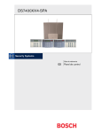
CMS7000 Central Monitoring Software User Manual BOSCH Security Systems Copyright 2001~2004 CMS7000 Table of Contents CMS7000 Ver 1.04 Release Notes-----------------------------------------------------------2 CMS7000 Security System Brief--------------------------------------------------------------3 CMS7000 Security System’s Basic Concept and Glossary--------------------------------4 Hardware Installation and DS7400XI Alarm Panel Settings ------------------------------8 CMS7000 Software Installation---------------------------------------------------------------9 CMS7000 Start and Log in-------------------------------------------------------------------10 CMS7000 Parameter Setting-----------------------------------------------------------------13 CMS7000 Panel Management---------------------------------------------------------------21 CMS7000 Users and Zones Management--------------------------------------------------24 CMS7000 Alarm events Management------------------------------------------------------29 CMS7000 Patrol Management---------------------------------------------------------------36 CMS7000 Database Backup ----------------------------------------------------------------40 CMS7000 Quick Reference------------------------------------------------------------------42 _________________________________CMS7000 User Manual__________________________________ ____ P/N48427E Page 1 BOSCH Security Systems CMS7000 The CMS7000 1.04 Release Note Software install: 1) The database of previous version can not directly add to this version, the UserGroup/User/Zone data can be imported by the Backupmanage.exe, but can’t support the self-define zone type. 2) Before install successful, be sure the USB key haven’t installed. New function: 1) 2) 3) 4) 5) 6) 7) Supporting forward and received alarm data from TCP/IP network. Support notify user by Short Message Service(SMS). Support two DSR32 output port. Log out automatically according the parameter setting. Copy parameter from exist user/zone define. Support Door_Release event of BOSCH_VDP. Support arm/disarm single zone of DS6MX _________________________________CMS7000 User Manual__________________________________ ____ P/N48427E Page 2 BOSCH Security Systems CMS7000 1. CMS7000 Security System Brief 1.1 Configuration The CMS7000 security system is comprised of an alarm sensor, a DS7400XI panel, a DS7412 serial communication module, a DS7445/7447 keypad and CMS7000 security monitor center software. 1.2 Advantages of CMS7000 supervisory software The CMS7000 supervisory software allows the user to manage and maintain the CMS7000 security management system with great flexibility, and is not restricted by the functions of the DS7400XI alarm panel. The zone is defined by the software is separate from the actual zone of the alarm panel. The user can set the conditions for a zone to activate an alarm, how to process the occurring alarm, whether the alarm should be processed automatically, and which map will be displayed. These options make the zone function the most controllable. Security system users can be defined at will. There are no restrictions on the number or location of zones each user owns. Different panels can belong to the same user. The users can be classified to manage with the user group management function. The CMS7000 software provides strong alarm supervisory functions. The status of all the users and all the zones can be monitored through the map, the user/zone table or the Lamp board. Zones with a different status will be indicated with different color or different text. The different types of zones have different Icons that can be defined by the user in the map mode. The icon of the corresponding zone will change appearance while alarming. The detailed information of each zone can be observed through clicking the mouse, and the alarm can be delivered to a user or security management operator through sound, e-mail, or a special output device. The CMS7000 supervisory software provides strong arming/disarming and bypass management functions. One zone, one user, one user group or all the zones can be armed/disarmed (bypass/unbypassed) one at a time. If a zone has trouble or is in a not ready condition, the arm operation will make a system event alarm, indicating a problem with the bypassed zone, and then will continue to arm. An Arm/disarm command from the panel keypad will make the zone arm/disarm automatically. The CMS7000 supervisory software provides Patrol management functions. Users can set any zone as a Patrol check point. There’s no restriction on the Patrol route settings and the Patrol point numbers that each Patrol route passes. The alarm zone that the Patrol route passes through can be set as an automatic bypass zone. So the alarm zone which the Patrol passes through can be automatically bypassed, preventing the Patrol guard from triggering an alarm. The Patrol can be executed separately or it can be executed on a schedule enabling the supervisory software to execute the same Patrol at the same time every day. The Patrol results will be recorded, and the Patrol event can be processed as a system alarm. _________________________________CMS7000 User Manual__________________________________ ____ P/N48427E Page 3 BOSCH Security Systems CMS7000 The CMS7000 supervisory software provides complete system event process functions. It can record the important system events (except for alarm), such as operator’s login, late Patrol etc. The system events are very flexible and can be defined by the user. The CMS7000 supervisory software provides secure management functions. Each operator can be limited by different operation authorities. Each significant operation requires the operator to enter the password, and the operation will be recorded as a system event at the same time. The CMS7000 supervisory software can support DS7400XI alarm panels. The user can set actual zone numbers and partition numbers for each alarm panel in accordance with the actual situation. The software itself does not have restrictions on the number of zones or partitions that are used. In addition, the CMS7000 supervisory system provides data search, printing, complete data protection and backup functions. 1.3 The principle of operation The sensing device installed in the protected area will transmit the received alarm signals, such as smoke, infrared, on/off etc. to the DS7400XI alarm panel. The alarm panel will decide whether it is a fire alarm, burglar alarm or other emergency condition. The panel then will perform any actions that are in its pre-set parameters. The panel then transmits the alarm information to the PC running the supervisory software through the serial communication interface. The supervisory software will process the received alarm event according to the definition of the zone. The DS7400XI alarm panel can operate separately if there is no PC; but the CMS7000 alarm supervisory software must connected to a DS7400XI alarm panel to operate. When the alarm panel reports the alarm event, the supervisory software will change the alarm event to the alarm type defined by user according to the pre-set alarm triggering condition. The software can decide whether the alarm event will be recorded, displayed, printed real time or linked with peripheral equipment according to the defined zone parameter. It can alarm on the supervisory PC with the defined audio file in advance and can notify the user automatically with e-mail. It can also display the user’s corresponding position on the map and on the zone map of the alarming area. When using the CMS7000 supervisory software, some sensors/zones of a DS7400XI alarm panel can be set as a key switch type or a Patrol point type to complete Patrol and arming/disarming operations without a special control keypad. The PC supervisory software of the CMS7000 alarm system can connect with DS7400XI alarm panels The maximum number of alarm zones and partitions that can be connected with each DS7400XI alarm panel does not depend on the supervisory software but depends on the DS7400XI alarm panel type. The CMS7000 software itself does not have restrictions on the number of zones and partitions that can be used. _________________________________CMS7000 User Manual__________________________________ ____ P/N48427E Page 4 BOSCH Security Systems CMS7000 2. CMS7000 Security System Glossary CMS7000 security system: This product is produced by DS. It can be used to safeguard public security, preventing fire, guarding against theft, guarding against intrusion, and can be used for security checks, etc. Its use can be applied for museums, banks and other relevant places. It can be used for the security protection of shops, hotels and residential areas. Alarm sensor: Also known as an alarm detector. It is a sensing device installed in the armed area. It can be used for detection at personnel entrances, or for smoke, fire and other hazards. The sensors used with the DS7400XI system are as follows: DS7450/7452, DS7460, DS7465, MX540, MX775, MX794, MX835, MX934, MX938, MX950, MX280,DS7457,DS3/DS6MX. Alarm panel: Special equipment used to connect to an alarm sensor, to decide alarm status and to manage alarm events. It can be used to set and manage the partitions of alarm panel zones. It also analyses the signal of the alarm sensor, to produce and process alarm events as per the set parameter, and to arm/disarm the zones. It is the core of the whole security system. Generally, the alarm panel is managed, programmed and parameter-set with a keypad. At present the main alarm panel type of the DS7400XI system is the DS7400XI,DS7400XI-EXP. A new version EPROM needs to be installed on the panel to work with the PC supervisory software. The panel must be set up properly for the CMS7000 software to work. The panel parameters have some effect as to how the CMS7000 software operates. Currently each DS7400XI panel can be divided into 8 partitions. Control keypad: Connects with DS7400XI control panel and can be used to program parameters or operate the panel. The commonly used keypads are the DS7445 and the DS7447. One alarm panel can be connected with 10 keypads, and can be expanded to 15 keypads, in which only one keypad can be used to program the panel. This is called the master keypad. Each of the other keypads corresponds to a partition of the alarm panel, and they can be used to operate each partition separately. Keypad user programming: Zone type, partition division, and the operation parameters of the alarm panel all must be set with the control keypad. These settings are called the keypad user parameters. Supervisory software: This software runs on a PC connected to an alarm panel through a serial communication interface. After receiving alarm events from an alarm panel, the software will display alarm information about the zone, and armed/disarmed status. The software can be used for remote arming/disarming of the alarm panel, Patrol management and key switch control. The use of the supervisory software depends on the alarm panel and the parameters set in the alarm panel. Zone of the alarm panel: The signal input unit used to connect with the alarm sensor on the alarm panel. It is distinguished with the zone number of alarm panel, starting from No.1. The corresponding relationship between the zone number and the sensor connecting point number of the alarm panel can be set through the alarm panel. _________________________________CMS7000 User Manual__________________________________ ____ P/N48427E Page 5 BOSCH Security Systems CMS7000 Zone type of the panel: Determines what type of classification the panel gives to an alarm signal, for example, fire zone, burglar zone, 24h silent zone, etc. The zone type can be different then the physical zone. The zone type is set in the alarm panel. Partition of the alarm panel: The relevant zones can be classified into physical partition groups. The arming/disarming operation of the alarm panel is actually arming/disarming the physical partition. The zone cannot be armed/disarmed directly. One DS7400XI alarm panel can manage 8 physical partitions, so one DS7400XI alarm panel can support up to 8 users who have separate arming/disarming authority. The CMS7000 supervisory software should be used when there are many users and each user manages few zones. Arming/disarming at the panel: The arming and disarming functions are supported by the DS7400XI panel. Some types of alarms, such as a burglar alarm, will happen only under an armed condition. The DS7400XI alarm panel’s arming/disarming can only be operated in the physical partition of the unit. Alarm event of the Panel: After the alarm is triggered, the panel processes the alarm event according to the parameter set on alarm panel. Then it can report the alarm event to the PC supervisory software through the DS7412 serial communication module. Several events can be produced by the panel with one physical alarm, for example, a panel may produce four alarm events when a zone which is set as a physical fire zone is triggered: zone on short, fire alarm, zone on open and zone reset. It can also produce two alarm events: zone on short and zone on open when a 24h zone alarms. Panel configuration: The parameters about the panel which is connected to the PC running the CMS7000 software. The panels must have unique panel numbers. The Panel name is defined by the operator in software for easier management. It is recommended that panels have different names. The serial interface for each panel must be different. The user can set the communication parameters (such as baud rate and check means). The partition number and zone number each panel supports can be set by the user according to the actual situation, but the minimum number should be 1. Panel zone number: The number of the zone (sensor) that corresponds to each panel. Each panel has a unique number. A panel and a panel zone together correspond to a unique zone of CMS7000. Panel partition number: The basic unit of each alarm panel’s arming/disarming management and its collection of panel zones. Each DS7400XI panel can support a maximum of 8 zones at present. A partition is not suitable to use when there are many users and few user groups. So it is only used for physical arming/disarming of panels in the supervisory software. Zone: The basic unit of the management system and it is the core of the whole system. One zone corresponds to one alarm sensor. Its operation mode depends on the setting of the zone parameters. _________________________________CMS7000 User Manual__________________________________ ____ P/N48427E Page 6 BOSCH Security Systems CMS7000 Triggering condition: The zone will alarm according to the set conditions. The triggering condition is the panel alarm event that is transmitted to the PC supervisory software through the serial interface while the alarm panel is alarming. Alarm information will vary from one panel to another panel even for the same kind of alarm. A panel may also produce four alarm events when a physical zone that is set as a fire zone is triggered to alarm: zone on short, fire alarm, zone on open, and zone reset. When the panel receives the triggering information of a corresponding panel zone, it sends this information to the PC supervisory software. This zone will be regarded as the alarming zone and other types of information will be ignored. One zone can only correspond to one triggering condition. So the panel number, the panel zone number and the panel information together determine only one alarm. Patrol zone: This is a special zone. The alarm signal of this zone type will not be processed as an alarm in the PC supervisory software. It will be used to present the stipulated check point the Patrol guard will reach. Key zone: This is a special zone. The alarm signal of this type zone will not be processed as an alarm in the PC supervisory software, but will be used to control the al arming/disarming of the zone. So the user can carry out al arming/disarming with the ordinary switch, in this condition without using the control keypad. User: Some zones can be classified to one group for unified management. Each zone must belong to some user. User group: For easy management, users can be classified to different user groups. Each user must belong to some user group. Map: The map used to monitor the zone and the user. The operator can appoint the map file name that each zone and each user belongs to, and can orient their position on the map. All users defined on the appointed map will be displayed if the user mode is selected while displaying the map. All zones on the appointed map will be displayed if the zone mode is selected. There is a main monitor map that the system can switch automatically, to monitor the user within the stipulated time. Operator: The user of the supervisory software. The operator level determines their authorities. They can process alarms, arm/disarm, execute Patrol management. The operator’s login/logoff and any other operations will be recorded as a system event by the supervisory software. Arming/disarming: Arming/disarming the zone has nothing to do with the arming/disarming status of the alarm panel. The supervisory software will determine whether to process the received panel alarm information conforming to the arming status of the zone, the zone type etc. _________________________________CMS7000 User Manual__________________________________ ____ P/N48427E Page 7 BOSCH Security Systems CMS7000 Patrol management: The Patrol route, including the Patrol point and the auto-bypassed alarm zone should be set first. There is no restriction on the number of Patrol points and the auto-bypassed alarm zones. The absolute time from the beginning of the Patrol to reach the Patrol point (not the time from the last Patrol point to this Patrol point) is the allowable time tolerance and should be set. The auto-bypassed beginning/ending time (the absolute time calculated from the beginning to Patrol) should be set. The Patrol beginning time is not set in the Patrol route but depends on the Patrol plan execution. There are two Patrol plan executions, manual execution and automatic execution. All should set the Patrol beginning time, the Patrol route and the Patrol guard group. The manually executed Patrol plan can be executed immediately or executed at a fixed time. The automatically executed Patrol plan is the Patrol plan that is executed at a fixed time everyday according to the setting in the automatic Patrol plan pool. The Patrol results cover “reaching Patrol point normally”, “reaching Patrol point late”, “reaching Patrol point abnormally”, “Patrol point cancellation”, “Patrol plan over”, “Patrol plan cancellation”, etc. How to process each situation can be set in the system event type. Patrol point: The passed check point while Patrolling. The Patrol guard can trigger this alarm point to inform the supervisory system that the Patrol of that area is complete. Patrol route: Used to restrict the passed Patrol point and the completed time while Patrolling. The Patrol guard should Patrol along this route. Some zones can be set as auto-bypassed zones. Patrol group: Group of Patrol guards. Current executing Patrol: It all depends on the Patrol route, Patrol group, Patrol beginning time, and it can be cancelled. The Patrol can be executed automatically as scheduled everyday or it can be executed manually. _________________________________CMS7000 User Manual__________________________________ ____ P/N48427E Page 8 BOSCH Security Systems CMS7000 3. Connected with the Panel 3.1 CMS7000 Panel zone partition dividing and managing The zone type of the DS7400XI alarm panel depends on the connecting sensor type, and should be set through the master keypad. See the DS7400XI Panel User Manual for details. The division of partitions and zones can be set according to the user’s actual need and they do not have a large affect on the actual use. It is recommended that the zone alarm should reset automatically following the zone reset signal, and the address 0000: D2=1(or 4). 3.2 Panel communication parameter and operation mode The DS7400XI panel and PC are connected together with an RS232 serial communication interface through the means of DTE-DTE. The communication rate is 2400bps. Panel operation mode should be set as 18. Addr: 4019 D1=1 D2=8 Addr: 4020 D1=2 D2=5 Notice: the dial set of the phone should be turned off if it is not connected with other equipment through the phone. 3.3 VIDEO DOOR PHONE The VIDEO DOOR PHONE communication parameter is 9600, 8, 1, none, software _________________________________CMS7000 User Manual__________________________________ ____ P/N48427E Page 9 BOSCH Security Systems CMS7000 4. CMS7000 Software installation 4.1 Prepare before installation Before installation the CMS7000 software, the PC need more than PII400,128M RAM, 4G HDD. Be sure have not install the USB key hardware before the software install success. The CMS7000 need a key when running, it decide how many zones that the software support, be sure the key install OK at the USB port or PRN port of your PC and you can install the Printer to it. 4.2 Software installation The CMS7000 will automatically install once the setup.exe file is selected. The user will need to answer a small number of questions and then the software will complete the installation. The BDE management program can not be running during installation. Any program that is running the BDE program should be closed. The PC should be restarted upon installation. The real time printing function may fail if a directory name in the installation route is longer than eight characters. _________________________________CMS7000 User Manual__________________________________ ____ P/N48427E Page 10 BOSCH Security Systems CMS7000 5. Starting CMS7000 and Log In 5.1 Starting the CMS7000 Click The CMS7000 icon to start the program. The login interface will appear. Figure 1: Login Interface 5.2 Checking the authority of the CMS7000’s operator (see the figure) In order to ensure the safety of the system, the user can own the corresponding operation authority only after logging in. Initially, there is a supervisor who has all authorities in the installed system. Adding users and the authority settings are managed by the supervisor. The initial password of the supervisor is NULL. NOTE: Be sure to change this password after the initial set-up. Figure 2: Authority Setting Figure 2-2: Authority Checked _________________________________CMS7000 User Manual__________________________________ ____ P/N48427E Page 11 BOSCH Security Systems CMS7000 5.3 CMS7000 user interface (see the figure) The CMS7000 will run in full screen. The user interface includes the main display interface, popup window, system menu and toolbar. The main display interface will display the alarm board, user/zone map, user zone information, Patrol management, alarm history record, and other data. Tool buttons are used to switch between the windows. All functions of the CMS7000 have the corresponding option in the system menu, and the most commonly used functions are listed in the toolbar. Figure 3: User Interface _________________________________CMS7000 User Manual__________________________________ ____ P/N48427E Page 12 BOSCH Security Systems CMS7000 The basic operation. ToolBar Menu Password checked _________________________________CMS7000 User Manual__________________________________ ____ P/N48427E Page 13 BOSCH Security Systems CMS7000 6. Parameter Setting of CMS7000 Used to set parameters related to the CMS7000 software operation status. The system parameter can be modified only after clicking the “modify” button. 6.1 CMS7000 Operator Authority Management 6.1.1 Operator authority management interface (see the figure) 6.1.2 Procedures Selecting the operator: Select the operator in the operator list. Modifying: Change the name of the operator, contact means and authority, then click the “OK” button. _________________________________CMS7000 User Manual__________________________________ ____ P/N48427E Page 14 BOSCH Security Systems CMS7000 Changing the user’s password: Input the original password, the new password and the confirmation then click the “OK” button. The password cannot be modified if the original password is not correct, or the new password is not the same as the password entered while confirming. 6.1.3 Description of authority: The operator has this authority if the operation authority has the label of “√”. The control of the operation authority is realized through restricting on the operation interface display. The user cannot open the corresponding operation interface unless he has the corresponding operation authority. 6.2 CMS7000 Zone Type Default Attribute Setting The CMS7000 uses a zone to manage alarms, Patrolling, arming/disarming and other events. Different types of zones determine if there should be a different process method when a zone alarms. The zone types are fixed, but the user can set their attributes. The zone type determines the default attributes of the zone, but the attribute of each specific zone can be modified. So the same type of zone can have different attributes. The default type of the zone just provides a general default parameter. 6.2.1 Zone type interface setting (see the figure) The parameter of a zone type determines the initial default of the zone, when a zone is defined. As in this type of zone. Figure 8: Zone Type Setting _________________________________CMS7000 User Manual__________________________________ ____ P/N48427E Page 15 BOSCH Security Systems CMS7000 6.2.2 Parameter description of the zone type Name of the zone type: The name of the zone type is used to distinguish different types of zones. There are five types of zones for the CMS7000: Patrol zone, arming/disarming switch zone, emergent help zone, fire alarm zone and burglar alarm zone. The alarm event of a Patrol zone will be regarded as a Patrol check signal. The alarm event of an arming/disarming switch zone will be regarded as an arming /disarming command of the other zones. The Emergent help, fire alarm and burglary alarm will be processed as alarms. Triggering condition: The alarm panel will determine whether to alarm or not according to its parameter setting after it receives the signal from the sensor. Many alarm events can result in an alarm, such as: fire alarm, including short circuit, reset, zone reset. The alarm panel will report “short circuit” and “reset” as two alarm events if it judges that the fire sensor is mis-triggered. The alarm panel will not process all received alarm events, but will determine to process the alarm event or not according to its triggering condition. If the triggering condition of the fire type zone is a fire alarm, fire alarm type zone will be triggered only when the DS7400XI alarm panel reports the happening fire event. The CMS7000 will ignore the short circuit alarm event resulting from being mis-triggered. If the triggering condition of the fire alarm zone is short circuit alarm, the CMS7000 software will regard _________________________________CMS7000 User Manual__________________________________ ____ P/N48427E Page 16 BOSCH Security Systems CMS7000 any short circuit alarm event as a fire alarm and process it accordingly. Under this circumstance the short circuit alarm event will be regarded as a fire alarm and will be processed by the CMS7000 software even though the corresponding zone of DS7400XI alarm panel is set as 24h zone. Away delay: If the user thinks it is necessary to arm the zone when he is away, the alarm may be triggered before he exits, after the zone is armed. The information of the alarm triggered by the user himself within the delay time will be ignored by the CMS7000 if the zone has away delay setting. The alarm event will be processed only when it passes the time of the away delay setting. Entry delay: The alarm event will be triggered when the user enters the zone. The CMS7000 will alarm after it receives the alarm event if the zone isn’t disarmed within the entry delay (if the entry delay is more than zero). The CMS7000 will look at the alarm event as the alarm is activated by the user and ignore it if the zone is disarmed within the entry delay. Alarm audio file name: The CMS7000 will display the alarm information and will play the alarming sound according to the set alarm audio file name after the alarm has been confirmed while alarming. Font color: Different types of alarm information can be set to display in different font colors. Background color: Different types of alarm information can be set to display in different font background colors. Informing user: If the setting of the informing user is valid and the local e-mail box of system setting is correct, the CMS7000 will send the alarm mail automatically to the e-mail address according to the user information of the zone. Alarm display: The alarm display setting determines whether the alarm information will be displayed in the alarm process window, to remind the operator of processing the alarm after the alarm is sent. Alarm saved: The alarm saved setting determines whether the alarm will be saved to history database, when alarm display is disabled, it means that the alarm will directly save to history database without process. Real time printing: The alarm information will be output through to the printer while alarming if the real time printing setting is valid. DSR32 output linkage: CCTV can be linked while alarming (still not realized). 6.2.3 Selecting the zone type to be modified The zone type to be modified should be selected first while changing the zone type parameter. Select the zone type in the zone types list at the top of setting window. _________________________________CMS7000 User Manual__________________________________ ____ P/N48427E Page 17 BOSCH Security Systems CMS7000 6.2.4 Changing the zone type picture 6.2.5 Audio alarm setting Click the “folder” button on the right of the “alarm audio file” in the zone type parameter, the dialog box of the audio file name to input will appear. The audio file name can be input directly or clicking the “folder” button on the right of the audio file name inputting box again. The dialog box of the “standard file” will appear, then select the audio file from the disk. The audio file must be saved in the RES subdirectory of the CMS7000 installation directory. 6.2.6 Setting the alarm display color The alarm display font color and the font background color can be set. Upon unlocking, the “standard color”, the dialog box will appear after double clicking the “color edit” box, then select the required color. 6.3 The system event default attribute setting 6.3.1 Interface of system event define The CMS7000 can manage the alarm sent by the DS7400XI alarm panel. In addition, it can process some events happening while the software is running, such as recording the login/logoff of an operator, the time and the operator’s name of the arming/disarming operation, reaching the Patrol point on time and etc. All these are system events defined by the CMS7000. _________________________________CMS7000 User Manual__________________________________ ____ P/N48427E Page 18 BOSCH Security Systems CMS7000 6.3.2 Description of the System Event Parameter The System event item and the name cannot be modified. System event processing: The default process method while a system event is occurring. DSR32 linkage data: The data output through the DSR32 while alarming. Allowing real time printing: The system event will be printed while a system event is occurring. 6.4 System parameter setting 6.4.1 Automate operation 6.4.2 Email system setting 6.4.2.1 Local mailbox setting The Local mailbox must be set in order to inform the user with e-mail when an alarm event happens. The e-mail will be sent by the owner of the local mailbox. The local mailbox only supports the SMPT format. _________________________________CMS7000 User Manual__________________________________ ____ P/N48427E Page 19 BOSCH Security Systems CMS7000 Figure 6: System Parameter—Email Server Setting 6.4.2.2 Mail template setting The alarm mail form to inform the user can be set through the mail template setting. The mail subject can be used to set the mail subject for alarms (some mail servers do not support the mail subject with Chinese characters). The mail content can be entered at will. The relevant parameters can be used through clicking the relevant buttons on the right, then the descriptive characters which could not be modified will appear in the mail template. And then the relevant mail content will be substituted by the actual parameters while sending. Figure 7: System Parameter—Email Template Setting 6.4.3 Linked output interface setting The linked output interface will be used to send linked data to the peripheral linked equipment through the serial interface when the zone alarms. The linked data should be set in the zone parameters. * Be careful the linked interface setting cannot be the same as the alarm panel interface setting. _________________________________CMS7000 User Manual__________________________________ ____ P/N48427E Page 20 BOSCH Security Systems CMS7000 6.4.4 Automatic login interval/map, auto-switch interval The CMS7000 allows the user to define a map as the main supervisory map while using a map to monitor the armed area. The supervisory window will switch to the main supervisory map automatically within the stipulated time. 6.4.5 Auto-backup setting The data can be backed up through the menu and the toolbar. In addition, the auto-backup parameter in the system parameter can be set to back up data automatically. The auto-backup interval can be a time or it can be several alarm history records. The backup catalogue must be set. The auto-backup can be stopped. _________________________________CMS7000 User Manual__________________________________ ____ P/N48427E Page 21 BOSCH Security Systems CMS7000 6.4.6 Alarm Process Result 6.4.7 Arm/DisArm automatically _________________________________CMS7000 User Manual__________________________________ ____ P/N48427E Page 22 BOSCH Security Systems CMS7000 7. Panel Parameter Setting 7.1 Panel parameter setting interface The Panel parameter setting is mainly used to set the communication parameters of the PC software and the DS7400XI alarm panel. For easy management of alarm panels, alarm panel name, panel supervisor, contact means etc. 7.2 Description of panel parameter Panel number: Each DS7400XI alarm panel connected to the PC has a unique number, and the panel number should not be repeated. The software supplies the number, so the user does not need to enter it. Panel name: Each DS7400XI alarm panel connected to the PC has a unique name for easy memory and management. _________________________________CMS7000 User Manual__________________________________ ____ P/N48427E Page 23 BOSCH Security Systems CMS7000 Minimum zone number: The minimum allowable zone number and the maximum allowable zone number of the DS7400XI alarm panel, together determine the total number of zones that can be connected to a DS7400XI alarm panel. It should be set according to the actual situation of each DS7400XI alarm panel. Maximum zone number: The maximum zone number that can connect with the DS7400XI alarm panel. Minimum partition number: The minimum allowable partition number and the maximum allowable partition number of the DS7400XI alarm panel together determine the number partitions that can connect to the DS7400XI alarm panel. The DS7400XI alarm panel should be armed/disarmed by taking the partition as a unit. One DS7400XI alarm panel can only support 8 partitions the at present. The DS7400XI alarm panel should be used together with the CMS7000 software when there are more than 8 partitions that need to be supported by one DS7400XI alarm panel. The partitions of the DS7400XI alarm panel do not have much affect on using the CMS7000 software. They do have an affect on the remote PC arming/disarming functions of the DS7400XI alarm panel through the CMS7000 software. Maximum partition number: The maximum partition number that DS7400XI alarm panel allows. Panel supervisor: The supervisor name of the alarm panel. Contact means of supervisor: Includes the contact phone number and e-mail address. Communication parameter: The parameter of the serial interface communication includes baud rate, checksum, data bits, stop bit length etc. Its setting must conform to the corresponding DS7400XI alarm panel, or it will not work. Communications will fail if one serial interface is used by several panels. 7.3 Operation Procedures Unlock Click the “Edit” button to unlock the locked parameter when opening the panel parameter modification interface, then the function button will be available. The previous panel parameters can be modified or new panels can be added. Adding a panel, modifying/deleting panel parameters To add a new panel: Click the “add” button, the blank panel parameter form will appear. Fill in the form according to the actual situation, any option with the “*” must be filled. To modify a panel parameter: Select the panel to be modified on the top form, then change the relevant parameter. “OK” and “Cancel ” buttons will be available after modifying the parameter. _________________________________CMS7000 User Manual__________________________________ ____ P/N48427E Page 24 BOSCH Security Systems CMS7000 To delete the current panel: Select the panel to be deleted first, then click the “delete” button. The deleted panel can not be restored. Note: the modification can not be done in the form on the top. Save/cancel the modification After modifying, the modified or added panel parameters will be saved if the “OK” button is clicked, and they will be cancelled if the “Cancel” button is clicked. The “OK” operation will be executed automatically if another panel is added or another panel parameter is modified. So another panel should not be selected unless the modification is completed. 7.4 Communication interface supervision The data received from the serial interface can be supervised through the communication interface. The received information will be displayed if the connection of the hardware is correct, this window will display the relevant alarm event when the alarm panel is triggered if the communication parameters of the alarm panel are set correctly. _________________________________CMS7000 User Manual__________________________________ ____ P/N48427E Page 25 BOSCH Security Systems CMS7000 8. Management of the CMS7000 User and Zone 8.1 The relationship among user group and user zone A zone corresponds to the real zone of the DS7400XI alarm panel. The owner of the zone is the user. One user can have several zones, and these zones can belong to different DS7400XI alarm panels. Different users can form the user group for easy arming/disarming management. 8.2 User group setting The user group setting is mainly used to set the user group name, and each user must belong to some user group. _________________________________CMS7000 User Manual__________________________________ ____ P/N48427E Page 26 BOSCH Security Systems CMS7000 8.3.1 The Interface of User setting User setting interface see the figure 8.3.2 Description of user attribute User name: the user name is a symbol to distinguish different users, and user names should not be repeated. Contact person: the name of the contact person. Communication means of the contact person: including phone number/numbers (there can set four phone numbers) and e-mail address. The user group: The user group that the user belongs to must be set in the user group setting window. Each user must belong to a user group. User map: The map file name should be appointed if it is necessary to use a map to describe a user position. The user position in the map should be oriented with the map orientation function. User address: It is the word description of the user address. 8.3.3 User attribute setting Click the “delete user” button to delete the selected user. The zone that the deleted user belongs to will be deleted automatically. Make sure that there is no zone belonging to the deleted user on the Patrol route, this will prevent errors from occurring in future Patrols. _________________________________CMS7000 User Manual__________________________________ ____ P/N48427E Page 27 BOSCH Security Systems CMS7000 8.4 Zone management 8.4.1 Interface of zone setting zone setting interface see the figure 8.4.2 Parameter description of zone User the zone belongs to: It should only be selected from the input users. Each zone must belong to some user. Zone name: It is the word description of the zone name. It is a symbol distinguishing different zones, and zone names should not be repeated. Zone type: It is the type of a zone, and should be selected only in the zone types defined by the user. It has nothing to do with the zone type of the DS7400XI alarm panel. Parameters of a zone will be reset automatically according to the default parameter of zone type while changing a zone type. Corresponding panel: The actual DS7400XI alarm panel that the zone corresponds to should only be selected from the set panel during panel setting. Corresponding panel zone: It is the alarm zone number of the DS7400XI alarm panel that corresponds with the zone. The alarm panel and the panel zone determine the corresponding alarm sensor for that zone. Corresponding panel partition: The partition in alarm panel, it is the panel partition that corresponds to the partition. Triggering condition: The condition that the zone will produce alarm information. The zone may receive different types of alarm events from the corresponding panel zone, but only the alarm event conforming to the triggering condition will be regarded as the alarm, and will be analyzed and _________________________________CMS7000 User Manual__________________________________ ____ P/N48427E Page 28 BOSCH Security Systems CMS7000 processed. The triggering condition is exclusive, and other alarm events will be ignored by the zone. Alarm point position: The word description of the sensor installation position in the corresponding zone. Zone map: The position management of the zone, it can be realized through naming the map for that zone. The position of zone on the map can be determined through the orientation operation. Alarm sound: The sound alarming can realized on the PC when the zone alarms. The alarm sound can be recorded in audio file in advance. Entry delay: If the zone has set the entry delay and the alarm is detected, the alarm will be ignored if the zone is disarmed within the entry delay period. The alarm will be triggered if the zone is not disarmed within the entry delay period. Away delay: After arming, the alarm will be ignored if the alarm is triggered within the delay period. The triggered alarm will be processed if the away delay period has expired. Alarm pre-processing: It is the alarm pre-processing scheme. This scheme will be displayed in the alarm process window if the alarm information is displayed. This scheme will be automatically saved as an alarm process result if an alarm is not displayed. DSR32 output data: The linked data will be output through the set linkage output interface while alarming if the linkage setting of the peripheral equipment is correct. 8.4.3 Zone parameter setting Click the user whose zone parameter needs setting in the users list. All the zones of the selected user will be displayed in the zone list. Select the zone that needs modification from the zone list. The unused panel zone can be listed separately while selecting the panel zone. Different zones are allowed to correspond to the same panel zone. The zone will transfer to the new user. If the user name and the zone/zones belong to changes to another user name while modifying the parameter of a zone. Click the “add” button to add a zone. For the new zone, the items with “*” must be set, or errors will occur. Click the “del” button to delete a zone. Make sure that the deleted zone is not passed by the Patrol route or errors will occur during future Patrols. The controlled zone will be automatically reset when the arming switch type zone is deleted. 8.5 User/zone map orientation _________________________________CMS7000 User Manual__________________________________ ____ P/N48427E Page 29 BOSCH Security Systems CMS7000 If the user or the zone has appointed the map files, their position on the map can be set for monitoring. 8.5.1 Operation procedures Clicking the map orientation menu or the toolbar to open the map orientation window. Unlocking orientation: Click the “unlock” button to unlock prior to map orienting. Map linkage setting: Display the map the user/zone belongs to prior to map orienting. The map display in the user/zone trees, the user/zone belongs to can be selected only when the map linkage setting is valid. Zone/user orientation: The user/zone icon can be pulled to the new position directly on the map if the user/zone has been oriented on the map. The user/zone that is not oriented can be oriented by pulling it to the map from user/zone tree for orienting. _________________________________CMS7000 User Manual__________________________________ ____ P/N48427E Page 30 BOSCH Security Systems CMS7000 9. Alarm Supervisory and Processing 9.1 Alarm supervisor 9.1.1 Armed area supervisory The alarm will be displayed in the alarm process window. In addition, the CMS7000 can monitor the status of the armed area at any time. 9.1.2 Status table supervisory The status of all the zones can be monitored through the status table to examine whether the zone is bypassed, armed or alarmed. The basic information of the zone can be examined through clicking the alarm board. Click the right button can active the popup menu. 9.1.3 User/zone map supervisory The basic status of the user or the zone can be examined through the supervisory map if the map file appointed by user or zone has been oriented on the map. Only one map can be monitored at any one time. The monitor is what the map depends on whether that map is linked with the alarm map or the map orientation. If the alarm map of a zone is linked and it alarms, the monitored map will switch to the map of the alarming zone while selecting the alarm item in alarm list of alarm process _________________________________CMS7000 User Manual__________________________________ ____ P/N48427E Page 31 BOSCH Security Systems CMS7000 window. All the zones defined on this map will be displayed. The monitored map will switch to the alarmed map if zone is not defined. If the map linkage setting is valid, the supervised map will switch to the corresponding alarm map while selecting the user or the zone in the users/zones tree on the right of the map orientation window. The system will automatically switch to the main supervisory map if there isn’t any operation done to the map display area within the set time. See the system parameter setting for the main supervisory map and switch the time settings. 9.2 CMS7000 Arming/Bypass Management 9.2.1 Zone status Arming/disarming is an important concept of the security system. The sensors of some zones will be triggered only under the arming condition. Under the disarming condition, those sensors will not alarm even if the sensors are triggered. For example, if the security system is kept under the arming status when the owner is in, it will not alarm when the burglar sensor detects the user himself. If the security system is set under the arming status when the owner is out, it will alarm when the burglar sensor detects there is somebody else there. For some types of alarms, it will alarm once the sensor is triggered regardless of the arming/disarming status, such as a fire alarm. Zone of the Panel status and Zone of CMS7000 status. The DS7400XI alarm panel can be used to arm/disarm the panel zone by taking the panel partition as a unit. The 128 zones can be divided into 8 partitions by the DS7400XI alarm panel at present, so the DS7400XI alarm panel can support a maximum of 8 arming/disarming units. It is not suitable in a case that there are many users and few zones per user. The CMS7000 software also can be used to arm/disarm the zones defined by the software, because it can be used to arm/disarm user groups as well as a single zone. There is no restriction on the total number of users and the zone number each user owns, so the CMS7000 software management is more flexible than the DS7400XI alarm panel. As a result, the panel arming/disarming and arming/disarming are two different concepts. The panel arming/disarming status determines whether the DS7400XI alarm panel produces alarm information, and the zone arming/disarming status of the CMS7000 software determines whether the information the DS7400XI alarm panel receives will be processed. Some zones of the DS7400XI alarm panel will alarm only when the panel is kept in an arming status. The CMS7000 supervisory software runs on the basis of the alarm information of the alarm panel and the arming/disarming of CMS7000 will not produce an actual affect if the alarm panel does not arm. Bypass The zone can be kept in a bypass status with the CMS7000 software. The alarm will not be processed if both the bypass and the “bypass status affect” attribute of zone are valid. The bypass disabled while disarm the zone of CMS7000. _________________________________CMS7000 User Manual__________________________________ ____ P/N48427E Page 32 BOSCH Security Systems CMS7000 9.2.2 Parameter selecting for arming/disarming Select the range to operate (all users, user groups, users and zones first) then click the corresponding operation button. Bypass and arming/disarming interface All the statuses of the zones will be displayed in the tree-structure. Green means that the zone status is in operation. Yellow means that the zone status is normal but is not in operation. Red means that the zone status is bypassed or in trouble operation. The detail operation option will appear through clicking the right key of the mouse when the mouse moves within the status tree. 9.2.3 Arming/disarming description The arming has three types: away arming, home arming and normal arming. The away arming operation will affect only the zone that has set the “away arming valid”. The home arming operation will affect only the zone that has set the “home arming valid”. These two arming operations will affect the status of the zones that were set “away arming valid” and “home arming valid”. The normal arming operation will arm/disarm the operation object compulsorily. _________________________________CMS7000 User Manual__________________________________ ____ P/N48427E Page 33 BOSCH Security Systems CMS7000 9.3 CMS7000 Alarm Processing The zone alarm will be triggered if the alarm condition is met after the CMS7000 receives an alarm event from the DS7400XI alarm panel. The alarm information of an occurring system event will be displayed in the alarm window if the “alarm display” attribute setting of zone is valid. Different types of alarm information will be displayed in different colors according to the parameter set in the zone type setting. Then, how to process the alarm information depends on the “alarm save” parameter and the “alarm display” attribute setting of the zone. The alarm information will be saved automatically in the history record database only the if the “alarm save” or the “alarm display” attribute setting is valid. The alarm will only be displayed and the process result will not be saved in the history record database if the “display alarm” setting is valid but the “save alarm” setting is not valid. 9.3.1 Alarm display/process interface (see the figure) Figure 10: Alarm Display/Process Interface _________________________________CMS7000 User Manual__________________________________ ____ P/N48427E Page 34 BOSCH Security Systems CMS7000 9.3.2 Alarm display/process procedures Double click the corresponding information in the alarm list. The detail information in the display window will appear when the alarm information or the system event of the zone appears in alarm window. Then the detail alarm information can be processed accordingly. The alarm information can be processed rapidly by moving the mouse to the bottom of the alarm list the rapid process window will appear automatically. The process scheme of the alarm information is set in the zone parameter setting or the system event type parameter setting in advance, and the process result should be entered by the operator according to the actual process result. The current alarm can be processed through clicking the “process” button. The system alarm information and the process result will be saved in the history event database. Then the current alarm information will be deleted if the “save alarm” parameter setting of zone or the “save alarm” setting of system event type parameter is valid. The alarm display window will be closed automatically after the last alarm information is processed completely. 9.4 Alarm History Record Management All of the event will be record to the history database, the CMS7000 have three types of events, first is alarm event, second is system event, the third is operation record. After packed the current alarm history table, the record will be store to another database for every month, the number remain in current database define at system parameter setting. You ‘d better do history pack every month. _________________________________CMS7000 User Manual__________________________________ ____ P/N48427E Page 35 BOSCH Security Systems CMS7000 If you want to list another history record that have not in current database, you need to use the history query function, at the history query form, you can query history record by different condition and select different database. _________________________________CMS7000 User Manual__________________________________ ____ P/N48427E Page 36 BOSCH Security Systems CMS7000 10. CMS7000 Patrol Management The Patrol management is mainly used to manage and monitor the security personnel’s Patrol. Generally some zones of the DS7400XI alarm panel can be connected with the Patrol check equipment. The Patrol guard can use the Patrol check equipment when he reaches the position of the installed equipment (namely the Patrol check point). The alarm event triggered in the corresponding zones of the DS7400XI alarm panel and the Patrol check equipment will be sent to the CMS7000 software. Then the zone corresponding to the type for the alarm panel zone is set as the Patrol point zone type. So the alarm information processed will not be as alarm information but as Patrol information. 10.1 Patrol management principle In General the Patrol should wait for the Patrol guard to reach the Patrol point in an allowable timeframe. The time of the Patrol should not be a definite time but a period of time. There are three types of Patrol results: “reaching Patrol”, “not reaching Patrol” and “abnormal Patrol”. It is a “reaching Patrol” if there is a corresponding plan in the Patrol plan when a Patrol event is triggered. It is an “abnormal Patrol” if there is no corresponding plan when a Patrol event is triggered. It is a “Not reaching Patrol” when no Patrol event conforming to the condition happens within the allowable timeframe of the Patrol plan. The Patrol guard may trigger an alarm because he may pass a burglar alarm zone while Patrolling. So the CMS7000 can automatically set/clear the bypass zone for some zones while Patrolling. _________________________________CMS7000 User Manual__________________________________ ____ P/N48427E Page 37 BOSCH Security Systems CMS7000 10.2 Patrol point definition According to the actual situation, the zone to be used for the Patrol check should be defined as a Patrol point type zone. 10.3 Patrol route setting The Patrol route must be set first prior to Patrolling, including setting the Patrol point and the autobypassed zone. Patrol point setting The setting of the passed Patrol point while Patrolling includes the name of the Patrol point, reached time and allowable time tolerance. The name of the Patrol point must be selected from the defined zone. The DS7400XI alarm panel zones should correspond with the connected equipment used for the Patrol check. These Patrol points can belong to different users. A Patrol point can be passed repeatedly by the same Patrol route. The stipulated reaching time for the Patrolling is the duration from beginning the Patrol to reaching the Patrol point. Its measurement unit is minutes. The actual stipulated reaching time for the Patrolling depends on the time when the Patrol begins and the time when the Patrol reaches this point. The allowable time tolerance is the allowable early or late time when reaching the Patrol point. Its measurement unit is minutes. For example the stipulated reached time is 10m, the allowable time tolerance is 2m, and the Patrol begins at 8 o’clock; it is a “reaching Patrol” if the Patrol guard reaches the Patrol point between 8:08 and 8:12. Auto-bypassed setting The name of the bypassed alarm zone and the bypass beginning/ending time should be set in the automatic bypass setting. The name of the alarm zone to be bypassed should be selected from all the defined zones that except to be a Patrol zone. The auto-bypassed effect of the zone finally depends on the “bypass affect” attribute of the zone setting. The Bypass beginning time is defined as the time difference between the time automatically beginning to bypass this zone and the time beginning the Patrol. Its measurement unit is minutes. The Bypass ending time is defined as the time difference between the time automatically ending the bypass of the zone and the time beginning the Patrol. Its measurement unit is minutes. For example the bypass beginning and the ending time of a Patrol alarm zone are 14m and 19m respectively, and the Patrol is to begin at 8:30; that means this alarm zone will be automatically bypassed from 8:44 to 8:49. _________________________________CMS7000 User Manual__________________________________ ____ P/N48427E Page 38 BOSCH Security Systems CMS7000 10.4 Patrol group setting The Patrol group setting is used to set the name of the Patrol guard, and a Patrol group can have several Patrol guards. 10.5 Patrol plan-executing setting The Patrol should be executed to check the Patrol status after the Patrol route is set. Execution of the Patrol plan actually is to determine when the Patrol begins, which Patrol route is to be used and who is the Patrol guard. The execution means of the Patrol plan includes manually executed Patrol and auto-executed Patrol at fixed times everyday. Manual executing the Patrol The Manual executing the Patrol includes “execute now” and “execute at stipulated time”. For “execute now”, the Patrol route and the Patrol group should be selected first, then click “execute now” to begin the Patrol. The time clicking from the button is set as the time beginning the Patrol. The Patrol plan is added into the Patrol executing database, then the Patrol check begins. The Patrol beginning time, the Patrol route and the Patrol guard must be set if the “execute plan” button is to be used. This plan will be added into the Patrol executing database after the “execute plan” button is clicked. It will not execute if all the parameters are not set. _________________________________CMS7000 User Manual__________________________________ ____ P/N48427E Page 39 BOSCH Security Systems CMS7000 Auto-executed Patrol: The auto-executed Patrol route, the Patrol database should be set first. Click the “execute automatically” button to enter the “auto-executed setting”, set the fixed time when beginning the Patrol everyday, the Patrol guard, the Patrol route, and then save them in the automatic Patrol setting. Several automatic Patrols can be set. This plan will be added into the executing plan pool automatically when it gets to the set auto-executed time every day. Then the Patrol beginning time will switch to the same time for the next day. The auto-executing Patrol can be canceled. All of the executed part and the canceled part of the canceled Patrol plan will be recorded in the Patrol history database. 10.6 Patrol course check The system will check at a fixed time whether the Patrol is completed after the Patrol plan is added into the executing Patrol pool. If the Patrol event doesn’t occur within the stipulated time at a Patrol point, the system event of “not reaching Patrol” will appear, and its process method depends on the parameter setting of the system event. If all the Patrol points in the Patrol route have been checked within the stipulated time, the Patrol ends and it will be deleted from the executing Patrol plan. If a Patrol event occurs, the system will check all the Patrol routes to find out whether there is such a Patrol point conforming to the Patrol point name and the reached time. If there is such a Patrol point, it means the Patrol point is reached on time, otherwise it is an abnormal Patrol. If the Patrol conditions of several Patrol routes are the same and a “reaching Patrol” event occurs this will mean that this Patrol point of all Patrol routes is reached normally. So settings of this type in the Patrol routes should be avoided. _________________________________CMS7000 User Manual__________________________________ ____ P/N48427E Page 40 BOSCH Security Systems CMS7000 10.7 Patrol result The Patrol plan will be recorded in the Patrol history record pool after it is completed, and the Patrol result of each Patrol point will also be recorded. There are two types of results for the Patrol plan, “completed plan” and “canceled plan”. There are three types of results for the Patrol point, “on time reaching Patrol”, “not reaching Patrol” and “canceled Patrol”. The normal result is a “completed Patrol” if the Patrol plan is not canceled even though there is a “not reaching Patrol” point. All the abnormal Patrols do not belong to any Patrol plan, so they will not be saved in the Patrol results. The abnormal Patrol will be saved as an alarm in the alarm history record if the abnormal Patrol system event is set as the “save alarm” attribute while setting the system event parameter. _________________________________CMS7000 User Manual__________________________________ ____ P/N48427E Page 41 BOSCH Security Systems CMS7000 11. CMS7000 Data Security and Backup Management 11.1 How to keep data safe It is prohibited to access the database through other means while using the CMS7000 software. The CMS7000 software must be closed while using a backup management program to restore the backed up data. This is the best way to keep the data safe that is backed up data periodically. The backup operation of the CMS7000 is to backup the data into the Backup subdirectory under the CMS7000 installation directory, and the CMS7000 only provides this appointed directory backup means at present. So the operator should use the management function of the operation system if he wants to backup the data to another position. 11.2 The method of data backup In the course of running the CMS7000 software, the operator can click the “backup database” menu or the shortcut toolbar to start the data backup window if he has the authority of backing up the database. First specify the directory name of the database that is to be backed up. There are two means available: one is the backup directory will appear automatically while installing the backup operation and the other is that the user specifies the directory name. Then the backup directory will be built in the Backup subdirectory under the CMS7000 installation directory, and all the databases to be backed up will be copied to this subdirectory. The previous data under the directory will be covered if there are identical directories existing. In the Backup subdirectory there is a backup directory named “Stand” in which the basic setting of the software is saved, and the database can be restored with the Stand backup directory when the database is damaged completely. So the user had better name his own data backup directory “Stand”. Several different backup directories will make data safer and will strengthen the restorability of the data, but much hard disk space will be occupied while backing up each time. Appointing the same directory to backup will save hard disk space possibly. The user can select the backup method according to the actual situation. All the _________________________________CMS7000 User Manual__________________________________ ____ P/N48427E Page 42 BOSCH Security Systems CMS7000 databases will be closed automatically by the system while backing up the database, and they will be opened again when finished. The alarm event will not be processed during backing up, but it will not be lost. The alarm event will be processed delayed upon finishing the backup. 11.3 Restoring the backed up data The data may be damaged by troubles occurring while running the CMS7000 software. The lost data can be restored with the backed up data if necessary. Find the “Backup Manage” program in the CMS7000 installation directory and run it. All the backed up data directories will appear, select the data backup to be restored, and then click the “restore” button to restore the data. The button will turn into gray while restoring the data, and it will be restored to normal upon finishing the restoration. Then close the database restore program. The current data should be backed up prior to restoring the data if the current data is very important. 11.4 Import user/zone define data from backup database The different version of CMS7000 have different database structure, can not use them directly, when the CMS7000 version upgrade, the old user and zone data can not directly restore from backup database, need to use the import function to import them, be sure current new database haven’t any UserGroup, User and Zone data, otherwise the import will failure. 11.5 Pack the history database Because the number of history record store at one database will make the speed slowly, so the pack history database operation will store the record to different database according the date of the record. We suggest you to do this operation every month. 11.6 Pack the patrol result database The same reason like to pack the history database, you’d better do this operation every month. 11.7 Re-index the current alarm database To do this operation will make all of the system more efficient. _________________________________CMS7000 User Manual__________________________________ ____ P/N48427E Page 43 BOSCH Security Systems CMS7000 12 DS3/DS6MX support 12.1 DS3/DS6MX zones DS3MX connects with CMS7000 software though DS7400 panel. Each DS3MX has 3 separate zones, which can be disarmed/armed though separate keypad and occupy the same zone number of DS7400, but the type of zones are different. Each DS6MX has 6 separate zones, which can be disarmed/armed though separate keypad and occupy 2 zone number of DS7400, but the type of zones are different. 12.2 The support of CMS7000 to DS3/DS6MX The version 1.00 of CMS7000 does not support the zones of DS3MX, but from the version 1.03, CMS7000 begins to support DS3/DS6MX. There are three additional zone type, which are relative with DS3MX, alarm of DS3 zone 1, alarm of DS3 zone 2, alarm of DS3 zone 3 and DS6 zone1~zone6 alarm. The default setting for these zone types are affected by status of disarm/arm zones. That means they only alarm when zones were armed. If user need the zones unaffected by the status of disarm/arm as 24-hr or fire zone type, please change the setting in the zone type. If the additional alarm priority attribute is effective, Zones can alarm when it isn’t armed. The only difference is that the disarm/arm status of zones changes with the effect of disarm/arm operation. The main purpose of this setting is to prevent alarm losing when DS3/DS6MX has armed and disarm/arm status of zones isn’t consistent with actual situation because of the operation in CMS7000. CMS7000 add the processing to the system events of zone arming and zone disarming of DS3/DS6MX. When the user use keypad to disarm/arm DS3/DS6MX, it can auto bring the changes of the disarm/arm status in relative zones of CMS7000, and follow automatically the actual disarm/arm status of DS3/DS6MX. It is recommended to disable the arm/disarm authority of operator of CMS7000 when all use DS3MX and it is not need use CMS7000 to disarm/arm software, which can avoid the difference between the arm/disarm status of CMS7000 and the actual status of DS3MX because of artificial operation. 12.3 Zones of DS3/DS6MX configuration In the user zone managements of CMS7000, the zone type could be selected according to the actual connection. If a DS3MX is connected with zone 12 of DS7400, it is necessary to set three zones in CMS7000 to correspond with the DS3MX. The types of zones: • • • alarm of DS3 zone 1 alarm of DS3 zone 2 alarm of DS3 zone 3 _________________________________CMS7000 User Manual__________________________________ ____ P/N48427E Page 44 BOSCH Security Systems CMS7000 But their panel number、area number and zone number of panel should be the same completely, and should be consistent with the connection between DS3MX and DS7400. In the future, DS3MX disarms/arms zones by keypad, which will affect the zone status of CMS7000, and alarm will be processed normally. If a DS6MX is connected with zone 12 and 13 of DS7400, it is necessary to set six zones in CMS7000 to correspond with the DS6MX. The types of zones: • • • • • • alarm of DS6 zone 1, panel zone number 12 alarm of DS6 zone 2, panel zone number 12 alarm of DS6 zone 3, panel zone number 12 alarm of DS6 zone 4, panel zone number 13 alarm of DS6 zone 5, panel zone number 14 alarm of DS6 zone 6, panel zone number 15 When support arm/disarm single zone of DS6MX, every DS6MX use 4 address of DS7400XI panel, and need to set the "ZoneArm" option enabled in CMS7000 define. CMS7000 Quick Reference 1. Installation Guide Minimum System Requirements: PII400128MRAM, 4G Hard Drive, Windows 98/2000/XP. Make sure there is no other application running BDE prior to installation. Run “setup.exe” to install. Upon completion of installation, select “restart the operation system”. 2. Alarm Panel Connection Guide The DS7400XI Panel must use the new BIOS version 4.05. The following parameter configuration is necessary: Panel operation must be set at 18 Address: 4019 Value: 18 The following parameter configuration is suggested: Connect the 7412 and PC together using the serial interface (DTE-DTE), 2400BPS. Address: 4020 Value: 25 ( Serial port at 2400,8,1 Odd) If the dial-up output is not used, then 0528=20 and 0529=00. The VIDEO DOOR PHONE Panel connect the PC using the serial interface at 9600,8,1 None, SW 3. Password Checked User name: supervisor Password: (None) _________________________________CMS7000 User Manual__________________________________ ____ P/N48427E Page 45 BOSCH Security Systems CMS7000 Please change the password when you first log in, and add another security manager. The Default setting for this option is configured to check the password each time any significant operation is performed. To disable this check, select the “Menu”->”Parameter”->”System parameter config” and choose the “Only need login password” option, and then save the configuration. 4. Operation All functions can be selected from the system menus or from the toolbar. Click the right button of the mouse to pop up the operation menu. The detailed information will be displayed after double clicking a selected function. 5. Parameter setting If you are the first user of this software, you can click the “Wizard” button at the toolbar to help you set the parameters step by step. Adding a panel and setting parameters: A new panel can be added. Click “add” button, then a blank panel parameter form will appear; fill in the form according to the actual situation, and the options with “*” must be filled in. The panel parameters can be modified. Select the panel to be _________________________________CMS7000 User Manual__________________________________ ____ P/N48427E Page 46 BOSCH Security Systems CMS7000 modified on the top of the form, then change the relevant parameters. The “OK” and “Cancel ” buttons will be available after modifications. The current panel can be deleted. Select the panel to be deleted first, then click the “delete” button. The deleted panel can not be restored. Zones of the panel would be deleted while the panel was deleted. Adding a user group and setting parameters: Activate the user group management window, unlock the “lock” button on the upper left corner of the window to add a user group. Enter the name of the new user group and save the changes. Users and zones of the user group would be deleted while the user group was delete. Adding a user: Activate the user and zone management functions to add a user. Select the user group for the new user. Enter the name of the user and any necessary parameters. Save the changes. The user’s email address is necessary if you want to send an email message with an alarm. Zones of the user would be deleted while the user was deleted. Adding a zone: Select the user for the zone and enter the name of the new zone. Select the zone type and the panel associated with the zone. The panel zone number and panel area number are necessary. If the panel selected is the BOSCH_VDP_A100, the panel zone number is the tenement number, and the area number is the AMP100’s sub-card slot number. Other Zone parameters are set using the Define Zone Type option. Before you change the type of a zone from “Patrol” to another, be sure the parameter setting of the “Patrol Line” haven’t used this zone, Otherwise some error will be happened while the patrol line start. Orientating the user/ zone map: Activate the orientation window of the user/ zone. If a red cross appears before the option the user and the zone do not specify the name of the map. The orientation operation will not execute until a map name is supplied at the zone parameter setting function. If a yellow icon appears before the option the map has been specified but not orientated. If the linkage map can be selected, the corresponding map and all the zones that have been oriented on this map will be display on the right. The user or the zone in the tree on the right can be selected. Unlock the orientation lock by dragging the zone not orientated from the tree to the map on the left. Dragging the icon to the map directly will re-orientate the user/ zone. If you want orientating the zone from one map to another or delete it from current map, you need to change or delete the map file name of the zone at the zone parameter setting function. Status supervising: The status of the entire armed area can be supervised through the map or the table of status. The user/zone table can be selected by clicking the right button on the mouse, after opening the map orientation window. The supervision can be displayed in the full-screen when the orientation tree window closes. The state of every user or zone can be represented by a different zone icon, color of the text. Arming/disarming: Activate the arming/disarming window, select the user group or the user/ zone to be armed. _________________________________CMS7000 User Manual__________________________________ ____ P/N48427E Page 47 BOSCH Security Systems CMS7000 • The disarm operation will unbypass the bypassed zones automatically. This will prevent alarms from being missed because a zone was accidentally left in the bypass mode. • If a zone is in a trouble or in the not ready state, the arm operation will generate a “Zone arm failure” in the system event. This zone must be bypassed or the error cleared before the arm operation can be continued. The “trouble” or the “NotReady” status can’t clear by user, only the really status of the zone changed can clear them. • An arm/disarm operation at the panel will cause the zone to arm/disarm automatically. Alarm processing: The alarm event will appear if the setting is correct when the panel is triggered. The text color of different alarm types should be set in the alarm type setting and system event type setting options. The detailed alarm information will appear after double clicking the alarm event list. The alarm process results should be entered into the dialogue box of the “alarm process result”, or selected from the pre-process scheme. If the “OK” button is clicked to process the alarm the alarm will be deleted from the current alarm list and will be saved in the history record database according to the zone setting and the system event setting. The alarm process window will resize once the “Alarm process” button on the toolbar is clicked. 6. Patrol management Patrol point: Patrol zones should be set first in the user/ zone option prior to setting the Patrol point. Patrol route: The Patrol route is what the Patrol zone passes through. The auto-bypass alarm zone can be added in the Patrol management window. The beginning of the Patrol to the current point is the allowable time deviation. The by-pass duration can be entered here. Patrol group personnel: Add the Patrol group and enter the Patrol group personnel’s names. Executing Patrol: Select the Patrol route and the Patrol group. There are three selection modes: “execute now”, “execute as the scheme”, “auto-execute everyday”. The “execute now” start the patraol route at once, the “execute as the scheme” start the patrol route at the time that defined, the “auto-execute everyday” start the patrol route at the same time every day. ! Attentions: If the designed detection areas exceed restriction, which could lead to unpredictable fault, please operate in the detection areas regulated by the version. Because closing up the program abnormally, which could lead to damage the database, please duplicate the database on need everyday. When the program cannot operate normally because of the damage of database, use the BAVKUPMANACE.EXE, which is under the installation catalogue, to resume the database. _________________________________CMS7000 User Manual__________________________________ ____ P/N48427E Page 48 BOSCH Security Systems CMS7000 Bosch Security Systems 130 Perinton Parkway, Fairport, New York, USA 14450-9199 Tel: (716) 223-4060 (800) 289-0096 Fax: (716)223-9180 博世安保有限公司 香港沙田安耀街 2 号新都广场 12 楼 Tel: (852)2635 2815 _________________________________CMS7000 User Manual__________________________________ ____ P/N48427E Page 49 BOSCH Security Systems