1
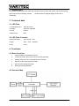
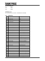
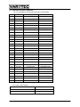
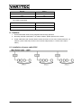
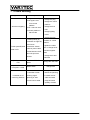
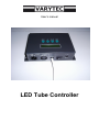
User’s manual
LED Tube Controller
Table of content
1. Safety instructions ........................................................................................................................... 3 2. Introduction ...................................................................................................................................... 4 3. Technical data ................................................................................................................................. 4 3.1. LED Tube................................................................................................................................. 4 3.2. LED Tube Controller ................................................................................................................ 4 4. Functions ......................................................................................................................................... 4 4.1. Basic Functions ....................................................................................................................... 4 4.2. Structure Map .......................................................................................................................... 4 4.3. Data DMX Wire ........................................................................................................................ 5 4.4. Button use................................................................................................................................ 5 4.4.1.
Mode Key......................................................................................................................... 5
4.4.2.
Setup key ......................................................................................................................... 6
4.4.3.
UP: ................................................................................................................................... 6
4.4.4.
DOWN ............................................................................................................................. 6
4.4.5.................................................................................................................................................. 6
4.4.6.
AUTO SELECT: ............................................................................................................... 6
5. Wire Linking Map.............................................................................................................................. 6 5.1. Functions of the Controller ...................................................................................................... 7 6. Caution ............................................................................................................................................. 8 6.1. Installation of power cable 230V.............................................................................................. 8 7. Trouble shooting............................................................................................................................... 9 2 / 10
1. Safety instructions
FOR SAFE AND EFFICIENT OPERATION
Be careful with heat and extreme temperatureAvoid exposing it
to direct rays of the sun or near a heating appliance.
Not put it in a temperature bellow 41°F /5°C, or exceeding 95°F /35°C.
Keep away from humidity, water and dust
Do not place the set in a location with high humidity or lots of dust.
Containers with water should not be placed on the set.
Keep away from sources of hum and noise
Such as transformer motor, tuner, TV set and amplifier.
To avoid placing on un-stable location
Select a level and stable location to avoid vibration.
Do not use chemicals or volatile liquids for cleaning
Use a clean dry cloth to wipe off the dust, or a wet soft cloth for stubborn dirt.
If out of work, contact sales agency immediately
Any troubles arose, remove the power plug soon, and contact with an engineer for repairing,
do not open the cabinet by yourself, it might result a
danger of electric shock.
Take care with the power cable
Never pull the power cable to remove the plug from the receptacle, be sure
to hold the plug. When not using the player for an extended period of time
be sure to disconnect the plug from the receptacle.
3 / 10
2. Introduction
This system consists LED color tube and controller,used for indoor and outdoor full color decorating
light project,such as buildings, bridges,
square,showroom,stage,shopping center,club or
advertising.
3. Technical data
3.1. LED Tube
1.Outline Dimension:
1000×50×75mm
2.Voltage:
90V/250V, 50/60HZ
3.Power:
P≤12W
4.Water Proof:
IP65
3.2. LED Tube Controller
Outline Dimension:
190×120×50(mm)
Votage:
100V-240V,50/60HZ
Power:
P≤1W
4. Functions
4.1. Basic Functions
1.
Support DMX512 long distance control.
2.
31 kinds of modes, each mode can be set with parameter.
3.
4000pcs LED tube can be operated by one controller.
4.
Edit auto mode,select appointed mode.
5.
Auto store the setting parameter.
6.
Re-set the preset parameter.
4.2. Structure Map
4 / 10
4.3. Data DMX Wire
Pin 1
GND
Pin 2
DMX –
Pin 3
DMX +
4.4. Button use
The 4 function keys on controller ---MODE,SETUP,UP,DOWN
4.4.1.
Mode Key
No.
Display
Discription
1
BLACK
Black
2
STATIC RED
Red
3
STATIC GREEN
Green
4
STATIC BLUE
Blue
5
STATIC YELLOW
Yellow
6
STATIC PURPLE
Purple
7
STATIC CYAN
Cyan
8
STATIC WHITE
White
9
COLOR CHANGE
Changing with 7 colors
10
FLOW CHASE
Slow flow chase
11
COLOR CHASE
More color chase
12
CORUSCAEE RUN
Flicker moving
13
FAST FLOW1
Fast flow chase 1
14
FAST FLOW2
Fast flow chase 2
15
ROLL CHASE
Rolling chase
16
ROLL COLOR
Rolling color
17
MULCOLOR1
Multi color changing 1
18
MULCOLOR2
Multi color changing 2
19
MULCOLOR3
Multi color changing 3
20
STROBE FLOW
Burst flow
21
R & G FLOW
Red & green flow
22
G & B FLOW
Green & blue flow
23
R & B FLOW
Red & blue flow
24
R & G CHASE
Red & green chase
25
R & B CHASE
Red & blue chase
26
Y & P CHASE
Yellow & purple chase
27
SMOOTH CHG1
Smooth slow change 1
28
SMOOTH CHG2
Smooth slow change 2
29
RAINBOW CHASE
Rainbow chase
30
AUTO PROGRAM
Auto run program
5 / 10
31
4.4.2.
DMX512 MODE
DMX512 mode
Setup key
No.
Display
1
Discription
Max
Min
INTERVAL
100
0
2
RUN SPEED
100
0
3
FLASH
100
0
4
LOAD DEFAULT
5
AUTO SELECT
6
TUBE QTY
4000
0
7
DMX512 ADDR
512
1
4.4.3.
YES / NO
UP:
Increase parameter/reset parameter (enter SETUP to confirm)
4.4.4.
DOWN
Decrease parameter/reset parameter (enter SETUP to confirm)
4.4.5.
Preset parameter: each kind with its own parameter stored in the controller. LOAD DEFAULT can
get back factory parameter. Under AUTO PROGRAM mode,use LOAD DEFAULT can renew all
kinds of parameter by factory.
4.4.6.
AUTO SELECT:
Run the selected kinds under AUTO PROGRAN mode.
5. Wire Linking Map
NOTE:
In DMX512 MODE, total 4 route signals can be received. The initiating ADD adjusted by UP,
DOWN(1-512), Preset initating ADD is 1. Each controller occupies 4 DMX512 ADD.
6 / 10
5.1. Functions of the Controller
No.1 Route DMX512 (0-255)control 29 kinds as below table:
No
Numeral
Display
Discription
1
0 8
BLACK
Black
2
0 17
STATIC RED
Red
3
18 26
STATIC GREEN
Green
4
27 35
STATIC BLUE
Blue
5
36 42
STATIC YELLOW
Yellow
6
43 51
STATIC PURPLE
Purple
7
52 60
STATIC CYAN
Cyan
8
61 69
STATIC WHITE
White
9
70 78
COLOR CHANGE
7 color change
10
79 87
FLOW CHASE
Slow flow chase
11
88 96
COLOR CHASE
Color chase
12
97 105
CORUSCAEE RUN
Flicker Run
13
106 114
FAST FLOW1
Fast Flow Chase1
14
115 123
FAST FLOW2
Fast Flow Chase2
15
124 132
ROLL CHASE
Roll Chase
16
133 141
ROLL COLOR
Roll Color
17
142 150
MULCOLOR1
Multi Color Shift1
18
151 159
MULCOLOR2
Multi Color Shift2
19
160 168
MULCOLOR3
Multi Color Shift3
20
169 177
STROBE FLOW
Strobe Flow
21
178 186
R & G FLOW
Red & Green Flow
22
187 195
G & B FLOW
Green & Blue Flow
23
196 204
R & B FLOW
Red & Blue Flow
24
205 213
R & G CHASE
Red & Green Chase
25
214 222
R & B CHASE
Red & Blue Chase
26
223 231
Y & P CHASE
Yellow PurpleChase
27
232 240
SMOOTH CHG1
Smooth change 1
28
241 249
SMOOTH CHG2
Smooth change 2
29
250 255
RAINBOW CHASE
Rainbow Chase
No.2 route control speed
Number
Speed
0
0
255
100
7 / 10
No.3 route control speed
Number
Speed
0
0
255
100
No.4 route control flash
Number
Speed
0
0
255
100
6. Caution
1. Unit avoid thunder areas, strong magnetic field and high pressure.
2. Normally controller used indoor, if in need of outdoor, please prevent rain or water.
3. Power cable rated 10A, if power load in series connection is over 10A, it needs extra jack ( in
220VAC, power cable only can link not more than 200pcs tubes, in 110VAC,max 100pcs
tubes )
6.1. Installation of power cable 230V
8 / 10
7. Trouble shooting
Appearance
Analysis
1 Plug no electricity
2 No signal come
from control
All tube not lighting
platform
3 No 1 tube not work
4 Control platform in
black mode
1 tubes quantity by
controller not right set
2 the loose
Former parts lit,back
connection of data
parts not lit
cable or power cable
3 tube between the lit
and unlit joint has
trouble
only mid part tubes
unlit
one part unlit or color
not equal in 1 tube
board trouble in that
place
Method
1 change the plug
2 change the control
platform
3 change the first
tube
4 change lighting
mode
1 change the tube
numbers on control
platform
2 tighten the cable
joint or change the lit
and unlit neighbor
tubes
3 change the lit and
unlit tubes
change the unlit tube
tube trouble
change tube
1 change controller
not stable,out of
control by platform
1 controller trouble
2 reduce the jamming
2 strong signal
3 increase load of
jamming in area
cable and extra
3 over load of cable
plugs,decrease
quantity of tubes
9 / 10
Importeur:
B & K Braun GmbH
Industriestraße 1
D-76307 Karlsbad
www.bkbraun.com
[email protected]
10 / 10