1
High Speed Data
Logger Module
User's Manual
(Hardware)
QD81DL96
Thank you for purchasing the Mitsubishi programmable controller
MELSEC-Q Series.
Prior to use, please read both this manual and detailed manual
thoroughly to fully understand the product.
Model
QD81DL96-U-HW
MODEL
13JY97
CODE
IB(NA)-0800441-C(1006)KWIX
© 2009 MITSUBISHI ELECTRIC CORPORATION
SAFETY PRECAUTIONS
(Always read these precautions before using this equipment.)
Before using this product, please read this manual and the relevant manuals
introduced in this manual carefully and pay full attention to safety to handle the
product correctly.
Note that these precautions apply only to this product.
For the safety precautions of the programmable controller system, please read the
User's Manual for the CPU module used.
In this manual, the safety instructions are ranked as "
WARNING" and
"
CAUTION".
WARNING
Indicates that incorrect handling may cause
hazardous conditions, resulting in death or severe
injury.
CAUTION
Indicates that incorrect handling may cause
hazardous conditions, resulting in minor or moderate
injury or property damage.
Note that the
CAUTION level may lead to a serious consequence according to
the circumstances.
Always follow the instructions of both levels because they are important to
personal safety.
Please save this manual to make it accessible when required and always forward
it to the end user.
A-1
[Design Precautions]
WARNING
Configure safety circuits external to the programmable controller to ensure
that the entire system operates safely even when a fault occurs in the
external power supply or the programmable controller. Failure to do so may
result in an accident due to an incorrect output or malfunction.
For the operating status of each station after a communication failure, refer
to relevant manuals for the network. Erroneous outputs and malfunctions
may lead to accidents.
Not doing so can cause an accident due to false output or malfunction.
To maintain the safety of the programmable controller system against
unauthorized access from external devices via the network, take appropriate
measures.
When changing data of the running programmable controller from a
peripheral connected to the CPU module or from a personal computer
connected to an intelligent function module or special function module,
configure an interlock circuit in the sequence program to ensure that the
entire system will always operate safely. For program modification and
operating status change, read relevant manuals carefully and ensure the
safety before operation.
Especially in the above mentioned control operations that are performed from
an external device to a remote programmable controller, any problems on the
programmable controller side may not be dealt with promptly due to
abnormal data communication. To prevent this, configure an interlock circuit
in the sequence program, and determine corrective actions to be taken
between the external device and CPU module in case of a communication
failure.
Do not write any data in the "system area" of the buffer memory in the
intelligent function module.
Also, do not use any "use prohibited" signals as an output signal from the
programmable controller CPU to the intelligent function module.
Doing so may cause malfunction of the programmable controller system.
A-2
[Design Precautions]
CAUTION
Do not bundle the control wires and the communication cables with the main
circuit and the power wires, and do not install them close to each other. They
should be installed at least 100 mm (3.94 in.) away from each other. Failure
to do so may generate noise that may cause malfunctions.
During registering each setting, do not power OFF the mounted module or
reset the programmable controller CPU.
Otherwise, data in the CompactFlashTM card will be undefined. Therefore,
resetting and re-registering data are required.
This may also cause a module failure or malfunctions.
A-3
[Installation Precautions]
CAUTION
Use the programmable controller in an environment that meets the general
specifications in the user’s manual for the CPU module used. Using the
programmable controller in any other operating environments may cause
electric shocks, fires or malfunctions, or may damage or degrade the module.
While pressing the installation lever located at the bottom of module, insert
the module fixing tab into the fixing hole in the base unit until it stops. Then,
securely mount the module with the fixing hole as a supporting point.
If the module is not installed properly, it may cause the module to
malfunction, fail or fall off.
Secure the module with screws especially when it is used in an environment
where constant vibrations may occur.
Be sure to tighten the screws using the specified torque. If the screws loose,
it may cause the module to short-circuit, malfunction or fall off. If the screws
are tightened excessively, it may damage the screws and cause the module
to short-circuit, malfunction or fall off.
Before mounting/dismounting the module, be sure to shut off all phases of
external power supply used by the system.
Failure to do so may cause product damage.
Do not directly touch any conductive part or electronic component of the
module.
This may cause the module to malfunction or fail.
Push the CompactFlashTM card into the CompactFlashTM card slot and install it
securely.
After installing the CompactFlashTM card, check that it is inserted securely.
Failure to do so may cause malfunctions due to poor contact.
A-4
[Wiring Precautions]
CAUTION
Connectors for external connection must be crimped or pressed with the tool
specified by the manufacturer, or must be correctly soldered.
If the connection is incomplete, it may cause the module to short circuit,
catch fire, or malfunction.
Install connectors securely to modules.
Make sure to place the communication and power cables to be connected to
the module in a duct or fasten them using a clamp. If the cables are not
placed in a duct or fastened with a clamp, their positions may be unstable or
moved, and they may be pulled inadvertently.
This may damage the module and the cables or cause the module to
malfunction because of faulty cable connections.
When disconnecting the communication and power cables from the module,
do not pull the cables by hand. When disconnecting a cable with a connector,
hold the connector to the module by hand and pull it out to remove the cable.
When disconnecting a cable connected to a terminal block, loosen the
screws on the terminal block first before removing the cable. If a cable is
pulled while being connected to the module, it may cause the module to
malfunction or damage the module and the cable.
Be careful not to let any foreign matter such as wire chips get inside the
module. They may cause fire, as well as breakdowns and malfunctions of the
module.
A protective sheet is pasted on the upper part of the module in order to
prevent foreign matter such as wire chips to get inside the module while
wiring.
Do not remove this protective sheet during wiring work. However, be sure to
remove the protective sheet before operating the module to allow heat
radiation during operation.
A-5
[Disposal Precautions]
CAUTION
Dispose of this product as an industrial waste.
A-6
CONDITIONS OF USE FOR THE PRODUCT
(1) Mitsubishi programmable controller ("the PRODUCT") shall be used in
conditions;
i) where any problem, fault or failure occurring in the PRODUCT, if any,
shall not lead to any major or serious accident; and
ii) where the backup and fail-safe function are systematically or
automatically provided outside of the PRODUCT for the case of any
problem, fault or failure occurring in the PRODUCT.
(2) The PRODUCT has been designed and manufactured for the purpose of
being used in general industries.
MITSUBISHI SHALL HAVE NO RESPONSIBILITY OR LIABILITY
(INCLUDING, BUT NOT LIMITED TO ANY AND ALL RESPONSIBILITY
OR LIABILITY BASED ON CONTRACT, WARRANTY, TORT, PRODUCT
LIABILITY) FOR ANY INJURY OR DEATH TO PERSONS OR LOSS OR
DAMAGE TO PROPERTY CAUSED BY the PRODUCT THAT ARE
OPERATED OR USED IN APPLICATION NOT INTENDED OR
EXCLUDED BY INSTRUCTIONS, PRECAUTIONS, OR WARNING
CONTAINED IN MITSUBISHI'S USER, INSTRUCTION AND/OR
SAFETY MANUALS, TECHNICAL BULLETINS AND GUIDELINES FOR
the PRODUCT.
("Prohibited Application")
Prohibited Applications include, but not limited to, the use of the
PRODUCT in;
• Nuclear Power Plants and any other power plants operated by Power
companies, and/or any other cases in which the public could be
affected if any problem or fault occurs in the PRODUCT.
• Railway companies or Public service purposes, and/or any other cases
in which establishment of a special quality assurance system is
required by the Purchaser or End User.
• Aircraft or Aerospace, Medical applications, Train equipment, transport
equipment such as Elevator and Escalator, Incineration and Fuel
devices, Vehicles, Manned transportation, Equipment for Recreation
and Amusement, and Safety devices, handling of Nuclear or
Hazardous Materials or Chemicals, Mining and Drilling, and/or other
applications where there is a significant risk of injury to the public or
property.
A-7
Notwithstanding the above, restrictions Mitsubishi may in its sole
discretion, authorize use of the PRODUCT in one or more of the
Prohibited Applications, provided that the usage of the PRODUCT is
limited only for the specific applications agreed to by Mitsubishi and
provided further that no special quality assurance or fail-safe, redundant
or other safety features which exceed the general specifications of the
PRODUCTs are required. For details, please contact the Mitsubishi
representative in your region.
A-8
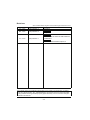
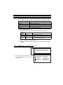
Revisions
* The manual number is given on the bottom right of the front cover.
Print date
Jan., 2009
* Manual number
IB(NA)-0800441-A
Mar., 2009
IB(NA)-0800441-B
Jun., 2010
IB(NA)-0800441-C
Revision
First edition
Correction
Chapter3,7
Addition
CONDITIONS OF USE FOR THE PRODUCT,
WARRANTY
Correction
SAFETY PRECAUTIONS,Chapter3,6
This manual confers no industrial property rights or any rights of any other kind, nor does it
confer any patent licenses. Also, Mitsubishi Electric Corporation cannot be held responsible
for any problems involving industrial property rights which may occur as a result of using the
contents in this manual.
© 2009 MITSUBISHI ELECTRIC CORPORATION
A-9
CONTENTS
1. OVERVIEW..................................................................................................... 1
2. PERFORAMNCE SPECIFICATIONS ............................................................. 2
3. PART NAMES................................................................................................. 3
4. LOADING AND INSTALLATION..................................................................... 5
4.1 Handling Precautions ............................................................................... 5
4.2 Installation Environment ........................................................................... 5
5. EXTERNAL WIRING....................................................................................... 6
5.1 Connecting to the 10BASE-T/100BASE-TX ............................................. 6
6. SETTING FROM GX DEVELOPER................................................................ 7
7. EXTERNAL DIMENSIONS ............................................................................. 9
A-10
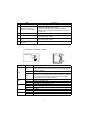
About Manual
The following manual is also related to this product.
In necessary, order it by quoting the details in the table below.
Related Manual
Manual name
High Speed Data Logger Module User's Manual
Manual No.
(Model code)
SH-080818ENG
(13JZ30)
Compliance with the EMC and Low Voltage Directives
(1) For programmable controller system
To configure a system meeting the requirements of the EMC and
Low Voltage Directives when incorporating the Mitsubishi
programmable controller (EMC and Low Voltage Directives
compliant) into other machinery or equipment, refer to Chapter 9
"EMC AND LOW VOLTAGE DIRECTIVES" of the QCPU User's
Manual (Hardware Design, Maintenance and Inspection).
The CE mark, indicating compliance with the EMC and Low Voltage
Directives, is printed on the rating plate of the programmable
controller.
(2) For the product
For the compliance of this product with the EMC and Low Voltage
Directives, refer to Section 9.1.3 "Cables" in Chapter 9 "EMC AND
LOW VOLTAGE DIRECTIVES" of the QCPU User's Manual
(Hardware Design, Maintenance and Inspection).
A-11
1. OVERVIEW
This manual explains how to install the QD81DL96 high speed data
logger module (hereafter, abbreviated as high speed data logger
module) and how to wire them with other devices.
(Packing list)
Model
QD81DL96
Product name
QD81DL96 High speed data logger module *1
Quantity
1
*1 : A battery is not required for the high speed data logger module.
1
2. PERFORAMNCE SPECIFICATIONS
The following describes the performance specifications of the high
speed data logger module.
For general specifications of the high speed data logger module, refer to
the following manual.
QCPU User's Manual (Hardware Design, Maintenance and
Inspection)
Item
Interface*1
Data
transmission rate
Transmission
method
Ethernet
No. of cascaded
stages
Max. segment
length*2
Supported
function
Supply power
voltage
Supply power
CompactFlashTM capacity
card
Card size
No. of
installable cards
Number of occupied I/O points
Clock
5VDC internal current consumption
External dimensions
Weight
10BASE-T
Specifications
100BASE-TX
10 Mbps
100 Mbps
Base band
Maximum 4 stages
Maximum 2 stages
100 m
The auto-negotiation function is available. (automatically
distinguishes 10BASE-T from 100BASE-TX)
3.3V
5%
Maximum 150 mA
TYPE I card
1
32 points/slot (I/O assignment: Intelli. 32 points)
The clock data are obtained from a programmable
controller CPU (in multiple CPU system, CPU No.1) or
the SNTP server computer.
The clock accuracy after the clock data are obtained:
Daily error 9.504 seconds*3
0.46A
98 (3.86) (H) 27.4 (1.08) (W) 90(3.54) (D) [mm
(inch)]
0.15kg
*1 : The high speed data logger module distinguishes 10BASE-T from 100BASETX depending on the device on other end.
For connection with a hub not having the auto-negotiation function, set the
hub side to half-duplex auto communication mode.
*2 : Distance between a hub and node.
*3 : The clock data are reobtained every 24 hours for a programmable controller
CPU, and per user specified cycle for the SNTP server.
2
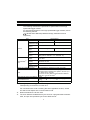
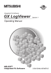
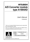
3. PART NAMES
(1) With the LED cover closed
QD81DL96
RUN
ERR.
CF
1)
PULL
CF CARD
10BASE-T/
100BASE-TX
100
M
1)
SD/
RD
1)
2)
QD81DL96
3)
(2) With the LED cover open
4)
PULL
CF CARD
5)
10BASE-T/
100BASE-TX
6)
100
M
SD/
RD
QD81DL96
*1 : A battery is not required for the high speed data logger module.
3
Name
Indicator LED
1)
2)
10BASE-T/100BASE-TX
interface connector (RJ45)
3)
Serial number plate
4)
EJECT button
CompactFlashTM card
slot
CompactFlashTM card
slot cover
5)
6)
Description
Refer to (3) Indicator LED display contents.
Used for connecting the high speed data logger module in
10BASE-T/100BASE-TX connection.
(The high speed data logger module distinguishes
10BASE-T from 100BASE-TX depending on the device
on other end.)
Indicate the serial No. of the QD81DL96.
Used for ejecting a CompactFlashTM card from the high
speed data logger module.
Used for installing a CompactFlashTM card to the high
speed data logger module.
Cover for the CompactFlashTM card slot
*1 : A battery is not required for the high speed data logger module.
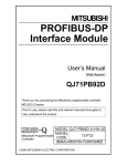
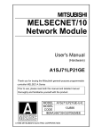
(3) Indicator LED display contents
QD81DL96
100
M
RUN
ERR.
CF
SD/
RD
Name
LED status
ON
RUN
OFF
Flash
ERR.
CF
100 M
SD/RD
OFF
ON
Flash
ON
OFF
Flash
ON
OFF
ON
OFF
Description
In normal operation
(It may take some time until the RUN LED is turned ON after the
module is started.)
Watchdog timer error (Hardware error)
Module check
(Flashes for 10 seconds when the module check button is clicked
on the high speed data logger module search screen of the
Configuration Tool or the GX LogViewer.)
In normal status
Module continuation error
Module stop error
Accessible to CompactFlashTM card
Not accessible to CompactFlashTM card (Removable status)
CompactFlashTM card in preparation
100 Mbps
10 Mbps
During data send or data receive
Data not transmitted
4
4. LOADING AND INSTALLATION
4.1 Handling Precautions
(1) Do not drop or apply severe shock to the module.
(2) Before touching the module, always touch grounded metal, etc. to
discharge static electricity from human body, etc.
Not doing so can cause the module to fail or malfunction.
(3) Tighten the module fixing screws within the following range.
Screw
Module fixing screw(M3 screw)*1
Tightening torque range
0.36 to 0.48 N•m
*1 : The module can be easily fixed onto the base unit using the
hook at the top of the module.
However, it is recommended to secure the module with the
module fixing screw if the module is subject to significant
vibration.
4.2 Installation Environment
For details, refer to the user's manual for the CPU module used.
5
5. EXTERNAL WIRING
5.1 Connecting to the 10BASE-T/100BASE-TX
When connecting to the 10BASE-T/100BASE-TX interface, use twisted
pair cable.
Use twisted pair cable that meets IEEE802.3 10BASE-T/100BASE-TX
standards.
(1) For 100 Mbps
Either (a) or (b) of the following can be used.
(a) Unshielded twisted pair cable (UTP cable), Category 5 or later
(b) Shielded twisted pair cable (STP cable), Category 5 or later
(2) For 10 Mbps
Either (a) or (b) of the following can be used.
(a) Unshielded twisted pair cable (UTP cable), Category 3 or later
(b) Shielded twisted pair cable (STP cable), Category 3 or later
POINT
During high speed communication (100 Mbps) via 100BASE-TX connection,
communication errors may occur due to the effect of high frequency noise
generated from the equipment other than programmable controller, depending
on the installation environment.
Take the following countermeasures on the high speed data logger module
side to eliminate the effect of high frequency noise when constructing the
network system.
(1) Wiring
• Do not install the twisted pair cables together with the main circuit or
power lines, or bring them close to each other.
• Make sure to place the twisted pair cable in a duct.
(2) Cable
• In the environment where the cable is susceptible to noise, use the
shielded twisted pair cable (STP cable).
(3) 10 Mbps communication
• Connect the 10 Mbps-compatible equipment with the high speed
data logger module and transmit the data to the equipment at a
transmission speed of 10 Mbps.
6
6. SETTING FROM GX DEVELOPER
The intelligent function module switches are used to make the mode
setting, default operation setting, and response monitoring time setting.
Switch number
Switch 1
Switch 2
Switch 3 (Lower byte)
Switch 4
Switch 5
Description
Mode setting
Default operation setting
Response monitoring time setting
Compatibility setting
For system use (Do not set.)
(1) Mode setting (Switch 1)
Select the high speed data logger module operation mode.
Setting
number
0000H
0001H
0002H
Item
Description
Online
Hardware test
Self-loopback
test
Normal operation mode
Tests the ROM/RAM switch settings.
Executes the 10BASE-T/100BASE-TX
interface self-diagnostics test.
(2) Default operation setting (Switch 2)
Select the default operation setting for the high speed data logger
module.
b15
to
Specify "0".*1
b3 b2 b1 b0
Switch 2
Default operation setting [Account setting]
0: Operates according to [Account setting].
1: Operates according to the default.
The access authentication function is not
used.
*1 : When other than 0 is specified in this
area, "Switch setting error" (0180H) occurs
at hardware test.
7
Default operation setting [Network settings]
0: Operates according to [Network settings].
1: Operates according to the default.
IP ADDRESS
: 192.168.3.3
Subnet mask
: 255.255.255.0
Host name
: QD81DL96
Does not perform network diagnostics
(ping).
(3) Response monitoring time setting (Switch 3 (Lower byte))
Set the timeout time (Second) from when the high speed data
logger module sends a request to the access target CPU until
receiving the reply.
A response time-out error (0002H) occurs if the access target CPU
does not respond within the set time.
Setting range: 15 to 255 (Second) (Default value: 15 seconds)
When setting the time between 0 and 14 or making no settings,
response monitoring time operates with 15 seconds.
b15
to
(Upper byte)*1
b8b7
b0
to
(Lower byte)
Switch 3
Specify "0".
*1 : The upper byte data are ignored. However,
when other than 0 is specified in this area,
"Switch setting error" (0180H) occurs at
hardware test
Response monitoring time setting
15 to 255 (Second)
When setting the time between
0 and 14 or making no settings,
response monitoring time operates
with 15 seconds.
(4) Compatibility setting (Switch 4)
Set this switch to make the process, which may differ depending on
a function version (the first five digits of the serial number), the
same as that on another function version (the first five digits of the
serial number).
b15
to
Specify 0.*
b3 b2 b1 b0
Compatibility setting (File switching timing)
* If this area is a value other than 0,
it will cause a switch setting error (0180H)
during hardware testing.
0: The module operates as the module of which the first five
digits of the serial number are "11102" or later.
1: The module operates as the module of which the first five
digits of the serial number are "11101" or lower.
8
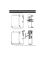
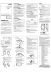
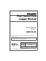
7. EXTERNAL DIMENSIONS
QD81DL96
RUN
ERR.
CF
PULL
CF CARD
98 (3.86)
10BASE-T/
100BASE-TX
100
M
SD/
RD
*1
R1
4
(0.16)
QD81DL96
27.4
(1.08)
(0.55)
14
90 (3.54)
PULL
CF CARD
10BASE-T/
100BASE-TX
100
M
SD/
RD
QD81DL96
(Unit: mm (inch))
*1 : The bending radius near the connector (R1: yardstick) should be at least four
times longer than the cable's outside diameter when the twisted pair cable is
connected.
CompactFlash is a trademark of SanDisk Corporation in the United States
and other countries.
All other company names and product names used in this manual are
trademarks or registered trademarks of their respective companies.
9
Warranty
Please confirm the following product warranty details before using this product.
1. Gratis Warranty Term and Gratis Warranty Range
If any faults or defects (hereinafter "Failure") found to be the responsibility of
Mitsubishi occurs during use of the product within the gratis warranty term,
the product shall be repaired at no cost via the sales representative or
Mitsubishi Service Company.
However, if repairs are required onsite at domestic or overseas location,
expenses to send an engineer will be solely at the customer's discretion.
Mitsubishi shall not be held responsible for any re-commissioning,
maintenance, or testing on-site that involves replacement of the failed
module.
[Gratis Warranty Term]
The gratis warranty term of the product shall be for one year after the date of
purchase or delivery to a designated place.
Note that after manufacture and shipment from Mitsubishi, the maximum
distribution period shall be six (6) months, and the longest gratis warranty
term after manufacturing shall be eighteen (18) months. The gratis warranty
term of repair parts shall not exceed the gratis warranty term before repairs.
[Gratis Warranty Range]
(1) The range shall be limited to normal use within the usage state, usage
methods and usage environment, etc., which follow the conditions and
precautions, etc., given in the instruction manual, user's manual and
caution labels on the product.
(2)Even within the gratis warranty term, repairs shall be charged for in the
following cases.
1. Failure occurring from inappropriate storage or handling, carelessness
or negligence by the user. Failure caused by the user's hardware or
software design.
2. Failure caused by unapproved modifications, etc., to the product by
the user.
3. When the Mitsubishi product is assembled into a user's device, Failure
that could have been avoided if functions or structures, judged as
necessary in the legal safety measures the user's device is subject to
or as necessary by industry standards, had been provided.
4. Failure that could have been avoided if consumable parts (battery,
backlight, fuse, etc.) designated in the instruction manual had been
correctly serviced or replaced.
5. Failure caused by external irresistible forces such as fires or abnormal
voltages, and Failure caused by force majeure such as earthquakes,
lightning, wind and water damage.
6. Failure caused by reasons unpredictable by scientific technology
standards at time of shipment from Mitsubishi.
7. Any other failure found not to be the responsibility of Mitsubishi or that
admitted not to be so by the user.
10
2. Onerous repair term after discontinuation of production
(1) Mitsubishi shall accept onerous product repairs for seven (7) years after
production of the product is discontinued.
Discontinuation of production shall be notified with Mitsubishi Technical
Bulletins, etc.
(2) Product supply (including repair parts) is not available after production is
discontinued.
3. Overseas service
Overseas, repairs shall be accepted by Mitsubishi's local overseas FA
Center. Note that the repair conditions at each FA Center may differ.
4. Exclusion of loss in opportunity and secondary loss from warranty
liability
Regardless of the gratis warranty term, Mitsubishi shall not be liable for
compensation of damages caused by any cause found not to be the
responsibility of Mitsubishi, loss in opportunity, lost profits incurred to the
user by Failures of Mitsubishi products, special damages and secondary
damages whether foreseeable or not , compensation for accidents, and
compensation for damages to products other than Mitsubishi products,
replacement by the user, maintenance of on-site equipment, start-up test run
and other tasks.
5. Changes in product specifications
The specifications given in the catalogs, manuals or technical documents
are subject to change without prior notice.
11
Country/Region Sales office/Tel
Country/Region Sales office/Tel
U.S.A
Mitsubishi Electric Automation Inc.
500 Corporate Woods Parkway Vernon
Hills, IL 60061, U.S.A.
Tel : +1-847-478-2100
Hong Kong Mitsubishi Electric Automation
(Hong Kong) Ltd.
10th Floor, Manulife Tower, 169 Electric
Road, North Point, Hong Kong
Tel : +852-2887-8870
Brazil
MELCO-TEC Rep. Com.e Assessoria
Tecnica Ltda.
Rua Correia Dias, 184,
Edificio Paraiso Trade Center-8 andar
Paraiso, Sao Paulo, SP Brazil
Tel : +55-11-5908-8331
Germany
Mitsubishi Electric Europe B.V. German
Branch
Gothaer Strasse 8 D-40880 Ratingen,
GERMANY
Tel : +49-2102-486-0
U.K
Mitsubishi Electric Europe B.V. UK
Branch
Travellers Lane, Hatfield, Hertfordshire.,
AL10 8XB, U.K.
Tel : +44-1707-276100
Italy
Mitsubishi Electric Europe B.V. Italian
Branch
Centro Dir. Colleoni, Pal. Perseo-Ingr.2
Via Paracelso 12, I-20041 Agrate Brianza.,
Milano, Italy
Tel : +39-039-60531
Spain
France
Mitsubishi Electric Europe B.V. Spanish
Branch
Carretera de Rubi 76-80,
E-08190 Sant Cugat del Valles,
Barcelona, Spain
Tel : +34-93-565-3131
Mitsubishi Electric Europe B.V. French
Branch
25, Boulevard des Bouvets, F-92741
Nanterre Cedex, France
TEL: +33-1-5568-5568
South Africa Circuit Breaker Industries Ltd.
Private Bag 2016, ZA-1600 Isando,
South Africa
Tel : +27-11-928-2000
China
Mitsubishi Electric Automation
(China) Ltd.
4/F Zhi Fu Plazz, No.80 Xin Chang Road,
Shanghai 200003, China
Tel : +86-21-6120-0808
Taiwan
Setsuyo Enterprise Co., Ltd.
6F No.105 Wu-Kung 3rd.Rd, Wu-Ku
Hsiang, Taipei Hsine, Taiwan
Tel : +886-2-2299-2499
Korea
Mitsubishi Electric Automation Korea Co., Ltd.
1480-6, Gayang-dong, Gangseo-ku
Seoul 157-200, Korea
Tel : +82-2-3660-9552
Singapore
Mitsubishi Electric Asia Pte, Ltd.
307 Alexandra Road #05-01/02, Mitsubishi
Electric Building, Singapore 159943
Tel : +65-6470-2460
Thailand
Mitsubishi Electric Automation (Thailand)
Co., Ltd.
Bang-Chan Industrial Estate No.111
Moo 4, Serithai Rd, T.Kannayao,
A.Kannayao, Bangkok 10230 Thailand
Tel : +66-2-517-1326
Indonesia
P.T. Autoteknindo Sumber Makmur
Muara Karang Selatan, Block A/Utara
No.1 Kav. No.11 Kawasan Industri
Pergudangan Jakarta - Utara 14440,
P.O.Box 5045 Jakarta, 11050 Indonesia
Tel : +62-21-6630833
India
Messung Systems Pvt, Ltd.
Electronic Sadan NO:III Unit No15,
M.I.D.C Bhosari, Pune-411026, India
Tel : +91-20-2712-3130
Australia
Mitsubishi Electric Australia Pty. Ltd.
348 Victoria Road, Rydalmere,
N.S.W 2116, Australia
Tel : +61-2-9684-7777
HEAD OFFICE : TOKYO BUILDING, 2-7-3 MARUNOUCHI, CHIYODA-KU, TOKYO 100-8310, JAPAN
NAGOYA WORKS : 1-14, YADA-MINAMI 5-CHOME, HIGASHI-KU, NAGOYA, JAPAN
When exported from Japan, this manual does not require application to the Ministry
of Economy, Trade and Industry for service transaction permission.
Specifications subject to change without notice.
Printed in Japan on recycled paper.