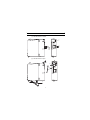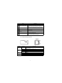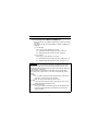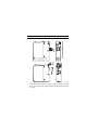
1
MES Interface Module
User's Manual
(Hardware)
QJ71MES96
Thank you for purchasing the Mitsubishi programmable controller
MELSEC-Q Series.
Prior to use, please read both this manual and detailed manual
thoroughly to fully understand the product.
Model QJ71MES96-U-HW
MODEL
13JY02
CODE
IB(NA)-0800354-C(0809)MEE
© 2006 MITSUBISHI ELECTRIC CORPORATION
SAFETY PRECAUTIONS
(Always read these precautions before using this equipment.)
Before using this product, please read this manual and the relevant manuals
introduced in this manual carefully and pay full attention to safety to handle the
product correctly.
Note that these precautions apply only to this product.
For the safety precautions of the programmable controller system, please read the
User's Manual for the CPU module used.
In this manual, the safety instructions are ranked as "DANGER" and "CAUTION".
DANGER
Indicates that incorrect handling may cause
hazardous conditions, resulting in death or severe
injury.
CAUTION
Indicates that incorrect handling may cause
hazardous conditions, resulting in medium or slight
personal injury or physical damage.
Note that the
CAUTION level may lead to a serious consequence according to
the circumstances.
Always follow the instructions of both levels because they are important to
personal safety.
Please save this manual to make it accessible when required and always forward
it to the end user.
A-1
[Design Precautions]
DANGER
When controlling a running programmable controller (e.g. data modification),
create an interlock circuit on sequence programs so that the whole system
functions safely all the time.
Also, be sure to read the manual carefully and ensure safety before
performing any other controls such as operating status change.
Especially, when controlling a programmable controller from a remote
location via network, problems on the programmable controller side may not
be dealt with promptly due to failure of data communications.
Create an interlock circuit on a sequence program.
For the operation status of each station at a communication error, refer to the
manual for that station.
Incorrect output or malfunctions may cause an accident.
Install a safety circuit external to the programmable controller that keeps the
entire system safe even when there are problems with the external power
supply or the programmable controller.
Otherwise, trouble could result from erroneous output or erroneous
operation.
When the programmable controller system security needs to be protected
against illegal access from an external device via a network, take measures
at the user's discretion.
Do not write any data to the "System area" in the buffer memory of the
intelligent function module.
As for signals output from the programmable controller CPU to the intelligent
function module, never output (ON) a "Use prohibited" signal.
Doing these operations may cause malfunctions of the programmable
controller system.
A-2
[Design Precautions]
CAUTION
Do not bunch the control wires or communication cables with the main circuit
or power wires, or install them close to each other.
They should be installed 100 mm (3.94 inch) or more from each other.
Not doing so could result in noise that would cause erroneous operation.
During registering each setting, do not power OFF the mounted module or
reset the programmable controller CPU.
Otherwise, data in the CompactFlash card will be undefined. Therefore,
resetting and re-registering data are required.
This may also cause a module failure or malfunctions.
[Installation Precautions]
CAUTION
Use the programmable controller under the environment specified in the
User's Manual.
Using this programmable controller in an environment outside the range of
the general specifications could result in electric shock, fire, erroneous
operation, and damage to or deterioration of the product.
While pressing the installation lever located at the bottom of module, insert
the module fixing tab into the fixing hole in the base unit until it stops. Then,
securely mount the module with the fixing hole as a supporting point.
Incorrect loading of the module can cause a malfunction, failure or drop.
When using the programmable controller in the environment of much
vibration, tighten the module with a screw.
A-3
[Installation Precautions]
CAUTION
Completely turn off the externally supplied power used in the system before
mounting or removing the module.
Not doing so could result in damage to the product.
Tighten the screw in the specified torque range.
Undertightening can cause a drop, short circuit or malfunction.
Overtightening can cause a drop, short circuit or malfunction due to damage
to the screw or module.
Do not directly touch the module's conductive parts or electronic
components.
Touching the conductive parts could cause an operation failure or give
damage to the module.
When connecting a connector, properly press, crimp, or solder it using the
tools specified by the manufacturer.
Incomplete connection may cause short-circuit, fire, and malfunctions.
Push the CompactFlash card into the CompactFlash card slot and install it
securely.
After installing the CompactFlash card, check that it is inserted securely.
Failure to do so may cause malfunctions due to poor contact.
[Wiring Precautions]
CAUTION
Always store the communication cables and power cables connected to the
module in the duct or fix them in place with clamps.
Not doing so may cause swing, move, or poor connection of the cable, or
damage of a module and/or cable due to careless pull, resulting in
malfunctions.
Install connectors securely to modules.
A-4
[Wiring Precautions]
CAUTION
Tighten the screw in the specified torque range.
Undertightening can cause a drop, short circuit or malfunction.
Overtightening can cause a drop, short circuit or malfunction due to damage
to the screw or module.
When disconnecting communication cables connected to the module, never
pull on the cable section.
When using a cable with a connector, disconnect it with holding the
connector connected to the module.
When the cable is pulled while connected to the module, this may cause
malfunctions or module/cable damage.
Be sure there are no foreign substances such as sawdust or wiring debris
inside the module.
Such debris could cause fires, damage, or erroneous operation.
The module has an ingress prevention label on its top to prevent foreign
matter, such as wire offcuts, from entering the module during wiring.
Do not peel this label during wiring.
Before starting system operation, be sure to peel this label because of heat
dissipation.
[Disposal Precautions]
CAUTION
When disposing of this product, treat it as industrial waste.
When disposing of batteries, separate them from other wastes according to
the local regulations. (For details of the battery directive in EU member
states, refer to the MES Interface Module User's Manual.)
[Transportation Precautions]
CAUTION
When transporting lithium batteries, make sure to treat them based on the
transportation regulations. (Refer to Chapter8 for details of the relevant
models.)
A-5
Revisions
* The manual number is given on the bottom right of the front cover.
Print date
Jul., 2006
Dec., 2007
* Manual number
IB(NA)-0800354-A
IB(NA)-0800354-B
Revision
First edition
Change of a term
"PLC" was changed to "programmable
controller".
Correction
SAFETY PRECAUTIONS, Chapter1,
Section3.1
Sep., 2008
IB(NA)-0800354-C
Correction
About Manual, Compliance with the EMC and
Low Voltage Directives, Section3.1
This manual confers no industrial property rights or any rights of any other kind, nor does it
confer any patent licenses. Also, Mitsubishi Electric Corporation cannot be held responsible
for any problems involving industrial property rights which may occur as a result of using the
contents in this manual.
© 2006 MITSUBISHI ELECTRIC CORPORATION
A-6
CONTENTS
1. OVERVIEW .................................................................................................... 1
2. PERFORAMNCE SPECIFICATIONS ............................................................. 2
3. LOADING AND INSTALLATION .................................................................... 3
3.1 Handling Precautions ............................................................................... 3
3.2 Installation Environment ........................................................................... 3
4. PART NAMES ................................................................................................ 4
5. EXTERNAL WIRING ...................................................................................... 6
5.1 Connecting to the 10BASE-T/100BASE-TX ............................................. 6
6. SETTING FROM GX DEVELOPER ............................................................... 7
7. EXTERNAL DIMENSIONS ............................................................................. 9
8. TRANSPORTATION PRECAUTIONS.......................................................... 10
8.1 Controlled Model .................................................................................... 10
8.2 Handling for Shipping ............................................................................. 10
A-7
About Manual
The following manual is also related to this product.
In necessary, order it by quoting the details in the table below.
Related Manual
Manual No.
(Model code)
SH-080644ENG
(13JR95)
Manual name
MES Interface Module User's Manual
Compliance with the EMC and Low Voltage Directives
(1) For programmable controller system
To configure a system meeting the requirements of the EMC and
Low Voltage Directives when incorporating the Mitsubishi
programmable controller (EMC and Low Voltage Directives
compliant) into other machinery or equipment, refer to Chapter 9
"EMC AND LOW VOLTAGE DIRECTIVES" of the QCPU User's
Manual (Hardware Design, Maintenance and Inspection).
The CE mark, indicating compliance with the EMC and Low Voltage
Directives, is printed on the rating plate of the programmable
controller.
(2) For the product
For the compliance of this product with the EMC and Low Voltage
Directives, refer to Section 9.1.3 "Cables" in Chapter 9 "EMC AND
LOW VOLTAGE DIRECTIVES" of the QCPU User's Manual
(Hardware Design, Maintenance and Inspection).
A-8
1. OVERVIEW
This manual explains how to install the QJ71MES96 MES interface
module (hereafter, abbreviated as MES interface module) and how to
wire them with other devices.
(Packing list)
Model
QJ71MES96
Product name
QJ71MES96 MES interface module
Battery (Q6BAT)
1
Quantity
1
1
2. PERFORAMNCE SPECIFICATIONS
The following describes the performance specifications of the MES
interface module.
For general specifications of the MES interface module, refer to the
following manual.
QCPU User's Manual (Hardware Design, Maintenance and
Inspection)
Item
Interface*1
Data
transmission
rate
Transmission
method
Ethernet
No. of
cascaded
stages
Max. segment
length*2
Supported
function
Supply power
voltage
Supply power
CompactFlash capacity
card
Card size
No. of
installable
cards
Number of occupied I/O points
Clock
5VDC internal current
consumption
External dimensions
Weight
*1
Specifications
100BASE-TX
10BASE-T
10 Mbps
100 Mbps
Base band
Maximum 4 stages
Maximum 2 stages
100 m
The auto-negotiation function is available. (automatically
distinguishes 10BASE-T from 100BASE-TX)
3.3V
5%
Maximum 150 mA
TYPE I card
1
32 points/slot (I/O assignment: Intelli. 32 points)
The clock data is obtained from a programmable controller
CPU (in multiple CPU system, CPU No.1) or the SNTP server
computer.
0.65A
98 (3.86) (H)
0.16kg
27.4 (1.08) (W)
90(3.54) (D) [mm (inch)]
The MES interface module distinguishes 10BASE-T from 100BASE-TX
depending on the device on other end.
For connection with a hub not having the auto-negotiation function, set the
hub side to half-duplex auto communication mode.
*2
Distance between a hub and node.
2
3. LOADING AND INSTALLATION
3.1 Handling Precautions
(1) Do not drop or apply severe shock to the module case since it is
made of resin.
(2) Before touching the module, always touch grounded metal, etc. to
discharge static electricity from human body, etc.
Not doing so can cause the module to fail or malfunction.
(3) Tighten the module fixing screws within the following range.
Screw
Module fixing screw (usually not
required)
(M3 screw)*1
*1
Tightening torque range
0.36 to 0.48 N•m
The module can be easily fixed onto the base unit using the hook at the top
of the module.
However, it is recommended to secure the module with the module fixing
screw if the module is subject to significant vibration.
3.2 Installation Environment
For details, refer to the user's manual for the CPU module used.
3
4. PART NAMES
(1) With the LED cover closed
QJ71MES96
RUN
ERR.
1)
PULL
CF CARD
10BASE-T/
100BASE-TX
1)
2)
100
M
SD/
RD
QJ71MES96
(2) With the LED cover open
3)
PULL
CF CARD
4)
5)
10BASE-T/
100BASE-TX
100
M
SD/
RD
QJ71MES96
6)
7)
4
Name
Indicator LED
1)
2)
10BASE-T/100BASE-TX
interface connector (RJ45)
3)
EJECT button
6)
CompactFlash card
slot
CompactFlash card
slot cover
Battery
7)
Battery connector pin
4)
5)
Description
Refer to (3) Indicator LED display contents.
Used for connecting the MES interface module in
10BASE-T/100BASE-TX connection.
(The MES interface module distinguishes 10BASE-T from
100BASE-TX depending on the device on other end.)
Used for ejecting a CompactFlash card from the MES
interface module.
Used for installing a CompactFlash card to the MES
interface module.
Cover for the CompactFlash card slot
Battery for file protection
Connector pin for battery lead
(The battery lead is disconnected from the connector at
shipment to prevent battery consumption.)
(3) Indicator LED display contents
10BASE-T/
100BASE-TX
QJ71MES96
100
M
RUN
ERR.
SD/
RD
Name
RUN
ERR.
100 M
SD/RD
LED status
ON
OFF
OFF
ON
Flash
ON
OFF
ON
OFF
Description
In normal operation
(It may take some time until the RUN LED is turned ON after the
module is started.)
Watchdog timer error (Hardware error)
In normal status
Module continuation error
Module stop error
100 Mbps
10 Mbps
During data send or data receive
Data not transmitted
5
5. EXTERNAL WIRING
5.1 Connecting to the 10BASE-T/100BASE-TX
When connecting to the 10BASE-T/100BASE-TX interface, use twisted
pair cable.
Use twisted pair cable that meets IEEE802.3 10BASE-T/100BASE-TX
standards.
(1) For 100 Mbps
Either (a) or (b) of the following can be used.
(a) Unshielded twisted pair cable (UTP cable), Category 5
(b) Shielded twisted pair cable (STP cable), Category 5
(2) For 10 Mbps
Either (a) or (b) of the following can be used.
(a) Unshielded twisted pair cable (UTP cable), Category 3 (4, 5)
(b) Shielded twisted pair cable (STP cable), Category 3 (4, 5)
POINT
During high speed communication (100 Mbps) via 100BASE-TX connection,
communication errors may occur due to the effect of high frequency noise
generated from the equipment other than programmable controller, depending
on the installation environment.
Take the following countermeasures on the MES interface module side to
eliminate the effect of high frequency noise when constructing the network
system.
(1) Wiring
• Do not install the twisted pair cables together with the main circuit or
power lines, or bring them close to each other.
• Make sure to place the twisted pair cable in a duct.
(2) Cable
• In the environment where the cable is susceptible to noise, use the
shielded twisted pair cable (STP cable).
(3) 10 Mbps communication
• Connect the 10 Mbps-compatible equipment with the MES interface
module and transmit the data to the equipment at a transmission
speed of 10 Mbps.
6
6. SETTING FROM GX DEVELOPER
The intelligent function module switches are used to make the mode
setting, default operation setting, battery error detection setting, and
response monitoring time setting.
Switch number
Switch 1
Description
Mode setting
Default operation setting/battery error detection
setting
Response monitoring time setting
For system use (Do not set.)
Switch 2
Switch 3 (Lower byte)
Switch 4 to 5
(1) Mode setting (Switch 1)
Select the MES interface module operation mode.
Setting
number
0000h
Online
0001h
Hardware test
0002h
Self-loopback
test
Item
Description
Normal operation mode
Tests the ROM/RAM/intelligent function
module switch settings.
Executes the 10BASE-T/100BASE-TX
interface self-diagnostics test.
(2) Default operation setting/battery error detection setting (Switch 2)
Select the default operation setting/battery error detection setting
for the MES interface module.
b15
to
Specify "0".*
b3
b2
b1
b0
Switch 2
Default operation setting [Account setting]
Battery error detection setting
0: Detects battery errors.
1: Does not detect battery errors.
0: Operates according to [Account setting].
1: Operates according to the default.
User name :QJ71MES96
Password
:MITSUBISHI
Default operation setting [Network settings]
0: Operates according to [Network settings].
1: Operates according to the default.
IP ADDRESS :192.168.3.3
Subnet mask :255.255.255.0
* When other than 0 is specified in this area, "Switch
setting error" (0180h) occurs at hardware test.
7
(a) Default operation setting (bit 0, 1)
Set whether to operate [Account setting] and [Network
settings] with their default.
1) [Account setting] (bit 0)
0: Operates according to [Account setting].
1: Operates according to the default.
2) [Network settings] (bit 1)
0: Operates accroding to [Network settings].
1: Operates according to the default.
(b) Battery error detection setting (bit 2)
Set whether to detect battery errors while the MES interface
module is operating without battery.
0: Detects battery errors.
1: Does not detect battery errors.
(3) Response monitoring time setting (Switch 3 (Lower byte))
Set the timeout time (Second) from when the MES interface
module sends a request to the access target CPU until receiving
the reply.
A response time-out error (0002h) occurs if the access target CPU
does not respond within the set time.
Setting range: 15 to 255 (Second) (Default value: 15 seconds)
When setting the time between 0 and 14 or making no settings,
response monitoring time operates with 15 seconds.
b15
to
(Upper byte)*
b8 b7
to
(Lower byte)
b0
Specify "0".
* The upper byte data is ignored. However, when other than 0 is specified
in this area, "Switch setting error" (0180h) occurs at hardware test.
8
Switch 3
Response monitoring time setting
15 to 255 (Second)
When setting the time between
0 and 14 or making no settings,
response monitoring time operates
with 15 seconds.
7. EXTERNAL DIMENSIONS
QJ71MES96
RUN
ERR.
PULL
CF CARD
98 (3.86)
10BASE-T/
100BASE-TX
100
M
SD/
RD
R1
(*1)
QJ71MES96
27.4
(1.08)
14
(0.55)
90 (3.54)
PULL
CF CARD
10BASE-T/
100BASE-TX
100
M
SD/
RD
QJ71MES96
(Unit: mm (inch))
*1
The bending radius near the connector (R1: yardstick) should be at least four
times longer than the cable's outside diameter when the twisted pair cable is
connected.
9
8. TRANSPORTATION PRECAUTIONS
When transporting a battery containing lithium, handling according to
transportation regulations is required.
8.1 Controlled Model
The lithium battery used in the MES interface module is classified as
follows.
Product name
Q series battery
Model
Product supply status
Q6BAT
Lithium battery
Classification for
transportation
Non-hazardous
material
8.2 Handling for Shipping
The products are packed in accordance with transportation regulations
before shipment. When transporting products after repacking or
unpacking them, make them comply with the IATA Dangerous Goods
Regulations, IMDG Code, and national transportation regulations.
For details, consult with the shipping carrier.
CompactFlash is a trademark of SanDisk Corporation.
All other company names and product names used in this manual are
trademarks or registered trademarks of their respective companies.
10
Warranty
Mitsubishi will not be held liable for damage caused by factors found not to be the cause of
Mitsubishi; machine damage or lost profits caused by faults in the Mitsubishi products; damage,
secondary damage, accident compensation caused by special factors unpredictable by
Mitsubishi; damages to products other than Mitsubishi products; and to other duties.
For safe use
• This product has been manufactured as a general-purpose part for general industries, and
has not been designed or manufactured to be incorporated in a device or system used in
purposes related to human life.
• Before using the product for special purposes such as nuclear power, electric power,
aerospace, medicine or passenger movement vehicles, consult with Mitsubishi.
• This product has been manufactured under strict quality control. However, when installing the
product where major accidents or losses could occur if the product fails, install appropriate
backup or failsafe functions in the system.
Country/Region Sales office/Tel
U.S.A
Mitsubishi Electric Automation Inc.
500 Corporate Woods Parkway Vernon
Hills, IL 60061, U.S.A.
Tel : +1-847-478-2100
Brazil
MELCO-TEC Rep. Com.e Assessoria
Tecnica Ltda.
Rua Correia Dias, 184,
Edificio Paraiso Trade Center-8 andar
Paraiso, Sao Paulo, SP Brazil
Tel : +55-11-5908-8331
Germany
Mitsubishi Electric Europe B.V. German
Branch
Gothaer Strasse 8 D-40880 Ratingen,
GERMANY
Tel : +49-2102-486-0
U.K
Mitsubishi Electric Europe B.V. UK
Branch
Travellers Lane, Hatfield, Hertfordshire.,
AL10 8XB, U.K.
Tel : +44-1707-276100
Italy
Mitsubishi Electric Europe B.V. Italian
Branch
Centro Dir. Colleoni, Pal. Perseo-Ingr.2
Via Paracelso 12, I-20041 Agrate Brianza.,
Milano, Italy
Tel : +39-039-60531
Spain
Mitsubishi Electric Europe B.V. Spanish
Branch
Carretera de Rubi 76-80,
E-08190 Sant Cugat del Valles,
Barcelona, Spain
Tel : +34-93-565-3131
France
Mitsubishi Electric Europe B.V. French
Branch
25, Boulevard des Bouvets, F-92741
Nanterre Cedex, France
TEL: +33-1-5568-5568
South Africa
Circuit Breaker Industries Ltd.
Private Bag 2016, ZA-1600 Isando,
South Africa
Tel : +27-11-928-2000
Country/Region Sales office/Tel
Hong Kong
Mitsubishi Electric Automation
(Hong Kong) Ltd.
10th Floor, Manulife Tower, 169 Electric
Road, North Point, Hong Kong
Tel : +852-2887-8870
China
Mitsubishi Electric Automation
(Shanghai) Ltd.
4/F Zhi Fu Plazz, No.80 Xin Chang Road,
Shanghai 200003, China
Tel : +86-21-6120-0808
Taiwan
Setsuyo Enterprise Co., Ltd.
6F No.105 Wu-Kung 3rd.Rd, Wu-Ku
Hsiang, Taipei Hsine, Taiwan
Tel : +886-2-2299-2499
Korea
Mitsubishi Electric Automation Korea Co., Ltd.
1480-6, Gayang-dong, Gangseo-ku
Seoul 157-200, Korea
Tel : +82-2-3660-9552
Singapore
Mitsubishi Electric Asia Pte, Ltd.
307 Alexandra Road #05-01/02, Mitsubishi
Electric Building, Singapore 159943
Tel : +65-6470-2460
Thailand
Mitsubishi Electric Automation (Thailand)
Co., Ltd.
Bang-Chan Industrial Estate No.111
Moo 4, Serithai Rd, T.Kannayao,
A.Kannayao, Bangkok 10230 Thailand
Tel : +66-2-517-1326
Indonesia
P.T. Autoteknindo Sumber Makmur
Muara Karang Selatan, Block A/Utara
No.1 Kav. No.11 Kawasan Industri
Pergudangan Jakarta - Utara 14440,
P.O.Box 5045 Jakarta, 11050 Indonesia
Tel : +62-21-6630833
India
Messung Systems Pvt, Ltd.
Electronic Sadan NO:III Unit No15,
M.I.D.C Bhosari, Pune-411026, India
Tel : +91-20-2712-3130
Australia
Mitsubishi Electric Australia Pty. Ltd.
348 Victoria Road, Rydalmere,
N.S.W 2116, Australia
Tel : +61-2-9684-7777
HEAD OFFICE : TOKYO BUILDING, 2-7-3 MARUNOUCHI, CHIYODA-KU, TOKYO 100-8310, JAPAN
NAGOYA WORKS : 1-14, YADA-MINAMI 5-CHOME, HIGASHI-KU, NAGOYA, JAPAN
When exported from Japan, this manual does not require application to the Ministry
of Economy, Trade and Industry for service transaction permission.
Specifications subject to change without notice.
Printed in Japan on recycled paper.