1
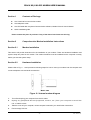
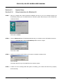
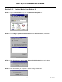
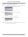
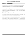
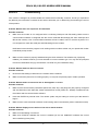
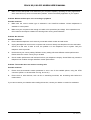
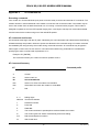
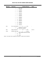
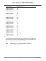
I306 V.92/V.90 PCI MODEM USER’S MANUAL
TABLE OF CONTENT
1. Contents of Package
2. Comprehensive Modem Installation Instructions
2.1
2.2
2.3
2.3.1
2.3.2
2.3.3
2.3.4
2.3.5
2.3.6
2.3.7
2.3.8
2.3.9
2.3.10
2.4
2.5
Modem Installation
Hardware Installation
System Setup
Setup Instructions for Windows 98
Uninstall Modem from Windows 98
Setup Instructions for Windows Me
Uninstall Modem from Windows Me
Setup Instructions for Windows NT4.0
Uninstall Modem from Windows NT4.0
Setup Instructions for Windows 2000
Uninstall Modem from Windows 2000
Setup Instructions for Windows XP
Uninstall Modem from Windows XP
Testing your modem
Install Communication Software
3. Troubleshooting
Appendix 1:
Appendix 2:
Appendix 3:
Appendix 4:
Appendix 5:
2
2
2
2
4
4
5
6
7
8
9
10
11
12
13
14
14
15
Modem Specifications..…..............….......17
AT Command Set ………...............……....17
S-Register Summary ……..............….......23
Result Codes Summary..…..............….....26
Government Compliance...............……....28
-1-
Rev.1.00.2.1.12
I306 V.92/V.90 PCI MODEM USER’S MANUAL
Section 1
Contents of Package
!
One V.92/V.90 PCI bus window modem
!
One telephone cable
!
One CD-ROM disk comprises Communication software, Modem Driver & User's Manual
!
Quick installation guide
Please contact the place of purchase if any of the above listed items are missing.
Section 2
Comprehensive Modem Installation Instructions
Section 2.1
Modem Installation
This section will provide instructions for the installation of your modem. There are hardware installation and
system setup two parts for the modem. The modem hardware must be installed into the computer correctly
before you start the system setup.
Section 2.2
Hardware Installation
Please refer to Fig. 2 - 1 and proceed to following steps for how to insert your modem into the computer and
connect telephone wire and audio accessories.
Model: I306
Figure 2-1 Internal modem diagram
1.
Turn off and unplug your computer from the AC outlet.
2.
Unplug any peripheral devices (keyboard, monitor, etc.) from your computer to avoid the
risk of electric shock.
3.
Take the cover off your computer, review computer's manual if you need further instructions.
4.
Find an empty PCI slot.
-2-
Rev.1.00.2.1.12
I306 V.92/V.90 PCI MODEM USER’S MANUAL
5.
Unscrew the PCI slot bracket and save the screw, then remove the bracket.
6.
Plug the modem into the PCI slot carefully until the modem is properly seated.
7.
Fasten the modem bracket firmly with the screw saved in step 5.
8.
Reassemble your computer cover and re-plug cables for peripheral.
9.
Plug one end of telephone cord into the "LINE" jack at the modem's bracket. Plug another end of the
telephone cord into the telephone wall jack
10. Some models may comprise a phone jack for an optional telephone. If you wish to use a phone through
the same telephone wall jack when the modem is not in use, plug the telephone cord of the phone into
"PHONE" jack at the modem's bracket now. Lift the handset and listen for a dial tone to check for a
properly connection.
11.
Plug the power cord into the computer and turn the computer on.
12. Up to now, the hardware installation has been finished. If you have not encountered any problems, you
can go to Section 2.3 System Setup. If you are having problems, see Section 3 Troubleshooting.
NOTE : The telephone wall jack you use must be for an ANALOG phone line (the type found in most homes).
Many offices are equipped with digital phone lines. Please be sure you know which type of line you have. The
modem will be damaged if you use a digital phone line.
-3-
Rev.1.00.2.1.12
I306 V.92/V.90 PCI MODEM USER’S MANUAL
Section 2.3
System Setup
Section 2.3.1
Setup instructions for Windows 98
STEP 1.
After you complete the modem hardware installation and turn on your PC, Windows system will
automatically detect your new added devices. Windows system will prompt you with an Add New
Hardware Wizard.
Then click on Cancel.
STEP 2.
Insert the Modem Driver CD-ROM disk attached with your modem into the CD-ROM drive device,
Then run <CD-ROM letter>:\drivers\Win98\Setup.exe as shown in figure.
Then click on OK
STEP 3.
And then, a prompt screen will ask you to ensure to install the modem driver.
Then click OK.
The setup utility will copy the needed files into windows system.
STEP 4.
If there is no error message while the system is installing, your modem has been set up properly
and functionally.
-4-
Rev.1.00.2.1.12
I306 V.92/V.90 PCI MODEM USER’S MANUAL
Section 2.3.2
Uninstall Modem from Windows 98
STEP 1.
Open Control Panel window, then click Add/Remove Programs icon.
STEP 2.
Choose Agere Systems PCI Soft Modem device in stall/Uninstall tab, then click on
Add/Remove… .
STEP 3.
Click Yes to ensure to remove Agere Systems PCI Soft Modem device and its drivers.
STEP 4.
Click Yes to restart your computer for all of the changes to take effect.
-5-
Rev.1.00.2.1.12
I306 V.92/V.90 PCI MODEM USER’S MANUAL
Section 2.3.3
STEP 1.
Setup instructions for Windows Me
After you complete the modem hardware installation and turn on your PC, Windows system will
automatically detect and install your new added devices. Windows system will prompt you with an
Add New Hardware Wizard.
Click on Cancel.
STEP 2.
Insert the Modem Driver CD-ROM disk attached with your modem into the CD-ROM drive device,
then run <CD-ROM letter>:\drivers\WinMe\SETUP.EXE to upgrade the modem driver as shown
in figure.
Then click on OK.
STEP 3.
And then, a prompt screen will ask you to ensure to install the modem driver.
Then click OK.
The setup utility will copy the needed files into windows system.
STEP 4.
If there is no error message while the system is installing, your modem has been set up properly
and functionally.
-6-
Rev.1.00.2.1.12
I306 V.92/V.90 PCI MODEM USER’S MANUAL
Section 2.3.4
Uninstall Modem from Windows Me
STEP 1.
Open Control Panel window, then click on Add/Remove Programs icon.
STEP 2.
Choose Agere Systems PCI Soft Modem device in Install/Uninstall tab, then click on
Add/Remove...
STEP 3.
Click Yes to ensure to remove Agere Systems PCI Soft Modem device and its drivers.
STEP 4.
Click Yes to restart your computer for all of the changes to take effect.
-7-
Rev.1.00.2.1.12
I306 V.92/V.90 PCI MODEM USER’S MANUAL
Section 2.3.5
STEP 1.
Setup instructions for Windows NT4.0
Insert the Modem Driver CD-ROM disk attached with your modem into the CD-ROM drive device,
Then run <CD-ROM letter>:\Drivers\ NT4\Setup.exe as shown in figure.
STEP 2.
And then, a prompt screen will ask you to ensure to install the modem driver.
Then click OK.
The setup utility will copy the needed files into windows system.
STEP 3.
The prompt screen will ask you to restart to enable the modem driver.
Then click on OK.
STEP 4.
The system will restart your system. If there is no error message while the system is re-booting,
your modem has been set up properly and functionally.
-8-
Rev.1.00.2.1.12
I306 V.92/V.90 PCI MODEM USER’S MANUAL
Section 2.3.6
Uninstall Modem from Windows NT4.0
STEP 1.
Open Control Panel window, then click Add/Remove Programs icon.
STEP 2.
Choose Agere Systems PCI Soft Modem device in stall/Uninstall tab, then click on
Add/Remove… .
STEP 3.
Click Yes to ensure to remove Agere Systems PCI Soft Modem device and its drivers.
STEP 4.
Click Yes to restart your computer for all of the changes to take effect.
-9-
Rev.1.00.2.1.12
I306 V.92/V.90 PCI MODEM USER’S MANUAL
Section 2.3.7
STEP 1.
Setup instructions for Windows 2000
After you complete the modem hardware installation and turn on your PC, Windows system will
automatically detect your new added devices. Windows system will prompt you with an Add New
Hardware Wizard.
Click on Cancel.
STEP 2.
Insert the Modem Driver CD-ROM disk attached with your modem into the CD-ROM drive device,
then run <CD-ROM letter>:\drivers\Win2K&XP\Setup.exe as shown in figure.
Then click on OK.
STEP 3.
And then, a prompt screen will ask you to ensure to install the modem driver.
Then click on OK.
The setup utility will copy the needed files into windows system.
STEP 4.
If there is no error message while the system is installing, your modem has been set up properly
and functionally.
- 10 -
Rev.1.00.2.1.12
I306 V.92/V.90 PCI MODEM USER’S MANUAL
Section 2.3.8
Uninstall Modem from Windows 2000
STEP 1.
Open Control Panel window and choose Add/Remove Programs icon.
STEP 2.
Select Agere Systems PCI Soft Modem device in Change or Remove Programs tab, then click
on Change/Remove.
STEP 3.
Click Yes to ensure to remove Agere Systems PCI Soft Modem device and its drivers.
STEP 4.
Click Yes to restart your computer for all of the changes to take effect.
- 11 -
Rev.1.00.2.1.12
I306 V.92/V.90 PCI MODEM USER’S MANUAL
Section 2.3.9
STEP 1.
Setup instructions for Windows XP
After you complete the modem hardware installation and turn on your PC, Windows system will
automatically detect and install your new added devices. Windows system will prompt you with an
Add New Hardware Wizard.
Click on Cancel.
STEP 2.
Insert the Modem Driver CD-ROM disk attached with your modem into the CD-ROM drive device,
Then run <CD-ROM letter>:\Drivers\Win2K&XP\SETUP.EXE to upgrade the modem driver as
shown in figure.
Then click on OK.
STEP 3.
And then, a prompt screen will ask you to ensure to install the modem driver.
Then click OK.
The setup utility will copy the needed files into windows system.
STEP 4.
If there is no error message while the system is installing, your modem has been set up properly
and functionally.
- 12 -
Rev.1.00.2.1.12
I306 V.92/V.90 PCI MODEM USER’S MANUAL
Section 2.3.10
Uninstall Modem from Windows XP
STEP 1.
Open Control Panel window, then click on Add or Remove Programs icon.
STEP 2.
Choose Agere Systems PCI Soft Modem device in Change or Remove Programs tab, then
click on Change/Remove.
STEP 3.
Click Yes to ensure to remove Agere Systems PCI Soft Modem device and its drivers.
STEP 4.
Click Yes to restart your computer for all of the changes to take effect.
- 13 -
Rev.1.00.2.1.12
I306 V.92/V.90 PCI MODEM USER’S MANUAL
Section 2.4
Testing Your Modem
Before you set up your software, start with a quick test to check that your modem is working. Once you have
determined that your modem is setup properly, go on to Section 2.5 Install Communication Software to
install your communications software. If you are having problems, see Section 3 Troubleshooting.
Click on Start and point to Setting. Then click on Control Panel. When the Control Panel window opens.
Scroll down to the Modem icon and double click on it. Click on the Diagnostics tab and highlight the COM
port for your modem. Then click on More Info, your computer will automatically communicate with your new
modem using AT commands and receiving responses from your modem. A list of response means the
modem is setup properly.
Section 2.5
Install Communication Software
You can install the communication software from the CD-ROM disc attached with your new modem. Please
consult the software manual in the CD-ROM disc for the detail of software installation.
You do not have to use the communication software attached with your new modem. The modem was
designed for and tested using a wide range of communications software packages. Many communication
applications identify the modem automatically and configure themselves for the correct operating settings.
Some of the communication applications will ask you to select the type of modem you are using. Select a
Generic Fax class 1 modem will let you use basic communication and fax functions.
- 14 -
Rev.1.00.2.1.12
I306 V.92/V.90 PCI MODEM USER’S MANUAL
Section 3
Troubleshooting
Your modem is designed to provide reliable and trouble-free functionality, however, should you experience
any difficulty, the information contained in this section will assist you in determining and resolving the source
of the problem.
Problem: Modem does not respond to AT commands
Possible solutions:
1.
Make sure the modem is not configured with a conflicting COM port and IRQ setting. Make sure the
communication software is configured with the correct COM and IRQ settings (the same COM port and
IRQ as the modem). Your communications software will not be able to send or receive any data if it is
not configured to match the COM port and IRQ settings for the modem.
DOS based communication program is not working with this modem neither can you operate the modem
in MS-DOS prompt screen.
2.
Make sure the modem is properly initialized using the driver software. The software may improperly
Initialize your modem because you have selected an incorrect modem type. You may also be prompted
to enter an initialization string by the software. Use AT&F as your initialization string.
Problem: Modem dials but does not connect
Possible solutions:
1.
Be sure the IRQ setting is identical on the modem and the software.
2.
Make sure that the phone line is working properly. A noisy line will prevent proper modem operation.
Problem: Modem makes a connection but no data appears on screen
Possible solutions:
1.
Make sure all communication parameters (baud rate, data, stop, and parity bits) are properly configured
and are identical on both sides. Be certain hardware flow control (RTS/CTS - default) is enabled in both
the modem and the communication software.
2.
Press the ENTER key several times. The remote system may be waiting to receive your data before it
begins.
3.
Make sure the correct terminal emulation mode is being used in the software (refer to software manual).
Problem: Modem displays errors while on-line with a remote modem
Possible solutions:
1.
Make sure Call Waiting is turned off.
2.
Make sure RTS/CTS hardware flow control is enabled (do not use XON/XOFF software flow control
when transferring binary files).
- 15 -
Rev.1.00.2.1.12
I306 V.92/V.90 PCI MODEM USER’S MANUAL
3.
Make sure the data speed is not faster than your computer capability. Operating too many applications
at the same time may cause communication problem. Close unnecessary application in your system.
Problem: Modem exhibits poor voice recording or playback
Possible solutions:
1.
Make sure the correct modem type is selected in the Voice/FAX software. Volume adjustment is
available in control panel.
2.
Make sure your computer is fast enough to handle voice operations (38.4 Kbps). Voice operations are
CPU intensive and require a better CPU sharing when running under Windows.
Problem: No dial tone
Possible solutions:
1.
Ensure that the telephone cord it securely connected at both modem and wall outlet.
2.
Unplug the telephone cord from the computer and connect it directly to a telephone from the wall outlet.
Check for a dial tone. If there is none, the problem is in the telephone cord or system. Call your
telephone service provider.
3.
Double-check your country setting. Different country setting will cause different modem performance.
Please select the correct country as you located.
4.
Check modem performance with a direct line from your telephone company. Some PBXs may cause the
telephone line condition change and affect modem performance.
Problem: The modem does not answer incoming calls
Possible solutions:
1.
Ensure that the automatic answer parameter is set to one of the enabled options, using the ATS0
command (ATS0=1 to answer after one ring, and so on).
2.
Ensure that no other devices, such as fax or answering machines, are answering calls before the
modem does.
If you cannot resolve your situation after reading this section, contact your dealer or vendor for assistance.
- 16 -
Rev.1.00.2.1.12
I306 V.92/V.90 PCI MODEM USER’S MANUAL
Appendix 1
Modem Specifications
Modulation standards: V.92, V.90, V.34, V.32bis, V.32, V.29, V.27ter, V.22bis, V.23,V.22, V.21,V.17,
Bell212/103
Compression
: V.44, V.42bis, MNP Class 5
Error Correction
: V.42, MNP Class 2-4
Host Interface
: PCI bus
FAX Group
: Group III
FAX Command
: EIA/TIA 578 class 1
- 17 -
Rev.1.00.2.1.12
I306 V.92/V.90 PCI MODEM USER’S MANUAL
Appendix 2
AT command set
Executing commands
Your modem is in Command Mode upon power-on and is ready to receive and execute AT commands. The
modem remains in Command Mode until it makes a connection with a remote modem. Commands may be
sent to the modem from an attached terminal or a PC running a communication program. This modem is
designed to operate at common DTE speeds ranging from 115.2 Kbps to 300 bps. All commands and data
must be issued to the modem using one of the valid DTE speeds.
AT commands and format
All commands must begin with the AT prefix, followed by the command letter and ended with the ENTER key.
All default settings are printed in bold text. Spaces are allowed in the command string to increase command
line readability but are ignored by the modem during command execution. All commands may be typed in
either upper or lower case, but not mixed. A command issued without any parameters is considered as
specifying the same command with a parameter of "0".
Example: ATL [ENTER]
This command causes your modem to lower its speaker volume.
AT Command Summary
AT
Command prefix
A/
Repeat last command
A
Answer
B0
Select V.22/V.21
B1
Select B212A/B103
B15
Select V.21 when the modem is at 300 BPS
B16
Select Bell 103J when the modem is at 300 BPS
D
Dial
0-9
Dialing digits
ABCD*#
Tone dial characters
L
Redial last number
P
Pulse dial
T
Tone dial
V
The modem switches to speakerphone mode and dials the number
R
The modem goes into answer mode directly after finish dialing
S=n
Dial stored telephone number n
W
Wait for dial tone
- 18 -
Rev.1.00.2.1.12
I306 V.92/V.90 PCI MODEM USER’S MANUAL
AT
Command prefix
,
Pause the time specified in S-register S8
!
Flash hook
@
Wait for quiet answer
^
Disable data calling tone transmission
$
Bong tone detection
;
Return to command mode
E0
Disables echo
E1
Enables echo
H0
Hang up the telephone line
H1
Pick up the telephone line
I0
Reports modem identify string and driver version number
I1
Calculate ROM checksum and report it to DTE
I2
Verifies ROM checksum and report OK or ERROR
I3
Report modem identify string and driver version number
I4
Report firmware version for datapump
I5
Report the board/firmware ID, country ID and subsystem vendor ID
I9
Report country ID
I11
Report connection information
L0
Low speaker volume
L1
Low speaker volume
L2
Medium speaker volume
L3
High speaker volume
M0
Speaker always off
M1
Speaker on until carrier present
M2
Speaker always on
M3
Speaker off during dialing; speaker on until carrier present
N0
Handshake only at the communication standard specified by S37 and
ATB command
N1
Begin the handshake at the communication standard specified by s37 and ATB,
and fallback to lower speed may occur
O0
Return to data mode
O1
Retrain and return to data mode
O3
Rate re-negotiation and return to data mode
P
Select pulse dialing
Q0
Enables result code
Q1
Disables result code
Sn
Select S-register n; refer to S-register summary for the details
- 19 -
Rev.1.00.2.1.12
I306 V.92/V.90 PCI MODEM USER’S MANUAL
AT
Command prefix
Sn=x
Write x to S-register n; refer to S-register summary for the details
Sn?
Read from S-register n; refer to S-register summary for the details
T
Select tone dialing
V0
Choose numeric form result code
V1
Choose verbose form result code
W0
Reports DTE connect speed result code, disable protocol result codes
W1
Reports DTE connect speed result code, enable protocol result codes
W2
Reports DCE connect speed result code, enable protocol result codes
X0
Enables result code 0-4; disables dial tone and busy tone detection
X1
Enables result code 0-5,10 and above; disables dial tone and busy tone detection
X2
Enables result code 0-6, 10 and above; enables dial tone detection and disables busy
tone detection
X3
Enables result code 0-5,7,10 and above; disables dial tone detection and enables busy
tone detection
X4
Enables result code 0-7, 10 and above; enables dial tone and busy tone detection
Z
Reset modem and recalls user profile
&C0
Ignores carrier status; CD always ON
&C1
CD set according to carrier status
&D0
Ignores DTR
&D1
Modem switches from data mode to command mode when an ON-to-OFF transition of
DTR occurs
&D2
When DTR switches OFF , the modem goes on-hook and disables
auto-answer
&D3
Reset modem and recall user profile when DTR switches OFF
&F
Load factory defaults
&G0
Disables guard tone
&G1
Enables 550 Hz guard tone
&G2
Enables 1800 Hz guard tone
&K0
Disables flow control
&K3
Enables CTS/RTS hardware flow control
&K4
Enables XON/XOFF software flow control
&M0
Select asyncronous buffer mode
&P0
Select 10 pps pulse dial with 39%/61% make/break ratio
&P1
Select 10 pps pulse dial with 33%/67% make/break ratio
&P2
Select 20 pps pulse dial with 33%/67% make/break ratio
&Q0
Select asynchronous buffer mode
&Q5
Select Error control mode
- 20 -
Rev.1.00.2.1.12
I306 V.92/V.90 PCI MODEM USER’S MANUAL
AT
Command prefix
&Q6
Same as &Q0
&Q8
Select MNP error control mode. If fail to connect, the modem will fallback according to
current setting in S36
&Q9
Select V42 or MNP error control mode. If fails to establish, the modem will fallback
according to current setting in S36
&S0
DSR always ON
&S1
DSR ON only during handshaking and when carrier is lost
&T0
Terminates test in progress
&T1
Initiates local analog loopback(LAL)
&T3
Initiates local digital loopback
&T6
Initiates remote digital loopback(RDL)
&V
View active profile, stored user profile and stored telephone number
&W
Stores active profile into user profile
&Zn=x
Stores telephone number x(up to 40 digits) to location n(0-3).I301 V.90
%B
View number in blacklist
%C0
Disables data compression
%C1
Enables data compression
%E0
Disables fallback and fall forward
%E1
Enables fallback, disables fall forward
%E2
Enables fallback and fall forward
-C0
Disables calling tone
-C1
Enables 1300 Hz calling tone
-V90=n
Control V.90 downstream speed
n=0
V.90 disabled
n=1
Auto rate
n=2
28000 BPS
n=3
29333 BPS
n=4
30666 BPS
n=5
32000 BPS
n=6
33333 BPS
n=7
34666 BPS
n=8
36000 BPS
n=9
37333 BPS
n = 10
38666 BPS
n = 11
40000 BPS
n = 12
41333 BPS
n = 13
42666 BPS
- 21 -
Rev.1.00.2.1.12
I306 V.92/V.90 PCI MODEM USER’S MANUAL
AT
Command prefix
n = 14
44000 BPS
n = 15
45333 BPS
n = 16
46666 BPS
n = 17
48000 BPS
n = 18
49333 BPS
n = 19
50666 BPS
n = 20
52000 BPS
n = 21
53333 BPS
-V90?
Reports current V.90 setting
\A0
Set maximum MNP block size to 64 characters
\A1
Set maximum MNP block size to 128 characters
\A2
Set maximum MNP block size to 192 characters
\A3
Set maximum MNP block size to 256 characters
\Bn
Transmit break in n*100ms (n = 0-9)
\G0
Disables XON/XOFF flow control between local and remote modems
\G1
Enables XON/XOFF flow control between local and remote modems
\J0
Disables DTE speed adjust
\J1
Enables DTE speed adjust
\Kn
Set break control (n=0-5, default is 5).
\N0
Select normal mode
\N1
Select normal mode
\N2
Select MNP reliable mode
\N3
Select V.42 auto-reliable mode
\N4
Select V.42 reliable mode
\Q0
Disables flow control
\Q1
Enables XON/XOFF software flow control
\Q2
Enables CTS hardware flow control
\Q3
Enables CTS/RTS hardware flow control
\Tn
Set inactivity timer in minutes(n=0-255, default is 0)
\V0
Disables protocol result code appended to DCE speed
\V1
Enables protocol result code appended to DCE speed
\X0
Process XON/XOFF character as flow control character only
\X1
Process XON/XOFF character as flow control character and pass through to local DTE
or remote modem
Notes:
The default setting of commands is in bold Italic text format.
- 22 -
Rev.1.00.2.1.12
I306 V.92/V.90 PCI MODEM USER’S MANUAL
Appendix 3
S-Register Summary
Register
Function
Default Range
S0*
No. of rings to start auto-answer 0
0-255
ring
S1*
Ring count
0
0-255
ring
S2*
Escape character
43
0-255
ASCII
S3
Carriage return character
13
0-127
ASCII
S4
Line feed character
10
0-127
ASCII
S5
Backspace character
8
0-32,127
ASCII
S6*
Wait before dialing
2
2-65
second
S7*
Wait for carrier
50
1-255
second
S8*
Pause time for dial modifier ,
2
0-65
second
S10*
Lost carrier hang up delay
20
1-254
0.1second
S11*
DTMF dialing speed
95
50-150
msec
S12*
Escape guard time
50
0-255
20 msec
S14*
Bit-mapped register
-
0-255
-
Bit 0,1,2
Bit 3
Reserved
=
0
V0 is selected
=
1
V1 is selected
Bit 4,5
Bit 6
Reserved
=
0
10 PPS pulse dialing(&P0, &P1)
=
1
20 PPS pulse dialing(&P2)
Bit 7
S21*
Reserved
Bit-mapped register
Bit0,1,2
Bit 4-3
Bit 5
-
=
00
&D0 is selected
=
01
&D1 is selected
=
10
&D2 is selected
=
11
&D3 is selected
=
0
&C0 is selected
=
1
&C1 is selected
-
0-255
-
Reserved
Bit-mapped register
Bit 0,1,2,3
Bit 6-4
0-255
Reserved
Bit 6,7
S22*
Units
Reserved
=
000 X0 is selected
=
001 Reserved
=
010 Reserved
=
011 Reserved
=
100 X1 is selected
- 23 -
Rev.1.00.2.1.12
I306 V.92/V.90 PCI MODEM USER’S MANUAL
Register
Function
Bit 7
S28*
Default Range
Units
=
101 X2 is selected
=
110 X3 is selected
=
111 X4 is selected
=
0
33/67 M/B ratio is selected(&P1, &P2)
=
1
39/61 M/B ratio is selected(&P0)
Control V.34 modulation
1
0-1
=
0
Disables V.34 modulation
=
1
Enables V.34 modulation
-
S30*
Inactivity timer
0
0-255
minute
S32*
Synthetic ring volume
10
0-255
-
S33*
Synthetic ring frequency
0
0-5
-
S35*
Data calling tone
0
0-1
S37*
S38*
=
0
Disables data calling
=
1
Enables data calling
Maximum line speed attempted 0
=
0
Auto rate
=
1
Reserved
=
2
1200/75 bps
=
3
300 BPS
=
4
Reserved
=
5
1200 BPS
=
6
2400 BPS
=
7
4800 BPS
=
8
7200 BPS
=
9
9600 BPS
=
10
12000 BPS
=
11
14400 BPS
=
12
16800 BPS
=
13
19200 BPS
=
14
21600 BPS
=
15
24000 BPS
=
16
26400 BPS
=
17
28800 BPS
=
18
=
19
0
-
31200 BPS
33600 BPS
K56flex downstream rate
=
0-19
1
0-14
-
Disables K56flex
- 24 -
Rev.1.00.2.1.12
I306 V.92/V.90 PCI MODEM USER’S MANUAL
Register
S48*
Function
=
1
Auto rate
=
2
32K BPS
=
3
34K BPS
=
4
36K BPS
=
5
38K BPS
=
6
40K BPS
=
7
42K BPS
=
8
44K BPS
=
9
46K BPS
=
10
48K BPS
=
11
50K BPS
=
12
52K BPS
=
13
54K BPS
=
14
56K BPS
Error control feature
Default Range
Units
7
7,128
-
=
7
Negotiation enabled
=
128 Negotiation disabled
S89*
Sleep mode timer
10
0,5-65
second
S108 *
Network codec type
7
7,22,33
-
=
7
Specified by central site mode
=
22
u-law
=
33
A-law
Notes : The value of the S-registers marked with (*) were saved in NVRAM
- 25 -
Rev.1.00.2.1.12
I306 V.92/V.90 PCI MODEM USER’S MANUAL
Appendix 4
Result Codes Summary
Verbose Code
Numeric Code
OK
0
CONNECT
1
RING
2
NO CARRIER
3
ERROR
4
CONNECT 1200 EC*
5
NO DIAL TONE
6
BUSY
7
NO ANSWER
8
DELAYED
88
BLACKLISTED
89
BLACKLIST FULL
90
CONNECT 300 EC*
40
CONNECT 2400 EC*
10
CONNECT 4800 EC*
11
CONNECT 7200 EC*
24
CONNECT 9600 EC*
12
CONNECT 12000 EC*
25
CONNECT 14400 EC*
13
CONNECT 16800 EC*
86
CONNECT 19200 EC*
14
CONNECT 21600 EC*
55
CONNECT 24000 EC*
56
CONNECT 26400 EC*
57
CONNECT 28000 EC*
100
CONNECT 28800 EC*
58
CONNECT 29333 EC*
101
CONNECT 30666 EC*
102
CONNECT 31200 EC*
59
CONNECT 32000 EC*
70
CONNECT 33333 EC*
103
CONNECT 33600 EC*
60
CONNECT 34000 EC*
71
CONNECT 34666 EC*
104
CONNECT 36000 EC*
72
CONNECT 37333 EC*
105
- 26 -
Rev.1.00.2.1.12
I306 V.92/V.90 PCI MODEM USER’S MANUAL
Verbose Code
Numeric Code
CONNECT 38000 EC*
73
CONNECT 38400 EC*
28
CONNECT 38666 EC*
106
CONNECT 40000 EC*
74
CONNECT 41333 EC*
107
CONNECT 42000 EC*
75
CONNECT 42666 EC*
108
CONNECT 44000 EC*
76
CONNECT 45333 EC*
109
CONNECT 46000 EC*
77
CONNECT 46666 EC*
110
CONNECT 48000 EC*
78
CONNECT 49333 EC*
111
CONNECT 50000 EC*
79
CONNECT 50666 EC*
112
CONNECT 52000 EC*
80
CONNECT 53333 EC*
113
CONNECT 54000 EC*
81
CONNECT 54666 EC*
114
CONNECT 56000 EC*
82
CONNECT 57600 EC*
18
CONNECT 115200 EC*
87
Note:
* EC only appear when the extended result codes configuration option is enabled. EC is
replaced by one of the following symbols, depending upon the error control method used:
V.42bis
- V.42 error control and V.42bis data compression.
V.42
- V.42 error control only.
MNP5
- MNP class 4 error control and MNP class 5 data compression.
MNP4
- MNP class 4 error control only.
NoEC
- No error control protocol.
- 27 -
Rev.1.00.2.1.12
I306 V.92/V.90 PCI MODEM USER’S MANUAL
Appendix 5 Government compliance notices
FCC compliance
This equipment complies with Part 68 of the FCC Rules. On this equipment is a label that contains, among
other information, the FCC registration number and Ringer Equivalence Number (REN) for this equipment.
You must, upon request, provide this information to your telephone company.
If your telephone equipment causes harm to the telephone network, the Telephone Company may discontinue
your service temporarily. If possible, they will notify in advance. But, if advance notice isn’t practical, you will
be notified as soon as possible. You will be informed of your right to file a complaint with the FCC.
Your telephone company may make changes in its facilities, equipment, operations, or procedures that could
affect proper operation of your equipment. If they do, you will be notified in advance to give you an opportunity
to maintain uninterrupted telephone service.
The FCC prohibits this equipment to be connected to party lines or coin-telephone service.
In the event that this equipment should fail to operate properly, disconnect the equipment from the phone line
to determine if it is causing the problem. If the problem is with the equipment, discontinue use and contact
your dealer or vendor.
FCC Class B statement
This equipment has been tested and found to comply with the limits for a Class B digital device, pursuant to
Part 15 of the FCC Rules. These limits are designed to provide reasonable protection against harmful
interference in a residential installation. This equipment generates, uses and can radiate radio frequency
energy, and if not installed and used in accordance with the instructions, may cause harmful interference to
radio communications. However, there is no guarantee that interference will not occur in a particular
installation. If this equipment does cause harmful interference to radio or television reception, which can be
determined by turning the equipment off and on, the user is encouraged to try to correct the interference by
one or more of the following measures:
Reorient or relocate the receiving antenna.
Increase the separation between the equipment and the receiver.
Connect the equipment into an outlet on a circuit different from that to which the receiver is connected.
Consult the dealer or an experienced radio/TV technician for help.
Notice: 1) Shielded cables, if any, must be used in order to comply with the emission limits.
2) Any change or modification not expressly approved by the Grantee of the equipment
authorization could void the user s authority to operate the equipment.
- 28 -
Rev.1.00.2.1.12
I306 V.92/V.90 PCI MODEM USER’S MANUAL
DOC compliance information
NOTICE: The Canadian Department of Communications label identifies certified equipment. This certification
means that the equipment meets certain telecommunications network protective, operational and safety
requirements. The Department does not guarantee the equipment will operate to the user’s satisfaction.
Before installing this equipment, users ensure that it is permissible to be connected to the facilities of the local
Telecommunications Company. The equipment must also be installed using an acceptable method of
connection. The customer should be aware that compliance with the above conditions might not prevent
degradation of service in some situations.
Repairs to certified equipment should be made by an authorized Canadian maintenance facility designated by
the supplier. Any repairs or alterations made by the user to this equipment, or equipment malfunctions, may
give the telecommunications company cause to request the user to disconnect the equipment.
Users should ensure for their own protection that the electrical ground connections of the power utility,
telephone lines and internal metallic water pipe system, if present, are connected together. This precaution
may be particularly important in rural areas.
CAUTION: Users should not attempt to make such connections themselves, but should contact the
appropriate electric inspection authority, or electrician, as appropriate.
NOTICE: The Load Number (LN) assigned to each terminal device denotes the percentage of the total load to
be connected to a telephone loop which is used by the device, to prevent overloading. The termination on a
loop may consist of any combination of devices subject only to the requirement that the sum of the Load
Numbers of all the devices does not exceed 100.
European CTR 21 compliance
The equipment has been approved in accordance with Council Decision 98/482/EC for pan-European single
terminal connection to the public switched telephone network (PSTN). However, due to differences between
the individual PSTNs provided in different countries, the approval does not, of itself, give an unconditional
assurance of successful operation on every PSTN network termination point. In the event of problem, you
should contact your equipment supplier in the first instance.
Note: The manufacturer should ensure that the vendor and user of the equipment is clearly informed of the
above information by means of package and /or user manuals of the forms of user instructions.
- 29 -
Rev.1.00.2.1.12