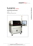
1
V-Flow Line operating instructions Variable area flowmeters Handbuch PCU1000 and high-precision control valves for gases and liquids Vögtlin Instruments AG – flow technology Langenhagstrasse 1 | 4147 Aesch (Switzerland) Phone 41 (0)61 756 63 00 | Fax +41 (0)61 756 63 01 www.voegtlin.com | [email protected] V-Flow Line Operating instructions V-Flow Line Variable area flowmeters Q-Flow Variable area flowmeters V-100 High-precision control valves M-Flow Version: vflow_E4_7 For the latest information on our products, see our website at www.voegtlin.com © 2010 Vögtlin Instruments AG, Switzerland Manual Version V-Flow Line vflow_E4_7 Page © Vögtlin Instruments AG 02 V-Flow Line Contents Introduction 5 Service and quality 5 Warranty 5 General instructions 6 Safety information 6 Using the manual 6 General information 7 Operating principle of the variable area flowmeter 7 Variable area flow meter type marking 8 High-precision control valve type marking 8 Technical data 9 Technical data Q-Flow 9 Materials Q-Flow 9 Setups Q-Flow 9 Technical data V-100 10 Materials V-100 10 Setups V-100 10 Technical data M-Flow 11 Materials M-Flow 11 Setups M-Flow 11 M-Flow valve operation options 12 Measuring ranges variable area flowmeters 13 Measuring ranges direct reading scales ln/h (Air) and l/h (Water) 13 Measuring ranges direct reading scales mln/min and ln/min (Air) 14 Measuring ranges mm-scale Q-Flow 14 Measuring ranges mm-scale V-100 14 CV-values high-precision control valves M-Flow 15 Installation and commissioning 16 General instructions 16 Installation instructions 18 Instructions for commissioning 18 Recommended connections 18 Panel mounting Q-Flow 19 Faceplate mounting V-100 20 Limit indicator 21 M-Flow Digiturn installation 24 Manual Version V-Flow Line vflow_E4_7 Page © Vögtlin Instruments AG 03 V-Flow Line Disassembly and maintenance 25 Important instructions 25 Disassembly variable area flowmeter Q-Flow 25 Disassembly variable area flowmeter V-100 26 Disassembly Digiturn M-Flow 27 Maintenance 28 Soiling 28 Cleaning 28 Return 28 Appendix 29 Dimensions Q-Flow 29 Dimensions V-100 30 Dimensions M-Flow 31 Type code Q-Flow 33 Type code V-100 34 Type code M-Flow 35 Contamination declaration 37 Manual Version V-Flow Line vflow_E4_7 Page © Vögtlin Instruments AG 04 V-Flow Line Introduction We are glad that you have decided to use our variable area flow meters and high-precision control valves. Our instruments will provide you with high-quality long-lived products. This manual contains important information for commissioning and/or designing equipment. Please contact your distribution partner if anything is not clear. We are committed to the continual improvement of our products and documentation. Your experience from everyday use can assist us with this. We welcome your comments and criticisms. We have taken great care in compiling this manual. However, we cannot accept responsibility for possible errors. Service and quality We are continually improving the quality and provision of our products and services. In the end, whether the right product was selected only becomes apparent once the product is in use. Therefore we make every effort not just to preach but also to live by top quality and service. Warranty The warranty for the products described in this manual is limited to defects in material and workmanship. Warranty does in no case exceed product replacement free of charge. All claims are null and void in the case of improper use: Use outside the operating limits Damage due to water hammer Corrosion damage Mechanical damage in general Manual Version V-Flow Line vflow_E4_7 Page © Vögtlin Instruments AG 05 V-Flow Line General instructions Check the package for external damage and contact your distribution partner if the instruments have visible defects. Check that the delivery is complete and corresponds to the delivery note. This product is a precision measuring instrument. We would like to point out that you should take due care when choosing the installation site and following these suggestions and instructions. Before installing, check that the specification on the type label matches your application. Please read through these operating instructions carefully before commissioning. Incorrect operation, errors in comprehension and the consequences of these can lead to breakage of the instrument or risk of personal injury. Commissioning and maintenance must be carried out by appropriately qualified personnel. Proper use of the products is a necessary precondition for their smooth operation. Safety information The instruments must not be used outside the specified operating limits (See also section Technical Data) Incorrect operation can lead to breakage of the instrument or risk of personal injury. When using toxic media it is strongly advised not to use glass cylinder measuring instruments: cylinder breakage and leaks can cause risk of personal injury Shocks, e.g. caused by magnetic valves, should be avoided. The measuring instruments must be used solely for the medium specified in the delivery note. Media which differ from this may lead to impaired durability and therefore cause leakage Using the manual This manual contains information on the variable area flowmeters Q-Flow and V-100 and highprecision control valves M-Flow. Sections and paragraphs which only apply to a particular product group are marked as follows: Variable area flowmeters Q-Flow Variable area flowmeters V-100 High-precision control valves M-Flow Manual Version V-Flow Line vflow_E4_7 Page © Vögtlin Instruments AG 06 V-Flow Line General information Operating principle of the variable area flowmeter The measuring instrument works according to the float measuring principle The measuring unit consists of a tapered graduated precision glass measuring cylinder in which a ball float can move freely up and down. The medium flows through the vertically-aligned measuring cylinder from the bottom upwards. The float positions itself so that the buoyancy force A acting on it, the form resistance W and its weight G are in balance:: G=A+W The flow rate can be read as the height of the float on a scale on the tapered measuring cylinder. The value is read off at the middle of the float (largest diameter). Manual Version V-Flow Line vflow_E4_7 Page © Vögtlin Instruments AG 07 V-Flow Line Variable area flow meter type marking The instrument type label is attached to the inside of the left side panel in the V-100 and on the back of the mounting plate in the Q-Flow: Example: SN: 483493-1-006 BE: 133526 Type: FLV-CSSA-SM 07/08 Air, 3.6-43 ln/min, 4 bar a, 20°C mm-Scale www.voegtlin.com - +41 61 756 63 00 Key: SN: BE: 07/08: Type: Serial number – Position – number of instruments per position Customer order number Date of manufacture, month/year Specification in accordance with type code (standard instruments only) 1 Medium, measuring range, measurement unit, pressure, temperature and additional information. 1 Custom designed instruments are given a seven digit product code instead of a type code (e.g. 137-1215). High-precision control valve type marking For the M-Flow the type label is attached to the valve cartridge housing. An arrow on the body of the valve indicates the flow direction. Example: Key: NS 2.5: L: V: Specification of valve size NS 1.0 to NS 6.5 Closing direction for valve (L = left / R = right) Sealing material (V = FKM / E = EPDM / P = FFKM Custom designed instruments can have additional details such as leakage rate. Manual Version V-Flow Line vflow_E4_7 Page © Vögtlin Instruments AG 08 V-Flow Line Technical data Technical data Q-Flow Type Q-Flow 55 Q-Flow 80 Q-Flow 140 10:1 10:1 10:1 Accuracy in % of full scale ±5% ±4% ±2% Measuring tube length 55 mm 80 mm 140 mm Scale length 40 mm 65 mm 120 mm spherical spherical spherical Max. pressure 20 bar 20 bar 16 bar Max. pressure drop 100°C 100°C 100°C Turndown ratio Float Materials Q-Flow Component Aluminium Stainless steel Top and base sections* Anodized aluminum Stainless steel 1.4305 Mounting plate Anodized aluminum Anodized aluminum Borosilicate glass Borosilicate glass Nickel-plated brass Stainless steel 1.4305 Float* SS 316 L / Glass / Ceramic SS 316 L / Glass / Ceramic Valve* Nickel-plated brass Stainless steel 1.4305 Seals* FKM FKM/EPDM Makrolon (Polycarbonate) Makrolon (Polycarbonate) Measuring cylinder* Connections* Front cover Shock absorbing limit stop* Stainless steel 1.4305 / PTFE Stainless steel 1.4305 / PTFE *Wetted parts Setups Q-Flow Standard (process connection on the back) With valve Without valve Manual Version V-Flow Line vflow_E4_7 Page © Vögtlin Instruments AG 09 V-Flow Line Technical data V-100 Type V-100 55 V-100 80 V-100 140 10:1 10:1 10:1 Accuracy in % of full scale ±5% ±4% ±2% Measuring tube length 55 mm 80 mm 140 mm Scale length 40 mm 65 mm 120 mm spherical spherical spherical Max. pressure 20 bar 20 bar 16 bar Max. pressure drop 100°C 100°C 100°C Turndown ratio Float Materials V-100 Component Aluminium Stainless steel Top and base sections* Anodized aluminum Stainless steel 1.4305 Mounting plate Anodized aluminum Anodized aluminum Borosilicate glass Borosilicate glass Nickel-plated brass Stainless steel 1.4305 Float* SS 316 L / Glass / Ceramic SS 316 L / Glass / Ceramic Valve* Nickel-plated brass Stainless steel 1.4305 Seals* FKM FKM/EPDM Makrolon (Polycarbonate) Makrolon (Polycarbonate) Measuring cylinder* Connections* Front cover Shock absorbing limit stop* Stainless steel 1.4305 / PTFE Stainless steel 1.4305 / PTFE *Wetted parts Setups V-100 (position of the process connection) Standard Setup L Setup R Setup A* Setup T* Setup O* *A, T and O-Type in stainless steel only Manual Version V-Flow Line vflow_E4_7 Page © Vögtlin Instruments AG 10 V-Flow Line Technical data M-Flow Type M-Flow 25 Straight valve Corner valve Valve insert/cartridge M-Flow 35 M-Flow V-Stack Gas distribution system Ccw-closed Valve turns 15 15 15 Valve size NS 1.0 bis 3.0 NS 4 und 6.5 NS 4 und 6.5 Leak rate <1x10 mbar l/s He <1x10 mbar l/s He <1x10 mbar l/s He Max. pressure 20 bar 20 bar 20 bar Min. temperature -40°C -40°C -40°C Max. temperature 150°C 150°C 150°C -5 -5 -5 Materials M-Flow Component Aluminium Edelstahl Valve* Anodized aluminum Stainless steel 1.4305 Valve insert/cartdrige * Nickel-plated brass Stainless steel 1.4305 Connections* Nickel-plated brass Stainless steel 1.4305 FKM FKM/EPDM/FFKM Seals* * Wetted parts Setups M-Flow Straight valve Corner valve Manual Version V-Flow Line vflow_E4_7 Distribution system V-Stack Page © Vögtlin Instruments AG 11 V-Flow Line M-Flow valve operation options The following valve operation options are available (see also the type code of each instrument): Standard-knob Standard-knob with locking ring manual knob manual knob stop ring 518-1552 disc Ø10x6.4/0.5 518-1550 basic valve right- or left-handed thread made from brass or stainless steel headless screw M3x6 512-8204 headless screw M3x6 512-8204 Hex socket and locking nut (instead of standard-knob) locking nut 518-1554 Digiturn with indication (100 divisions, cw-closed valve only) reducing bush 518-1575 cover ring 633-1104 Digi-knob (100 divisons, ccw-closed valve only) stargrip to digiturn knob 633-1103 digibase 518-1553 2 x headless screw M3x3 512-8201 collar ring 518-1563 digivö knob 633-1101 2 x headless screw M3x4 512-8202 digiturn knob 633-1102 2 x headless screw M4x10 512-8217 2 x headless screw M3x3 512-8201 Manual Version V-Flow Line vflow_E4_7 headless screw M5x5 Page © Vögtlin Instruments AG 12 V-Flow Line Measuring ranges variable area flowmeters Measuring ranges direct reading scales ln/h (Air) and l/h (Water) Medium Air, ln/h 1.21 bara, 20°C Conditions Type Water, l/h 20°C Q-Flow 55 V-100 55 Q-Flow 80 V-100 80 Q-Flow 140 V-100 140 Q-Flow 55 V-100 55 Q-Flow 140 V-100 140 0.12-1.2 0.12-1.2 - - - 0.2-2 0.2-2 0.2-2 - - 0.3-3 0.3-3 0.3-3 - - 0.5-5 0.5-5 0.5-5 - - 0.8-8 0.8-8 0.8-8 - - 1.6-16 1.6-16 1.6-16 - - 4-40 4-40 4-40 - - 6-60 6-60 6-60 0.25-2.5 0.25-2.5 10-100 10-100 10-100 0.5-5 0.5-5 25-250 25-250 25-250 1.2-12 1.2-12 50-500 50-500 50-500 2.5-25 2.5-25 80-800 80-800 80-800 4-40 4-40 120-1200 120-1200 120-1200 6-60* 6-60 140-1400* - 140-1400* 7-70* 7-70 - - 200-2000* - - *ranges available for V-100 instruments only Manual Version V-Flow Line vflow_E4_7 Page © Vögtlin Instruments AG 13 V-Flow Line Measuring ranges direct reading scales mln/min and ln/min (Air) Medium Air, mln/min Conditions 1.013 bara, 20°C Type Q-Flow 80 / V-100 80 Q-Flow 140 / V-100 140 10-120 10-100 20-240 40-220 60-640 50-540 Medium Air, ln/min Conditions 1.013 bara, 20°C Type Q-Flow 80 / V-100 80 Q-Flow 140 / V-100 140 0.1-1 0.1-1 0.3-2.2 0.2-2.2 0.5-5 0.5-6.0 0.2-10 1.5-10.5 2-20 2-26 4-32 6-51 Measuring ranges mm-scale Q-Flow Medium Conditions Measuring range Air, ln/h Water, l/h 1.21 bara, 20°C 20°C smallest highest smallest highest Q-Flow 80 0.04 – 1.75 850 – 3000 0.001 – 0.03 0.8 – 40 Q-Flow 140 0.15 – 2.25 500 – 5000 0.002 – 0.03 12 – 150 Measuring ranges mm-scale V-100 Medium Conditions Measuring range Air, ln/h Water, l/h 1.21 bara, 20°C 20°C smallest highest smallest highest V-100 80 0.04 – 1.75 100 – 5000 0.0005 – 0.015 10 – 100 V-100 140 0.15 – 2.25 500 – 5000 0.001 – 0.018 12 – 150 Manual Version V-Flow Line vflow_E4_7 Page © Vögtlin Instruments AG 14 V-Flow Line CV-values high-precision control valves M-Flow CV-values valves NS1.0 to NS6.5 1 0.1 0.01 cv-values 0.001 0.0001 NS-1.0 NS-1.5 NS-2.0 NS-2.5 NS-3.0 NS-4.0 NS-6.5 0.00001 0.000001 0.0000001 0 2 4 6 8 10 12 14 16 spindle turns 3 CV-value 1 = 1 m /h water at Δp of 1bar Manual Version V-Flow Line vflow_E4_7 Page © Vögtlin Instruments AG 15 V-Flow Line Installation and commissioning General instructions Measuring instrument design In addition to the type code (see appendix) we require you to supply the following information for optimal design of the instrument: Medium Maximum flow rate For design without valve: Pressure in measuring cylinder For design with valve: Pressure before and after the control valve Temperature When should the control valve be mounted at the outlet? In vacuum processes the gas expands considerably. This leads to significant measurement errors. The control valve should therefore always be placed at the outlet for vacuum applications. Liquids often contain gas bubbles. These settle on the float. This results in a higher flow rate being displayed. By installing the control valve at the outlet the gas bubbles become smaller and are better able to flow past the float. In the case of fluctuating back pressure (e.g. when gassing a liquid container if the level varies markedly). In the case of pulsating media or smaller water hammer the valve at the outlet has a cushioning effect. When should the control valve be mounted at the inlet? In the case of constant after-pressure If the control valve also has to serve as a locking valve. (e.g. if a measuring cylinder has to be exchanged when installed). Direct reading scale or mm-scale? The direct reading scale (also known as the product scale) is determined for only one operating condition. The mm-scale is not dependent on the medium, pressure and temperature. Different tables with various operating conditions can be used. The actual measurement value is not visible directly on the instrument but is read using a conversion table. Manual Version V-Flow Line vflow_E4_7 Page © Vögtlin Instruments AG 16 V-Flow Line What is the purpose of standard liters and norm liters? In contrast to liquids, gases can be compressed, so it is important to know the density of the gas used. This in turn is dependent on pressure and temperature, i.e. if two quantities of gas are to be compared with one another, then the current pressure in the pipe and the current temperature of the medium must be known. We supply general tables relating to norm liters 0°C 1013 mbar a The two quantities are defined as follows: Unit Pressure Temperature Standard liter 1013.25 mbar a 20°Celsius Norm liter 1013.25 mbar a 0° Celsius The US standard liter corresponds to the German norm liter (0°C 1013.25 mbar a). However, there are other reference temperatures. Gas suppliers use a reference temperature of 15 °C. Conversion of standard liter (Stdl) into norm liter (ln) and vice versa: Stdl = (ln/273.15)*293.15 ln = (Stdl/293.15)*273.15 Further information on this subject is given in the FAQs at www.voegtlin.com Manual Version V-Flow Line vflow_E4_7 Page © Vögtlin Instruments AG 17 V-Flow Line Installation instructions Before installing the measuring instrument, the pipe must be free of particles and moisture The variable area flowmeter must be installed in a vertical position The direction of flow is from the bottom upwards The measuring instrument must be installed stress-free. Please use the mounting holes provided for this purpose The process connections must not be sealed with sealing tape or liquid sealer. Residues might enter the instrument and lead to defects (See also paragraph Recommended connections) Before commissioning, make sure that the connections are sealed Instructions for commissioning The operating limits must not be exceeded (See section Technical Information) Connect the control valve to the flow meter or other control element Open the media supply Slowly open the control valve and set the required set value (See also section Operating principle of the variable area flow meter) Recommended connections We recommend the following connections: Pneumatic plug-in connection with O-ring or flat seal Compression ring connection with O-ring or flat seal Screw-in hose connection with O-ring or flat seal Hose connectors with flat seal Please note the available connection versions for our instruments and our range of accessories. Manual Version V-Flow Line vflow_E4_7 Page © Vögtlin Instruments AG 18 V-Flow Line Panel mounting Q-Flow For mounting, the panel opening must be prepared according to the diagram Screw the two mounting brackets onto the instrument as shown Screw the setscrew supplied into the connector and insert the instrument into the aperture from the front From the other side, hang the connectors in the openings of the mounting brackets The instrument can be secured by careful tightening of the setscrews. Panel aperture: Mounting-Kit: Dimensions in mm Type D Q-Flow 55 104.3 Q-Flow 80 129.3 Q-Flow 140 189.3 Manual Version V-Flow Line vflow_E4_7 Page © Vögtlin Instruments AG 19 V-Flow Line Faceplate mounting V-100 For mounting, the faceplate must be prepared according to the diagram The instrument is supplied with mounted plate and inserted into the aperture from the front. Screw the plate to the control cabinet using suitable M3 screws For retrofit installation, unscrew the glass front of the instrument and fit the plate in place of this and install as described above Panel aperture: Mounting-Kit: Dimensions in mm: Panel Type Panel aperture A B C D E S T U V W V-100 55 133.5 123.5 19.5 33 20 121 1.5 123.5 32 20 V-100 80 178 168 30.5 33 23 146 13 168 32 23 V-100 140 262 252 45 33 23 206 27.5 252 32 23 Manual Version V-Flow Line vflow_E4_7 Page © Vögtlin Instruments AG 20 V-Flow Line Limit indicator The V-100 variable area flowmeters can be equipped with a maximum of two limit indicators. The instruments with limit indicators have the following standard design: Minimum Switch Maximum Switch Initiator position Switching status Note: In case of power failure, the contact closes irrespective of the position of the float. For initialization, the float must first pass the initiator so that it is recognized by the initiator and the float position is defined. Wiring diagram Limit indicator RC-10../RC-15, e.g. Pepperl + Fuchs Type KFD2-SR2-Ex1.W (24 VDC) brown blue Manual Version V-Flow Line vflow_E4_7 Page © Vögtlin Instruments AG 21 V-Flow Line Setting the limit indicator Remove the front glass (1) Unscrew both clamping screws (2) Position the limit indicator Tighten the clamping screws Fit the front glass For retrofit installation of a limit indicator the measuring glass must be removed. (See section Disassembly and Maintenance) Manual Version V-Flow Line vflow_E4_7 Page © Vögtlin Instruments AG 22 V-Flow Line Minimum spacing for limit indicators To ensure that the limit indicators do not interfere with one another a minimum space must be complied with. Installed vertically in a measuring instrument: A = Minimum 16 mm Measurement instruments adjacent to one another: B = Minimum 6mm Areas of application Limit indicators only work with steel variable area flowmeters. Limit indicators can be used with the following measuring glasses: (mm scale with flow rate table) Limit indicator Type RC-10… RC-15… V-100 80 80.05 to 80.12 80.13 to 80.17 V-100 140 140.07 to 140.12 140.13 to 140.191 1 Measuring glasses 140.17 and 140.18 not possible For standard air and water scale see section Variable area flowmeters measuring ranges Manual Version V-Flow Line vflow_E4_7 Page © Vögtlin Instruments AG 23 V-Flow Line M-Flow Digiturn installation Slide the adjusting ring 518-1563 onto the valve (do not tighten yet) Slide the adapter sleeve 518-1575 onto the valve axis and tighten the setscrews 512-8202 Slide the rear part of the hand knob onto the adapter sleeve again. The pin on the knob must be pushed into the hole in the adjusting ring completely so that no gap remains By turning the adjusting ring 518-1563, the graduation on the knob can be set to the desired position. When this is done, tighten the two setscrews 512-8217 on the adjusting ring By turning the knob, the graduation can again be set to 00.00. When this is done, retighten the setscrew M5x5 on the knob Open up the cover ring 633-1104 and refit it over the gap The Digiturn knob is now fully installed Manual Version V-Flow Line vflow_E4_7 Page © Vögtlin Instruments AG 24 V-Flow Line Disassembly and maintenance Important instructions Close the valves before and after the measuring instrument Close the needle valve on the measuring instrument Caution When disassembling the measuring glass, residual liquids or gases may escape. As the float is loose inside the measuring glass, care must be taken when removing it so that the float is not lost. The same applies to the float stops. Disassembly variable area flowmeter Q-Flow Remove the Plexiglas cover (1) from the instrument Unscrew the valve (2) using an open-end wrench and remove it carefully from the instrument with a twisting motion Unscrew the cap screw (3) (hexagon socket, key size 4 mm) Pull the instrument off the mounting plate Unscrew the grip nuts (4) while holding the measuring glass firmly (hexagon socket, key size 3 mm) The measuring glass can be disassembled by lifting or removing the base section (5) 3 1 2 5 4 Manual Version V-Flow Line vflow_E4_7 Page © Vögtlin Instruments AG 25 V-Flow Line Disassembly variable area flowmeter V-100 Remove the screws (1) and Plexiglas (2) Unscrew the locking screw (3) while holding the measuring glass firmly (hexagon socket, key size 5 mm) If the screw is loosened sufficiently, then the measuring glass can be removed 3 1 2 Refitting Refitting is carried out in the reverse sequence: V-100: Tighten the locking screw (3) until the measuring glass stands by itself between the seals. Then tighten by 1¼ turns for FKM and EPDM seals and ¾ turn for PTFE seals Q-Flow: The grip nuts (4) can be tightened completely In order to prevent the glass from breaking, the measuring glass must be fitted centrally between the seals Before commissioning, check the leak tightness of the instrument Manual Version V-Flow Line vflow_E4_7 Page © Vögtlin Instruments AG 26 V-Flow Line Disassembly Digiturn M-Flow Close the rotary knob or valve until the scale shows 00.00 Open the cover ring 633-1104 and remove from the rotary knob Unscrew the M5x5 setscrew. The back part of the knob can be pulled off (hexagon socket, key size 2.5 mm) Unscrew the two setscrews 512-8202 on the adapter sleeve 518-1575. The adapter sleeve can be pulled off (hexagon socket, key size 1.5 mm) Loosen the two setscrews on the adjusting ring 518-1563. The ring can be pulled off (hexagon socket, key size 2 mm) The rotary knob is now completely dismounted from the valve Manual Version V-Flow Line vflow_E4_7 Page © Vögtlin Instruments AG 27 V-Flow Line Maintenance When used correctly, variable area flow meters from Vögtlin Instruments AG do not require any maintenance. Soiling The following symptoms indicate soiling: The set value can no longer be reached – the control valve is probably soiled The measuring value rises although the actual flow rate has not been changed – measuring cylinder is soiled Colour change / deposits in the measuring cylinder Cleaning Depending on the type of soiling, the measuring instrument can be rinsed with isopropyl alcohol (IPA). The measuring cylinder can be mechanically cleaned with a brush at the most. If soiled, we recommend that you return the measuring instrument to your distribution partner. Return When returning, please use the original packaging if possible or suitable alternative packaging. We do not accept responsibility for damage in transit. Please inform us of the reason for return: this enables us to process your request quickly. Note If the instrument has been in contact with corrosive or toxic media it is imperative to clean it properly before return. Please always complete the contamination declaration form. This is provided in the appendix to this manual. Instruments which we receive without a contamination declaration form will unfortunately have to be returned to the sender. Manual Version V-Flow Line vflow_E4_7 Page © Vögtlin Instruments AG 28 V-Flow Line Appendix M5, depth 5mm Dimensions Q-Flow Type A Dimensions in mm B C Q-Flow 55 100 70 40 Q-Flow 80 125 95 65 Q-Flow 140 185 155 125 Fitting D Thread depth G 1/4“ female 12 7 G 1/8“ female 12 8 NPT 1/4“ female 16 9 G 1/4“ female for compression fittings 17 12 Manual Version V-Flow Line vflow_E4_7 Page © Vögtlin Instruments AG 29 V-Flow Line 2xM4 distance 17mm 2xM4 distance 17mm Dimensions V-100 Type A Dimensions in mm B C V-100 55 120.5 89.5 61.5 V-100 80 145.5 114.5 86.5 V-100 140 205.5 174.5 146.5 Fitting D Thread depth G 1/4“ female 12 7 G 1/8“ female 12 8 NPT 1/4“ female 16 9 G 1/4“ female for compression fittings 17 12 Manual Version V-Flow Line vflow_E4_7 Page © Vögtlin Instruments AG 30 V-Flow Line Dimensions M-Flow M-Flow 25 straight valve Fitting Dimensions in mm a b Thread depth G 1/4“ female 12 55 7 G 1/8“ female 12 55 8 NPT 1/4“ female 16 63 9 G 1/4“ female for compression fittings 17 65 12 M-Flow 25 corner valve 8xM4 depth 4mm Fitting Dimensions in mm a Thread depth G 1/4“ female 12 7 G 1/8“ female 12 8 NPT 1/4“ female 16 9 G 1/4“ female for compression fittings 17 12 Manual Version V-Flow Line vflow_E4_7 Page © Vögtlin Instruments AG 31 V-Flow Line M-Flow 35 straight valve mounting hole 8xM4 A=70+(number of blocksx50)+9 Gas distribution system / V-Stack 2xM4 per block Manual Version V-Flow Line vflow_E4_7 Page © Vögtlin Instruments AG 32 V-Flow Line Type code Q-Flow Instrument type Q-Flow Instrument size 55 A 80 B 140 C Materials (body, seals) Setup Valve (position) Process connection (in- and oulet) Measuring tube scale Options F L Q Aluminium/brass, FKM S Stainless steel, FKM E Stainless steel, EPDM T Customer-specific / OEM K Setup S** S Customer-specific / OEM K Valve at the inlet** S Valve at the outlet A Without valve O Customer-specific / OEM K G 1/4“ female** S G 1/8“ female B G 1/4" female (for compression fittings) C NPT 1/4" female D Customer-specific / OEM K Millimetric-scale M Direct reading scale D Customer-specific / OEM K Additional flow table for mm-scale T Calibration report P Panel mounting kit E Locking ring (for standard-knob) A Locking nut (instead of standard-knob) B Hose connectors PVC, G 1/4" / 4mm N Hose connectors PVC, G 1/4" / 6mm O Hose connectors PVC, G 1/4" / 8mm Q Customized measuring tube scale M Customer-specific / OEM K Type code F L Q – – – * Standard Manual Version V-Flow Line vflow_E4_7 Page © Vögtlin Instruments AG 33 V-Flow Line Type code V-100 Instrument type V-100 Instrument size 55 Materials (body, seals) Setup F L V A 80 B 140 C Aluminium/brass, FKM S Stainless steel, FKM E Stainless steel, EPDM T Stainless steel, FFKM W Customer-specific / OEM K Setup S** Valve (position) Process connection (in- and oulet) Measuring tube scale Options S Setup L L Setup R R Setup A (stainless steel only) A Setup T (stainless steel only) T Setup O (stainless steel only) O Customer-specific / OEM K Valve at the inlet** S Valve at the outlet A Without valve O Customer-specific / OEM K G 1/4“ female** S G 1/8“ female B G 1/4" female (for compression fittings) C NPT 1/4" female D Customer-specific / OEM K Millimetric-scale M Direct reading scale D Customer-specific / OEM K Additional flow table for mm-scale T Calibration report P Laboratory base F Back cover, plexiglass, milky R Min. limit switch G Max. limit switch I Relays 24 Vdc for limit switch J Relays 230 Vac for limit switch H Hose connectors PVC, G 1/4" / 4mm N Hose connectors PVC, G 1/4" / 6mm O Hose connectors PVC, G 1/4" / 8mm Q Customized measuring tube scale M Customer-specific / OEM K Type code F L V – – – **Standard Manual Version V-Flow Line vflow_E4_7 Page © Vögtlin Instruments AG 34 V-Flow Line Type code M-Flow Instrument type M-Flow Instrument size 25 A 35 B V-Stack C Materials (body, seals) Setup Valve (rolling direction) Process connection (in- and oulet) Valve size Manual Version V-Flow Line vflow_E4_7 F L M Aluminium/brass, FKM S Stainless steel, FKM E Stainless steel, EPDM T Stainless steel, FFKM W Customer-specific / OEM K Straight valve** S Corner valve E Valve insert without body O V-Stack, 1 valve/outlet B V-Stack, 2 valves/outlets C V-Stack, 3 valves/outlets D V-Stack, 4 valves/outlets F V-Stack, 5 valves/outlets G V-Stack, 6 valves/outlets H V-Stack, 7 valves/outlets I V-Stack, 8 valves/outlets J V-Stack, 9 valves/outlets M V-Stack, 10 valves/outlets N V-Stack, 11 valves/outlets P V-Stack, 12 valves/outlets Q Customer-specific / OEM K Valve cw-closed** S Valve ccw-closed L Customer-specific / OEM K G 1/4“ female** (Type 25) S G 1/8“ female (Type 25) B G 1/4" female, compression fittings (Type 25) C NPT 1/4" female (Type 25) D G 1/2“ female (Type 35) S Inlet: G 1", Outlet: G 1/2" (Type V-Stack) S Customer-specific / OEM K NS 1.0 (Type 25) A NS 1.5 (Type 25) B NS 2.0 (Type 25) C NS 2.5 (Type 25) D NS 3.0 (Type 25) E NS 4.0 (Type 35 / V-Stack) F NS 6.5 (Type 35 / V-Stack) G Customer-specific / OEM K Page © Vögtlin Instruments AG 35 V-Flow Line Options Locking ring (for standard-knob) A Locking nut (instead of standard-knob) B Digiturn (cw-closed valve only) C Star grip for digiturn D Digi-knob, 100 divisons (ccw-closed valve only) L Hose connectors PVC, G 1/4" / 4mm N Hose connectors PVC, G 1/4" / 6mm O Hose connectors PVC, G 1/4" / 8mm Q Customer-specific / OEM K Type code F L M – – – **Standard Manual Version V-Flow Line vflow_E4_7 Page © Vögtlin Instruments AG 36 V-Flow Line Contamination declaration With return of devices, please fill out the following statement completely, especially the reason for the return, the type of residue and cleaning in the case of soiling, as well as indication of hazards. Device: Type code: Serial number: Reason for return: Type of contamination Device came in contact with: Cleaned by us with: Can you provide further information on the contamination? inert (no danger) corrosive caustic must not come in contact with moisture oxidizing other hazards: For the protection of our employees and for general safety during transport, proper cleaning and the use of appropriate packaging are mandatory. Legal declaration We hereby confirm the correctness and completeness of the above information: Company: Adress: Phone: Contact person: Date: Signature: Manual Version V-Flow Line vflow_E4_7 Page © Vögtlin Instruments AG 37 V-Flow Line Change log Date Version Replaces Author Note 01.03.2010 vflow_E4_3 vflow_E4_2 MHU Page 21 / New Article Code 17.01.2011 vflow_E4_4 vflow_E4_3 MHU Page 12, 21, 29, 30, 31, 32: Translation of marking Page 9, 10: Material of limit stop added 07.05.2012 vflow_E4_5 vflow_E4_4 LEU Page 18 / Sealing Material 02.04.2014 vflow_E4_6 vflow_E4_5 LEU Page 31 / Drawing 22.04.2014 vflow_E4_7 vflow_E4_6 LEU Page 11 / Drawing Manual Version V-Flow Line vflow_E4_7 Page © Vögtlin Instruments AG 38