1
I-11 BOULDER CITY BYPASS DESIGN-BUILD PROJECT DRAFT REQUEST FOR PROPOSALS RFP NO. 14-011A PWP NO. CL-2014-149 ATTACHMENT 2 – TECHNICAL PROVISIONS SECTION A – PERFORMANCE SPECIFICATIONS FEBRUARY 7, 2014 I-11 BOULDER CITY BYPASS DESIGN-BUILD PROJECT RFP No. 14-011A PWP No. CL-2014-149 ATTACHMENT 2 SECTION A – PERFORMANCE SPECIFICATIONS TABLE OF CONTENTS 1.0 SCOPE OF WORK .................................................................................................................................... 1 1.1 1.2 1.3 1.4 1.5 1.6 1.7 2.0 DESIGN REQUIREMENTS...................................................................................................................... 10 2.1 2.2 2.3 2.4 2.5 2.6 2.7 2.8 2.9 2.10 3.0 INTRODUCTION ........................................................................................................................... 1 PROJECT LIMITS (SEE FIGURE 1) ............................................................................................ 1 1.2.1 Directionality ..................................................................................................................... 3 PROJECT-WIDE REQUIREMENTS............................................................................................. 3 RIGHT-OF-WAY ........................................................................................................................... 4 SCOPE OF WORK ....................................................................................................................... 4 RTC PROVIDED MATERIAL OR EQUIPMENT ........................................................................ 10 NDOT PROVIDED MATERIAL OR EQUIPMENT ...................................................................... 10 GENERAL PURPOSE ................................................................................................................ 10 DESIGN REQUIREMENTS ........................................................................................................ 10 PROCEDURES ........................................................................................................................... 11 2.3.1 Format ............................................................................................................................ 11 2.3.2 Deviations ....................................................................................................................... 11 SUPPORTING ENGINEERING INFORMATION ........................................................................ 11 2.4.1 Mapping .......................................................................................................................... 11 2.4.3 Geotechnical .................................................................................................................. 11 2.4.4 CADD ............................................................................................................................. 11 SOFTWARE ................................................................................................................................ 11 2.5.1 Acceptable Project Software .......................................................................................... 11 DESIGN CODES AND MANUALS ............................................................................................. 13 PROJECT-SPECIFIC DESIGN PARAMETERS ........................................................................ 13 DESIGN EXCEPTIONS OR NON-STANDARD FEATURES ..................................................... 14 PERFORMANCE SPECIFICATIONS ......................................................................................... 14 DESIGN REVIEW PLAN............................................................................................................. 14 2.10.1 Stages of Design Development...................................................................................... 14 2.10.2 Design Reviews.............................................................................................................. 14 2.10.3 Definitive Design (30% Design) Review......................................................................... 15 2.10.4 Interim (60% to 80% Review) Reviews .......................................................................... 15 2.10.5 Release for Construction Review ................................................................................... 15 2.10.6 Final Design Review ...................................................................................................... 15 2.10.7 Working Plans and Shop Drawings................................................................................ 16 2.10.8 As-Built Plans ................................................................................................................. 16 2.10.9 Final Right-of-Way Plans ............................................................................................... 16 ACCOMMODATIONS FOR PUBLIC TRAFFIC AND ACCESS PERFORMANCE SPECIFICATION ... 17 3.1 3.2 3.3 3.4 SCOPE ........................................................................................................................................ 17 APPLICABLE STANDARDS AND REFERENCES ................................................................... 17 3.2.1 Standards ....................................................................................................................... 17 3.2.2 References ..................................................................................................................... 18 TRAFFIC CONTROL MANAGEMENT ....................................................................................... 18 3.3.1 Traffic Control Manager ................................................................................................. 18 3.3.2 Traffic Control Supervisor .............................................................................................. 18 3.3.3 Traffic Control Inspections and Records ........................................................................ 19 CONSTRUCTION STAGING AND TRAFFIC CONTROL PLANS ............................................ 19 3.4.1 Construction Staging Plan .............................................................................................. 19 3.4.2 Traffic Control Plan......................................................................................................... 19 3.4.3 Transportation Management Plan .................................................................................. 20 REGIONAL TRANSPORTATION COMMISSION OF SOUTHERN NEVADA i I-11 BOULDER CITY BYPASS DESIGN-BUILD PROJECT 3.5 3.6 3.7 3.8 3.9 4.0 3.4.4 Incident Management Plan ............................................................................................ 20 TECHNICAL REQUIREMENTS AND LIMITATIONS ................................................................ 20 3.5.1 General ........................................................................................................................... 20 3.5.2 US-95 ............................................................................................................................. 21 3.5.3 Nevada Interchange ....................................................................................................... 21 3.5.4 Buchanan Boulevard (“P” 410+25) ................................................................................ 21 3.5.5 Boy Scout Canyon Road (“P” 560+80) .......................................................................... 21 3.5.6 Canyon Paint Road (“P” 555+00) ................................................................................... 22 3.5.7 Intertie Access Road (“P” 672+75) ................................................................................. 22 3.5.8 Gold Strike Canyon Trail ................................................................................................ 22 3.5.9 Boulder City Wastewater Treatment Facility Effluent Channel Maintenance Road ....... 22 3.5.10 Trails and Transmission Facility Maintenance Roads.................................................... 22 3.5.11 Silverline Road ............................................................................................................... 22 CONSTRUCTION ACCESS ....................................................................................................... 23 COORDINATION ........................................................................................................................ 24 3.7.1 Public Information........................................................................................................... 24 3.7.2 Incident Response.......................................................................................................... 24 3.7.3 Adjacent Property Owners ............................................................................................. 24 3.7.4 Other Projects ................................................................................................................ 24 3.7.5 NDOT Occupancy Permits ............................................................................................. 25 INTERMEDIATE MILESTONES ................................................................................................. 25 3.8.1 SR-172 Nevada Interchange Reconstruction ................................................................ 25 3.8.2 US-95 Interchange Construction .................................................................................... 25 SUBMITTALS ............................................................................................................................. 26 PUBLIC INFORMATION PERFORMANCE SPECIFICATION ............................................................... 27 4.1 4.2 4.3 4.4 5.0 RFP No. 14-011A PWP No. CL-2014-149 SCOPE ........................................................................................................................................ 27 APPLICABLE STANDARDS AND REFERENCES ................................................................... 27 4.2.1 Standards ....................................................................................................................... 27 4.2.2 References ..................................................................................................................... 27 REQUIREMENTS ....................................................................................................................... 27 4.3.1 I-11 Boulder City Bypass Design-Build Project Public Information and Outreach Program .......................................................................................................................... 27 4.3.2 Acceptance ..................................................................................................................... 29 4.3.3 Media Relations.............................................................................................................. 29 4.3.4 Public Outreach and Coordination Plan ......................................................................... 29 4.3.5 Project Logo ................................................................................................................... 30 4.3.6 Public Information Staff .................................................................................................. 30 4.3.7 Records and Databases ................................................................................................. 30 4.3.8 Public Information Website ............................................................................................ 31 4.3.9 Public Information Meetings ........................................................................................... 31 4.3.10 Public Notifications ......................................................................................................... 32 4.3.11 Informational Materials ................................................................................................... 33 4.3.12 Project Identification Signs ............................................................................................. 33 4.3.13 Supplying Information to Third Parties ........................................................................... 33 4.3.14 Multi-Media Project Monitoring and Documentation ...................................................... 33 4.3.14.1 Twelve (12) Megapixel Camera .................................................................... 35 4.3.14.2 Gigapixel Camera ........................................................................................ 36 SUBMITTALS ............................................................................................................................. 39 ENVIRONMENTAL PROTECTION PERFORMANCE SPECIFICATION ............................................... 40 5.1 5.2 SCOPE ........................................................................................................................................ 40 APPLICABLE STANDARDS AND REFERENCES ................................................................... 40 5.2.1 Standards ....................................................................................................................... 40 5.2.2 NEPA Documents .......................................................................................................... 41 5.2.3 References ..................................................................................................................... 41 REGIONAL TRANSPORTATION COMMISSION OF SOUTHERN NEVADA ii I-11 BOULDER CITY BYPASS DESIGN-BUILD PROJECT 5.3 5.4 5.5 5.6 6.0 6.3 6.4 6.5 6.6 6.7 6.8 6.9 6.10 6.11 6.12 SCOPE ........................................................................................................................................ 69 APPLICABLE STANDARDS AND REFERENCES ................................................................... 69 6.2.1 Standards ....................................................................................................................... 69 6.2.2 References ..................................................................................................................... 69 REQUIREMENTS ....................................................................................................................... 70 6.3.1 Project Configuration ...................................................................................................... 70 6.3.2 Local Acceptance ........................................................................................................... 71 6.3.3 Geometric Design Criteria .............................................................................................. 71 DESIGN EXCEPTIONS .............................................................................................................. 71 ROADSIDE DESIGN INCLUDING BARRIER RAIL/GUARDRAIL ............................................ 81 FENCING .................................................................................................................................... 81 CHANGE IN CONTROL OF ACCESS ....................................................................................... 81 BOY SCOUT CANYON ROAD ................................................................................................... 82 MAINTENANCE ROADS ............................................................................................................ 83 EMERGENCY AND MAINTENANCE ACCESS AT BUCHANAN BOULEVARD AND EMERGENCY CROSS-OVERS ................................................................................................. 83 BERM FOR BOULDER CITY RIFLE AND PISTOL RANGE..................................................... 83 SUBMITTALS ............................................................................................................................. 84 PERMANENT FENCING PERFORMANCE SPECIFICATION ............................................................... 85 7.1 7.2 7.3 7.4 7.5 7.6 7.7 7.8 8.0 REQUIREMENTS ....................................................................................................................... 41 5.3.1 Environmental Monitoring .............................................................................................. 41 5.3.2 Summary of Environmental Mitigation ........................................................................... 42 5.3.3 Permits and Approvals ................................................................................................... 53 5.3.4 Design-Builder Proposed Changes ................................................................................ 53 5.3.5 Air Quality ....................................................................................................................... 53 5.3.6 Noise .............................................................................................................................. 54 5.3.7 Biology/Threatened Species .......................................................................................... 54 5.3.8 Wildlife Monitoring at Wildlife Crossing .......................................................................... 60 5.3.9 Water Resources............................................................................................................ 61 5.3.10 Waters of the U.S. .......................................................................................................... 63 5.3.11 Wetlands ........................................................................................................................ 64 5.3.12 Floodplains ..................................................................................................................... 64 5.3.13 Cultural Resources ......................................................................................................... 64 5.3.14 Visual Resources and Scenic View Parking Area .......................................................... 65 5.3.15 Economic and Social Impacts ........................................................................................ 65 5.3.16 Hazardous Materials ...................................................................................................... 65 ADDITIONAL PROVISIONS FOR PROTECTION OF ANIMALS DURING CONSTRUCTION 66 NATURALLY OCCURRING ASBESTOS .................................................................................. 66 SUBMITTALS ............................................................................................................................. 68 ROADWAY PERFORMANCE SPECIFICATION .................................................................................... 69 6.1 6.2 7.0 RFP No. 14-011A PWP No. CL-2014-149 SCOPE ........................................................................................................................................ 85 APPLICABLE STANDARDS AND REFERENCES ................................................................... 85 REQUIREMENTS ....................................................................................................................... 85 UNGULATE FENCING AND ESCAPE RAMPS ........................................................................ 86 FENCING AT WILDLIFE CROSSINGS...................................................................................... 86 ACCEPTANCE OF ACCESS CONTROL PLAN ....................................................................... 86 GROUNDING OF FENCING ....................................................................................................... 87 SUBMITTALS ............................................................................................................................. 87 STRUCTURES PERFORMANCE SPECIFICATION .............................................................................. 88 8.1 8.2 SCOPE ........................................................................................................................................ 88 APPLICABLE STANDARDS AND REFERENCES ................................................................... 88 8.2.1 Standards ....................................................................................................................... 88 8.2.2 References ..................................................................................................................... 89 REGIONAL TRANSPORTATION COMMISSION OF SOUTHERN NEVADA iii I-11 BOULDER CITY BYPASS DESIGN-BUILD PROJECT 8.3 8.4 8.5 8.6 9.0 RFP No. 14-011A PWP No. CL-2014-149 REQUIREMENTS ....................................................................................................................... 89 8.3.1 Design Parameters......................................................................................................... 89 8.3.1.1 General .............................................................................................................. 89 8.3.1.2 Loads ................................................................................................................. 89 8.3.1.3 Uplift .................................................................................................................. 90 8.3.1.4 Design Submittals ............................................................................................. 90 8.3.2 Bridge Load Ratings ....................................................................................................... 92 8.3.2.1 General Rating Methodology ............................................................................ 92 8.3.2.2 Rating Methodology Details and Computer Programs ..................................... 93 8.3.2.3 Load Rating Deliverables .................................................................................. 94 8.3.3 Materials ......................................................................................................................... 95 8.3.4 Vertical Clearance .......................................................................................................... 96 8.3.5 Corrosion Protection ...................................................................................................... 96 8.3.6 Aesthetics ....................................................................................................................... 96 8.3.7 Bridges ........................................................................................................................... 96 8.3.7.1 Geometry........................................................................................................... 96 8.3.7.2 Type .................................................................................................................. 97 8.3.7.3 Seismic Requirements ...................................................................................... 97 8.3.7.4 Inspection Access (New Construction) ............................................................ 97 8.3.7.5 Railings.............................................................................................................. 97 8.3.7.6 Approach Slabs ................................................................................................. 97 8.3.7.7 Deck Slabs ........................................................................................................ 98 8.3.7.8 Expansion Joints ............................................................................................... 98 8.3.7.9 Superstructure ................................................................................................... 98 8.3.7.10 Bearings ....................................................................................................... 99 8.3.7.11 Pier Caps ..................................................................................................... 99 8.3.7.12 Abutments .................................................................................................... 99 8.3.7.13 Slope Paving ................................................................................................ 99 8.3.7.14 Foundations ................................................................................................. 99 8.3.7.15 Utilities........................................................................................................ 100 8.3.7.16 Falsework ................................................................................................... 100 8.3.8 Retaining Walls ............................................................................................................ 100 8.3.8.1 Retaining Wall Geometry ................................................................................ 100 8.3.8.2 Retaining Wall Types ...................................................................................... 100 8.3.8.3 Mechanically Stabilized Earth (MSE) Walls .................................................... 101 8.3.9 Sign, Signal, and Lighting Structures ........................................................................... 101 8.3.10 Box Culverts ................................................................................................................. 101 WILDLIFE OVERCROSSING ................................................................................................... 101 8.4.1 General ......................................................................................................................... 101 8.4.2 Geometry...................................................................................................................... 102 8.4.3 Requirements ............................................................................................................... 102 8.4.4 Loads ............................................................................................................................ 102 WILDLIFE UNDERCROSSINGS .............................................................................................. 102 SUBMITTALS ........................................................................................................................... 103 GEOTECHNICAL PERFORMANCE SPECIFICATION ........................................................................ 104 9.1 9.2 9.3 SCOPE ...................................................................................................................................... 104 APPLICABLE STANDARDS AND REFERENCES ................................................................. 104 9.2.1 Standards ..................................................................................................................... 104 9.2.2 References ................................................................................................................... 105 REQUIREMENTS ..................................................................................................................... 106 9.3.1 Geotechnical Investigations & Reports ........................................................................ 106 9.3.1.1 Geotechnical Reports ...................................................................................... 106 9.3.1.2 Technical Proposal Supplementary Geotechnical Investigation Plan............. 107 9.3.1.3 Technical Proposal Preliminary Geotechnical Cut Slope Design and Construction Plan ............................................................................................ 107 REGIONAL TRANSPORTATION COMMISSION OF SOUTHERN NEVADA iv I-11 BOULDER CITY BYPASS DESIGN-BUILD PROJECT 9.4 10.0 9.3.2 Geotechnical Analyses & Design ................................................................................. 108 9.3.3 Groundwater................................................................................................................. 108 9.3.4 Foundations .................................................................................................................. 108 9.3.5 Embankments .............................................................................................................. 109 9.3.6 Rock Cut Slopes........................................................................................................... 109 9.3.7 Temporary Structures .................................................................................................. 110 9.3.8 Subgrade Soil Treatment ............................................................................................. 110 9.3.9 Instrumentation............................................................................................................. 110 9.3.10 Tolerable Deformations ................................................................................................ 110 9.3.11 Materials ....................................................................................................................... 110 SUBMITTALS ........................................................................................................................... 111 9.4.2 Submittal Schedule ...................................................................................................... 111 SCENIC VIEW PARKING AREA ........................................................................................................... 113 10.1 10.2 10.3 10.4 10.5 11.0 RFP No. 14-011A PWP No. CL-2014-149 SCOPE ...................................................................................................................................... 113 PRELIMINARY LAYOUT .......................................................................................................... 113 DESIGN REQUIREMENTS ...................................................................................................... 113 10.3.1 Standards ..................................................................................................................... 113 10.3.2 Parking Area................................................................................................................. 114 10.3.3 Observation Area ......................................................................................................... 114 10.3.4 Ramps and Roadways ................................................................................................. 114 10.3.5 Aesthetic Treatment and Interpretive Panels ............................................................... 114 10.3.6 Prohibited Access......................................................................................................... 114 PRELIMINARY PLAN AND PROFILES ................................................................................... 115 SUBMITTALS ........................................................................................................................... 115 INTELLIGENT TRANSPORTATION SYSTEMS PERFORMANCE SPECIFICATION ........................ 116 11.1 11.2 11.3 SCOPE ...................................................................................................................................... 116 APPLICABLE STANDARDS AND REFERENCES ................................................................. 116 11.2.1 Standards ..................................................................................................................... 116 11.2.2 References ................................................................................................................... 117 REQUIREMENTS ..................................................................................................................... 117 11.3.1 The Freeway and Arterial System of Transportation (FAST) ....................................... 118 11.3.2 Existing ITS Components ............................................................................................. 118 11.3.2.1 Shutdown, Startup, Interruptions in Service and Notification .................... 119 11.3.2.2 Removal and Salvage ................................................................................ 119 11.3.2.3 Connection and Integration ........................................................................ 120 11.3.3 General Requirements ................................................................................................. 120 11.3.3.1 Equipment Location and Protection ........................................................... 120 11.3.3.2 Forward Compatibility ................................................................................ 120 11.3.3.3 Warranty..................................................................................................... 120 11.3.3.4 Coordination ............................................................................................... 121 11.3.3.5 Training ...................................................................................................... 121 11.3.3.6 Systems Engineering ................................................................................. 121 11.3.3.7 Documentation ........................................................................................... 121 11.3.4 POWER ........................................................................................................................ 122 11.3.4.1 Utility Power ............................................................................................... 122 11.3.4.2 Alternative Power ....................................................................................... 122 11.3.4.3 Testing ....................................................................................................... 123 11.3.4.4 ITS System Testing .................................................................................. 123 11.3.5 COMMUNICATIONS INFRASTRUCTURE ................................................................. 126 11.3.5.1 Fiber Optic Infrastructure Extension .......................................................... 127 11.3.5.2 Fiber Communications ............................................................................... 128 11.3.6 Detectors ...................................................................................................................... 129 11.3.7 Closed Caption Television (CCTV) Systems ............................................................... 130 11.3.8 Dynamic Message Sign (DMS) .................................................................................... 134 REGIONAL TRANSPORTATION COMMISSION OF SOUTHERN NEVADA v I-11 BOULDER CITY BYPASS DESIGN-BUILD PROJECT RFP No. 14-011A PWP No. CL-2014-149 11.3.8.1 Travel-Time Signs (TTS)............................................................................ 136 11.3.8.2 Video Encoder ........................................................................................... 138 11.3.8.3 Field Hardened Ethernet Switch ................................................................ 140 11.3.9 Traffic Information Detector Loops ............................................................................... 143 11.3.10 Integration and Testing ................................................................................................ 144 11.3.10.1 Integration .................................................................................................. 145 11.3.10.2 Testing Equipment ..................................................................................... 145 11.3.11 Towers/Poles ................................................................................................................ 145 11.3.12 Cabinets ....................................................................................................................... 146 11.3.13 Submittals ..................................................................................................................... 146 12.0 UTILITY CONFLICT RESOLUTION PERFORMANCE SPECIFICATIONS ......................................... 147 12.1 12.2 12.3 12.4 13.0 DRAINAGE PERFORMANCE SPECIFICATION .................................................................................. 153 13.1 13.2 13.3 13.4 14.0 GENERAL ................................................................................................................................. 147 RELOCATIONS NECESSITATED BY THE DESIGN-BUILDER’S DESIGN .......................... 147 UTILITY CONFLICT MATRIX ................................................................................................... 147 12.3.1 Overhead Transmission Facilities ................................................................................ 147 12.3.2 Water Facilities ............................................................................................................. 148 12.3.3 Gas and Telephone ...................................................................................................... 149 12.3.4 Wastewater .................................................................................................................. 149 PRELIMINARY UTILITIES MATRIX......................................................................................... 150 SCOPE ...................................................................................................................................... 153 APPLICABLE STANDARDS AND REFERENCES ................................................................. 153 13.2.1 Standards ..................................................................................................................... 153 13.2.2 References ................................................................................................................... 153 REQUIREMENTS ..................................................................................................................... 155 13.3.1 General Requirements ................................................................................................. 155 13.3.2 Hydrology ..................................................................................................................... 156 13.3.3 Hydraulics ..................................................................................................................... 156 13.3.4 United States Army Corps of Engineers (USACOE).................................................... 157 13.3.5 Boulder City Public Works Facilities............................................................................. 157 13.3.6 NDOT’s Boulder City Bypass Phase I Project ............................................................. 157 13.3.7 Pavement Drainage ..................................................................................................... 157 13.3.8 Inlets ............................................................................................................................. 157 13.3.9 Storm Drain Systems ................................................................................................... 158 13.3.10 Ditches/Drainage Channels ......................................................................................... 158 13.3.11 Culverts/Pipes .............................................................................................................. 159 13.3.12 Detention Basins .......................................................................................................... 159 13.3.13 Bridges ......................................................................................................................... 159 13.3.14 Construction ................................................................................................................. 160 13.3.15 Permanent Erosion Protection ..................................................................................... 160 13.3.16 Water Quality................................................................................................................ 160 13.3.17 Waters of the U.S. ........................................................................................................ 162 13.3.18 Impacts to Floodplains ................................................................................................. 162 13.3.19 Summary of Drainage Design Component Requirements ........................................... 162 SUBMITTALS .......................................................................................................................... 163 PAVEMENT PERFORMANCE SPECIFICATIONS ............................................................................... 164 14.1 14.2 14.3 SCOPE ...................................................................................................................................... 164 APPLICABLE STANDARDS AND REFERENCES ................................................................. 164 14.2.1 Standards: ................................................................................................................... 164 14.2.2 References: ................................................................................................................. 164 REQUIREMENTS ..................................................................................................................... 165 14.3.1 General ........................................................................................................................ 165 14.3.2 Pavement Design ........................................................................................................ 165 REGIONAL TRANSPORTATION COMMISSION OF SOUTHERN NEVADA vi I-11 BOULDER CITY BYPASS DESIGN-BUILD PROJECT 14.4 15.0 14.3.3 Structural Capacity ....................................................................................................... 167 14.3.4 Pre-Proposal Pavement Design Report ...................................................................... 168 SUBMITTALS ........................................................................................................................... 168 LANDSCAPE AND AESTHETICS PERFORMANCE SPECIFICATION .............................................. 169 15.1 15.2 15.3 15.4 15.5 15.6 15.7 15.8 15.9 15.10 16.0 RFP No. 14-011A PWP No. CL-2014-149 SCOPE ...................................................................................................................................... 169 APPLICABLE STANDARDS AND REFERENCES ................................................................. 170 15.2.1 Standards ..................................................................................................................... 170 15.2.2 References ................................................................................................................... 171 REQUIREMENTS ..................................................................................................................... 171 15.3.1 Schedule ...................................................................................................................... 172 15.3.2 Pre-construction Videotaping of Existing Terrain ......................................................... 172 LANDSCAPE AND AESTHETICS CONCEPT REQUIREMENTS .......................................... 172 15.4.1 Design Theme .............................................................................................................. 173 15.4.2 Landscape and Aesthetics Master Plan ....................................................................... 173 PROJECT DESIGN REQUIREMENTS .................................................................................... 174 15.5.1 General ......................................................................................................................... 174 15.5.2 Design Guidelines ........................................................................................................ 174 15.5.3 Bridges ......................................................................................................................... 174 15.5.3.1 Bridge Architecture .................................................................................... 174 15.5.3.2 Bridge Elements ......................................................................................... 175 15.5.4 Walls............................................................................................................................. 175 15.5.5 Slope Paving ................................................................................................................ 175 15.5.6 Color for Structural Components .................................................................................. 175 15.5.7 Landscape and Groundplane ....................................................................................... 176 15.5.7.1 Plants ......................................................................................................... 176 15.5.7.2 Groundplane Treatments ........................................................................... 176 15.5.7.3 Irrigation Systems ...................................................................................... 177 15.5.7.4 Hardscape Treatments .............................................................................. 177 15.5.8 Consideration of Future Maintenance .......................................................................... 178 15.5.9 Deterrence of Vandalism and Unauthorized Use of Facilities ..................................... 178 15.5.10 Public/Stakeholder Participation .................................................................................. 178 MAINTENANCE & WARRANTY .............................................................................................. 178 15.6.1 During Construction ..................................................................................................... 179 15.6.2 Post-Construction ......................................................................................................... 179 IRRIGATION SLEEVES............................................................................................................ 179 MATERIALS ............................................................................................................................. 179 CONSTRUCTION REQUIREMENTS ....................................................................................... 180 SUBMITTALS ........................................................................................................................... 180 LIGHTING PERFORMANCE SPECIFICATION .................................................................................... 182 16.1 16.2 16.3 SCOPE ...................................................................................................................................... 182 APPLICABLE STANDARDS AND REFERENCES ................................................................. 182 16.2.1 Standards ..................................................................................................................... 182 16.2.2 References ................................................................................................................... 183 REQUIREMENTS ..................................................................................................................... 183 16.3.1 General ......................................................................................................................... 183 16.3.2 Design Criteria.............................................................................................................. 183 16.3.3 Electrical Service .......................................................................................................... 185 16.3.4 Existing Roadway Lighting ........................................................................................... 185 16.3.5 CIL, PIL Service Interchanges, Gores, and Ramp Lighting ......................................... 186 16.3.6 Underpass Lighting ...................................................................................................... 186 16.3.7 Sign Lighting................................................................................................................. 186 16.3.8 Street Lighting .............................................................................................................. 186 16.3.9 Scenic View Parking Area Lighting .............................................................................. 187 16.3.10 Salvaged Materials ....................................................................................................... 187 REGIONAL TRANSPORTATION COMMISSION OF SOUTHERN NEVADA vii I-11 BOULDER CITY BYPASS DESIGN-BUILD PROJECT 16.4 17.0 17.3 18.4 18.5 SCOPE ...................................................................................................................................... 192 APPLICABLE STANDARDS AND REFERENCES ................................................................. 192 TECHNICAL REQUIREMENTS AND LIMITATIONS .............................................................. 192 18.3.1 Stockpile Plan............................................................................................................... 192 18.3.2 Haul Road .................................................................................................................... 194 18.3.3 Fencing ........................................................................................................................ 194 BONDING ................................................................................................................................. 194 SUBMITTALS ........................................................................................................................... 195 POLLUTION CONTROL PERFORMANCE SPECIFICATION ............................................................. 196 19.1 19.2 19.3 20.0 SCOPE ...................................................................................................................................... 188 APPLICABLE STANDARDS AND REFERENCES ................................................................. 188 17.2.1 Standards ..................................................................................................................... 188 17.2.2 References ................................................................................................................... 189 REQUIREMENTS ..................................................................................................................... 189 17.3.1 Signs ............................................................................................................................ 189 17.3.1.1 Sign Materials ............................................................................................ 189 17.3.1.2 Sign Structures .......................................................................................... 190 17.3.1.3 Logo Signs ................................................................................................. 190 17.3.1.4 Sign Lighting .............................................................................................. 190 17.3.2 Pavement Markings...................................................................................................... 190 17.3.2.1 General ...................................................................................................... 190 17.3.2.2 Freeway and Freeway Ramp Markings ..................................................... 191 17.3.2.3 Non-Freeway Markings .............................................................................. 191 17.3.3 Submittals ..................................................................................................................... 191 DISPOSAL OF EXCESS EXCAVATED MATERIAL PERFORMANCE SPECIFICATION .................. 192 18.1 18.2 18.3 19.0 16.3.11 Roadway Lighting During Construction ........................................................................ 187 16.3.12 Highway Lighting System Testing / Certification. ......................................................... 187 16.3.13 As-Built Plans ............................................................................................................... 187 SUBMITTALS ........................................................................................................................... 187 SIGNS & PAVEMENT MARKINGS PERFORMANCE SPECIFICATION ............................................ 188 17.1 17.2 18.0 RFP No. 14-011A PWP No. CL-2014-149 GENERAL ................................................................................................................................. 196 TECHNICAL REQUIREMENTS ............................................................................................... 196 DUST PALLIATIVE................................................................................................................... 197 CONSTRUCTION WATER PERFORMANCE SPECIFICATION .......................................................... 199 20.1 20.2 20.3 20.4 SCOPE ...................................................................................................................................... 199 POTABLE WATER FROM THE CITY OF BOULDER CITY.................................................... 199 RECLAIMED WATER FROM THE CITY OF BOULDER CITY ............................................... 200 NATIONAL PARK SERVICE ALLOCATION FROM LAKE MEAD ......................................... 200 REGIONAL TRANSPORTATION COMMISSION OF SOUTHERN NEVADA viii I-11 BOULDER CITY BYPASS DESIGN-BUILD PROJECT RFP No. 14-011A PWP No. CL-2014-149 ATTACHMENT 2 SECTION A – PERFORMANCE SPECIFICATIONS 1.0 SCOPE OF WORK 1.1 INTRODUCTION This Section provides a summary description of the physical components and the Work included in the Project that the Design-Builder will design, construct, and/or install. The Design-Builder shall not rely solely on the description contained in this Section to identify all Project components to be designed, constructed, and/or installed. The Design-Builder shall determine the full scope of the Project through thorough examination of the Contract Documents, Reference Documents and the Project Site or as may be reasonably inferred from such examination. The Design-Builder shall manage, plan, execute and control all aspects of the Work and shall coordinate its activities with Government Entities and other Persons that are directly or indirectly impacted by the development of the Work. In addition the Design-Builder will document and report all development Work in accordance with the Contract Documents. 1.2 PROJECT LIMITS (See Figure 1) The Project is 12.2 miles long. The Project Termini are as follows: A) Beginning of Project – Station “P” 183+00, north of US-95; and B) End of Project – SR-172 at the Nevada Interchange. The Project limits shall include any related Work to provide continuity or connectivity for signing, pavement marking, ITS or traffic control south to the Arizona border at the Hoover Dam Bridge. The Project limits shall also include those portions of US-95, US-93 (including US-93 ramps at the SR-172 Nevada Interchange) and SR-172 which require re-alignment, re-construction or Modification with the Project. For purposes of signing and traffic control, the Project limits include all of US-93 and US-95 within the jurisdictions of the City of Boulder City and the Lake Mead National Recreation Area. The Nevada Department of Transportation will construct the portion of the Bypass north of Station “P” 183+00 contemporaneously with this Project. Reference Documents refer to NDOT’s Phase 1 as that portion of the Bypass north of US-95. However, for the purposes of this Project, the portion of Phase 1 to be constructed by NDOT is located north of “P” 183+00 and the portion of Phase 1 between “P” 183+00 and US-95 is incorporated into this Project and is only referred to as a Part of Phase 1 in Reference Documents. Where NDOT’s Phase 2 is referenced in Reference Documents, it refers to that Section of the Bypass from US-95 to SR-172 which is fully incorporated into the Project. REGIONAL TRANSPORTATION COMMISSION OF SOUTHERN NEVADA 1 I-11 BOULDER CITY BYPASS DESIGN-BUILD PROJECT RFP No. 14-011A PWP No. CL-2014-149 FIGURE 1 REGIONAL TRANSPORTATION COMMISSION OF SOUTHERN NEVADA 2 I-11 BOULDER CITY BYPASS DESIGN-BUILD PROJECT 1.2.1 RFP No. 14-011A PWP No. CL-2014-149 Directionality The I-11 Boulder City Bypass is a north-south interstate freeway. US-93 and US-95 are also northsouth Highways. Traffic on I-11, US-93 and Business US-93 travels northbound from the Arizona border at Hoover Dam to Las Vegas. Conversely, traffic on I-11, US-93 and Business US-93 travels southbound from Las Vegas to the Arizona border. The northbound and southbound designations shall apply in describing the direction of travel, especially for signage and traffic control. Compass directions (north, south, east and west) may be used to describe the relative position of Project features or area landmarks. For example: ― The Scenic View Parking Area is accessed from southbound I-11/US-93 by motorists traveling to Arizona, even though vehicles are facing the compass direction north when exiting to the Parking Area. ― Lake Mead is located north of the Project and may be viewed from the Scenic View Parking Area by looking towards the north. ― The Project, the Boulder City Bypass, passes around the southern and eastern perimeter of the City of Boulder City. 1.3 PROJECT-WIDE REQUIREMENTS The following requirements pertain to the Project in its entirety: A) The design and construction of all facilities is to be of high quality, durable, and maintainable; B) Protect-in-place or relocate, if necessary, all utilities in conflict with the Project unless the Relocation is specifically designated herein to be designed and constructed by Utility Owners; C) Coordinate all Utility Relocations including those that are designated to be designed and constructed by utilities; D) Plan, design and execute maintenance of traffic associated with the traveling public and construction vehicles, minimizing the impact to traffic flow, adjacent communities, and local businesses; E) Obtain all required and necessary construction permits and all other assigned permits and support the RTC with the information required for permits to be obtained by the RTC after Contract execution; F) Plan and execute all environmental commitments/mitigation assigned; G) Provide and manage a proactive Public Information (PI)/community outreach/public relations plan in conjunction with the RTC; H) Provide a comprehensive Quality Management Plan and conduct all design and construction Quality Control (QC) and Quality Assurance (QA) for the Project; I) Abide by the terms of Third Party Agreements and permits. J) Develop and maintain a safe Project; and K) Any other activities, functions or elements necessary for the successful completion of the Project. REGIONAL TRANSPORTATION COMMISSION OF SOUTHERN NEVADA 3 I-11 BOULDER CITY BYPASS DESIGN-BUILD PROJECT 1.4 RFP No. 14-011A PWP No. CL-2014-149 RIGHT-OF-WAY The Project will be constructed within the Rights-of-Way obtained by the RTC for the construction of the Project. These Rights-of-Way include: A) Right-of-Entry granted to the RTC by the City of Boulder City under the terms of the Interlocal Agreement dated 11/14/13; B) Easement Outgrant granted to the RTC by the Western Area Power Administration dated 1/6/14; C) A Special Use Permit for Right-of-Entry to be granted to the Federal Highway Administration from the National Park Service; D) Easements granted to the Nevada Department of Transportation by the City of Boulder City under the terms of the Interlocal Agreement dated 10/23/12; E) License Agreement granted to the RTC by the Western Area Power Administration for Work within transmission line corridors dated 12/13/2013. Work within the above easements, Rights-of-Entry, Highway Deed and license areas shall be subject to the requirements, limitations, permits and other conditions contained in the Third Party Agreements which are provided in Attachment 3. Right-of-way drawings are provided in Attachment 4. It shall be the responsibility of the Design-Builder to acquire rights and permits for the use of staging areas outside the Right-of-Way, if any, including environmental clearances, environmental mitigation and restoration as required. The Design-Builder shall determine the limits of construction within the Right-of-Way provided and shall delineate such limits on the design drawings. Areas outside the construction limits, even though they may be within the available Right-of-Way, shall be undisturbed. The Design-Builder shall be responsible for establishing the location of fencing used for control of access, subject to the review and Acceptance of the RTC and NDOT or the requirements of Third Parties. All Right-of-Way acquired for this Project is public Right-of-Way and no private property will be required for the construction of the Project. The Design-Builder shall be responsible for acquiring Occupancy Permits from the NDOT for the construction for Work within the Rights-of-Way of US-95, US-93, SR-172 and the portion of the Project between the beginning of the Project at Station “P” 183+00 and US-95. 1.5 SCOPE OF WORK The I-11 Boulder City Bypass Design-Build Project (the Project) includes the design, construction and installation of a portion of I-11 for a distance of approximately 12.2 miles from north of US-95 to SR 172 at the Nevada Interchange in Boulder City, Clark County, Nevada (see Figure 1). The I-11 Boulder City Bypass (Bypass) will be an access controlled freeway constructed on a new alignment around the southern and eastern perimeter of the City of Boulder City. Upon completion, the new freeway will provide a high speed alternate route for motorists to bypass Boulder City while traveling between Las Vegas and Arizona. Motorists will be able to continue to use the existing US93 passing through Downtown Boulder City, and providing access to the Lake Mead National Recreation Area, by exiting the Bypass at interchanges with the existing US-93 east and west of the City. When the Bypass is completed, the existing US-93 through Downtown Boulder City will be redesignated as Business US-93 and the Bypass will be signed as both I-11 and US-93 REGIONAL TRANSPORTATION COMMISSION OF SOUTHERN NEVADA 4 I-11 BOULDER CITY BYPASS DESIGN-BUILD PROJECT RFP No. 14-011A PWP No. CL-2014-149 As shown in Figure 1, the Project will begin at Station “P” 183+00 north of US-95 and extend approximately 12.2 miles to the Nevada Interchange at SR-172. The Nevada Department of Transportation will construct the portion of the Bypass north of the Project from Foothills Drive in the City of Henderson to Station “P” 183+00 at the beginning of this Project. The NDOT project to construct the portion of the Bypass north of the Project will be constructed contemporaneously with the Project so that coordination with NDOT and NDOT contractors will be required at the interface. At the SR-172 Nevada Interchange, the end of the Project will tie into the recently constructed Hoover Dam Bypass. The SR-172 Nevada Interchange will be reconfigured to make the Boulder City Bypass and the Hoover Dam Bypass contiguous. The reconfigured interchange will continue to serve Hoover Dam via SR-172 but will also serve as the eastern interchange for access to Boulder City and the Lake Mead National Recreation Area via “Business US-93”. The principal features of the Project include: A) A four lane freeway with a design speed of 70 mph constructed on a new alignment identified as Alternative “D” in the Final Environmental Impact Statement. The alignment of the new freeway, beginning at Station “P” 183+00, will extend southeast approximately 0.6 miles to cross the existing US-95 approximately 1.2 miles south of the existing US-93/US-95 Interchange. The alignment then continues south towards the Mead Substation, passing south of the Boulder City Wastewater Treatment Facility. The alignment runs approximately 0.85 miles south of Georgia Avenue, just north of the Mead Substation, before turning northward and generally running parallel to a transmission corridor between the Boulder City Landfill and the Boulder City Rifle and Pistol Range. The alignment continues northward through a westerly ridge of the El Dorado Mountains and terminates at the existing US-93/SR-172 Nevada Interchange where it ties into the Hoover Dam Bypass. B) Construction shall be entirely within the Rights-of-Way acquired for this Project by the RTC and NDOT. As shown in Figure 1, the easternmost approximately 1.5 miles of the Project lies within the Lake Mead National Recreation Area (LMNRA) under the jurisdiction of the National Park Service. Work within the LMNRA will be designed and constructed within the limits of the Special Use Permit for Right-of-Entry to be granted by the National Park Service. The southernmost portion of the Project, from approximately Station “P” 347+00 to Station “P” 475+00 (approximately 2.4 miles) lies within the Mead Withdrawal Area administered by the Western Area Power Administration (WAPA). Work within the Mead Withdrawal Area will be designed and constructed within an easement granted by the WAPA. The remainder of the Project is public property which lies within the jurisdiction of the City of Boulder City extending from the beginning of the Project to the Mead Withdrawal Area (approximately 3.1 miles) and from the Mead Withdrawal Area to the LMNRA (approximately 5.1 miles). Work within the City of Boulder City land will be designed and constructed within a Right-of-Entry granted by the City. Disturbance limits shall be minimized and clearly defined in the design documents. Permanent and temporary fencing shall be included in the design and construction. Construction or grading outside the defined disturbance limits will not be permitted. C) A new interchange will be constructed at US-95. The new interchange: 1. Will provide directional ramps from northbound US-95 to the northbound Bypass, from the southbound Bypass to southbound US-95 and from southbound US-95 to the northbound Bypass. REGIONAL TRANSPORTATION COMMISSION OF SOUTHERN NEVADA 5 I-11 BOULDER CITY BYPASS DESIGN-BUILD PROJECT RFP No. 14-011A PWP No. CL-2014-149 2. Will provide finger ramps between US-95 and the Bypass to and from the south. 3. Will provide a loop ramp from the southbound Bypass to northbound US-95. 4. Will reconfigure US-95 through the interchange to accommodate the new Bypass ramps and to grade separate US-95 southbound over the directional ramps between the Bypass to the north and US-95 to the South. At grade intersections will be stop sign controlled. D) The existing Nevada Interchange at SR-172, which provides access to Hoover Dam, will be reconfigured. The reconfigured Nevada Interchange: 1. Will realign the existing US-93 northward west of SR-172, and provide a new at-grade intersection of US-93 and SR-172 west of the interchange; 2. Will construct the Bypass comprising the western half of the interchange, displacing the portion of US-93 to be realigned west of SR-172 and making a smooth high speed transition from the Boulder City Bypass to the Hoover Dam Bypass at the crossing of SR-172; 3. Will construct new finger ramps from SR-172 to and from the Bypass; and 4. Will realign the US-93 northbound exit ramp to SR -172. The reconfigured interchange will provide all direction access between the Bypass, Business US-93 north to/from Boulder City and the LMNRA, US-93 south to/from Arizona and SR-172 to/from Hoover Dam. At grade intersections will be stop sign controlled. The existing interchange Bridge structure, incorporated into the reconfigured interchange, shall be painted. E) Scenic View Parking Area A Scenic View Parking Area will be constructed where the Bypass passes through the ridge of the El Dorado Mountains. The Scenic View Parking Area will provide a scenic overlook of Lake Mead and include parking for cars and buses and an observation area. The Scenic View Parking Area will only have access from one direction, from the southbound Bypass, and shall provide for safe egress and ingress from the high speed freeway. F) Bridges The Project will include the construction of ten freeway Bridges: 1. The new US-95 Interchange will include three Bridges; a Bypass Bridge over US-95; a Bypass Bridge over the northbound US-95 to the northbound Bypass ramp; and a Bridge carrying southbound US-95 over the directional ramps between US-95 to the south and the Bypass to the north. REGIONAL TRANSPORTATION COMMISSION OF SOUTHERN NEVADA 6 I-11 BOULDER CITY BYPASS DESIGN-BUILD PROJECT G) RFP No. 14-011A PWP No. CL-2014-149 2. A Bridge for the Bypass over Buchanan Boulevard. This Bridge will provide access to the WAPA facilities south of the Bypass, including the Mead Substation. It will also serve as a wildlife crossing. 3. A Bridge for the Bypass over Boy Scout Canyon Road. This Bridge will maintain access to City and LMNRA lands east of the Bypass. 4. A Bridge for the Bypass over the Intertie Access Road. This Road will provide access along a major transmission corridor. It will also serve as a wildlife crossing. 5. North of the ridge of the El Dorado Mountains three Bridges will cross over narrow, deep canyons. These Bridges have been designated as crossings for bighorn sheep which are indigenous to the El Dorado Mountains. 6. Approximately two-thirds of a mile from the Nevada Interchange, a Bridge crossing of a wash is proposed to maintain a major drainage way across the Bypass. It will also serve as a wildlife crossing. 7. The ramp exiting the Scenic View Parking area may require a separate structure as a wildlife crossing if it is not constructed contiguous with the adjacent Bridge. Off-Highway Vehicle Crossings Bridges crossing access roads may be designated for use as off-highway vehicle (OHV) crossings. In addition, the Project will include two double cell12 ft. x 12 ft. undercrossings of the Bypass, one east of US-95 and one east of the Mead Substation, to allow OHV’s to cross from one side of the Bypass to the other. H) Emergency and Maintenance Access At Buchanan Boulevard, the Project will include an Emergency and Maintenance Access to the Bypass. This access will allow emergency vehicles to access the freeway between the two interchanges at the two ends of the Project, to decrease emergency response time to accidents. In addition, the WAPA may use the Access to allow heavy Equipment to access the Mead Substation without passing through Boulder City. The access road will be paved, will include emergency warning flashers, and will be provided with locked gates so that no public vehicular access will be allowed. Construct four paved emergency crossovers. One shall be in conjunction with the emergency access to be constructed at Buchanan Boulevard at approximately “P” 405+00, and the others shall be located at approximately “P” 301+00, “P” 523+00 and “P” 641+00. Emergency crossovers shall be signed for use by authorized vehicles only. I) Wildlife Crossings Designated wildlife crossings to facilitate the safe passage of bighorn sheep and other indigenous animals from one side of the freeway to the other include: 1. Highway Bridges included in (f) which allow animals to cross under the freeway; REGIONAL TRANSPORTATION COMMISSION OF SOUTHERN NEVADA 7 I-11 BOULDER CITY BYPASS DESIGN-BUILD PROJECT RFP No. 14-011A PWP No. CL-2014-149 2. A Wildlife Bridge which allows animals to cross over the freeway; and 3. Drainage box Culverts which serve a dual purpose as wildlife crossings. Bridges and Culverts designated as wildlife crossings by agreement with the Nevada Department of Wildlife shall be designed to facilitate and encourage usage by wildlife by maintaining elements of natural terrain approaching and crossing the freeway, providing earthen decks or floors for animal passage and placing fencing to direct animals to the crossings. The following facilities shall be included in the Project, designed and constructed to serve as wildlife crossings. These facilities may also serve secondary purposes such as drainage or access. 1. Bridges for wildlife undercrossings ― ― ― ― ― 2. Bridge 5 (Intertie Access Road) @ “P1” 672+61∀ Bridge 6 @ “P1” 734+90∀ Bridge 7 @ “P1” 745+70∀ Bridge 8 @ “P1” 755+70∀ Bridge 9 @ “P1” 789+70∀ Bridges for wildlife overcrossings ― @ “P1” 711+00∀ 3. Drainage Culverts for wildlife undercrossings ― ― ― ― ― ― @”P” 451+70∀ @ “P” 611+30∀ @ “P” 634+80∀ @ “P” 665+30∀ @ “P1” 700+00∀ @ “P1” 814+80∀ A Culvert shall not be considered as an alternative to a Bridge where a Bridge is designated as a wildlife crossing. Culverts shall have a minimum vertical clearance of 48 inches when designated as a wildlife crossing. J) Drainage Facilities Drainage facilities are included in the Project to drain the Project and to maintain historic drainage patterns across the Bypass within traditional drainage ways. In addition to numerous minor drainages, two major Boulder City drainages include the Georgia Avenue Wash Crossing at “P” 382+50∀ and the Wash “C” Crossing at “P” 451+70∀. Outflows of the Boulder City Wastewater Treatment Plant (at “P” 359+00 and “P” 363+00) must also be perpetuated across the Bypass. K) Truck Climbing Lane REGIONAL TRANSPORTATION COMMISSION OF SOUTHERN NEVADA 8 I-11 BOULDER CITY BYPASS DESIGN-BUILD PROJECT RFP No. 14-011A PWP No. CL-2014-149 A truck climbing lane will be constructed as a third, outside lane for the northbound Bypass from the Nevada Interchange at SR-172 to the crest of the El Dorado Mountain ridge. L) Signing The Project will construct guide signage along the Bypass from Station “P” 183+00 through the Nevada Interchange to the Arizona border. The guide signage will direct traffic to the Bypass as well as delineate movements between the Bypass (I-11), US93, Business US-93, US-95 and SR-172. Guide signing will be constructed with the Project on US-93, US-95 and SR-172 as well as on the Bypass, except that guide signing on the Bypass north of Station “P” 183+00 will be constructed by the NDOT and will not be included in the Project. As Part of the Project, US-93 signage through Boulder City will be replaced with “Business US-93” signage. The Project will include “logo” signage, identifying exits where gas, food, hotels and services may be found, for Project Interchanges as well as for the US-93 Interchange for NDOT’s Phase 1. M) ITS The Project will construct ITS facilities from the beginning of the Project at Station “P” 183+00 to the Nevada Interchange. The Project will also construct ITS facilities along the Hoover Dam Bypass (US-93) from the Nevada Interchange to the Hoover Dam Bridge on US-93. Existing Bridges along the Hoover Dam Bypass contain ITS conduit, so that new ITS conduit will only be installed between the Bridges along the Hoover Dam Bypass to the Hoover Dam Bridge. N) Landscaping, Aesthetic Treatments, and Revegetation The Project will include landscaping and aesthetic treatments. The Project will also include revegetation in areas disturbed by the Project that don’t receive a higher level of treatment. O) Environmental Mitigation Environmental mitigation to comply with the environmental commitments in the FEIS and ROD are included as Part of the Project. P) Boy Scout Canyon Road Boy Scout Canyon Road may be reprofiled and reconstructed where it crosses the Project alignment to create a more efficient and economical freeway Bridge structure crossing over Boy Scout Canyon Road, to provide a connection to Canyon Point Road and to maintain access to properties east of the freeway during construction. Q) Disposal of Excess Excavated Material The City of Boulder City has designated a 20 acre Site adjacent to the south side of the Boulder City Landfill as a Site where the Design-Builder may dispose of up to 1 million cubic yards of excess excavated earthen Material. If the Design-Builder elects to use REGIONAL TRANSPORTATION COMMISSION OF SOUTHERN NEVADA 9 I-11 BOULDER CITY BYPASS DESIGN-BUILD PROJECT RFP No. 14-011A PWP No. CL-2014-149 the City’s disposal Site, the disposal Site shall be considered as a Part of the Project and the limits of the Project shall be expanded to include the City’s disposal Site. R) Berm for the Boulder City Rifle and Pistol Range The Project will include an earthen berm on the east side of the freeway to provide a visual and acoustical screen between the freeway and the Boulder City Rifle and Pistol Range. These Project elements are more specifically described in the Performance Specifications. 1.6 RTC PROVIDED MATERIAL OR EQUIPMENT The RTC will not be providing any Material or Equipment for Design-Builder’s use. 1.7 NDOT PROVIDED MATERIAL OR EQUIPMENT The Nevada Department of Transportation (NDOT) Phase 1 contractors will place an estimated 275,000 cubic yards of material as compacted mainline freeway embankment within the Project limits from “P” 183+00 to “P” 202+00. The Design-Builder shall coordinate with the NDOT contractors to facilitate the placement of this material and shall exclude this material from the Project’s fill requirements. The Design-Builder shall coordinate the design of drainage facilities which shall be constructed by the NDOT contractors within and beneath the embankment placed by NDOT contractors. The Design-Builder shall incorporate earthwork and drainage work by NDOT contractors into the schedule for the design and construction of the Project. The Nevada Department of Transportation will provide 4,700 cacti salvaged from Phase 1 for installation by the Design-Builder in the US-95 Interchange area. The Design-Builder shall retrieve the salvaged cacti from the NDOT nursery located 3 miles south of the Project and one mile west of US-95, accessible from US-95, digging-up, transporting and replanting the 4,700 cacti. 2.0 DESIGN REQUIREMENTS 2.1 GENERAL PURPOSE This Section establishes basic design criteria to be used in the design and construction of the Project. In addition, Preliminary Plans have been prepared to guide the design activities through Final Design and the preparation of procurement and Construction Documents. 2.2 DESIGN REQUIREMENTS Design is to be directed toward minimum feasible costs for design, construction, and maintenance expense, appropriate environmental mitigation, landscaping and aesthetic treatments and minimum disruption of traffic and local vehicular, pedestrian and, where applicable, wildlife access . The Design Requirements are contained in each Performance Specification and govern the design of that Project element. In the case where a Project element or component is not covered by a Performance Specification, the design shall be governed by the most recent edition of other applicable engineering codes and standards, including those of the various federal, State, and local jurisdictions. REGIONAL TRANSPORTATION COMMISSION OF SOUTHERN NEVADA 10 I-11 BOULDER CITY BYPASS DESIGN-BUILD PROJECT RFP No. 14-011A PWP No. CL-2014-149 The Design-Builder shall be responsible for all aspects of the Project design. The RTC's Project Manager and his designees shall be responsible for Acceptance of the Design-Builder’s design Submittals. However, RTC Acceptance does not relieve the Design-Builder of responsibility for the design. 2.3 PROCEDURES 2.3.1 Format The Design-Builder shall prepare Design Plans and Project Specifications for the Project to the NDOT’s standards for general content and format and in accordance with the Contract. 2.3.2 Deviations Any deviation from the requirements of the Performance Specifications, discrepancy, or unusual solution requires Acceptance by the RTC’s Project Manager before it can be included in the design. It is the responsibility of the Design-Builder to identify, explain, and justify any deviation from the established criteria and to secure the necessary authorization from the RTC’s Project Manager. 2.4 SUPPORTING ENGINEERING INFORMATION 2.4.1 Mapping Existing mapping information is contained in the Preliminary Plans and is available in electronic format. Topographic mapping included in the Preliminary Plans were prepared by Aerotech, Inc. based on a 10/22/13 mapping flight. The Design-Builder shall be responsible for any additional mapping required for the Project in conformance with NDOT’s manual “Special Instructions for Survey, Mapping, or GIS Consultants.” 2.4.2 Surveying Existing survey information is contained in the Preliminary Plans. The RTC will provide survey control. The Design-Builder is responsible for all construction and Right-of-Way survey. 2.4.3 Geotechnical Existing geotechnical data is provided with the Preliminary Plans. The Design-Builder shall conduct additional geotechnical investigations, as well as analyses, design, and construction in accordance with the Geotechnical Performance Specification. 2.4.4 CADD CADD formatting for Design and As-Built Plans shall conform to the NDOT’s CADD drafting standards and CADD design standards. 2.5 SOFTWARE Submit all design documentation, whether it is in process, final, or As-Built, to the RTC as both hardcopy printouts and electronic files. 2.5.1 Acceptable Project Software REGIONAL TRANSPORTATION COMMISSION OF SOUTHERN NEVADA 11 I-11 BOULDER CITY BYPASS DESIGN-BUILD PROJECT RFP No. 14-011A PWP No. CL-2014-149 Acquire, use, and maintain for Project Work the software as specified in this Section: A) Version - Use the current version of the specified software in effect as of the Proposal Due Date, unless otherwise called for in this Section. B) Update - Update software programs throughout the Contract if mutually agreed upon by the RTC. C) File Server - Store all data files for the applications included in this Section on a file server and have them available to the RTC through a mutually agreed file server. Use the following software programs for Project Work. In the event the Design-Builder proposes to use any software other than that listed, the Design-Builder shall submit proposed software along with verification data for RTC review and concurrence. A) Office • • B) Public Involvement • • C) • • CADD: MicroStation and InRoads (by Bentley) – Use the same version the NDOT is using on the Proposal Due Date, as listed at http://www.nevadadot.com/business/contractor/caddinfo/CADDSoftware.asp; Conversion of AutoCAD files to MicroStation is acceptable. Evaluation of turning movements: Autoturn test version. Drainage • • • • • • • • • E) Adobe (Photoshop, Illustrator, Acrobat); and Comment Sense (via the website). Roadway • D) Microsoft Office Suite (PowerPoint, Publisher, Word, Excel); and Primavera Engineering and Construction or Primavera Contractor (for CPM scheduling). HEC-RAS, Backwater/Surface Water Analysis and Bridge Opening Scour Computations; HEC-HMS, Hydrologic Modeling System; BCAP, Broken-back Culvert Analysis Program; WSPG, Water Surface Profile Gradient Software SMS, Surface-Water Modeling system; HY-8, Culvert Analysis and Energy Dissipation Computations; HY-22, Pavement Drainage Analysis; Inroads Storm & Sanitary or StormCAD, Storm Drain Analysis; and WMS, Flood Hydrograph Package. Pavement Design REGIONAL TRANSPORTATION COMMISSION OF SOUTHERN NEVADA 12 I-11 BOULDER CITY BYPASS DESIGN-BUILD PROJECT RFP No. 14-011A PWP No. CL-2014-149 • DARWin (AASHTOware). The Design-Builder may use an alternate software but results shall be checked using DARWin and submit the results from DARWin for review and concurrence. F) Geotechnical • G) Structural Design • H) Acceptable structural design software is provided in Chapter 8 of the 2008 NDOT Structures Manual with the following supplements: - CSiBridge( available from Computers and Structures, Inc.) - VBridge (available from Viathor, Inc.) - VBent (available from Viathor, Inc.) Lighting • I) Acceptable geotechnical Project design software includes: ALLPILE, APILE, CBEAR, EMBANK, Shoring Suite (Shoring, Earth Pressure, Surcharge, and Heave), Driven, FoSSA, gINT, Goldnail, GRL WEAP, GROUP, LPILE, MSEW, ReSSA, RetainPro, RockPac, RocFall, Settle3D, Shaft 2012, Slide, TZPile, UNISETTLE, PCSTABLE, XSTABLE, CRSP (CRSP 3D Version shall not be used), Strain Wedge Model. AGI32 Traffic • Sign panel design: SignCAD latest version. J) 2.6 Statistical Analysis of Material Testing • Microsoft Excel. DESIGN CODES AND MANUALS In addition to these requirements listed in this Section 2 and the Performance Specifications, the Designer must comply with all other applicable and currently effective engineering codes and standards, including those of the various federal, State, and local jurisdictions. If codes, standards, and/or manuals are specified by a Performance Specification for the design of an element of the Project, then the edition(s) in effect at the Proposal Due Date shall be applicable to the Project. Responsibility for design remains with the Design-Builder in accordance with the terms and conditions of the Contract. If a code, manual, or standard is subsequently revised, modified or amended, the Design-Builder shall notify the RTC of such Modification(s) and request the RTC’s decision regarding application of the Modification(s). If the RTC directs the Design-Builder to comply with the Modifications and any Change in the cost or time of performance results, such Change shall be covered by a Change Order. 2.7 PROJECT-SPECIFIC DESIGN PARAMETERS Project-specific design parameters are included under their appropriate and respective Performance Specifications. Project-specific design parameters may include, but are not limited to, design parameters such as Bridge loadings, design life, design speed, forecasted traffic volumes, number of REGIONAL TRANSPORTATION COMMISSION OF SOUTHERN NEVADA 13 I-11 BOULDER CITY BYPASS DESIGN-BUILD PROJECT RFP No. 14-011A PWP No. CL-2014-149 lanes and lane widths, stopping sight distance, horizontal curvature, superelevation, vertical curves, horizontal and vertical alignments, grades, and Roadside clear zone width. 2.8 DESIGN EXCEPTIONS OR NON-STANDARD FEATURES The following design exception is necessary for construction of the Preliminary Project Configuration shown in the Preliminary Plans: ― Horizontal sight distance on mainline curves in mountainous terrain. The RTC is seeking Approval of this design exception from the FHWA. There are no other design exceptions anticipated. 2.9 PERFORMANCE SPECIFICATIONS The Performance Specifications establish requirements for the Design-Builder’s Work. The Performance Specifications are intended to provide clear requirements for how the finished product is to perform while allowing the Design-Builder considerable flexibility in selecting the design, means, Materials, components, and construction methods used to achieve the specified performance. 2.10 DESIGN REVIEW PLAN The Design-Builder shall submit a written Design Review Plan within 30 Days of NTP for Review and Comment by the RTC. The Design Review Plan will describe the level of design that the Designer will accomplish for each of the planned stages of design development and provide a description and/or checklist for each Design Unit clearly identifying the design product that will be reviewed. Statements of percent complete are not acceptable. 2.10.1 Stages of Design Development Make comprehensive design checks and Design Reviews for each Design Unit at the stages of design development specified herein. A) The following are the five stages of design development: 1. Definitive Design (30% + Design); 2. Interim Design (60% to 80% Design); 3. Release for Construction 4. Final Design; 5. Working Plans and Shop Drawings; and 6. As-Built Plans. Design Reviews and design checks will be completed for each Design Unit and for each component or element within a Design Unit at each stage of design development. 2.10.2 Design Reviews Invite the RTC to participate in Definitive (30% Design), Interim (60% to 80% Design), Final Design, Release for Construction, Working Plans, and As-Built Plan reviews. The Definitive (30% Design), Interim (60% to 80% Design) and Release for Construction Reviews will be formal reviews. The RTC REGIONAL TRANSPORTATION COMMISSION OF SOUTHERN NEVADA 14 I-11 BOULDER CITY BYPASS DESIGN-BUILD PROJECT RFP No. 14-011A PWP No. CL-2014-149 may invite other Project Stakeholders to participate. Address and/or resolve the RTC comments in consultation with the RTC. 2.10.3 Definitive Design (30% Design) Review The Definitive Design Review is the first Design Review after Award and is intended to verify that the design concepts proposed by the Design-Builder meet Contract Document requirements. This is a formal review with the RTC. The Definitive Design Review verifies the following: A) The design concepts are consistent with Contract Document requirements; B) The final Project Configuration; C) The design concepts are substantiated and justified by adequate Site Investigation and analysis; D) Final Right-of-Way requirements; E) The specific standards applicable to the proposed concepts are identified and appropriate; and F) The proposed design concepts are constructible. If the Definitive Design is amended subsequent to the Definitive Design Review, re-check and recertify the design as an additional Definitive Design Review. 2.10.4 Interim (60% to 80% Review) Reviews Conduct at least one Interim Design Review between the Definitive Design Review and completion of design for each Design Unit. Schedule such interim reviews at a time when design is at the 60% to 80% stage of completion. The purpose of the Interim Design Review(s) is to verify that the concepts and parameters established and represented by Definitive Design are being followed and that Contract Document requirements continue to be met. Specifically highlight, check, and bring to the attention of the RTC any Changes to information presented at Definitive Design. Submit the interim design for Review and Comment by the RTC. 2.10.5 Release for Construction Review The purpose of the Release for Construction Review is to verify that the concepts and parameters established and represented by Definitive Design are being followed and that Contract Document requirements continue to be met. This is a formal review. Specifically highlight, check, and bring to the attention of the RTC any Changes to information presented at previous Design Reviews. Provide the information for release for construction review to the RTC for Review and Comment by the RTC. Do not construct any temporary or permanent components until the design checks, Design Reviews, and Design QC Manager’s certifications have been completed for the relevant Design Unit and the RTC has provided Review and Comment of the design. Do not commence any construction until any design-related NCRs have been addressed and resolved to the satisfaction of the RTC. 2.10.6 Final Design Review Schedule and conduct a Final Design Review when the Design Plans and Project Specifications for a Design Unit are 100% complete. Specifically highlight, check, and bring to the attention of the RTC REGIONAL TRANSPORTATION COMMISSION OF SOUTHERN NEVADA 15 I-11 BOULDER CITY BYPASS DESIGN-BUILD PROJECT RFP No. 14-011A PWP No. CL-2014-149 any changes to information presented at previous Design Reviews. Submit Final Design for Review and Comment by the RTC. 2.10.7 Working Plans and Shop Drawings Check, review, and approve Working Plans and Shop Drawings prior to their being issued for construction. Ensure that the Work associated with the Working Plans and Shop Drawings meet the design intent and the Contract Document requirements. Invite the RTC to participate in the review of Working Plans and Shop Drawings. Working Plans and Shop Drawings include, but are not limited to, the following: 2.10.8 A) Drawings prepared by Fabricators, Suppliers and Manufacturers; B) Material and product data from Manufacturers; and C) Related calculations. As-Built Plans Prior to final Acceptance, prepare a formal design Submittal for the entire Project that includes all the updates to the Final Design (such as any design Changes, actual quantities, and actual survey information), in both hard copy and electronic CADD format. Identify all Changes made to the Final Design. 2.10.9 Final Right-of-Way Plans The Design-Builder shall prepare final right-of-way plans for the Project prior to substantial completion. The final right-of-way plans shall include legal descriptions and drawings of the final rightof-way limits which shall include the easements and right-of-entry areas established by third party agreements with the RTC and any additional easements or right-of-way obtained by the RTC or the Design-Builder as a result of the Design-Builder’s Project configuration. The final right-of-way plans shall include control of access and shall be subdivided into areas according to the underlying property owners including the City of Boulder City, the National Park Service and the Western Area Power Administration. REGIONAL TRANSPORTATION COMMISSION OF SOUTHERN NEVADA 16 RFP No. 14-011A PWP No. CL-2014-149 I-11 BOULDER CITY BYPASS DESIGN-BUILD PROJECT 3.0 ACCOMMODATIONS SPECIFICATION 3.1 SCOPE FOR PUBLIC TRAFFIC AND ACCESS PERFORMANCE This specification covers the accommodations for public traffic and access in the Project area. Public traffic includes motor vehicles, off-highway vehicles, equestrians, bicycles, and pedestrians. The design and construction of all accommodations for public traffic and access shall provide for the safe and efficient passage of public traffic through construction zones, and shall maintain and provide access to property by owners, visitors, and emergency vehicles. The Project area includes public lands used for recreational purposes within the jurisdictions of both the National Park Service and the City of Boulder City. The design and construction shall provide for the controlled and safe passage of casual recreational users. The Project area includes the sole access to Hoover Dam, from the existing US-93 via SR-172 through the SR-172 Nevada Interchange. Hoover Dam attracts visitors throughout the year to the facility operated by the Bureau of Reclamation. The design and construction shall provide for the efficient, controlled and safe passage of visitors to and from the Dam at all times. 3.2 APPLICABLE STANDARDS AND REFERENCES The planning, design, construction and implementation of accommodations for public traffic and access shall be in accordance with this Performance Specification and the relevant requirements of the following standards, unless otherwise stipulated in this specification. Standards specifically cited in the body of the specification establish requirements that shall have precedence over all others. However, if the Design-Builder’s Proposal has a higher standard than any of the listed standards, adhere to the Proposal standard. Should the requirements in any standard conflict with those in another, the higher quality standard, in the sole opinion of the RTC, shall govern. It is the DesignBuilder’s responsibility to obtain clarification of any unresolved ambiguity prior to proceeding with design or construction. Use the references as supplementary guidelines for the accommodations for public traffic and access. These references have no established order of precedence. Use the most current version of each listed standard or reference as of the Proposal Due Date unless modified by Addendum or Change Order. 3.2.1 Standards A) Standard Plans for Road and Bridge Construction, NDOT, 2010; B) Manual on Uniform Traffic Control Devices, FHWA 2009; C) Policy 07-02 held in Appendix B of the Work Zone Safety and Mobility Implementation Guide; D) A Policy on Geometric Design of Highways and Streets, AASHTO, Sixth Edition, 2011; E) Roadside Design Guide, AASHTO, 4th Edition, 2011; F) Standard Specifications for Road and Bridge Construction, NDOT, 2001; G) Standard Highway Signs, Nevada Supplement; H) Standard Highway Signs, FHWA, 2004; and REGIONAL TRANSPORTATION COMMISSION OF SOUTHERN NEVADA 17 I-11 BOULDER CITY BYPASS DESIGN-BUILD PROJECT I) 3.2.2 RFP No. 14-011A PWP No. CL-2014-149 Quality Standards for Work Zone Traffic Control Devices, ATSSA. References A) Manual for Assessing Safety Hardware (MASH), 1st Edition, AASHTO, 2009; B) National Cooperative Highway Research Program (NCHRP) Report 500, Volume 17: A Guide for Reducing Work Zone Collisions; and C) The Work Zone Safety and Mobility Implementation Guide, Rev. March 1, 2009. 3.3 TRAFFIC CONTROL MANAGEMENT 3.3.1 Traffic Control Manager Designate a Traffic Control Manager to provide traffic control management for the project. responsibilities of the Traffic Control Manager include: A) Coordinate the traffic control activities with the RTC, the NDOT District 1 Traffic Engineer, the Public Information Manager, the City of Boulder City and the National Park Service. B) Implement traffic management strategies; C) Evaluate the effectiveness of the traffic management strategies and details and make adjustments as needed; and D) Supervise the activities of the Traffic Control Supervisor. The Traffic Control Manager must meet the minimum qualifications listed for Key Personnel. The qualifications of the specific individual identified as the Traffic Control Manager shall be submitted to the Project Manager for review a minimum of 10 days prior to Project NTP. The Traffic Control Manager must be continuously available when Work areas affect US-95 or US-93 and until Substantial Completion of the Project and elimination of all construction traffic control. 3.3.2 Traffic Control Supervisor Whenever Work affects US-95 or US-93 on the Project site, provide a Traffic Control Supervisor on the site whose sole responsibility is to supervise and continuously monitor the installation and maintenance of all traffic control devices, under the supervision of the Traffic Control Manager. The Traffic Control Supervisor must be an Employee of the Design-Builder. Minimum qualifications of the Traffic Control Supervisor include certification as a Work Zone Safety Supervisor by the American Traffic Safety Services Association (ATSSA) and five (5) years experience in Work zone traffic control. The qualifications of the specific individual(s) acting as the Traffic Control Supervisor shall be submitted to the Project Manager for review a minimum of 10 days prior to Project NTP. The Traffic Control Supervisor must be available 24 hours per day, 7 days per week, throughout the duration of onsite Project activities affecting US-95 or US-93, including times of Suspension of the Work. At times when a Traffic Control Supervisor is not on the Project Site, the Traffic Control Supervisor will be on-call and must be able to be onsite within 45 minutes of notification. Provide the RTC a telephone number for contacting the on-call Traffic Control Supervisor. REGIONAL TRANSPORTATION COMMISSION OF SOUTHERN NEVADA 18 I-11 BOULDER CITY BYPASS DESIGN-BUILD PROJECT 3.3.3 RFP No. 14-011A PWP No. CL-2014-149 Traffic Control Inspections and Records The Traffic Control Supervisor shall inspect all traffic control devices at least four (4) times daily: before starting Work, at mid-shift, 30 minutes after the end of the shift, and once during non-working hours. The Traffic Control Supervisor shall also perform nightly Inspections of the traffic control devices. Additional Inspections may be required during Project activities that occur at night. The traffic control supervisor shall make a daily record of traffic control activities. Submit completed forms within 24 hours. Photographs may be used to supplement the written text. Make the daily record available at all times for Inspection by the RTC. 3.4 CONSTRUCTION STAGING AND TRAFFIC CONTROL PLANS 3.4.1 Construction Staging Plan Submit a Construction Staging Plan with each Design Submittal. The Construction Staging Plan shall include the following elements: A) Approximate duration of each stage and phase; B) Major items of Work to be performed; C) Number of open lanes, lane widths; D) Temporary Alignments; E) Temporary paving; and F) Ramp closures; If any Definitive Design Submittal does not affect staging of the Work, public safety, or Changes in traffic, a Construction Staging Plan is not required for that Submittal. 3.4.2 Traffic Control Plan Submit a Traffic Control Plan with each Ready for Construction Submittal (as necessary) which includes the following elements: A) Areas of active construction, including points of construction Equipment ingress and egress; B) Temporary Striping Plan; C) Locations of temporary traffic control devices, arrow panels, changeable message signs, drums and cones; D) Location, sign number and size of advance warning signs, as well as any permanent signs that are to remain in place, be altered or covered; E) Mitigation of Roadside hazards within the clear zone and location of temporary barrier rail; F) Temporary intersections; G) Temporary lighting; H) Accommodations for off-highway vehicles, equestrians, bicycles and pedestrians; J) Configurations during non-working hours; REGIONAL TRANSPORTATION COMMISSION OF SOUTHERN NEVADA 19 I-11 BOULDER CITY BYPASS DESIGN-BUILD PROJECT 3.4.3 RFP No. 14-011A PWP No. CL-2014-149 K) Flagger locations; L) Affected access roads including accommodations for access during construction; and M) Daytime and Nighttime Traffic Control Device Inspection Plan. Transportation Management Plan Prepare and submit for review and Acceptance a Transportation Management Plan in accordance with The Work Zone Safety and Mobility Implementation Guide, Rev. March 1, 2009. An Incident Management Plan shall be included with the Transportation Management Plan. 3.4.4 Incident Management Plan Prepare and submit an Incident Management Plan. The Incident Management Plan shall include appropriate notifications to the National Park Service and Bureau of Reclamation. 3.5 TECHNICAL REQUIREMENTS AND LIMITATIONS 3.5.1 General Design all geometric aspects of temporary Roadways for the assigned design speed. Speed limits may be reduced a maximum of 10 mph below existing posted speed limits. If speed reductions, greater than 10 mph below existing posted speed limits are deemed necessary, submit justification and obtain Acceptance of the RTC or NDOT before proceeding. Design turning movements to accommodate the design vehicle (see Roadway Performance Specifications) for Roadways carrying freeway traffic. Design all active Roadways for effective drainage with no potential for ponding on the travel lanes. Maintain a fenced control of access at all times throughout the Project, with paved vehicular access across the Project at Buchanan Boulevard (“P” 410+25) and Boy Scout Canyon Road (“P” 560+75) and gravel (aggregate base) vehicular access across Intertie Access Road (“P” 672+75). Conduct the Work at all times in such a manner and sequences that will assure the least interference with traffic. Provide due regard to the location of Detours and to the provisions for handling traffic. Provide temporary striping for any traffic shifts out of existing lane markings. Remove conflicting striping in its entirety. Maintain and replace striping as necessary to provide a clear and safe Roadway. Use portable changeable message signs to assist traffic flow approaching and through construction zones on US-95 and US-93. At least seven (7) Calendar Days before a major Change in the Roadway configuration or traffic pattern, provide changeable message signs warning motorists of the pending changes. Changeable Message Signs (CMS) shall remain in place after the long term traffic control is in place and Work has commenced to be available to provide information to motorists concerning proposed short term traffic control changes such as nightly lane closures or nightly ramp closures. CMS shall be used to convey information that is not reasonable to do using static signs such as Detour route guidance. REGIONAL TRANSPORTATION COMMISSION OF SOUTHERN NEVADA 20 I-11 BOULDER CITY BYPASS DESIGN-BUILD PROJECT RFP No. 14-011A PWP No. CL-2014-149 Correct all traffic control deficiencies immediately upon notification or observance of the Deficiency. 3.5.2 US-95 Maintain two lanes, one in each direction, open to traffic on US-95 at all times. Construct temporary pavement to divert Highway traffic around the Work zone along US-95 to avoid closures. Provide 12 ft. wide travel lanes with 2 ft. wide Shoulders on existing pavement and temporary Roadways. Provide a Median barrier with impact attenuators separating northbound and southbound traffic on US-95 when the Median separating the opposing travel lanes on US-95 is reduced in width. 3.5.3 Nevada Interchange Maintain access between the existing US-93 and SR-172 at all times. Stage construction of the Work so that the reconfiguration of the Nevada Interchange is constructed immediately prior to opening the Bypass to traffic to minimize the length of time that all US-93 traffic is directed through the Nevada Interchange at-grade. During reconfiguration of the Nevada Interchange, the US-93 overcrossing of SR-172 and the ramps to and from the north shall not be closed until the realigned portion of US-93 (to be designated as Business US-93) is constructed and ready to accommodate traffic. Maintain two lanes, one in each direction, open to traffic on US-93 and on SR-172 at all times. Provide temporary traffic control, including flaggers, if necessary, to guide US-93 and SR-172 traffic through the Work zone. Minimum lane widths shall be 11 feet. Provide a minimum of 2 foot Shoulders adjacent to barriers. Maintain one ramp lane open to traffic at all times on the US-93 ramps to and from the south. Coordinate traffic control with the National Park Service and the Bureau of Reclamation. 3.5.4 Buchanan Boulevard (“P” 410+25) Maintain two lanes, one in each direction, open to traffic on Buchanan Boulevard at all times. A paved shoe-fly Detour shall be constructed to provide a Detour during construction of the freeway Bridge over Buchanan Boulevard. 3.5.5 Boy Scout Canyon Road (“P” 560+80) Maintain two lanes, one in each direction, open to traffic on Boy Scout Canyon Road: Construct a paved Detour for Boy Scout Canyon Road to provide public access through the Work area during the construction of the Boy Scout Canyon Undercrossing and reprofiling and reconstruction of Boy Scout Canyon Road. REGIONAL TRANSPORTATION COMMISSION OF SOUTHERN NEVADA 21 I-11 BOULDER CITY BYPASS DESIGN-BUILD PROJECT 3.5.6 RFP No. 14-011A PWP No. CL-2014-149 Canyon Paint Road (“P” 555+00) Maintain access to Canyon Point Road during construction. Maintain access across the Project on Canyon Point Road until temporary or permanent access to Canyon Point Road is available from Boy Scout Canyon Road east of the freeway. Temporary dirt Road access from Boy Scout Canyon Road or the Boy Scout Canyon Road Detour may be graded within the Project Right-of-Way until such time as a permanent connection is provided from the reconstructed Boy Scout Canyon Road. 3.5.7 Intertie Access Road (“P” 672+75) If necessary, provide a compacted earth Detour topped with 3-inches of Type 2 Aggregate Base for the transmission line maintenance Road during the construction of the Intertie Access Road Undercrossing. 3.5.8 Gold Strike Canyon Trail Maintain public access between the Gold Strike Canyon Trail and the Nevada Interchange at SR-172 at all times. 3.5.9 Boulder City Wastewater Treatment Facility Effluent Channel Maintenance Road The Design-Builder shall coordinate with the City to allow City maintenance personnel and Equipment to have access to the effluent Channels south of the City’s Wastewater Treatment Facility during construction. The Design-Builder shall facilitate City maintenance personnel accessing and crossing the Project to maintain the effluent Channels, including the installation of gates in the Right-of-Way fencing near the two effluent Channels located at approximately “P” 359+50 and “P” 363+00. 3.5.10 Trails and Transmission Facility Maintenance Roads Unmarked earthen trails casually used by off-highway vehicles, equestrians, bicyclists and pedestrians, as well as earthen roads used for the maintenance of transmission facilities, shall be closed where they enter the Project limits by the installation of temporary or permanent fencing. Public crossings of the Work area shall be maintained at Buchanan Boulevard, Boy Scout Canyon Road and the Intertie Access Road for use by off-highway vehicles, equestrians, bicyclists and pedestrians. Temporary or permanent fencing shall be used to prohibit public crossings of the Work area at other locations. Access to all transmission towers shall be maintained from outside the permanent control of access fence. The permanent control of access fence shall be designed and constructed between the Bypass Roadway pavement and each transmission tower, but no closer than 50 ft. from the tower. Fencing shall be installed such that each transmission tower can be accessed from transmission facility maintenance roads outside the control of access fence, with a minimum clearance of 50 ft. on all sides of each tower. 3.5.11 Silverline Road As Part of NDOT’s Phase 1, alternate access will be provided to properties which presently use Silverline Road. After the alternate access is available for use, the Design-Builder may permanently close Silverline Road at the Right-of-Way line on both sides of the freeway. Existing utilities in Silverline Road shall be protected in place. REGIONAL TRANSPORTATION COMMISSION OF SOUTHERN NEVADA 22 I-11 BOULDER CITY BYPASS DESIGN-BUILD PROJECT 3.6 RFP No. 14-011A PWP No. CL-2014-149 CONSTRUCTION ACCESS Access to the Project is available from the following public Roadways: ― ― ― ― The Nevada Interchange at SR-172; US-95; Buchanan Boulevard; and Boy Scout Canyon Road. The Design-Builder shall not take direct access from US-93 but shall exit US-93 through the Nevada Interchange at SR-172 and follow existing transmission facility maintenance roads accessible from the interchange to the Work area. There are no traffic control restrictions on the use of the existing interchange. Outside the Project Right-of-Way, the Design-Builder’s vehicles and Equipment shall be confined to previously disturbed maintenance roads and shall avoid undisturbed areas within the Lake Mead National Recreational Area, City property and Western Area Power Administration property. The Design-Builder shall include methods of safe ingress and egress to US-95 in the traffic control plans and traffic barricade plans and abide by the terms of the NDOT Occupancy Permit. Within the City of Boulder City, the Design-Builder shall be limited to the use of the following Highways and Streets to access the Project: ― ― ― ― ― ― US-93; Buchanan Boulevard; Veterans Memorial Drive; Adams Boulevard; Utah Street (east of Adams Boulevard); and Boy Scout Canyon Road. All other City Streets are prohibited from use for Work area access to avoid adverse impacts to the Boulder City residential and business community. Highways and Streets used by the Design-Builder shall be cleaned daily to remove dirt tracked onto the Roadway. The Design-Builder shall be responsible for repair of any damage to City Streets. Use of Western Area Power Administration maintenance roads within transmission corridors requires a license from the agency. The contractor is responsible for obtaining licenses for the use of any transmission line maintenance roads outside of the Project Right-of-Way. Construction or use of dirt roads outside the Project Right-of-Way which are under the jurisdiction of the City of Boulder City requires a temporary Construction Easement from the City. The DesignBuilder is responsible for obtaining such easements. The WAPA and the City of Boulder City have no obligation to provide licenses or permits to allow the construction or use of dirt roads outside the Project Right-of-Way, so that the Design-Builder shall not rely upon securing such licenses or permits not already provided for in RTC Third Party Agreements. REGIONAL TRANSPORTATION COMMISSION OF SOUTHERN NEVADA 23 I-11 BOULDER CITY BYPASS DESIGN-BUILD PROJECT 3.7 COORDINATION 3.7.1 Public Information RFP No. 14-011A PWP No. CL-2014-149 Actively assist the RTC’s Public Information Manager in providing advance information to the public regarding construction phasing and expected travel impacts. Provide appropriate exhibits, fact sheets, articles, etc., as required in Public Information Performance Specification. 3.7.2 Incident Response Cooperate with the Nevada Highway Patrol, local law enforcement, and other emergency responders in dealing with vehicle breakdowns, accidents, fires, spills, or other emergencies in any area affected by the Project, including those on the construction site and on public Traffic Lanes. Allow emergency vehicles immediate passage. Cooperate in all agency investigation of accidents and other incidents along the Project. Notify police and fire departments having jurisdiction over the Project when traffic patterns are to be altered due to construction operations. Give the notice in writing with a copy to NDOT, Boulder City, National Park Service and Bureau of Reclamation at least 48 hours in advance of affecting public traffic, identifying the traffic pattern to be affected and the expected duration of the Change together with any additional information which will contribute to public safety. 3.7.3 Adjacent Property Owners Notify in writing the City of Boulder City, the National Park Service, the Bureau of Reclamation, the Western Area Power Administration and the Boulder City Rifle and Pistol Club of any temporary closure or modified access due to construction operations. Hold monthly presentations for forwardlooking updates and receiving feedback on temporary closure or modified access. Give the written notice together with a copy to the RTC and NDOT between seven (7) and fourteen (14) days in advance of affecting the property, providing the details and duration of the temporary closure or modified access. 3.7.4 Other Projects Coordinate Construction and Traffic Control Plans with other construction projects taking place within the Project vicinity. Active projects may include, but are not limited to NDOT’s construction of the Bypass north of the Project, the TransWest Transmission Line Project, the Korea Western Power Solar Power Development Project and WAPA improvements to Buchanan Boulevard. The Transwest Transmission Line Project is evaluating alternative alignments for a new regional north-south transmission corridor. If an alignment is ultimately chosen which crosses the Project, the Design-Builder shall coordinate with the transmission facility contractor to avoid conflicts and facilitate construction access. The City of Boulder City has leased land on both side of Bypass to the Korea Western Power Company from east of US-95 to the City’s Wastewater Treatment Facility. The power company may construct solar power facilities on this land during the period of construction of this Project. The Design-Builder shall coordinate with the Korea Western Power Company and their contractors to maintain construction access across the freeway between the leased development sites on either side of the freeway during construction of the Project and to provide permanent access via an OHV crossing at approximately “P” 262+00 when construction is complete. REGIONAL TRANSPORTATION COMMISSION OF SOUTHERN NEVADA 24 I-11 BOULDER CITY BYPASS DESIGN-BUILD PROJECT RFP No. 14-011A PWP No. CL-2014-149 The Nevada Department of Transportation will construct the Section of the I-11 Boulder City Bypass north of “P” 183+00 in multiple packages concurrently with this Project. Coordination with NDOT for design at the interface of the Project and NDOT’s Section is required. Coordination with the NDOT construction contractor(s) is also required. The Nevada Department of Transportation contractor will place excess excavation Material as compacted embankment within the Right-of-Way for this Project between “P” 183+00 and US-95. The embankment to be placed by the NDOT contractor as shown in the Preliminary Plans. The WAPA may improve Buchanan Boulevard during the course of the Project. The Design-Builder shall coordinate and cooperate with the WAPA designer and contractor, including providing freeway, Roadway and drainage design and construction information relative to Buchanan Boulevard. The Design-Builder shall coordinate with any contractors assigned permits to construct near the Project by the City of Boulder City and shall identify such permit holders through coordination with the City. 3.7.5 NDOT Occupancy Permits Obtain Occupancy Permits from NDOT for Work in the Right-of-Way of US-95, US-93, SR-172 and the area from Station “P” 183+00 at the beginning of the Project to US-95. Submit traffic barricading plans to NDOT for Work on US-95 and US-93 in accordance with the Occupancy Permits and conduct Work in accordance with the approved barricade plans. 3.8 INTERMEDIATE MILESTONES The Design-Builder’s construction schedule shall incorporate measures to minimize the length of time when traffic is detoured or diverted to temporary routes through or around the Work areas. The Design-Builder shall establish intermediate Milestones to start and complete Work elements adversely affecting traffic on US-95 and on US-93. 3.8.1 SR-172 Nevada Interchange Reconstruction Minimizing disruption of traffic to and from Arizona and avoiding inconvenience to visitors to Hoover Dam is an important aspect of the Project. Accordingly, at the SR-172 Nevada Interchange, traffic on the existing US-93 shall not be detoured until: ― The Design-Builder is fully prepared to prosecute the interchange reconstruction to completion; and ― Immediately upon completion of the interchange reconstruction the mainline I-11 Boulder City Bypass is opened to traffic. The Design-Builder shall establish as intermediate Milestones the start and finish dates for the reconstruction of the SR -172 Nevada Interchange, with the finish date corresponding to the opening of the Bypass to traffic. 3.8.2 US-95 Interchange Construction The Design-Builder shall coordinate Milestones for the opening of the US-95 Interchange to traffic with the adjacent NDOT Phase 1, Package 3 Construction Work north of Station “P” 183+00. REGIONAL TRANSPORTATION COMMISSION OF SOUTHERN NEVADA 25 RFP No. 14-011A PWP No. CL-2014-149 I-11 BOULDER CITY BYPASS DESIGN-BUILD PROJECT The Design-Builder shall establish a Milestone for the completion of the US-95 Interchange. The Milestone may be before or at the same time as the completion of the Project, and depending upon the schedule for NDOT’s Phase 1, Package 3, may be before or after the completion of NDOT’s Phase 1, Package 3. The Design-Builder shall be responsible for coordinating the Project with NDOT’s Phase 1, Package 3 construction schedule. Failure of NDOT to meet its scheduled Milestones or completion dates shall not entitle the Design-Builder to delays or additional compensation. If the US-95 Interchange is completed prior to NDOT’s scheduled completion of NDOT’s Phase 1, Package 3, the Design-Builder shall 1) open the ramps to traffic between US-95 and the completed Project from US-95 to US-93 and 2) erect barriers and signage to prevent traffic from entering the northbound Bypass at US-95. All Bypass traffic shall be directed to US-95 with appropriate signage until NDOT’s Package 3 is opened to traffic. If the NDOT Phase 1, Package 3 Work is completed prior to completion of the Project, The DesignBuilder shall open the entire Project to traffic upon completion of the Project. The Design-Builder shall coordinate with NDOT for NDOT’s removal of barriers erected with Phase 1, Package 3. This will allow for the continuous flow of traffic along the entire Bypass. If the NDOT Phase 1, Package 3 Work is completed prior to completion of the Project, the DesignBuilder may, at the Design-Builder’s option, construct and open to traffic the portion of the Project north of US-95, including ramps between US-95 and the Bypass to the north. Such partial opening shall be considered as an integral Part or stage of the Design-Builders traffic control plan and the Design-Builder shall maintain responsibility until Final Acceptance of the Project. However, the Design-Builder may request an early relief of maintenance of the portion of the Project opened to traffic between US-95 and NDOT’s completed Phase 1. 3.9 SUBMITTALS Submittal When Due At each qualifying Definitive Design Submittal Qualifications for Traffic control Obtain Acceptance within 10 days of Notice Manager and Traffic Control Supervisor To Proceed At least 14 calendar days before Traffic Control Plans implementation of each major diversion of traffic Transportation and Incident Within 120 days of Notice To Proceed with Management Plans (TMP) updates at each Definitive Design Submittal At least 30 days prior to any Work NDOT Occupancy Permit anticipated within or affecting NDOT facilities. Construction Staging Plan REGIONAL TRANSPORTATION COMMISSION OF SOUTHERN NEVADA Number of Copies 2 2 2 2 26 I-11 BOULDER CITY BYPASS DESIGN-BUILD PROJECT 4.0 PUBLIC INFORMATION PERFORMANCE SPECIFICATION 4.1 SCOPE RFP No. 14-011A PWP No. CL-2014-149 This specification covers the requirements for the public information program. The purpose of the public information program is to build and maintain positive public relations throughout the design and construction process through continuous, effective, two-way communications including opportunities for public Review and Comment on design elements, updates on the progress of the Work, and information on changes affecting the movement of traffic. 4.2 APPLICABLE STANDARDS AND REFERENCES The conduct of the public information program shall be in accordance with this Performance Specification and the relevant requirements of the following standards, unless otherwise stipulated in this specification. Standards specifically cited in the body of the specification establish requirements that shall have precedence over all others. Should the requirements in any standard conflict with those in another, the higher quality standard, in the sole opinion of the RTC, shall govern. It is the Design-Builder’s responsibility to obtain clarification of any unresolved ambiguity prior to proceeding with design or construction. Use the most current version of each listed standard or reference as of the Proposal Due Date unless modified by Addendum or Change Order. 4.2.1 Standards Traffic and Construction Noise Abatement Policy, NDOT, 2003. 4.2.2 References None. 4.3 REQUIREMENTS 4.3.1 I-11 Boulder City Bypass Design-Build Project Public Information and Outreach Program The Design-Builder will conduct a public information and outreach program for the I-11 Boulder City Bypass Design-Build Project. The program will include the following services: A) Establish and maintain an I-11 Boulder City Bypass Public Outreach Office in Boulder City to serve as the focal point for public outreach activities. The Public Outreach Office shall be a part of the Integrated Project Office. B) Establish and maintain a comprehensive plan of activities; C) Provide public outreach staff to answer project phone calls, assist walk-in visitors to public outreach office, maintain public outreach Materials, maintain an administrative record, and provide support for public outreach activities; D) Assist the RTC in responding to all public and agency inquiries, including, but not limited to, telephone and e-mail correspondences; REGIONAL TRANSPORTATION COMMISSION OF SOUTHERN NEVADA 27 I-11 BOULDER CITY BYPASS DESIGN-BUILD PROJECT RFP No. 14-011A PWP No. CL-2014-149 E) Keep records of public inquiries using call/visit logs, phone logs, and meeting notes; F) Provide scheduling, support, and Materials for the RTC’s government liaison activities with the Cities of Boulder City and Henderson, Clark County, NDOT and NPS; G) Perform public outreach including presentations to businesses, community groups, and neighborhood associations; H) Develop and distribute Project fact sheets and newsletters through mailings, door hangers, community displays, neighborhood notices, and TV, radio and print advertisements; I) Assist in development, staging, and execution of media and public outreach events, including but not limited to establishing locations, invitations and invite lists, staging, and informational Materials; J) Assist the RTC’s Public Information Office with media, including assistance with press releases, coordination of requests from the media for interviews and/or detailed Project information, and preparation of articles for use in newsletters and trade publications; K) Develop and maintain databases including lists of property owners, homeowners associations, businesses, agencies, Stakeholders, and elected officials within Boulder City that can be used for notification purposes; L) Develop, maintain, and send updates to an e-mail database for e-mail alerts and notifications; M) Design, build, and update Project website following RTC Website standards, including posting of general Project information, meeting notices, maps, neighborhood notifications, traffic alerts, construction updates, Project photographs, and other news and information; N) Develop and maintain Project updates for public e-mail distribution and posting on the Website; O) Address other community issues that may arise; and P) Attend weekly construction activity/scheduling meetings to gather construction scheduling information to fulfill activities above. The program will also include the following internal Project group communication requirements: Q) Develop and maintain monthly public outreach report for the RTC’s Project Manager and the RTC’s Public Information staff, including presentation/informational Materials developed, public/media/Stakeholder contacts, Website updates and all other public outreach activities; and, R) Attend periodic meetings as needed with the RTC’s and NDOT’s PIO and other staff. The Design-Builder will support and assist this effort by providing timely and accurate project information to the Public Outreach Office. Project information for public display at the I-11 Boulder REGIONAL TRANSPORTATION COMMISSION OF SOUTHERN NEVADA 28 I-11 BOULDER CITY BYPASS DESIGN-BUILD PROJECT RFP No. 14-011A PWP No. CL-2014-149 City Bypass Public Outreach Office may include, but is not limited to, Design Plans, photosimulations of proposed facilities, Project models, and information sheets. 4.3.2 Acceptance Submit all public information Materials and proposed public information activities for review and Acceptance by the RTC prior to implementation and/or distribution to the public. 4.3.3 Media Relations The RTC’s Public Information Manager will manage all media relations, including issuing press releases, media advisories, and maintaining regular contact with the media. Refer all requests from the media for interviews, quotes, and/or detailed Project information directly to the RTC’s Public Information Manager. During the course of the Project, immediately notify the RTC’s of any situations that may involve the media. The Design-Builder will assist the RTC’s Public Information Manager by providing timely information on Project activities for use by the media. Such information will include, but not be limited to, press releases and press kits, maps and illustrations for news media use, notifications and illustrations of lane and ramp closures, speaking points, and Project tours for media representatives. When requested by the RTC, provide a spokesperson for media interview. 4.3.4 Public Outreach and Coordination Plan Within 30 calendar days after the Project Notice to Proceed, submit a Public Outreach and Coordination Plan to the RTC for Review and Comment. Address the goals, methods and activities that will be used to build and maintain positive public relations throughout the Project duration. As a minimum, include the following within the Plan: A) Internal communications and protocols; B) Identification of Stakeholders and their concerns; C) Key messages and commitments; D) Methods of communication to be used with Stakeholder groups; E) Plan for public information meetings; F) Plan for complaint monitoring and resolution; G) Project website communications plan; H) Coordination plan for management and maintenance of traffic during construction; I) Implementation schedule consistent with the Design-Builder’s overall Project Schedule; and J) Crisis Communications Plan that will anticipate potential emergencies and outline appropriate communications with emergency service providers, Project staff, and the RTC. Conduct periodic meetings with the RTC’s representatives to review, assess results, and update the Public Outreach and Coordination Plan and execution of Project public outreach. REGIONAL TRANSPORTATION COMMISSION OF SOUTHERN NEVADA 29 I-11 BOULDER CITY BYPASS DESIGN-BUILD PROJECT 4.3.5 RFP No. 14-011A PWP No. CL-2014-149 Project Logo The RTC has adopted a logo for all project funded by Fuel Revenue Indexing (FRI). Use the Project logo and the RTC’s logo on all Materials used to communicate with the public throughout the Project. Any project specific logo developed for the I-11 Boulder City Bypass Project shall be approved by the RTC prior to its use. Do not use the Design-Builder’s and Subcontractor’s logos on public communications Materials. 4.3.6 Public Information Staff Provide a Public Information Manager with the following qualifications to manage the Design-Builder’s public information activities: A) Four-year degree in communications or a related field; B) Four years experience in providing public information including Event planning, meeting facilitation, conflict management, crisis communication, newsletter production, and teamwork. Public works industry and Highway construction project knowledge is preferred; C) Proficient writing skills; D) Basic understanding of word processing, database development, desktop publishing, graphic design, and website design; and E) Strong organizational skills with attention to detail. Provide additional staff as needed for facilitation of public information meetings and for implementation of the public information program. 4.3.7 Records and Databases A) Project Mailing List Develop and maintain a Project mailing list that includes the following separate elements: • Homeowners associations and elected officials that are pertinent to the Project area; and • Interested individuals that have requested their names to be added to the mailing list via the public information website or other avenues. Create, maintain and send updates to a database of interested individuals’ e-mails addresses for e-mail alerts to be sent on a weekly or as-needed basis Provide a copy of the Project mailing list and any periodic updates of the list to the RTC as requested. REGIONAL TRANSPORTATION COMMISSION OF SOUTHERN NEVADA 30 I-11 BOULDER CITY BYPASS DESIGN-BUILD PROJECT B) RFP No. 14-011A PWP No. CL-2014-149 List of Emergency Service Providers Develop and maintain a contact list of emergency service providers as part of the Crisis Communications Plan. 4.3.8 Public Information Website A public information website will be established and maintained by the Design-Build’s Public Information Manager. The RTC will use the website for public information during design and construction of the Project. The Design-Builder will develop innovative and creative strategies to adapt and enhance the website framework and will provide timely and accurate Project information for input by the RTC onto the website. Such information will include, but is not limited to, a basic Project description, a Project Schedule with updates to emphasize current activities, design and aesthetic treatment concepts, advance notification of public information meetings, exhibits and handout Materials for posting following public information meetings, advance notification of lane and ramp closures, maps of alternate routes and Detours during closures, photos and illustrations of Project activities, and other information to assist the public in understanding the Project. The site will also include an e-mail comment page and ability to sign up for the project mailing list. The Public Information Manager will maintain and communicate Project and construction updates to this database on a monthly basis. The Design-Builder will build Project Website following RTC Website standards. The Design-Builder will provide prompt responses to all public comments and questions received from the website within 48 hours and maintain a record of all comments and responses provided. 4.3.9 Public Information Meetings The Design-Builder will assist the RTC in conducting two (2) public information meetings. One meeting is to be held prior to the commencement of construction to inform the public of the Project and its schedule. The second meeting will be a Project update meeting during construction as agreed upon by the RTC and the Design-Builder. The contents of these meetings will include, but not be limited to, conceptual design and alternative aesthetic design concepts, construction schedule, and plan for the maintenance of traffic and access. For these meetings, the Design-Builder will: A) Provide a suitable location and date with coordination with the RTC; B) Prepare and mail out announcements to Stakeholders including, interested individuals and others on the Project mailing list; C) Prepare and place newspaper advertisements in the local newspapers (at least 15 days before, the day before, and the day of the meeting); D) Prepare exhibits, handout Materials, staff nametags, sign-in sheets, and comment forms; E) Set up and take down exhibits and room furniture; F) Hire a pre-approved State of Nevada, court reporter to record presentations and all oral comments; G) Provide staffing for Spanish translating of Materials and public assistance during public meetings; REGIONAL TRANSPORTATION COMMISSION OF SOUTHERN NEVADA 31 I-11 BOULDER CITY BYPASS DESIGN-BUILD PROJECT RFP No. 14-011A PWP No. CL-2014-149 H) Provide assistance to accommodate Persons with disabilities desiring to attend the meetings. This assistance includes, but is not limited to, auxiliary aids or services to assist individuals with disabilities or limited English proficiency. I) Provide staffing for the presentation of exhibits and for the sign-in desk; and J) Prepare a meeting synopsis including copies of advertisements, handouts, and a record of all oral, written, and mail-in comments. 4.3.10 Public Notifications The Design-Builder will provide public notifications of upcoming events in conformance with the requirements of this Section. A) Construction Schedule / Maintenance of Traffic The Design-Builder will assist the RTC’s Public Information Manager with press releases, including appropriate maps and illustrations, to inform the general public not less than one (1) week prior to the following events: • Commencement of construction in any area of the Project; • Changes to traffic routing on the US-95 and US-93 Highways; • Closing or relocating interchange ramps; • Alternate routes and Detours associated with the above events; and • Project groundbreaking or ribbon-cutting events. The Design-Builder will prepare and distribute individual notices to affected Stakeholders, community groups, businesses, and interested individuals two (2) weeks prior to the above events. The Design-Builder will notify the RTC’s Public Information Manager in advance of temporary overnight and daytime lane, ramp, and cross Street restrictions and closures. B) Utility Outages The Design-Builder will immediately notify affected residents and businesses of any emergency or unforeseen Utility outages. The Design-Builder will provide the affected parties with information on the cause of the outage, actions being taken to alleviate the problem, and the anticipated duration of the outage. C) Changes to Access The Design-Builder will inform property owners in writing and by personal contact of any changes to access at least two (2) weeks prior to start of construction activities that may impact them. Submit changes in access to the RTC, along with an access map at least three (3) weeks prior to start of construction. The Design-Builder will provide signage that clearly marks alternate access routes during construction. REGIONAL TRANSPORTATION COMMISSION OF SOUTHERN NEVADA 32 I-11 BOULDER CITY BYPASS DESIGN-BUILD PROJECT D) RFP No. 14-011A PWP No. CL-2014-149 Emergency Service Vehicle Access The Design-Builder will inform emergency service providers of lane, ramp, and cross Street restrictions and closures, and changes to access for emergency services by a schedule agreed upon by the Design-Builder and the emergency service providers. Include this schedule in the Crisis Communications Plan required in Section 4.3.4 of this Performance Specification. E) Noise, Vibration, and Night Work The Design-Builder will coordinate sensitive construction activities such as noise, vibration, and night Work with the City of Boulder City. 4.3.11 Informational Materials The Design-Builder will develop a detailed information packet that includes a Project description, maps, and a schedule of major construction activities, traffic control plans, alternate routes, contact names, and telephone numbers. The Design-Builder will: provide information packets to businesses, residents, media, and others as necessary along the Project; provide information packets for distribution to visitors at the Project Office; and update the information packet quarterly, or upon request of the Project Manager during the course of the Project to show current progress, updated schedules, and other changes. 4.3.12 Project Identification Signs Install Project Identification Signs in prominent locations along both US-95 and US-93. Project Identification Signs shall comply with FHWA requirements. A minimum of one sign in each direction for each route (minimum number of signs is six (6)) is required. The signs shall identify the Project and provide the public information website address and Public Outreach Office telephone number. 4.3.13 Supplying Information to Third Parties When requested by the RTC, the Design-Builder will furnish Project information, including plan sheets, electronic data files, design and construction information to third parties. When appropriate, furnish information via a FTP site, via e-mail, or hard copy (paper or writable media as appropriate). 4.3.14 Multi-Media Project Monitoring and Documentation The Design-Builder will provide a minimum of two (2) high definition megapixel web cameras to remotely view the Project on a secure network connection. The two (2) camera specifications may be different to match the intended public information and Project documentation purposes. One (1) lower-resolution camera will provide greater mobility throughout the Project work zones and document Project elements as they are completed; while one (1) higher-resolution camera will provide a fixed view of longer-term Project elements. Both cameras will operate continually throughout the Project term. REGIONAL TRANSPORTATION COMMISSION OF SOUTHERN NEVADA 33 I-11 BOULDER CITY BYPASS DESIGN-BUILD PROJECT REGIONAL TRANSPORTATION COMMISSION OF SOUTHERN NEVADA RFP No. 14-011A PWP No. CL-2014-149 34 I-11 BOULDER CITY BYPASS DESIGN-BUILD PROJECT 4.3.14.1 A) Twelve (12) Megapixel Camera The web camera shall meet or exceed the following requirements: • • • • • • • • • • • B) Thermostatically controlled environmentally sealed enclosure with stainless steel hardware and double locking pan/tilt head; Industrial grade solid state embedded Linux System; 12.2 Megapixel images (4272 x 2848 pixels), Digital SLR camera with a 22.2mm x 14.8mm CMOS Image Sensor; Lens: F-Stop: F/35-F/5.6, 18mm-55mm, Optical Zoom; Auto Features: ISO, Shutter, White Balance and Focus; 528 x 352 live streaming video preview window; Communications: 10base-T/100base-TX Ethernet, IP Addressing: Dynamic or Static; 3G or 4G cellular modem; On-Board Data Back-Up to provide a minimum of thirty days of on-board image retention; 120VAC, 220-230VAC or 12VDC power; and Designed for EarthCam Control Center (or RTC approved equal). Internet Based Online Interface: The camera will be accessible via an internet based Software as a Service (SaaS) solution. This online interface will be managed and supported by the System Vendor. The service will be available for the term of the Project and allow the viewing of live video and high definition digital still images captured and stored of the Project via a secure password protected website. The Internet Based Online Interface shall include the following features: • • • • • • • • • • • • • • • • Display Project name and logo; Multiview Screen for viewing and accessing multiple cameras; Real-time live video viewing; Picture in picture capability for viewing live video and high definition megapixel images simultaneously; Digital Pan, Tilt and Zoom capability within a high definition image; Instant live snapshot capability in addition to preset scheduled archives; Calendar based navigation system for selecting specific images and times; Multifunction Image Browsing; Time-lapse feature for instant time-lapse viewing and image playback by day, week, month, or year; Full Screen Mode for displaying complete image without any graphical frame; Image Comparison Tool for comparing two images taken at different times, overlayed on top of each other; Share Image Tool for saving, printing, emailing, sending to mobile devices and posting to Notes Section; Notes Section for posting images with notes, uploading photos, videos, and files directly from a desktop or mobile device; Social Media Integration Tools for sharing Project images and notes on Facebook and Twitter; Graphical Weather applet displaying local weather data with satellite and updating radar imaging; Integration of Google Maps, aerial and satellite imagery; and REGIONAL TRANSPORTATION COMMISSION OF SOUTHERN NEVADA 35 I-11 BOULDER CITY BYPASS DESIGN-BUILD PROJECT • Data Management Tools showing archived and current system status of solar amperage, battery power remaining, wireless radio connectivity, and device location. C) Access to account protected by Account Security feature which includes four levels of password protection, IP address block/permission and SSL protection of user login password. D) The system shall capture and upload images every 15 minutes, 24 hours per day. E) The system shall have M2M – Machine to Machine 24/7 Support with active selfhealing technology and automatic software upgrades to maintain the quality, consistency and reliability of all images. F) Images will be maintained on the System Vendor’s servers for reference available at all times during the life of the Project and for no less than 60 days after completion. All images will be protected on servers owned and operated by the System Vendor and located in a secure area at the System Vendor’s location. G) The Design-Builder shall provide all service and maintenance, including cleaning, of the camera system throughout the life of the Project including making appropriate arrangements for camera to remain in operation up to and through finalization of all structural, landscaping and “completed state” condition necessary for beginning-to-end time-lapse record. H) The System Vendor shall provide custom public website development. Website shall be separate from the Online Interface, match the look and colors of the Project’s website, and be delivered as embed code or standalone web page. Additional features include Facebook and Twitter integration, full screen mode, image comparison, weather, multiple logos, graphical background image and Project description. I) The System Vendor shall provide time-lapse movie(s) at the end of the Project. Timelapses shall be professionally edited by a video editor using image stabilization software. The movie will start with a graphic, incorporating Project title, date and logo. Periods of bad weather or inactivity shall be removed to produce a compelling and consistent movie. A machine edited movie will not be acceptable. 4.3.14.2 A) Gigapixel Camera The robotic high definition webcam shall meet or exceed the following requirements: • • • • • • • Thermostatically controlled IP66/IP67 rated environmentally sealed black powder coated enclosure with stainless steel hardware; Impact resistant black powder coated enclosure with Stainless Steel hardware; User controlled window wiper; Industrial grade solid state embedded Linux System; Ultra-precise, Pan/Tilt robotic base designed to provide consistent imaging in all environments; Pan/Tilt: Pan Range 360° Continuous Pan, Tilt: +30° to -90° from level. Motor Type: Stepper; Auto-generated 360° Megapixel Panoramas up to 1 Gigapixel (1000 megapixels); REGIONAL TRANSPORTATION COMMISSION OF SOUTHERN NEVADA 36 I-11 BOULDER CITY BYPASS DESIGN-BUILD PROJECT • • • • • • • • • • B) 16.2 Megapixels (4928 x 3264 pixels), Digital SLR camera with a 15.6mm x 23.6mm DX-Format CMOS Image Sensor; Lens: F/3.5-F/5.6, 18mm-55mm, Optical Zoom; Nikon optics for superior image quality; Auto Features: ISO, Shutter, White Balance and Focus; 640 x 426 live streaming video preview window; Communications: 10base-T/100base-TX Ethernet, IP Addressing: Dynamic or Static; 3G or 4G cellular modem; On-Board Data Back-Up to provide a minimum of thirty days of on-board image retention; 120VAC, 220-230VAC or 12VDC power; and Designed for EarthCam Control Center (or RTC approved equal) Internet Based Online Interface: The camera will be accessible via an internet based Software as a Service (SaaS) solution. This online interface will be managed and supported by the System Vendor. The service will be available for the term of the Project and allow the viewing of live video and high definition digital still images captured and stored of the Project via a secure password protected website. The Internet Based Online Interface shall include the following features: • • • • • • • • • • • • • • • • • • • • • Display Project name and logo; Multiview Screen for viewing and accessing multiple cameras; Real-time live video viewing; User-controllable Robotic Pan, Tilt and Zoom; User-controllable settings for creating and editing multiple preset compositions; Automatically generated daily panoramas; Programmable Gigapixel panoramas; Onscreen control button for wiper control to allow for remote cleaning of the viewing window; Picture in picture capability for viewing live video and high definition megapixel images simultaneously; Digital Pan, Tilt and Zoom capability within a high definition images; Custom tiling player to easily view high definition panoramic images; Instant live snapshot capability in addition to preset scheduled archives; HDR (High Dynamic Range) imaging and additional special effects; Calendar based navigation system for selecting specific images and times; Multifunction Image Browsing; Time-lapse feature for instant time-lapse viewing and image playback by day, week, month, or year; Full Screen Mode for displaying complete image without any graphical frame; Graphical Markup Tools for detailing and creating notes with graphical overlays on images; Image Comparison Tool for comparing two images taken at different times, overlayed on top of each other; Share Image Tool for saving, printing, emailing, sending to mobile devices and posting to Notes Section; Notes Section for posting images with notes, uploading photos, videos, and files directly from a desktop or mobile device; REGIONAL TRANSPORTATION COMMISSION OF SOUTHERN NEVADA 37 I-11 BOULDER CITY BYPASS DESIGN-BUILD PROJECT • • • • • Social media integration tools for sharing Project images and notes on Facebook and Twitter; Graphical Weather applet displaying local weather data with satellite and updating radar imaging; Integration of Google Maps, aerial and satellite imagery; Data Management Tools showing archived and current system status of solar amperage, battery power remaining, wireless radio connectivity, and device location; and Automatically generated Progress Reports (in PDF and PowerPoint formats) using daily or weekly camera images with associated weather data, notes, and Client logo. C) Access to account protected by Account Security feature which includes four levels of password protection, IP address block/permission and SSL protection of user login password. D) The system shall capture and upload images every 15 minutes, 24 hours per day. E) The system shall have M2M – Machine to Machine 24/7 Support with active selfhealing technology and automatic software upgrades to maintain the quality, consistency and reliability of all images. F) Images will be maintained on the System Vendor’s servers for reference available at all times during the life of the Project and for no less than 60 days after completion. All images will be protected on servers owned and operated by the System Vendor and located in a secure area at the System Vendor’s location. G) The Design-Builder shall provide all service and maintenance, including cleaning, of the camera system throughout the life of the Project including making appropriate arrangements for camera to remain in operation up to and through finalization of all structural, landscaping and “completed state” condition necessary for beginning-to-end time-lapse record. H) The System Vendor shall provide custom public website development. Website shall be separate from the Online Interface, match the look and colors of the Project’s website, and be delivered as embed code or standalone web page. Additional features include Facebook and Twitter integration, full screen mode, image comparison, weather, multiple logos, graphical background image and Project description. I) The System Vendor shall provide time-lapse movie(s) at the end of the Project. Timelapses shall be professionally edited by a video editor using image stabilization software. The movie will start with a graphic, incorporating Project title, date and logo. Periods of bad weather or inactivity shall be removed to produce a compelling and consistent movie. A machine edited movie will not be acceptable. J) The Design-Builder shall secure a nearby structure for camera mounting or provide a fixed pole (40 foot / 12 meters height recommended) and 3 inch / 8 centimeters minimum diameter as per System Vendor’s instruction. The Design-Builder shall supply all equipment required for safe and secure access to the camera location for technicians performing installation and maintenance services, including building access, bucket truck and/or lift. The System Vendor will consult on and provide recommendations for optimal camera placement and provide professional installation services as required. REGIONAL TRANSPORTATION COMMISSION OF SOUTHERN NEVADA 38 I-11 BOULDER CITY BYPASS DESIGN-BUILD PROJECT 4.4 SUBMITTALS Submittal Public Outreach and Coordination Plan When Due Number of Copies Within 30 days of NTP 2 REGIONAL TRANSPORTATION COMMISSION OF SOUTHERN NEVADA 39 I-11 BOULDER CITY BYPASS DESIGN-BUILD PROJECT 5.0 ENVIRONMENTAL PROTECTION PERFORMANCE SPECIFICATION 5.1 SCOPE This specification covers Environmental Protection. The design and construction of all environmental protection systems and components shall provide functionality, durability, ease of maintenance, safety, and aesthetics. The Final Environmental Impact Statement (FEIS) for the Boulder City/US-93 Corridor Study dated April, 2005 was approved with a Record of Decision issued by the FHWA in December, 2005. Three subsequent Re-Evaluations of the FEIS and ROD were approved and signed on October 26, 2009, May 10, 2011 and March 12, 2013. The Project will be designed and constructed in conformance with these approved National Environmental Policy Act (NEPA) documents. Environmental mitigation, compliance and commitment measures will be considered as Part of the Project and all Materials, Equipment and labor necessary to perform or implement design and construction mitigation requirements will be the responsibility of the Design-Builder unless otherwise specified. If the Project scope or limits deviate from those defined in the NEPA documents, a re-evaluation coordinated through the Nevada Department of Transportation (NDOT) and Federal Highway Administration (FHWA) may be necessary. Proposals by the Design-Builder which Change the Project scope or limits such that a NEPA re-evaluation is necessary must consider and incorporate the cost and time required for the re-evaluation. All costs and schedule risks of the re-evaluation shall be the responsibility of the Design-Builder. This specification also covers the Design-Builder’s measures to minimize exposure to dust in the working environment which may include naturally occurring asbestos. Such measures shall be included in the Design-Builder’s Safety Plan. 5.2 APPLICABLE STANDARDS AND REFERENCES Environmental Protection shall be in accordance with this Performance Specification and the relevant requirements of the following standards, NEPA Documents and references unless otherwise stipulated in this specification. Standards specifically cited in the body of the specification establish requirements that shall have precedence over all others. However, if the Design-Builder’s Proposal has a higher standard than any of the listed standards, the Design-Builder shall adhere to the standard in its Proposal. It is the Design-Builder’s responsibility to obtain clarification of any unresolved ambiguity prior to proceeding with design or construction. The approved NEPA documents (FEIS, Record of Decision and Re-Evaluations) shall be considered as incorporated into these Performance Specifications by reference. The NEPA documents shall take precedence over Third Party Agreements. Use the references as supplementary guidelines for Environmental Protection. These references have no established order of precedence. Use the most current version of each listed standard or reference as of the Proposal Due Date unless modified by Addendum or Change Order. 5.2.1 Standards A) Procedures for Abatement of Highway Traffic Noise and Construction Noise, 23 CFR 772; REGIONAL TRANSPORTATION COMMISSION OF SOUTHERN NEVADA 40 I-11 BOULDER CITY BYPASS DESIGN-BUILD PROJECT B) September 2010 FHWA and NDOT programmatic biological opinion (PBO) for the threatened Mojave desert tortoise (Gopherus agassizii) and its designated critical habitat, File No. 84320-2010-F-0285. C) Various permits (including Clark County Department of Air Quality and Environmental (DAQEM) Dust Control Permit, Section 404 Nationwide Permit, Nevada Division of Environmental Protection (NDEP) Construction Stormwater Permit, and all other permits issued by local, State, and federal agencies). 5.2.2 NEPA Documents A) FEIS, Boulder City/US93 Corridor Study, dated April, 2005; B) Record of Decision, signed December 8, 2005; C) Environmental Re-Evaluation, signed October 26, 2009; D) Environmental Re-Evaluation, signed May 10, 2011; E) Environmental Re-Evaluation, signed March 12, 2013; 5.2.3 References A) Water Quality Manual: Planning and Design Guide, NDOT, 2006; B) Water Quality Manual: Construction Site Best Management Practices, NDOT, 2006; and C) Construction Activities Dust Control Handbook. D) Lake Mead Exotic Plan Management Plan. 5.3 REQUIREMENTS 5.3.1 Environmental Monitoring Develop and implement an Environmental Monitoring Plan (EMP) for review and Acceptance by the RTC and NDOT that includes monitoring commitments made in the NEPA documents, and any monitoring required to comply with specific permits. Provide the EMP to the RTC not later than 30 calendar days prior to starting construction activities. Provide a weekly written report to the RTC of all on-going environmental monitoring activity. Designate an Environmental Compliance Manager (ECM) responsible for implementing the EMP. The ECM will be the Design-Builder’s primary point of contact for all environmental issues. The designated ECM will have prior experience with permitting and managing the environmental monitoring for Projects with similar complexities to this Project. The ECM shall be experienced in preparing and implementing Water Pollution Control Plans. The RTC will be responsible for biological monitoring for the Project. The RTC’s Biological Monitors shall report to the RTC’s Project Manager. The RTC’s Biological Monitors shall be responsible for: A) Verifying Design-Builder compliance with the biological mitigation requirements of the NEPA Documents and the USFWS Biological Opinion; B) Coordinating with the Design-Builder’s ECM; and REGIONAL TRANSPORTATION COMMISSION OF SOUTHERN NEVADA 41 I-11 BOULDER CITY BYPASS DESIGN-BUILD PROJECT C) In coordination with the Design-Builder, providing biological clearance for construction areas in advance of and in conjunction with the Design-Builder’s schedule of activities subject to regulatory time of year restrictions. Coordination between the RTC’s Biological Monitors and the Design-Builder’s ECM shall include weekly meetings to identify and forecast biological monitoring staffing requirements, locations and activities. The Design-Builder shall be responsible for communicating the Design-Builder’s biological monitoring requirements to the RTC’s Project Manager so that adequate and timely resources may be provided by the RTC. The Design-Builder shall be responsible for compliance with the biological requirements of the NEPA documents, USFWS Biological Opinion and permits. Instances of noncompliance shall be reported to the RTC Project Manager or his designee by the RTC’s Biological Monitors and the ECM for appropriate action as necessary. The Design-Builder is notified that biological clearances may be subject to regulatory restrictions beyond the control of the RTC’s biological monitors so that the Design-Builder and Design-Builder’s ECM shall schedule construction activities to take into account any time-of-year biological restrictions, such as those involving nesting, roosting or spawning. 5.3.2 Summary of Environmental Mitigation The following Table 5-1, excerpted from the ROD and cross-referenced with the FEIS, summarizes design and construction mitigation measures. The table is a summary only, and more detailed information is contained in the NEPA documents, subsequent agency consultation and approval documents and this Performance Specification. The Design-Builder shall limit ground disturbance to the Project Right-of-Way and areas designated in permits and right-of-entry agreements. Within the Project Right-of-Way, the Design-Builder’s design shall delineate areas of disturbance and areas outside the delineated limits of disturbance but with the Project Right-of-Way shall be protected from encroachment by construction Equipment by erection of temporary construction fencing. This will reduce the area to be restored and revegetated. REGIONAL TRANSPORTATION COMMISSION OF SOUTHERN NEVADA 42 I-11 BOULDER CITY BYPASS DESIGN-BUILD PROJECT TABLE 5-1: BOULDER CITY/U.S. 93 CORRIDOR STUDY CONSTRUCTION MITIGATION MEASURES Mitigation Measure Description ROD FEIS C-1 AQ pp. 4-2,4-6 Design-Builder will be required to obtain and maintain all applicable Air Quality control permits. Dust control permits will be acquired from DAQEM prior to construction. C-2 AQ,pp.4-5 4-6 Dust abatement measures as specified in a dust mitigation plan will be used, and the Project will follow the DAQEM BMP manual for construction activities. These BMP's are designed to decrease PM 10 emissions, and include: • Minimize land disturbances by initiating construction in phases, where possible. • Use watering trucks to minimize dust. • Cover trucks when hauling dirt. • Use dust suppressants on traveled paths that are not paved • Stabilize the surface of dirt piles, if not removed immediately. • Use windbreaks to prevent any accidental dust pollution • Limit vehicular paths and stabilize temporary roads within the construction area. • Minimize dirt track-out by cleaning trucks before leaving the construction Site or by paving a few hundred feet of the exit Road just before entering the public Road. • Revegetate or rock-mulch any disturbed land not paved • Remove unused Material and dirt piles. • Revegetate all vehicular paths created during construction. C-3 AQ, p. 4-6 C-4 AQ, pp. 4-2 C-5 AQ, p. 4-6 Excavation and grading operations will be suspended when constant wind speed attains 25 miles per hour (mph) or if instantaneous wind speeds (gusts) are measured lo be at least 40 mph. Wind speeds shall be determined at the DAQEM air quality monitoring station in Boulder City. Suspension will continue until 1 hour after the wind speed falls below the constant or gust maximum Appropriate emissions permits will be obtained for the mobile and stationary construction Equipment required for this Project. These permits will specify additional BMPs that must be followed to assure that emissions of hydrocarbons, nitrogen and sulfur oxides, and carbon monoxide remain within acceptable limits. Maintaining appropriate tuning of construction Equipment engines, avoiding excessive idle times, and assuring that all mufflers and exhaust systems meet Manufacturer specifications. REGIONAL TRANSPORTATION COMMISSION OF SOUTHERN NEVADA 43 I-11 BOULDER CITY BYPASS DESIGN-BUILD PROJECT TABLE 5-1 Continued C-6 N, p. 4-10 Most construction activities will be well removed from sensitive receptors. Should extremely noisy Work be required, potentially affected Parties will be notified. C-7 BIO, pp. 422, 7-21 Protected or otherwise sensitive plants will be removed prior to construction as required by State and federal guidelines. Salvaged plants will be held for replanting along construction zone margins, other Project-affected areas, or alternate, lands. C-8 BIO, p. 4-22 A noxious weed control program will be instituted that among other elements, calls for the cleaning of construction Equipment prior to their use on this Project. BIO, pp. 4Vegetation and topsoil salvage and replacement will be implemented. Agency guidelines and management practices will 22, 7-21 be implemented. BIO, p. 4-22 In the BO issued pursuant to completion of detailed design, the USFWS will stipulate measures to minimize take of Mojave desert tortoise and other sensitive species. These measures will be incorporated as conditions in the Contracting Documents. It is anticipated that desert tortoise surveys, tortoise fencing of construction areas, Relocation of tortoises found onsite, clearance of areas to be disturbed, and onsite Project monitoring will be stipulated. C-9 C-10 C-11 C-12 C-13 C-14 C-15 C-16 BIO, p. 4-22 Tortoise burrows in the construction area will be inspected, and collapsed if unoccupied to prevent reoccupation prior to construction. BIO, p. 4-23 Pursuant to the MSHCP, a per-acre fee for tortoise habitat impacted by Project construction will be assessed. These monies are employed to offset the costs of the tortoise recovery. In lieu of the MSHCP, appropriate fees will be paid by RTC to the USFWS. BIO, p. 4-23 If construction occurs during the migratory bird breeding season, an onsite RTC biological monitor will survey the area(s) subject to construction and, if nests are located before or during construction, they will not be disturbed by construction personnel or Equipment until the birds fledge. BIO, p. 4-23 Bat surveys will be conducted by the RTC prior to the start of construction. If viable bat roosts are discovered within or closely adjacent to a construction zone, they will not be disturbed until the animals naturally vacate the Site. BIO, p. 4-23 Burrows in the construction zone suitable for the burrowing owl will be collapsed prior to the nesting season. If occupied burrows are encountered during the nesting season, they will be avoided until the young owls leave the nest, or until it is established that the nesting attempt failed. BIO, p. 4-24 Prior to completion of design and location of construction-phase bighorn sheep crossings, the alignment crossing bighorn sheep habitat will be walked with agency biologists to evaluate and select appropriate construction-phase mitigation measures for bighorn sheep. REGIONAL TRANSPORTATION COMMISSION OF SOUTHERN NEVADA 44 I-11 BOULDER CITY BYPASS DESIGN-BUILD PROJECT TABLE 5-1 Continued C-17 WR, p. 4-34 C-18 WR, pp. 4-35 The SWPPP for the Project will specify, among other things, the following mitigation measures: • Locations of structural and nonstructural controls, stabilization practices, offsite Materials (including waste, borrow, and Equipment storage areas), surface waters and where storm water discharges to those surface waters. • The location and description of discharges not associated with the Project. • Measures (temporary and permanent) to be implemented as part of construction to control pollutants in storm water discharges. • Storm water controls such as detention or infiltration .basins, swales, rip-rap, or retaining walls. • Maintenance activities to keep erosion and sediment controls in effective operating condition. • Protocol for the Inspection of erosion and sediment control devices, disturbed areas of the construction Site, Equipment and Material storage areas, and construction entrance and exit points. • Descriptions of all non-storm water-related discharges associated with construction activity, and pollution prevention measures to control these discharges. C-19 WR, p. 4-35 BMPs will also be implemented along the Project corridor to reduce water quality impacts to the Colorado River and desert washes. The NDOT's Handbook of BMPs (Water Quality Manuals) will be utilized as a guidance document for implementing appropriate BMP's. C-20 WR-p. 4-35 The Las Vegas Valley 208 Water Quality Management Plan, as amended, will be consulted to identify appropriate BMPs for implementation. A National Pollutant Discharge Elimination System Construction General Permit (including a Site-specific SWPPP) will include requirements for limiting discharge of pollutants. REGIONAL TRANSPORTATION COMMISSION OF SOUTHERN NEVADA 45 I-11 BOULDER CITY BYPASS DESIGN-BUILD PROJECT TABLE 5-1 Continued C-21 WR, pp. 4-35 BMPs to be used to maintain water quality during construction include, but are not limited to, the following: to 4-36 • Construction Equipment will be cleaned on a regular basis. • Equipment will be inspected daily for leaks and repaired immediately upon discovery of a leak. • Designated locations will be provided for servicing, washing, and refueling of Equipment, away from temporary Channels or swales. • Contaminated Material shall be kept at a safe distance from a drainage system. Temporary barriers and containers will confine any contaminated Materials. • Upon completion of construction, all contaminated Material on the construction Site will be removed and disposed of in accordance to federal, regional, and local regulations. • A spill response, containment, and cleanup plan will be developed and implemented by the Design-Builder. • If construction of temporary access roads produces a Channel that contains a path of least resistance to a major drainage, a silt barrier will be instated and maintained to trap sediment. Trapped sediment and debris that accumulate will be taken offsite before the barrier is removed after completion of construction. • Where needed, small basins to trap sediment runoff and to detain it during the construction period will be installed. C-22 WUS, p. 4-51 Impacts will be minimized by designating construction access, Material stockpiling, and construction staging areas outside of the limits of jurisdictional waters of the U.S. (WUS). WUS, p. 4-51 Temporary barriers such as silt screen fences and sediment traps will be utilized to limit debris entering adjacent desert washes and waters of the U.S. WUS, p. 4-51 Construction activity within the washes will be restricted during rainfall events to minimize adverse impacts from constructionrelated erosion and sediment runoff. C-23 C-24 REGIONAL TRANSPORTATION COMMISSION OF SOUTHERN NEVADA 46 I-11 BOULDER CITY BYPASS DESIGN-BUILD PROJECT TABLE 5-1 Continued C-25 FP, p. 4-59 Impacts to floodplains will be mitigated by the adoption of BMPs to maintain their integrity in the vicinity of the construction Site. NDOT’s Construction Site Best Management Practices (BMPs) Manual will be utilized as guidance documents for implementing appropriate BMPs. The BMPs to be applied during construction of the preferred alternative include, but are not limited to, the following: • Construction staging, access points, and Material stockpiling will be kept away from regulatory flood zones. • Temporary construction berms, and other means of redirecting storm water, shall be constructed in such a way as to not expand an area with flooding potential. • Locations for servicing, washing, and refueling of will be designated away from Channels or swales that would convey runoff lo regulatory flood zones. • Contaminated Material shall be kept at a safe distance from entry into the flood zones. Temporary barriers and containers will be used to confine the Materials. C-26 CR, p. 4-62 A PA providing for mitigation measures prior to and during implementation has been signed by NDOT, FHWA, the SHPO, and agencies responsible for Cultural Resources management along the alignment. Subsequent to the completion of detailed engineering design to adequately assess effects, the PA calls for the following Project-specific actions to be taken in consultation with SHPO: • An assessment of effects to historic properties by the RTC. • The development of a Treatment Plan for mitigating those effects by the RTC. • The implementation of mitigation measures called for in the Treatment Plan by the Design-Builder. C-27 CR, p. 4-62 to 4-63 Consultation with interested Native American Groups will be ongoing by the FHWA to identify concerns regarding impacts to Cultural Resources and Traditional Cultural Properties, if any. C-28 CR, p. 4-62 C-29 CR, p. 4-65 The provisions of a Memorandum of Agreement between SHPO, FHWA, NDOT, BLM and the Bureau of Reclamation regarding treatment of an historic property on Reclamation and BLM land will be carried out. (NOT APPLICABLE). Mitigation measures for impacts to historic Structures determined to be subject to adverse effects will include documentation of the Structures in accordance with the standards of the Historic American Engineering Record. C-30 CR, pp. 7-14, A grade separation at the crossing of the historic Boulder City 7-22 to 7-23 Branch Railroad will be constructed to allow for the Nevada State Railroad Museum’s planned re-establishment of railroad service. (NOT APPLICABLE). REGIONAL TRANSPORTATION COMMISSION OF SOUTHERN NEVADA 47 I-11 BOULDER CITY BYPASS DESIGN-BUILD PROJECT TABLE 5-1 Continued C-31 LU, P. 4-74 C-32 LU, p. 7-21 C-33 LU, p. 7-21 Impacts to visual resources from fugitive dust emission during construction will be reduced by the implementation of a dust mitigation plan incorporating DAQEM BMP's. This will include the use of dust suppression techniques, such as watering and applying chemical stabilizers, control of construction traffic, and other measures to minimize dust generation. C-34 VR, p. 4-98 If nighttime construction is necessary, lighting will be directed away from residences and will be shielded so that emission of light from the construction Site is minimized. C-35 VR, p. 4-146 Vehicles and Equipment not in use will be relocated to staging areas that offer the least visual intrusion feasible to visitors to help maintain views of the LMNRA. C-36 VR, p. 7-21 C-37 B&P, p. 4123 C-38 B&P, p. 4123 C-39 A Traffic Control Plan will be prepared and implemented to mitigate impacts resulting from temporary Change or restriction of access to commercial land uses along the existing US-93 corridor. Features of this plan may include, but would not be limited to, a public awareness campaign, the use of flaggers, signage, Detour plans and alternative access points. (NOT APPLICABLE) Certain recreational use areas within the LMNRA will be designated safety zones during construction, and recreational access to those areas will be limited for safety purposes. Scheduling of construction activities within these areas will be closely coordinated with LMNRA, and there will be ongoing public information provided. Care will be taken to remove all construction debris and other trash from the Work area as soon as construction is completed. Provisions for safe pedestrian and bicycle access during construction will be Part of a construction management plan. The plan will address accommodating pedestrians along existing U.S. 93 during construction, Detour plans, and signage. Where new Roadways cross existing recreational trails to be maintained in the final configuration, access will be maintained by Detouring users around the construction. HW, p. 4-137 The generators of Hazardous Waste (e.g., petroleum byproducts from Equipment maintenance) will acquire an Environmental Protection Agency (EPA) generator identification number. Hazardous Wastes will be managed according to appropriate procedures and disposed of at EPA-permitted facilities in accordance with applicable laws and regulations. REGIONAL TRANSPORTATION COMMISSION OF SOUTHERN NEVADA 48 I-11 BOULDER CITY BYPASS DESIGN-BUILD PROJECT TABLE 5-1 Continued C-40 HW, p. 4-137 Transporters of Hazardous Waste and disposal Sites will have the required permits in place. C-41 CI, p. 4-147 The contractor will develop a Traffic Control Plan that will specify the safely devices to be installed and maintained on routes to be utilized for construction access to ensure traffic safety. These may include, but will not be limited lo, the installation of warning lights, signs, traffic cones, and signals. C-42 CI, p. 4-147 Traffic safely devices will warn oncoming motorists of construction vehicles ahead and will be placed wherever needed, including at: • Construction of the new interchange at U.S. 95. • The approaches to the construction areas in the vicinity of Buchanan Boulevard. • Construction in the vicinity of the Nevada interchange near the Hacienda Hotel and Casino. C-43 CI, p. 4-147 C-44 CI, p. 4-147 C-45 CI, p. 4-147 Traffic safety devices will be installed prior to use of the preexisting Roads within the Project limits for gravel hauling or other heavy truck trips, including the delivery of heavy Equipment and construction vehicles. For construction of crossings with existing Roads, the contractor will provide for safe vehicle flow around the Work zone and assure compliance with all NDOT safety standards, including providing adequate speeds and sight distances for drivers. The plan will also address the routing of bicyclists and pedestrians through the Work zone and provide for adequate signage to allow safe passage into residential, commercial, government, and recreational areas. The contractor will repair any Roads damaged by construction activities and return them to preconstruction conditions. All Road repairs will be scheduled and conducted to ensure that safe operating conditions are maintained. O-1 BIO, p. 4-24 Fencing and other barriers that prevent animals from entering the Roadway will be installed and properly maintained. O-2 BIO, p. 4-24 Wildlife crossings that permit wildlife to safely cross beneath the Highway at points other than traffic grade separations will be used to 4-27 to reduce the extent to which wildlife movement is disrupted and to reduce wildlife mortality. These features will include largedimension Culverts constructed below grade to allow their floors to be filled with soil, and Bridges north of the crest of Eldorado Ridge. REGIONAL TRANSPORTATION COMMISSION OF SOUTHERN NEVADA 49 I-11 BOULDER CITY BYPASS DESIGN-BUILD PROJECT TABLE 5-1 Continued O-3 BIO, p. 4-24 Prior To Final Design and placement of any wildlife crossing, consultations with USFWS, NDOW, and NFS will be completed, and agency input will be incorporated into the construction crossing designs. O-4 BIO, p. 4-27 O-5 O-6 O-7 O-8 O-9 O-10 The installation of artificial lighting along the route will be limited to access locations to perpetuate natural lighting along the Highway, and to lessen intrusive, nighttime glare extending into adjacent lands. Reliance on natural lighting will also reduce the attraction of the Highway to wildlife, thereby decreasing Highway-related wildlife mortalities. BIO, pp. 4-27 Implement conservation measures which include: • Complete land disturbance/take forms and include with to 4-28 regular reports to the USFWS. • Design new Roadside Structures to prevent animal entrapment • Install movement directing devises in conjunction with crossings and proactive fencing. • Culverts, fencing, and other measures will be designed and constructed to facilitate the passage of terrestrial species. BIO, p. 4-28; Involve NPS, NDOW, FWS and other affected agencies and Cul, p. 6-33 municipalities in reviews of wildlife crossings and other mitigation measures during Final Design development. If deviations of the agreed-upon measures are necessary, then the affected agencies will be consulted to confirm that the measures remain adequate. Cul (BIO), p. FHWA and NDOT will confirm the Project mitigation measures with the affected agencies prior to the application to the Army 6-33 Corps of Engineers for a permit pursuant to the Clean Water Act. Cul (BIO), p. NDOT and FHWA will coordinate with NPS and NDOW in their effort to develop and implement a bighorn sheep management 6-33 plan for the area. NDOT commits to assisting these agencies, to the extent feasible, should substantive safety concerns along existing US-93 involving bighorn sheep/vehicle collisions be identified. Cul (BIO), Bighorn sheep monitoring by NDOW and NDOT will continue pp. 6-33 to 6- through the construction phase and one year beyond the opening to public travel to provide agencies with data to assist in 34. their bighorn sheep management efforts. Cul (BIO) p. 6-34 A Wildlife Preserve will be established through the City of Boulder City zoning process in the El Dorado Ridge area to help maintain the continuity of bighorn utilization across this area. (NOT APPLICABLE) REGIONAL TRANSPORTATION COMMISSION OF SOUTHERN NEVADA 50 I-11 BOULDER CITY BYPASS DESIGN-BUILD PROJECT TABLE 5-1 Continued O-11 WR, p. 4-37; Soils along the banks of drainage Channels at Roadway WUS, p. 4-52 crossings will be stabilized to prevent erosion and sediment deposition using measures such as erosion-control blankets, thereby reducing the potential for increased sediment yield into storm runoff. O-12 WR, p. 4-37 O-13 WR, p. 4-37; WUS, p. 4-52 O-14 WR, p. 4-37; WUS, p. 452; Cul, p. 637 WUS, p. 4- Bridges, Culverts and other engineered features will be 51; Cul, p. 6- designed and constructed to avoid waters of the U.S. to the extent described in FEIS Section 4.6. 37 WUS, p. 4- Bridges and Culverts will be designed to minimize the effects of 52; Cul. p. 6- these Structures on the hydrodynamics of the washes. 37 WUS, p. 52; Roadway Channels, structural piers, and retaining walls will be Cul, p. 6-37 constructed to minimize erosion and sedimentation in the washes. Cul (WUS), NDOT will compensate for unavoidable impacts to waters of the p. 6-37 U.S. at a 1:1 ratio. (NOT APPLICABLE) O-15 O-16 O-17 O-18 Cut and fill slopes will be stabilized through replacement of conserved topsoil, boulders, and vegetation previously stripped from cuts. Hazardous Waste will be confined onsite and properly disposed offsite and sediments will be retained by facilities such as sediment basins. Energy dissipaters and Channel linings will be used to reduce downstream Channel velocities to their existing conditions, and minimize changes in sedimentary regime. O-19 FP, p. 4-59 Design measures will be adopted to convey storm water in a safe and effective way, accommodating the capacity for intense storm runoff, such as a 100-year flood. O-20 FP, p. 4-60 Drainage design will comply with CCRFCD and FEMA requirements. O-21 FP, p. 4-60 The drainages within the vicinity of Alternative D will be considered and perpetuated in the Final Design. O-22 B&P (LU), p. Access will be maintained to areas south and east of the 4-129 Roadway by the construction of crossings east of Mead Substation, and at the Canyon Point and Boy Scout Canyon NPS backcountry Roads. O-23 B&P, (LU), p. Access to pre-existing power line roads will be maintained. 4-129 REGIONAL TRANSPORTATION COMMISSION OF SOUTHERN NEVADA 51 I-11 BOULDER CITY BYPASS DESIGN-BUILD PROJECT TABLE 5-1 Continued O-24 VR, p. 4-99 O-25 VR, p. 7-21 O-26 O-27 A Roadway pullout and vista point lookout will be constructed atop El Dorado Ridge to allow long duration views of the LMNRA and its scenic attributes. The overlook will reduce the potential public safety impact caused by drivers viewing scenery while attempting to maneuver vehicles at a safe speed. Cuts, fills, and other landscape Modifications will be designed and constructed to minimize impact to scenic values in undeveloped areas. These will include the use of rough cuts, feathered cut/natural environment interfaces, desert varnish stain to blend with the natural surrounding environment, and colored concrete. E&S, p. 4-98, Potential impacts to businesses due to loss of drive-by patrons will be mitigated by providing Highway signs indicating the 4-110 availability of food, gas and lodging services prior to each new interchange. B&P, p. 4129 Measures to mitigate operational impacts include the following: • Provide a local access connector from the Railroad Pass area using existing US-93 and connecting to foothills Road. (NOT APPLICABLE) • Construct a grade separation at Buchanan Boulevard for continued access from Boulder City to Mead Substation. • Construct a crossing to the east of Mead Substation to allow for equestrian and four-wheel drive access to recreational areas south for Boulder City. • Construct crossings at the NPS backcountry Roads (Canyon Point Road and Boy Scout Canyon Road). • Provide appropriate pedestrian and bicycle route signage. REGIONAL TRANSPORTATION COMMISSION OF SOUTHERN NEVADA 52 I-11 BOULDER CITY BYPASS DESIGN-BUILD PROJECT 5.3.3 Permits and Approvals The following table summarizes the status of environmental permits and approvals needed for the Project. The Design-Builder is responsible for identifying and obtaining all other environmental permits and approvals that may not be listed on the table. Permit or Approval Authority Status Dust Control Permit DAQEM Design-Builder to obtain Waters of the US Jurisdictional Determination USACE FHWA/NDOT obtain Section 404 Permit (Clean Water Act) USACE RTC Obtains Construction Stormwater Permit Other Construction-Related Permits and Clearances Section 401 Water Quality Certification Appended Programmatic Biological Opinion and Informal Consultation NDEP Design-Builder to obtain coverage under General Permit Various Design-Builder to obtain NDEP USFWS RTC Obtains FHWA/NDOT obtain The Design-Builder must obtain coverage under a “Temporary Working in Waterways” permit, and General Permit for stormwater associated with construction activity issued by NDEP, Bureau of Water Pollution Control. The Design-Builder is also responsible for obtaining all environmental clearances, permits and approvals for all Design-Builder-located areas and activities including, but not limited to, Material pits, staging yards, haul roads, disposal areas, etc. In any case that requires the RTC to coordinate directly with the agencies, provide all necessary support regarding Project design and potential environmental impacts including, but not limited to, data, reports, exhibits, and technical staff support to assist in securing environmental approvals. 5.3.4 Design-Builder Proposed Changes If previously issued environmental approvals become invalid because of Design-Builder proposed Changes to the Project, i.e., Changes in ROW or intent of the current approved environmental document, take all necessary actions, including but not limited to application revisions, supplemental assessments and studies, re-assessments, and coordination with the appropriate public agencies to secure or amend the environmental approvals. Pay any additional Project costs and accept responsibility for any schedule delays associated with securing the additional environmental approvals. 5.3.5 Air Quality Obtain and maintain all applicable air Quality Control permits. Dust control permits will be acquired from the Clark County Department of Air Quality Management (DAQM) for construction. All required steps will be taken to prevent fugitive dust emissions at all times during construction. Dust abatement measures, as specified in a dust mitigation plan, will be used; and the Project will follow the DAQM Best Management Practices (BMP) manual for construction activities. These REGIONAL TRANSPORTATION COMMISSION OF SOUTHERN NEVADA 53 I-11 BOULDER CITY BYPASS DESIGN-BUILD PROJECT BMPs are based on soil type and construction activity, are designed to decrease respirable particulate matter (PM 10 ) emissions, and include the following measures: A) Minimize land disturbances by initiating construction in phases, where possible. B) Use watering trucks to minimize dust. C) Cover trucks when hauling dirt. D) Use dust suppressants on traveled paths that are not paved. Only water or vegetal based suppressants and tackifiers are permitted on NPS land. E) Stabilize the surface of dirt piles, if not removed immediately. On NPS land, topsoil piles be stabilized by creating a surface crust using wate or vegetal trafficker. Erosion control/silt fencing shall be installed around topsoil piles. F) Spray water on salvaged topsoil piles to establish surface crust. G) Use windbreaks to prevent any accidental dust pollution. H) Limit vehicular paths and stabilize temporary roads within the construction area. I) Minimize dirt track-out by cleaning trucks before leaving the construction Site or by paving a few hundred feet of the exit Road just before entering the public Road. J) Revegetate or rock-mulch any disturbed land not paved. K) Remove unused Material and dirt piles. L) Revegetate all vehicular paths created during construction. M) All compacted areas to be revegetated will be ripped to a depth of 4 to 6 in. in the direction of the contours. Topsoil compaction shall be approximately 70-80% to produce a rough surface with small undulations to trap surface runoff. The Site is subject to the right of Inspection by an Air Pollution Investigator at any time. Acceptable control of airborne particulates must be in place or the construction activities can be suspended by the Air Pollution Inspector. Effective dust control must be in place 7 days a week, 24 hours a day from commencement of the Project to Final Acceptance. 5.3.6 Noise Select haul routes to minimize noise impacts to residential areas. Notify the affected public at least one week in advance of excessively noisy activities or nighttime construction activities which are close enough or situated such that they could disturb residential areas. Restrict excessively noisy activities, such as blasting, to daylight hours. Implement methods to receive and resolve complaints. Coordinate this effort with other public communications activities as specified in the Public Involvement Performance Specification. 5.3.7 Biology/Threatened Species All appropriate Nevada Department of Wildlife (NDOW), National Park Service (NPS), and U.S. Fish and Wildlife Service (USFWS) approvals and permits will be obtained prior to construction, and conditions therein will be Part of construction Contract requirements. Before construction, the RTC will perform biological inventories in order to prepare a Biological Assessment (BA) in accordance with the requirements of the FEIS and the desert tortoise REGIONAL TRANSPORTATION COMMISSION OF SOUTHERN NEVADA 54 I-11 BOULDER CITY BYPASS DESIGN-BUILD PROJECT Programmatic Biological Opinion (PBO) USFWS. The BA will be submitted to the USFWS to append to the Mitigation will be conducted as stipulated in the FEIS, the USFWA PBO and terms and conditions of the appended action any other required agency permits. Biological surveys for the Razorback sucker fish will be required in order to prepare an informal consultation for that species. The Design-Builder will be responsible for any additional biological surveys and documentation required by FHWA and NDOT as a result of additions and Changes to the proposed project area, access roads, staging areas, water impoundment/transfer facilities, Material sources, batch plants, or any other areas not already environmentally approved for the use as Part of the Boulder City Bypass Project. Native Nevada cacti and yucca are protected and regulated by Nevada Revised Statute. Prior to construction, the Design-Builder will salvage all native Nevada cacti and yucca that will be affected by construction, obtaining applicable permits/tags prior to their removal. Salvaged cacti will be relocated to and maintained out of harms way in nursery areas within environmentally cleared areas and replanted in Project-affected areas. Cacti salvaged from NPS lands will be stored/replanted only on NPS lands. NPS will salvage, maintain and replant their own lands. All topsoil will be salvaged for use in final landscaping. All topsoil salvaged from NPS lands will used on NPS lands. Nursery cacti will be maintained to ensure more than 80% survival of all transplants. The RTC biologist will identify all cacti to be salvaged. These plants shall be subject to collection/salvaging, transporting, stockpiling, replanting and maintaining/watering at environmentally cleared nursery locations by the Design-Builder. Excavate, handle and transport cactus in a manner that preserves the use root system minimizing damage to any of a programmatic biological opinion (PBO), File No. 84320-2010-F-0285, for Federal-aid projects in southern Nevada. Re-plant cacti at nursery location within 48 hours of (1973 16 U.S.C. 1531 el seq.) initial harvest. Yucca roots must be kept moist and replanted the same day. Do not let cactus and yuccas sit in the sun. They must be shaded during transport and while waiting transplantation. The Design-Builder will provide a plant maintenance plan and watering schedule for review and Acceptance prior to harvesting any cacti. Transfer salvaged plants to prepared trenches, 3 feet wide, 12 inches deep of any desired length. If using multiple, parallel trenches, trenches shall be spaced far enough apart to allow heavy Equipment access to each trench. Thoroughly water trenches prior to transplanting cacti. Plant stockpiled plants in trenches with native soil. Properly tamp down and compact all soil around roots of plant to remove all air pockets. After planting, thoroughly water one time, to be sure to remove or minimize any air pockets and assure proper soil compaction. Form a depression around each plant to hold water. The cacti shall be planted at the same depth as they were growing in their native environment. Cacti shall be planted so that they are slightly mounded and water drains away from the base of the plant, but into the depression. Do not allow water to persist or stand at the base of the plant. All plants shall be regularly monitored (every other day for the first two weeks, every 15 days thereafter) for soil moisture and thoroughly watered before "dry." In addition, regular watering is to be scheduled at a minimum of every 30 days after re-planting plants in stockpiling trenches. Be careful not to overwater Cholla. Yucca may need more frequent watering. Prior to removing or replanting Barrel Cactus or any mammillaria type cactus, mark the north side on the plant with a biodegradable paint spot to ensure they are re-planted in the correct orientation. Replant Barrel Cactus with the north side marking so that the mark is on the north side after transplanting. REGIONAL TRANSPORTATION COMMISSION OF SOUTHERN NEVADA 55 I-11 BOULDER CITY BYPASS DESIGN-BUILD PROJECT Vegetation and topsoil salvage and replacement, and noxious weed control measures will be implemented. Design-Builder shall submit a detailed revegetation plan to include: Native revegetation soil Tests of final topsoil or imported soil from each area with incorporated recommendations including but not limited to: amendments, soil inoculants, seed mixes for each Site and its relevant exposure. As noted in FEIS Section 4.4.3, and in the PBO issued for Boulder City Bypass Phase 2 Project, USFWS will stipulate measures to minimize take of Mojave desert tortoise, Razorback sucker, Bonytail chub and other sensitive species that would be impacted by the Project and appended. These measures will be incorporated as conditions in the Contracting Documents. It is anticipated that desert tortoise survey, tortoise fencing of construction areas, Relocation of tortoises found onsite, clearance of areas to be disturbed, and onsite biological monitoring will be stipulated to mitigate impacts to the desert tortoise. The PBO developed by USFWS will also stipulate coordination with State and federal wildlife agencies for other species. In accordance with the FHWA and NDOT PBO, a per acre fee for tortoise habitat impacted by construction will be remitted by the RTC prior to construction. To minimize the effects of the proposed Project and activities on the desert tortoise and its critical habitat the measures below will be implemented by the Design-Builder. Additional Site-specific measures may be added based on Project-level agency consultations: A) An authorized RTC desert tortoise biologist(s) and/or environmental monitor(s) shall be required to be onsite during Project construction when the Project is located within desert tortoise habitat to ensure that construction activities will not inadvertently harm desert tortoises. B) The Boulder City Bypass Project will include permanent fencing. When new permanent tortoise-proof fencing is installed, fencing will tie in to Culverts which can be utilized by tortoises to move under the Roadway where appropriate. C) Tortoise-friendly barriers will be placed at gates to Material Sites and access Road locations D) The following requirements will be included in the Contract Documents. The DesignBuilder is responsible for adhering to these requirements throughout the life of the Project (i.e., pre-construction, construction, and post-construction activities). 1. Speed-limit. A 25 mile per hour speed limit shall be posted within the Project area, including Material Sites, haul routes and on unpaved access roads. 2. Education. A desert tortoise education program which includes the identification, habits, and protected status information for the desert tortoise is provided to all Workers. The NPS will provide a manatory desert tortoise education program required for all Workers working within the LMNA. Project personnel shall exercise caution when commuting to the Project area and obey speed limits. No pets shall be permitted in any Project construction area. 3. Litter control. A litter control program, including use of covered, raven-proof trash receptacles and daily trash removal is implemented. 4. Fencing. The installation and maintenance of permanent and temporary tortoise-proof fencing to exclude tortoises from entering the Project area is required as Part of the pre-construction activities. The fence must meet USFWS and NDOT Standards, with zero clearance between the ground and the bottom of the fence. The exposed fence line must be kept clear of weeds and debris. REGIONAL TRANSPORTATION COMMISSION OF SOUTHERN NEVADA 56 I-11 BOULDER CITY BYPASS DESIGN-BUILD PROJECT Tortoise guards shall be placed at all Road access points, where desert tortoise-proof fencing is interrupted, to exclude desert tortoises from the Road. All tortoise fencing will be monitored daily and after major storm events and repairs made immediately. Repairs will monitored by the authorized biologist 5. Staging and storage areas. Vehicles and Equipment must be parked inside of the fenced Project area. Materials and Equipment must be stored inside of the fenced Project or Material Site area. No land disturbance can take place outside of the fenced area. Open water storage areas must be within tortoise proof fence and any water pipelines must be leak free or surrounded by tortoise proof fencing. Pipes will be regularly monitored for leaks and repairs made immediately. 6. Tortoise clearance. An authorized RTC desert tortoise biologist will conduct a tortoise clearance survey prior to land disturbance and Material Site use. The biologist will remove tortoises from the Site following USFWS protocol, and excavate and collapse all burrows found. The biologist will forward all tortoise encounter and movement documentation to the NDOT Environmental Services Division, who will include this information in the post-Project report to the USFWS. Tortoises will be cleared from fenced areas prior to the Project beginning. 7. Land disturbance. An authorized RTC desert tortoise biologist will be present and check for tortoises during all new land disturbance activities, including new fence installation. 8. Tortoise encounters. If a tortoise is found: • • • • All activity in the vicinity of the tortoise will stop. A Person trained in tortoise handling (i.e. authorized RTC desert tortoise biologist) will move the tortoise according to USFWS protocol. The NDOT Environmental Services Division will be contacted within 24 hours. An NDOT Tortoise Take Form will be completed by the ECM and sent to NDOT Environmental Services Division who will ensure that this information is included in the post-Project report to the USFWS. 9. Reporting. NDOT Environmental Services Division will report tortoise encounters to the USFWS every six months and complete a post-Project report within one month of Project Completion. 10. Fees. RTC shall forward fee payment based on per acre of disturbance USFWS recommended rates. 11. Only water or an alternative substance accepted by the RTC Project Manager, FHWA, NPS, and the USFWS shall be used as a dust suppressant. On NPS land, only water and vegetal trafficker shall be used. Water application and discharge shaIl avoid pooling of water which may attract desert tortoises. 12. If blasting is required: A minimum (to be determined by USFWS) 200-footradius area around the blasting Site shall be surveyed by an authorized RTC desert tortoise biologist for desert tortoises prior to blasting, using 100-percentcoverage survey techniques. AIl tortoises located above ground or within this 200-foot radius of the blasting Site shaIl be moved 500 feet from the blasting Site. Additionally, tortoises in burrows within 75 feet of the blasting will be placed into an artificial or unoccupied burrow 500 feet from the blasting Site. REGIONAL TRANSPORTATION COMMISSION OF SOUTHERN NEVADA 57 I-11 BOULDER CITY BYPASS DESIGN-BUILD PROJECT Burrow locations will be flagged and recorded using a GPS unit and burrows will be stuffed with newspapers. Immediately after blasting, newspaper and flagging will be removed. Blasting shall only occur in the brief time period after an area has been cleared by an authorized RTC desert tortoise biologist, but before any relocated tortoises could return to the Site. 13. Cross-country travel and travel outside construction zones and fenced areas shall be prohibited. 14. Cacti, yuccas, and shrubs shall be salvaged and relocated for onsite and offsite restoration efforts. To minimize the effects of the proposed Project and activities on the Razorback sucker and Bonytail chub and their critical habitat the measures below will be implemented. Additional Site-specific measures may be added based on Project-level agency consultations: A) B) If the intake barge pump head will be located in the lake where larval fish are known to occur, the following measures apply: 1. Avoid pumping, to the greatest extent possible, during that period of the year when larval fish may be present; and 2. Avoid pumping, to the greatest extent possible, during the midnight hours (10:00 p.m. to 2:00 a.m.) as larval drift studies indicate that this is a period of greatest daily activity. Dusk is the preferred pumping time, as larval drift abundance is lowest during this time. Screen all pump intakes with 3/32-inch mesh Material. Report any fish impinged on the intake screen to NDOT Environmental Services Bat surveys will be conducted by the RTC prior to the start of construction. If important bat roosts are discovered within or closely adjacent to a construction zone, they will not be disturbed until the animals naturally vacate the Site. These activities will be coordinated with NDOW. Construction activities shall be conducted to conform with the Migratory Bird Treaty Act (MBTA) to avoid impacts to listed migratory birds (50 CFR 10.13) that may be actively utilizing vegetation/Structures for nesting. When possible, construction activities should not occur during avian breeding season (generally March 15 through July 31). Raptors and owls may begin nesting as early as January. If construction activities must occur during avian breeding season, nesting surveys must be conducted by an RTC biologist with experience in bird identification, general nesting behavior, nest and egg identification, and knowledge of habitat requirements for migratory birds. The survey shall be conducted a maximum of 14 days prior to land disturbance. The biologist will submit a survey report to the RTC’s Project Manager and ECM If nesting Sites are found within the Project limits, an NDOT Environmental Services Biologist must be consulted to determine a suitable buffer area around the nest Site. The buffer area around the nest Site will be flagged as an avoidance area. No disturbance will occur within the flagged avoidance area while the nest is occupied. Bird nests containing eggs and/or young will not be disturbed until after the young have left the nest, including swallows nesting on Structures, and bats using Structures for roosting. The Design-Builder may take preventative measures prior to avian breeding season to ensure that birds do not create nests. Burrows in the disturbance area suitable for the burrowing owl will be collapsed prior to the nesting season. If occupied owl burrows are encountered during the nesting REGIONAL TRANSPORTATION COMMISSION OF SOUTHERN NEVADA 58 I-11 BOULDER CITY BYPASS DESIGN-BUILD PROJECT season, they will be avoided until young owls leave the nest, or until it is determined that the nesting attempt failed. Acceptance must be obtained from an NDOT Environmental Services Biologist, through the RTC Project Manager, prior to commencement of any Contract-related activity resulting in the disturbance or removal of unoccupied nests. Do not commence vegetation/structure removal until written Acceptance is obtained. All costs incurred related to compliance with the MBTA, except for the RTC’s Biological Monitors, will be borne by the Design-Builder, including establishment and maintenance of nest avoidance areas, bird-nesting preventive measures, or removal of unoccupied nests. If construction occurs during the breeding season for migratory birds, areas will be surveyed for nests by the RTC biological monitor prior to disturbance and, if nests are encountered, they will not be disturbed by construction personnel or Equipment until nestlings fledge. Burrows in the disturbance area suitable for the burrowing owl will be collapsed by the RTC biological monitor prior to the nesting season. If occupied owl burrows are encountered during the nesting season, they will be avoided until young owls leave the nest, or until it is determined that the nesting attempt failed. The RTC will have biological monitor(s) onsite during construction to verify compliance with measures to avoid impacts to biological resources and threatened species. All construction areas will be enclosed with tortoise-proof fencing. All control of access fencing will incorporate desert tortoise-proof fencing and large wildlife-proof fencing. If an area is determined to not require control of access fencing then it will still require desert tortoise-proof fencing and large wildlife-proof fencing. Wildlife crossings will be constructed to reduce direct bighorn sheep, desert tortoise and other wildlife mortalities resulting from attempted Highway crossing, as well as to mitigate adverse population impacts resulting from reduced contact between population segments separated by the new Highway alignment. Crossings will be made to blend into the surrounding environment. If an overcrossing is used that is visible to the public, design shall be coordinated with the landscape and aesthetic plans and accepted by RTC and NDOT. Crossings will include wildlifeproof fencing installed to direct animals to the crossing points. Where wildlife fencing crosses gated access roads or other gated breaks, the Design-Builder will install facilities that prevent sheep from crossing through but allow movement of desert tortoise. Box Culvert crossings will be constructed below grade and of dimensions proven to encourage wildlife use and to allow their floors to be filled with soil similar to the surrounding habitat. The following crossings will be constructed to accommodate wildlife and, where feasible, to maintain existing or allow new access as determined by NDOW and to avoid operational impacts to waters of the U.S.: A) A multi-use box Culvert to allow wildlife and recreational crossings at “Wash C" east and north of the Mead Substation (“P” 451+70∀); B) Earth-fill box Culverts at two waters of the U.S. crossings north of the Boulder City Rifle and Pistol Club (“P” 611+30∀ and “P” 634+80∀); C) Two box Culverts at waters of the U.S. crossings south of Eldorado Ridge (“P” 665+30∀ and “P1” 700+00); D) A Bridge to span the intertie maintenance Road also south of Eldorado Ridge (“P1” 672+61∀); E) A Bridge crossing a relatively deep canyon immediately north of the Eldorado Ridge (“P1” 734+90∀); F) Bridges spanning two waters of the U.S. at crossings in the headwaters of Goldstrike Canyon(“P1” 745+70∀ and “P1” 755+70∀); REGIONAL TRANSPORTATION COMMISSION OF SOUTHERN NEVADA 59 I-11 BOULDER CITY BYPASS DESIGN-BUILD PROJECT G) A box Culvert in the vicinity of the eastern Project limits to perpetuate a crossing established as Part of the Hoover Dam Bypass Project (“P1” 814+80∀); and H) Construct a wildlife overpass in the Eldorado Ridge area north of “P1” 710+00 that is at a minimum 50’ in width. The minimum Culvert size used for wildlife crossings shall be 4 ft. by 4 ft. The crossings located in the rugged terrain of the Eldorado Mountains, an area frequented by desert bighorn sheep, will have associated fencing conforming to NDOW and NPS requirements for ungulate fencing. Reviews of wildlife crossings and proposed fencing locations with NPS, NDOW, and other affected agencies will occur during Final Design development, and these agencies will be afforded the opportunity to comment on the suitability of the design. Design for the wildlife overpass will include image oriented data gathering devices on each side of the overpass from multiple directions. The Final Design will also include wildlife escape ramps at as various locations to facilitate sheep trapped within the Roadway enclosure to escape over or through the fence. The installation of artificial lighting along the Highway will be limited to access locations to lessen intrusive nighttime glare extending into adjacent lands and interfering with routine activities of nocturnal animals. Reliance on natural lighting will also reduce the attraction of the Highway to wildlife, thereby decreasing Highway-related wildlife mortalities. The Design-Builder shall develop and implement a Noxious Weed Management Plan to prevent the establishment and spread of Nevada State listed noxious weeds per NRS 555 (agri.nv.gov/PLANT_NoxWeeds_index.htm). The plan must conform to the Lake Mead Exotic Plan Management Plan within the LMNRA. The plan shall include mapping of existing noxious weed populations, appropriate eradication/control methods based on weed type, location, applicator certification, monitoring and retreatment as necessary. Include methods for keeping Equipment, personnel, staging areas, construction and excavation Sites, and Roadways clear of noxious weed plants and seeds. Equipment leaving noxious weed infested areas shall be cleaned prior to moving to another location. Equipment coming into or leaving the Project area shall be cleaned and the cleaning area kept clear of plant Material and contaminated dirt to prevent weed spread. The plan shall also address the treatment of weeds in topsoil salvage Material. The plan must be submitted to the RTC Project Manager and forwarded to NDOT Environmental Services at least 14 days prior to the commencement of clearing and grubbing operations. 5.3.8 Wildlife Monitoring at Wildlife Crossing The Project includes one wildlife overcrossing Bridge and five Bridges designated as wildlife undercrossings. An electronic wildlife monitoring system will be incorporated into the design of each Bridge overcrossing and undercrossing to allow the Nevada Department of Wildlife (NDOW) to monitor usage of the Bridges by wildlife, especially bighorn sheep. For the Bridge overcrossing, the Design-Builder shall embed into the inside Bridge railing a monitoring system consisting of: A) Video cameras directed at the Bridge deck to record the passage of wildlife: B) An electronic detection system set to detect animals which trip a sensor placed 6 inches above the deck and activate the video camera; C) A video recording system to record images of detected animals captured by the video cameras; and REGIONAL TRANSPORTATION COMMISSION OF SOUTHERN NEVADA 60 I-11 BOULDER CITY BYPASS DESIGN-BUILD PROJECT D) Locking devices and tamper resistant components to discourage vandalism and theft. For the Bridge undercrossings, the Design-Builder shall embed or attach to the outside of the Bridge structure a monitoring system consisting of: A) Video cameras positioned to record animals passing anywhere under the Bridge: B) An electronic motion detection system set to detect animal movements under the Bridge and activate the video camera; C) A video recording system to record images of detected animals captured by the video cameras; and D) Locking devices and tamper resistant components to discourage vandalism and theft. The design for the Bridge crossing monitoring system may be similar to that employed by the Arizona Game and Fish Department for similar wildlife crossings of US-95 in Arizona. The Design-Builder shall coordinate the design with NDOW who will be responsible for the monitoring program postconstruction as well as the coordination with Arizona Game and Fish. The monitoring system Equipment shall be battery powered. Pull boxes and 4-inch conduit will be provided in the bridge rail for future use, to allow future connection to ITS or electrical service as well as conforming to the NPS slope contouring requirements within the LMNRA. 5.3.9 Water Resources The National Pollutant Discharge Elimination System (NPDES) Construction General Permit, for this Project will include, as conditions of the permit, requirements for inspecting and maintaining water quality in surface runoff. Prepare and implement a SWPPP including temporary erosion and sedimentation controls and BMPs to reduce non-point source pollution that could be generated by construction activities. The SWPPP is intended to control pollutant discharge into storm water runoff and addresses the requirements of the Nevada General Stormwater Permit. The information it will provide, directed at controlling impacts to stormwater runoff, includes: A) A detailed Site description of construction activities including the sequence of intended major soil disturbing activities. B) Estimates of area to be disturbed. C) Estimates of runoff coefficients during both pre- and post-construction phases, as well as data describing the soil and anticipated quality of any discharge. D) Drainage patterns and approximate slopes expected after grading operations. E) Locations of structural and nonstructural controls, stabilization practices, offsite Materials (including waste, borrow, and Equipment storage areas), and surface waters and where stormwater discharges to those surface waters. F) The location and description of discharges not associated with the Project. G) Measures to be implemented as part of construction to control pollutants in stormwater discharges. REGIONAL TRANSPORTATION COMMISSION OF SOUTHERN NEVADA 61 I-11 BOULDER CITY BYPASS DESIGN-BUILD PROJECT H) Storm water controls (i.e., detention and/or infiltration basins, swales, rip-rap, retaining walls). I) Maintenance activities to keep erosion and sediment controls in effective operating condition. J) Protocols for the Inspection of K) 1. Erosion and sediment control devices 2. Construction Site Equipment 3. Material storage areas, and 4. Construction entrance and exit points Descriptions of all non-stormwater related discharges associated with construction activity, and pollution prevention measures to control these discharges. BMPs will also be implemented along the Project corridor to reduce water quality impacts to the Colorado River and desert washes. The NDOT Handbook of BMPs (Water Quality Manuals) will be utilized as a guidance document for establishing and implementing appropriate BMPs. In addition, the Las Vegas Valley 208 Water Quality Management Plan, as amended, shall also be consulted to identity appropriate BMPs for implementation. BMPs for maintenance of water quality during construction may include, but are not limited to, the following: A) Construction Equipment will be cleaned on a regular basis to minimize potential deposition and runoff contamination from petroleum-based chemicals. The Equipment will be inspected daily for leaks and repaired immediately upon discovery of a leak. B) Designated locations shall be provided for servicing, washing, and refueling of Equipment, away from temporary Channels or swales that would quickly convey runoff to a drainage system and into a receiving water. C) Contaminated Material shall be confined away from drainage systems. Temporary barriers and containers will confine any contaminated Materials. Upon completion of construction, all contaminated Material on the construction Site will be removed and disposed of in accordance with federal, regional, and local regulations. A spill response, containment, and cleanup plan will be developed by the contractor and implemented. D) If construction of temporary access roads produces a Channel that contains a path of least resistance to a major drainage, appropriate BMP’s will be placed and maintained trap sediment before if flows with surface runoff to offsite Channels. Trapped sediment and debris that accompanies it will be taken offsite before the barrier is removed at completion of construction. Where needed, small basins to trap sediment with surface runoff and to detain it during the construction period will be installed. E) All disturbed areas will receive appropriate water quality treatment prior to the discharge leaving the Site through appropriate BMP-engineered features. Treatments may include silt fences, and sediment basins. All trapped sediment will be removed from the Site or disposed of on the Project in a manner as to not create erosion or contamination potential. REGIONAL TRANSPORTATION COMMISSION OF SOUTHERN NEVADA 62 I-11 BOULDER CITY BYPASS DESIGN-BUILD PROJECT Soils along the banks of drainage Channels at Roadway crossings will be stabilized to prevent erosion and sediment deposition. Soils may be temporarily stabilized using measures such as erosion-control blankets or soil stabilizers. Where practicable in this desert area, revegetation may be used as well to slow surface runoff, anchor unstable soils, and break up drainage flow patterns. Mitigation measures will also include, as needed, Roadway Channels constructed to prevent erosion and sediment basins that function as a containment/retention area for sediments as well as Hazardous Waste. Erosion-resistant drainage Channels and energy-dissipating Structures will be constructed at all Culverts where discharge velocity would otherwise cause downstream erosion. Permanent erosion control measures, i.e., landscaping, revegetation, etc., shall meet the postconstruction coverage requirements of the Construction Stormwater Permit as well as conforming to the NPS slope contouring requirements within the LMNRA. 5.3.10 Waters of the U.S. Before construction, the RTC will perform jurisdictional determination inventories in order to concur with the ACOE on which drainages will be considered as jurisdictional as well acreage impacted by the project. The Jurisdictional Determination for the Boulder City Bypass Phase 2 Project approved by the USACE will identify all waters of the U.S. Drainages crossed by the Project that ultimately flow into Lake Mead or the Colorado River may be considered jurisdictional waters of the U.S. and occur north and east of the position along the Bypass adjacent to the Boulder City Rifle and Pistol Club Range. Impacts will be minimized by designating construction access, Material stockpiling, and construction staging areas outside the limits of waters of the U.S. Effective temporary barriers, such as silt screen fences, sediment traps and other appropriate BMP’s, will be installed to restrict debris from entering adjacent desert washes and waters of the U.S. Construction activity within the washes will be restricted during rainfall events sufficient to generate water flow, to minimize adverse impacts from construction-related erosion and sediment runoff. Bridges at waters of the U.S. crossings will be designed and constructed to avoid operational impacts to these desert washes. Structural piers and retaining walls will be protected to prevent erosion and deposition of Material in the washes. If design analysis indicates the need, energy dissipaters will be installed at Culvert crossings to reduce the energy of floodwaters and minimize natural deposition into the wash crossings throughout the life of the facility. Appropriate BMPs will be implemented to avoid and minimize impacts to waters of the U.S. and maintain water quality and maintenance of the natural landscape in the Project area. Any activity conducted within a jurisdictional waterway as identified in the USACE approved Jurisdictional Determination will at a minimum adhere to the terms and conditions in the Final Sacramento District Nationwide Permit Regional Conditions for Nevada and the Lake Tahoe Basin in California (Effective March 19, 2012 until March 18, 2017) in addition to the terms and conditions stipulated in the individual Section 404 permit. The RTC shall obtain USACE Section 404 permits for construction within waters of the U.S. as well as a Section 401 permit. If, during the life of this contract, any change from the project as described in the Preliminary Plans, Contract Document or Technical Provisions is proposed by the DesignBuilder, the Design-Builder shall be responsible for (1) insuring that the Project continues in compliance with Sections 401 and 404 of the Clean Water Act, and (2) any resulting delays and/or increased costs. REGIONAL TRANSPORTATION COMMISSION OF SOUTHERN NEVADA 63 I-11 BOULDER CITY BYPASS DESIGN-BUILD PROJECT 5.3.11 Wetlands There are no self-sustaining wetlands in the Project area. 5.3.12 Floodplains The Project crosses drainages that have Federal Emergency Management Agency (FEMA)-mapped floodways near the Mead Substation. The design of engineered features to accommodate the runoff regime of this area will comply with all FEMA and Clark County Regional Flood Control District (CCRFCD) flood control requirements. Improvements to flood control facilities lying within the Roadway prism will be Part of the Project design, and Bridge Structures or Culverts under the new Roadway will be incorporated into the hydraulic modeling. Natural floodplains will be perpetuated using Culverts and/or Bridges. Facilities will be designed and constructed such that no adverse impacts to the 100-year event will be created. Impacts to floodplains will be mitigated by the adoption of BMPs to maintain the integrity of the floodplains located in the vicinity of the construction Site. As noted above, the NDOT Handbook BMPs (Water Quality Manuals) will be utilized as a guidance document for implementing appropriate BMPs. The following are BMP improvements to be applied during construction: A) Construction staging, access points, and Material stockpiling shall be kept away from regulatory flood zones. B) Temporary construction berms, and other means of redirecting storm water, shall be constructed in such a way as to not expand an area with flooding as described in the FEIS Section 4.7.3. C) Locations tor servicing, washing, and refueling of Equipment will be designated away from Channels or swales that would convey runoff to regulatory flood zones. D) Contaminated Material shall be kept away from flood zones. Temporary barriers and containers to confine the Materials shall be used. 5.3.13 Cultural Resources Formal consultations have been completed with the Nevada State Historic Preservation Office (SHPO) on the historic properties inventories within the Area of Potential Effect (APE) of the Project. A Programmatic Agreement (PA) providing for mitigation measures to be implemented prior to and during construction has been signed by NDOT, FHWA, SHPO, and agencies responsible for management of these resources within the Project APE. Subsequent to the completion of detailed engineering design, to adequately assess effects of the construction of the selected alternative, the PA calls for the following Project-specific actions to be taken by the RTC and NDOT in consultation with the SHPO: A) An Assessment of Effects to historic properties; B) The development of a Treatment Plan for mitigating impacts; and C) The implementation of mitigation measures called for in the Treatment Plan. The FHWA will continue consultation with interested Native American groups. Documentation of the historic electric transmission line towers to Historic American Engineering Record standards will be accomplished by the RTC prior to replacing them to mitigate impacts to these resources. REGIONAL TRANSPORTATION COMMISSION OF SOUTHERN NEVADA 64 I-11 BOULDER CITY BYPASS DESIGN-BUILD PROJECT 5.3.14 Visual Resources and Scenic View Parking Area During nighttime construction, lighting will be directed away from residences and will be shielded so that emission of light from the construction Site is minimized. Nighttime lighting will only be used in areas of construction activity. The Scenic View Parking Area will be designed to: A) Provide views of the LMNRA and its scenic attributes; B) Provide for safe egress and ingress to the freeway in accordance with AASHTO Standards; C) Provide parking for 10 automobiles and one bus; D) Provide an observation area for pedestrians accessible from parking; E) Provide Americans with Disability Act compliant grades and ramps within the parking area, observation area and Sidewalk areas; F) Provide handrails, barrier rail, raised Sidewalk and refuge areas and other safety features; and G) Provide Interpretive Panels. Cuts, fills and other land Modification will be designed and constructed to minimize impact to scenic values, especially in undeveloped areas. Mitigation techniques will include rough cuts, feathering or rounding cut/natural environment interfaces, use of artificial desert varnish stain on rock cuts to match adjacent natural colors, colored concrete, and other state-of-the-art methods. Care will be taken to remove all construction debris and other trash from the Work area as soon as construction is completed. Excavated topsoil will be stored during construction and replaced on appropriate disturbed areas outside the Highway Shoulders after construction to aid in re-establishing desert vegetation. Constructed concrete slope protection and Bridge abutments will use desert varnish stain to blend with the natural surrounding environment within the Lake Mead National Recreation Area. Control of access fencing shall be stained with a desert varnish stain formulated for galvanized metal to blend the fencing into the surrounding environment. Corridor landscaping is addressed in the Landscaping and Aesthetic Treatment Performance Specification. 5.3.15 Economic and Social Impacts Potential impacts to Boulder City businesses will be mitigated by installing signage prior to each Highway off-ramp to alert drivers to the availability of food, gas, and lodging services. Such signage shall be provided as Part of the Project prior to each off-ramp within the limits of the Project as well as for NDOT’s Phase 1. 5.3.16 Hazardous Materials No Hazardous Waste Sites with potential environmental concerns were identified in the FEIS. For potential Design-Builder generated Hazardous Materials, develop and implement a Project Specific Hazardous Materials Contingency Plan and submit to the RTC for review and Acceptance prior to starting construction activities. Monitor all excavating and dewatering activities for the presence of subsurface soil or ground water contaminants related to Hazardous Materials releases. Include the following in the Plan: REGIONAL TRANSPORTATION COMMISSION OF SOUTHERN NEVADA 65 I-11 BOULDER CITY BYPASS DESIGN-BUILD PROJECT A) Guidance to adhere with federal, State, and local regulations for identifying and characterizing and safely managing potentially contaminated environmental media should it be encountered, in accordance with all applicable local, State, and federal regulations; B) Specific protective measures for construction Workers should potentially contaminated media be encountered; C) Contact numbers for the local health department and fire department; D) Directions to nearest emergency facility; E) Guidelines for identifying potentially impacted environmental media or potentially Hazardous Materials; and F) Interim corrective action measures to prevent the spread of potential contaminants or wastes. Portable restrooms staged in the park overnight must be locked and anchored to the ground to avoid leakage of chemicals. The RTC shall be responsible for and agrees to issue an RTC Initiated Contract Change Order to compensate the Design-Builder for required remediation of previously unrecognized or unforeseen environmental conditions encountered within the Project Right-of-Way. The Design-Builder shall utilize the services of previously qualified, trained, and/or appropriately certified personnel and Subcontractors for hazardous and contaminated substance remediation. No training costs (or costs for physical examinations) will be allowed in any Change Orders for hazardous and contaminated substance remediation. 5.4 ADDITIONAL PROVISIONS CONSTRUCTION FOR PROTECTION OF ANIMALS DURING Temporary reservoirs or ponds constructed to supply water for construction use shall be fenced to prevent access to construction water by Desert Tortoises and Bighorn Sheep. Within the Bighorn Sheep habitat, from “P” 590+00 to the end of the Project, the Design-Builder shall provide livestock watering troughs accessible to Bighorn Sheep herds outside of the Project fencing to discourage sheep from breaching the Project fencing to access water. During construction within Bighorn Sheep habitat, from “P” 590+00 to the end of the Project, the combination of permanent and temporary construction fencing shall not be erected such that it completely blocks passage of sheep from one side of the freeway alignment to the other along the entire length at the same time. Provision shall be made to keep one or more areas for sheep crossing of the alignment on either side of the El Dorado Ridge at all times, whether in areas where construction has not yet taken place, through canyons designated for Bridge construction or in areas where construction has been completed and construction activity is diminished. The Design-Builder shall cooperate with the NDOW who will be conducting a Bighorn Sheep monitoring program during construction. 5.5 NATURALLY OCCURRING ASBESTOS On October 14, 2013, the Soil Science Society of America Journal published an article authored by Brenda J. Buck; Department of Geoscience, University of Nevada-Las Vegas, et. al. entitled “Naturally REGIONAL TRANSPORTATION COMMISSION OF SOUTHERN NEVADA 66 I-11 BOULDER CITY BYPASS DESIGN-BUILD PROJECT Occurring Asbestos: Potential for Human Exposure, Southern Nevada, USA 1.” The article reports on the findings of an investigation in Southern Nevada of “naturally occurring fibrous actinolite, a regulated amphibole asbestos mineral, in rock, soil and dust that can be transported by wind, water, cars or on clothing.” According to the article, of forty-three rock, soil and dust samples collected in and around the Boulder City area, all contained “fibrous amphiboles”. The authors identified the sources of the fibrous amphiboles as naturally occurring rock (Miocene pluton) and sediment eroded from rock formations forming large alluvial fans. The article identifies rock and alluvium with the potential to contain fibrous amphiboles as naturally occurring throughout the Project area and encompassing all of the City of Boulder City. On January 3, 2014 the Clark County Department of Air Quality Management posted on their website the following: University of Nevada, Las Vegas (UNLV) researchers Brenda Buck and Rod Metcalf recently published an article related to Natural Occurring Asbestos in the Boulder City, Southeast Henderson, and the Colorado River Black Canyon areas. Naturally occurring asbestos occurs in rocks and soils as a result of natural geological processes and is found in many states west of the Rockies. Currently, UNLV researchers have identified Actinolite asbestos in the rocks and soils however, there is still much that is unknown about the extent of the volcanic parent rock sources and amounts, as well as the potential health effects of these minerals. Additional research by UNLV is ongoing to learn more about all of these items. The Bureau of Land Management (BLM) has awarded UNLV a grant to continue studying the naturally occurring asbestos. The UNLV researchers plan to perform additional sampling in and around the aforementioned areas to determine the concentration of asbestos, conduct additional air monitoring and to work with health professionals from the University of Hawaii who will conduct health studies and assessments to determine the impact, if any to the public. Until further studies are completed the public should not panic but be aware and exercise common sense towards minimizing dust emissions to the air. To minimize exposure it is important to keep soil disturbance in these areas to a minimum by limiting dust generating activities, to use water or other methods to prevent dust entrainment into the air and to stabilize soil, and avoid exposure to blowing dust. The public needs to be informed and advised that further study is necessary to fully evaluate the extent of natural asbestos occurrence in the area. The discovery of natural occurring asbestos is not unique to Southern Nevada. Many western states 1 Naturally Occurring Asbestos: Potential for Human Exposure, Southern Nevada, USA Brenda J. Buck, Dirk Goossens, Rodney V. Metcalf, Brent McLaurin, Minghua Ren and Frederick Freudenberger Soil Science Society of America Journal 2013 77:6:2192-2204 doi: 10.2136/SSS aj 2013.05.0183 Published October 14, 2013 REGIONAL TRANSPORTATION COMMISSION OF SOUTHERN NEVADA 67 I-11 BOULDER CITY BYPASS DESIGN-BUILD PROJECT identified naturally occurring asbestos in the 90s and worked with federal, state, and local partners to advise the public on methods to prevent asbestos exposures. Links to the report prepared by researchers Buck and Metcalf, as well as other published information regarding natural occurring asbestos are referenced below: Naturally Occurring Asbestos: Potential for Human Exposure, Southern Nevada, USA Asbestos and Health: Frequently Asked Questions Limiting Environmental Exposure to Asbestos in Areas with Naturally Occurring Asbestos Naturally Occurring Asbestos: Approaches for Reducing Exposure The above websites include fact sheets distributed by the U.S. Environmental Protection Agency and U.S. Department of Health and Human Resources. The presence of asbestos materials contained in naturally occurring rock, soil and dust in the Project area underscores the need to limit exposure to dust generated by the Project. The FEIS/ROD includes dust mitigation measures which shall be employed by the Design-Builder to reduce dust generated by the construction and operation of the Project. Further, the Design-Builder is required to submit a Dust Control Plan to the Clark County Department of Air Quality Management and to abide by the terms of the Clark County Department of Air Quality Management Dust Control Permit to control dust from construction activities. All actions required by the FEIS/ROD and the Dust Control Permit and incorporated into the DesignBuild Contract for implementation by the Design-Builder to reduce dust generated by the Project will reduce exposure to dust by workmen and the public. The Design-Builder shall include in the Design-Builder’s Safety Plan measures to limit and minimize exposure to dust in the working environment. This may include: • • • 5.6 Measures included in the Design-Builder’s Dust Control Plan; Measures identified in U.S. Environmental Protection Agency, U.S. Department of Health and Human Services and other health and safety publications; and Any measures proposed by the Design-Builder to be implemented using construction. SUBMITTALS When Due Number of Copies Environmental Monitoring Plan At least 30 days prior to commencement of construction operations 2 Environmental Monitoring Activity Reports Weekly during construction phases 2 Submittal Noxious Weed Management Plan Project Specific Hazardous Materials Contingency Plan At Least 14 days prior to commencement of clearing and grubbing operations At least 30 days prior to commencement of construction operations REGIONAL TRANSPORTATION COMMISSION OF SOUTHERN NEVADA 2 2 68 I-11 BOULDER CITY BYPASS DESIGN-BUILD PROJECT 6.0 ROADWAY PERFORMANCE SPECIFICATION 6.1 SCOPE This specification covers the design and construction of Roadways. The design and construction of all Roadway systems and components shall provide functionality, durability, ease of maintenance, safety, and accommodate for future expansion and changes in functionality. The design and construction of the Roadway systems for this Project shall not preclude; new ramps, ramp Modifications, ramp metering, and the widening or expanding of the I-11 mainline to accommodate additional lanes, with exceptions as noted in these Performance Specifications. 6.2 APPLICABLE STANDARDS AND REFERENCES The design and construction of Roadways shall be in accordance with this Performance Specification and the relevant requirements of the following standards, unless otherwise stipulated in this specification. Standards specifically cited in the body of the specification establish requirements that shall have precedence over all others. However, if the Design-Builder’s Proposal has a higher standard than any of the listed standards, adhere to the Proposal standard. Should the requirements in any standard conflict with those in another, the standard higher on the list shall govern. It is the Design-Builder’s responsibility to obtain clarification of any unresolved ambiguity prior to proceeding with design or construction. Use the most current version of each listed standard or reference as of the Proposal due date unless modified by Addendum or Change Order. 6.2.1 Standards A) Manual on Uniform Traffic Control Devices, FHWA 2009; B) Policy on Design Standards – Interstate System, AASHTO, 2005; C) A Policy on Geometric Design of Highways and Streets, AASHTO, 2011; D) Access Management System and Standards, NDOT 1999; E) Standard Plans for Road and Bridge Construction, NDOT 2010; F) Standard Specifications for Road and Bridge Construction, NDOT 2001; G) Roadside Design Guide, AASHTO, 4th Edition, 2011; H) Guide for the Planning, Design, and Operation of Pedestrian Facilities, AASHTO 2004; I) HOV/Managed Lanes and Ramp Metering Design Manual, NDOT 2006; and J) Highway Capacity Manual, TRB 2010. 6.2.2 References A) NDOT Road Design Guide 2010; B) Manual for Assessing Safety Hardware (MASH), 1st Edition, 2009, AASHTO; C) Aesthetic Concrete Barrier Design, NCHRP Report 554; D) Work Zone Safety and Mobility Implementation Guide 2008; E) Mitigation Strategies for Design Exceptions, FHWA-SA-07-011; and F) A Guide to Achieving Flexibility in Highway Design, AASHTO 2004. REGIONAL TRANSPORTATION COMMISSION OF SOUTHERN NEVADA 69 I-11 BOULDER CITY BYPASS DESIGN-BUILD PROJECT 6.3 REQUIREMENTS 6.3.1 Project Configuration The Preliminary Project Configuration, as shown on the Preliminary Plans included as a Reference Document in Attachment 4 reflect the preferred alternative described in the Environmental Documents. The Preliminary Project Configuration was used to establish the Right-of-Way. The Project configuration illustrates the conceptual design of the principle features of the Project as outlined in Section 1.5 Scope of Work. The Project Configuration includes approximately 12.2 miles of new four-lane Roadway. This Roadway consists of approximately 9.3 miles of four-lane freeway separated by an open median and approximately 2.9 miles of four-lane freeway with two lanes in each direction separated by a concrete barrier. The Preliminary Project Configuration has been established to accommodate an ultimate widening to six lanes; three lanes in each direction. All Roadway excavation within the 2.9 miles of four-lane freeway separated by concrete barrier, as shown in the Preliminary Project Configuration, shall be completed to accommodate the future construction of one additional outside lane in each direction. In addition, all embankment within the 9.3 miles of four-lane freeway separated by an open median, as shown in the Preliminary Project Configuration, shall be completed to accommodate the future construction of one additional inside (median) lane in each direction. The Project Configuration includes a Truck Climbing Lane northbound from approximately “P1” 694+00 to “P1” 801+00, a preliminary design for the US-95 Interchange, a preliminary design for the reconfiguration of the Nevada Interchange at SR-172 and other Project features described in Section 1.5. Construct four paved emergency crossovers. One shall be in conjunction with the emergency access to be constructed at Buchanan Boulevard at approximately “P” 405+00, and the others shall be located at approximately “P” 301+00, “P” 523+00 and “P” 641-00. The actual location shall be adjusted by the Design-Builder to fit the geometric constraints of the area and their design and shall be adjusted to avoid curves, crests of vertical curves and other locations not conducive for placement of emergency crossovers. Delineation and marking for emergency crossovers will be in accordance with the NDOT Standard Plans. Deviations from the Preliminary Project Configuration may be allowed that produce benefits or savings to the RTC or the Design-Builder without impairing the essential functions and characteristics of the Project, including but not limited to safety, environmental protection, traffic operations, durability, maintainability, aesthetics, and drainage. Material Changes to the Preliminary Project Configuration proposed by the Design-Builder may require a review in relation to environmental approvals. If it is determined by the RTC that the environmental documents must be supplemented, the Design-Builder will be responsible for conducting the supplemental process (at the Design-Builder’s cost and schedule risk) in coordination with the RTC, NDOT and the Federal Highway Administration. It is expected that the Project as described in these Performance Specifications and shown in the Preliminary Plans can be built within the established Right-of-Way. All improvements are to be located within this Right-of-Way. If additional right-of way is required beyond that committed for the Project due to Material Changes in the Preliminary Project Configuration proposed by the DesignBuilder, the Design-Builder will be responsible for environmental clearance and acquisition of that Right-of-Way in accordance with the requirements of the RTC’s procedures and applicable State and federal laws and regulations. All costs and schedule risks are the responsibility of the Design-Builder. REGIONAL TRANSPORTATION COMMISSION OF SOUTHERN NEVADA 70 I-11 BOULDER CITY BYPASS DESIGN-BUILD PROJECT The Design-Builder will demonstrate, through additional drawings and analysis, that their Final Design meets the intent of the Preliminary Project Configuration. The Preliminary Project Configuration together with non-Material changes, Material changes, Modifications and revisions thereto submitted by the Proposer with the Technical Proposal and accepted by the RTC shall be considered as the Project Configuration to be used by the DesignBuilder as the basis for design and construction. A Material Change in the Project Configuration is one which does not conform to the standards and specifications of the Technical Provisions and must be accepted by the RTC, NDOT, FHWA or other agency before it may be included in the Project Configuration. A non-Material Change in the Project Configuration is one which conforms to the standards and specifications. If it is not clear that a Change is non-Material, the Design-Builder shall submit an RFI to the RTC describing the Change, identifying relevant standards and specifications and requesting concurrence. 6.3.2 Local Acceptance Obtain all necessary Acceptances for design elements outside the Right-of-Way limits as well as for any facilities owned or maintained locally, including improvements to Buchanan Boulevard, Boy Scout Canyon Road and Canyon Point Road. Coordinate with the RTC and the local governing agencies as appropriate. Occupancy permits from the NDOT are required for Work within the US-95 and US-93 Rights-of-Way as well as for Work from the beginning of the Project to US-95. 6.3.3 Geometric Design Criteria Design all Roadway geometrics (horizontal and vertical alignments, clearances, superelevation, cross section elements, etc.) in accordance with the Standards in this Specification. Table 6-1 provides specific design criteria requirements. Horizontal and vertical alignments have been laid out in the Preliminary Plans to establish Right-ofWay, minimize or avoid transmission line Relocations and maintain natural drainageways. Modifications or additions are the responsibility of the Design-Builder and shall be in accordance with this Performance Specification. 6.4 DESIGN EXCEPTIONS A Design Exception has been requested by the RTC from NDOT and the Federal Highway Administration (FHWA) for horizontal sight distance on the mainline freeway in mountainous terrain. Prepare designs that do not create the need for additional Design Exceptions. Exemptions from this requirement may be considered on a case-by-case basis at specific locations where the DesignBuilder demonstrates that substantial benefit to the RTC and the public would occur from the Design Exception. However, no assurance is made that such Design Exceptions will be approved. Do not rely on the assurance that design exceptions will be granted. All Project costs and delays associated with additional design exceptions proposed by the Design-Builder shall be the responsibility of the DesignBuilder. Submit full and clear documentation and obtain NDOT and FHWA approval of any proposed Design Exception. REGIONAL TRANSPORTATION COMMISSION OF SOUTHERN NEVADA 71 RFP No. 14-011A PWP No. CL-2014-149 I-11 BOULDER CITY BYPASS DESIGN-BUILD PROJECT Design Element Design Speed Lane Width Shoulder Width Applicable Facilities TABLE 6-1 DESIGN CRITERIA Boulder City Bypass Design Criteria Mainline 70 mph Body of Finger Ramps Directional Ramps 50 mph Loop Ramps 25 mph Scenic View Parking Area: Parking Area Roadway US 93 SR 172 US 95 within Interchange Area Mainline 30 mph Ramps 12 ft Scenic View Parking Area US 93 12 ft SR 172 12 ft Mainline Right 12 ft Mainline 4 ft minimum 55 mph Criteria Basis 2011 GB Section 8.2.1, pg 8-2 2011 GB pg 10-89, Table 10-1 2011 GB pg 10-89, Table 10-1 2011 GB pg 10-89, Table 10-1 50 mph 40 mph 40 mph 2011 GB Section 7.2.2 2011 GB Section 7.2.2 12 ft 2005 DS-Interstate System, pg 3 2011 GB Section 10.9.6, pg 10-102 12 ft REGIONAL TRANSPORTATION COMMISSION OF SOUTHERN NEVADA Comments 2011 GB pg 7-5, Table 7-3 2011 GB pg 7-5, Table 7-3 2005 DS-Interstate System, pg 3 2005 DS-Interstate System, pg 3 Add 2 ft when next to a barrier 72 RFP No. 14-011A PWP No. CL-2014-149 I-11 BOULDER CITY BYPASS DESIGN-BUILD PROJECT Design Element Bridge Width Horizontal Alignment Minimum Radius Vertical Alignment Crest Vertical Curve K Value - Minimum Applicable Facilities Boulder City Bypass Design Criteria Criteria Basis Comments Truck Climbing Lane Right Ramp Right 8 ft 2005 DS-Interstate System, pg 3 Add 2 ft when next to a barrier 8 ft Ramp Left 4 ft US 93 Right 2 ft Minimum SR 172 Right 2 ft Minimum 2011 GB Section 10.9.6, pg 10-102 2011 GB Section 10.9.6, pg 10-102 2011 GB pg 7-5, Table 7-3 2011 GB pg 7-5, Table 7-3 Add 2 ft when next to a barrier Add 2 ft when next to a barrier Add 2 ft when next to a barrier Add 2 ft when next to a barrier All Highway Bridges Match Approach Roadway Mainline 2040 ft (e max = 6%, 70 mph) Body of Finger Ramps Directional Ramps 833 ft (e max = 6%, 50 mph) Loop Ramps 170 ft (e max = 8%, 25 mph) US 93 833 ft (e max = 6%, 50 mph) US 95 NB and SB Through Ramps 485 ft (e max = 6%, 40 mph) Mainline 247 (70 mph) Body of Finger Ramps Directional Ramps 84 (50 mph) 1060 ft (e max = 6%, 55 mph) 114 (55 mph) REGIONAL TRANSPORTATION COMMISSION OF SOUTHERN NEVADA 2011 GB pg 3-45, Table 3-9 2011 GB pg 3-45, Table 3-9 2011 GB pg 3-45, Table 3-9 2011 GB pg 3-47, Table 3-10b 2011 GB pg 3-45, Table 3-9 2011 GB pg 3-45, Table 3-9 2011 GB pg 3-155, Table 3-34 2011 GB pg 3-155, Table 3-34 2011 GB pg 3-155, Table 3-34 73 RFP No. 14-011A PWP No. CL-2014-149 I-11 BOULDER CITY BYPASS DESIGN-BUILD PROJECT Design Element Sag Vertical Curve K Value - Minimum Minimum Length of Vertical Curve Grade - Maximum Applicable Facilities Boulder City Bypass Design Criteria Criteria Basis Loop Ramps 12 (25 mph) US 93 84 (50 mph) SR 172 44 (40 mph) US 95 NB and SB Through Ramps Mainline 44 (40 mph) Body of Finger Ramps Directional Ramps 96 (50 mph) Loop Ramps 26 (25 mph) US 93 96 (50 mph) SR 172 64 (40 mph) US 95 NB and SB Through Ramps Mainline 64 (40 mph) US 93 SR 172 Mainline: From "P" 183+50 to "P" 620+00 600 ft 600 ft 3% (Level Area) NDOT Policy NDOT Policy 2005 DS-Interstate System, pg 3 Mainline: From "P" 620+00 to end of Project 6% (Mountainous Area) 2005 DS-Interstate System, pg 3 Ramps 6% 2011 GB Section 181 (70 mph) 115 (55 mph) 800 ft REGIONAL TRANSPORTATION COMMISSION OF SOUTHERN NEVADA Comments 2011 GB pg 3-155, Table 3-34 2011 GB pg 3-155, Table 3-34 2011 GB pg 3-155, Table 3-34 2011 GB pg 3-155, Table 3-34 2011 GB pg 3-161, Table 3-36 2011 GB pg 3-161, Table 3-36 2011 GB pg 3-161, Table 3-36 2011 GB pg 3-161, Table 3-36 2011 GB pg 3-161, Table 3-36 2011 GB pg 3-161, Table 3-36 2011 GB pg 3-161, Table 3-36 NDOT Policy 74 RFP No. 14-011A PWP No. CL-2014-149 I-11 BOULDER CITY BYPASS DESIGN-BUILD PROJECT Design Element Applicable Facilities Boulder City Bypass Design Criteria Criteria Basis Comments 10.9.6, pg 10-93 Scenic View Parking Area: Ramps Scenic View Parking Area: Parking Area US 95 SB Through Ramp US 93 10% SR 172 6% Grade - Minimum All Facilities 0.5% Sight Distance Stopping Mainline 730 ft (70 mph) 2011 GB Section 3.2.2, Table 3-1 Body of Finger Ramps 425 ft (50 mph) 2011 GB Section 3.2.2, Table 3-1 Directional Ramps 495 ft (55 mph) 2011 GB Section 3.2.2, Table 3-1 Loop Ramps 155 ft (25 mph) 2011 GB Section 3.2.2, Table 3-1 US 95 NB and SB Through Ramps 305 ft (40 mph) 2011 GB Section 3.2.2, Table 3-1 US 93 425 ft (50 mph) 2011 GB Section 3.2.2, Table 3-1 2% 7% 5% REGIONAL TRANSPORTATION COMMISSION OF SOUTHERN NEVADA 2011 GB Section 7.2.2, Table 7-2 2011 GB Section 7.2.2, Table 7-2 2011 GB Section 3.4.2, pg 3-119 Use adjustment factors for grades pg 3-5 Table 3-2 Use adjustment factors for grades pg 3-5 Table 3-2 Use adjustment factors for grades pg 3-5 Table 3-2 Use adjustment factors for grades pg 3-5 Table 3-2 Use adjustment factors for grades pg 3-5 Table 3-2 Use adjustment factors for grades pg 3-5 Table 3-2 75 RFP No. 14-011A PWP No. CL-2014-149 I-11 BOULDER CITY BYPASS DESIGN-BUILD PROJECT Design Element Intersection Sight Distance Applicable Facilities Boulder City Bypass Design Criteria Criteria Basis SR 172 305 ft (40 mph) 2011 GB Section 3.2.2, Table 3-1 US 93 Sight Distance based on various cases Sight Distance based on various cases 2011 GB Section 9-5, pg 9-28 through 9-54 Section 9-5, pg 9-28 through 9-54 2011 GB Section 3.3.12, pg 3-106 through 3-111 2011 GB Section 8.2.4, pg 8-2 2011 GB Section 10.9.6, pg 10-93 SR 172 Horizontal Sight Distance All Facilities Cross Slope Mainline 2% Ramps 2% Scenic View Parking Area: Parking Area Sidewalks 2% Maximum US 93 2% SR 172 2% All Facilities Except Loop Ramps Loop Ramps e max = 6% e max = 8% 2011 GB Section 3.3.5, Table 3-10b All Facilities Varies with Number of lanes and e max 2011 GB Section 3.3.8, pg 3-61, Eq 3-23 All Facilities Varies with Number of lanes and e max 2011 GB Section 3.3.8, pg 3-66, Eq 3-24 Superelevation Minimum Runoff Length Minimum Tangent Runout 2% Maximum REGIONAL TRANSPORTATION COMMISSION OF SOUTHERN NEVADA Comments Use adjustment factors for grades pg 3-5 Table 3-2 2010 NDOT Std Plans R-5.2 2011 GB Section 7.2.2, pg 7-4 2011 GB Section 7.2.2, pg 7-4 2011 GB Section 3.3.5, Table 3-9 76 RFP No. 14-011A PWP No. CL-2014-149 I-11 BOULDER CITY BYPASS DESIGN-BUILD PROJECT Design Element Percent of Runoff on Tangent Horizontal Clearance Applicable Facilities Boulder City Bypass Design Criteria Criteria Basis Mainline 67% Minimum 2011 GB Section 3.3.8, pg 3-66 and 367 2011 GB Section 3.3.8, pg 3-66 and 367 2011 AASHTO RDG Tables 3.1 and 3.2 All Other Facilities 67% Minimum Mainline Clear Zone Ramps Clear Zone 2011 AASHTO RDG Tables 3.1 and 3.2 US 93 Clear Zone 2011 AASHTO RDG Tables 3.1 and 3.2 SR 172 Clear Zone 2011 AASHTO RDG Tables 3.1 and 3.2 Comments Include horizontal curve adjustment factor. Limiting clearzone to 30' per Table 3.1 note a is not allowed. Include horizontal curve adjustment factor. Limiting clearzone to 30' per Table 3.1 note a is not allowed. Include horizontal curve adjustment factor. Limiting clearzone to 30' per Table 3.1 note a is not allowed. Include horizontal curve adjustment factor. Limiting clearzone to 30' per Table 3.1 note a is not allowed. Vertical Clearance Minimum REGIONAL TRANSPORTATION COMMISSION OF SOUTHERN NEVADA 77 RFP No. 14-011A PWP No. CL-2014-149 I-11 BOULDER CITY BYPASS DESIGN-BUILD PROJECT Design Element New Highway Bridges: Highway Over or Under Street or Highway Temporary Structure Applicable Facilities Boulder City Bypass Design Criteria Criteria Basis All Facilities 16 ft - 6 in 2008 NDOT SM Figure 11-9A All Facilities 16 ft - 0 in Overhead Sign All Facilities Structures Buchanan Boulevard Overcrossing Off-Highway Vehicle Overcrossing Wildlife Overcrossing Electrified (69 Kv Line or less) Electrified (Greater than 69 Kv Line) Median Width Mainline - Divided Highway Open MedianBeginning to 641+00 Mainline - Divided Highway Paved Median 641+00 to Ending Roadside Slopes All Facilities 18 ft - 0 in 2008 NDOT SM Figure 11-9A NDOT Policy 17 ft - 0 in Third Party Agreement Design Vehicle One-Lane Ramp Design Entrance Ramps WB-65 All Facilities Comments 12 ft - 0 in 18 ft – 0 in 22 ft - 5 in 28 ft - 0 in (22 ft - 5 in for NV Energy) 42 ft Minimum Verify with Utility Verify with Utility 26 ft Minimum REGIONAL TRANSPORTATION COMMISSION OF SOUTHERN NEVADA 2010 NDOT RDG pg 14-15 Table 2.20 NDOT Policy 78 RFP No. 14-011A PWP No. CL-2014-149 I-11 BOULDER CITY BYPASS DESIGN-BUILD PROJECT Design Element Applicable Facilities Boulder City Bypass Design Criteria Gap Acceptance Length Ramps 500 ft Acceleration Length Ramps Taper, Tapered Design Ramps 580 ft Minimum (50 mph Ramp and 70 mph Mainline, Flat Grades of 2% or Less) 70:1 Taper, Parallel Design Ramps 300 ft Minimum Ramps Exit Ramps Deceleration Length Criteria Basis Comments 2011 GB Section 10.9.6, Figure 10-69, pg 10-108 and Table 10-4, pg 10-112 Section 10.9.6, Tables 10-3 and 10-4, pg 10110 and 10-112 2011 GB Section 10.9.6, Figure 10-69, pg 10-108 2011 GB Section 10.9.6, Figure 10-69, pg 10-108 Divergence Angle, Tapered Design Taper, Parallel Design Ramps 340 ft Minimum (50 mph Ramp and 70 mph Mainline, Flat Grades of 2% or Less) 2o to 5o Ramps 250 ft Minimum Lane Drop Taper Length Statutory Speed > 40 mph Statutory Speed ≤ 40 mph L = WS 2011 GB Section 10.9.6, Table 10-5 pg 10-115 and Table 104, pg 10-112 2011 GB Section 10.9.6, pg 10-112 2011 GB Section 10.9.6, Figure 10-70, pg 10-112 2009 MUTCD L = WS2/60 2009 MUTCD References 2011 GB = 2011 AASHTO "A Policy on Geometric Design for Highways and Streets" 2011 AASHTO RDG = 2011 AASHTO "Roadside Design Guide" 2005 DS-Interstate System = 2005 AASHTO "A Policy on Design Standards - Interstate System" REGIONAL TRANSPORTATION COMMISSION OF SOUTHERN NEVADA 79 RFP No. 14-011A PWP No. CL-2014-149 I-11 BOULDER CITY BYPASS DESIGN-BUILD PROJECT Design Element Applicable Facilities Boulder City Bypass Design Criteria Criteria Basis Comments 2009 MUTCD = 2009 "Manual on Uniform Traffic Control Devices" 2010 NDOT RDG = 2010 NDOT "Road Design Guide" 2010 NDOT Std Plans = 2010 NDOT "Standard Plans for Road and Bridge Construction" 2008 NDOT SM = 2008 NDOT Structures Manual and revisions thereto Definitions "Body of Ramp" refers to the segment of the ramp between the physical nose and the ramp terminal. REGIONAL TRANSPORTATION COMMISSION OF SOUTHERN NEVADA 80 I-11 BOULDER CITY BYPASS DESIGN-BUILD PROJECT RFP No. 14-011A PWP No. CL-2014-149 Design exceptions, if any, shall be based on the Project Configuration as well as the ultimate configuration which shall include one additional freeway lane in each direction. 6.5 ROADSIDE DESIGN INCLUDING BARRIER RAIL/GUARDRAIL The Roadside for all newly constructed facilities, as well as for all altered facilities, shall be constructed and brought into conformance with the Roadside Design Guide, AASHTO, 4th Edition, 2011. Provide and construct concrete barrier rail, Types A – D as appropriate, for all Roadside barriers. Provide and construct concrete barrier rail, Types FA-FD, 42 inches in height, as appropriate for Median barriers and on the outside of curves on directional ramps. Provide and construct in the Median a four strand (MASH and/or NCHRP 350 approved TL-4) cable rail in the 9.3 miles of four-lane Roadway separated by an open Median. All concrete barrier rail will require the use of integral color in accordance with the Landscape and Aesthetics Performance Specification. The use of metal guardrail is not allowed on the Bypass mainline, on US-95 or on the US-95 Interchange ramps. Metal guardrail can be utilized on crossroads and local Streets only. Where its use is permitted, metal guardrail shall be constructed using ASTM Grade A588 weathering steel, stained with a desert varnish stain formulated for galvanized metal, or other approved finish. Where individual guardrail components are not commercially available in weathering steel, a method of aesthetic treatment for those components shall be provided to the RTC for consideration and Acceptance. Barrier and guardrail end treatments shall also be constructed using ASTM Grade A588 weathering steel or other approved finish. Where individual guardrail components are not commercially available in weathering steel, a method of treatment for those components shall be provided to the RTC for consideration and Acceptance. Provide approved impact attenuators and rail end treatments listed on the NDOT Qualified Products List (QPL). For all existing runs of guardrail and barrier rail that originate or extend outside the Project, the entire run of the rail shall be replaced if it does not meet current standards, even if the rail extends outside the proposed improvement limits such as along ramps, cross Roads, etc. For all existing runs of guardrail and barrier rail that originate or extend outside the Project and the runs do meet the current standards and are in good condition, the existing entire run of the rail can remain. The RTC, in its sole discretion, will make the determination on the condition of existing guardrail and barrier rail and whether it can remain in place. Where existing barriers are to be replaced, remove only as much barrier as can be replaced during the same shift or protect the area with portable precast concrete barrier rail. 6.6 FENCING For fencing requirements, see Fencing Performance Specification. 6.7 CHANGE IN CONTROL OF ACCESS REGIONAL TRANSPORTATION COMMISSION OF SOUTHERN NEVADA 81 I-11 BOULDER CITY BYPASS DESIGN-BUILD PROJECT RFP No. 14-011A PWP No. CL-2014-149 Access to the freeway as shown in the Preliminary Project Configuration has been accepted by the FHWA including the number and configuration of access points. Changes to the number of access points or a Change in configuration of access at an interchange (i.e. a Change from a directional ramp to a loop ramp, etc.) will require FHWA approval. A Change in the number of access points, or in their configuration, will require the Design-Builder to complete and submit for NDOT and FHWA approval, a formal Change in Control of Access Request in accordance with NDOT and FHWA Policy on Access to the Interstate System. The Design-Builder may propose deviations from the access shown in the Preliminary Project Configuration, however there are no assurances that a revised configuration will be approved. All Project costs and delays associated with a revised access configuration and subsequent formal Change in Control of Access Request proposed by the Design-Builder shall be the responsibility of the Design-Builder. The Design-Builder shall submit full and clear documentation and obtain NDOT and Federal Highway Administration (FHWA) approval of any proposed Change in Access. Changes in the Preliminary Project Configuration by the Design-Builder may necessitate a NEPA reevaluation. All Project costs and delays associated with a NEPA re-evaluation due to a deviation in the Project Configuration proposed by the Design-Builder shall be the responsibility of the DesignBuilder. 6.8 BOY SCOUT CANYON ROAD Boy Scout Canyon Road crosses the Project alignment at approximately “P” 560+75. Boy Scout Canyon Road provides paved access to the Boulder City Rifle and Pistol Club and provides access to Canyon Point Road, a dirt Road which in turn provides access to areas within the Lake Mead National Recreation Area east of the City. As Part of the Project, a Bridge will be constructed to carry the freeway over Boy Scout Canyon Road. The Design-Builder may reprofile and reconstruct Boy Scout Canyon Road where it crosses the Project in order to create an efficient and economical crossing structure. The design for a reprofiled and reconstructed Boy Scout Canyon Road crossing the Project shall conform to the following: A) The Road shall be reconstructed in accordance with the RTC Uniform Standard Drawing 209.1 with a minimum width of 24 ft. and a minimum asphalt thickness of three inches (3”). B) The reconstructed Road shall be constructed with a maximum grade of 6%. C) The reconstructed Road shall be designed with a design speed of 30 mph. D) The clear horizontal width under the bridge shall be 80 ft. to accommodate future widening of Boy Scout Canyon Road. Canyon Point Road, a dirt Road, currently crosses the Project alignment at approximately “P” 555+00. As Part of the Project, the present Canyon Point Road crossing of the Project will be abandoned and Canyon Point Road will be realigned and connected to Boy Scout Canyon Road on the east side of the freeway. The maximum slope of the new dirt Road connection of Canyon Point Road to Boy Scout Canyon Road shall be 8%. The Design-Builder shall obtain a temporary Construction Easement for the reconstruction of Boy Scout Canyon Road and the new connection to Canyon Point Road from the City of Boulder City where the design extends outside the Project Right-of-Way. The design for the reconstruction of Boy Scout Canyon Road and the connection to Canyon Point Road shall be submitted to the City of Boulder City for acceptance. REGIONAL TRANSPORTATION COMMISSION OF SOUTHERN NEVADA 82 I-11 BOULDER CITY BYPASS DESIGN-BUILD PROJECT RFP No. 14-011A PWP No. CL-2014-149 The reconstruction of Boy Scout Canyon Road shall be coordinated with the Boulder City Rifle and Pistol Club to maintain access during construction. 6.9 MAINTENANCE ROADS The Project design shall include a 20 ft. wide earthen maintenance Road along the toe of slope on either side of the freeway. The maintenance Road shall be located inside the control of access fence to access Roadside features and shall be accessible to gates to access areas within the Right-of-Way but outside the control of access fence. The maintenance roads may be co-located outside of the control of access fence with Utility or City maintenance roads, within the Right-of-Way, with gates providing access to Roadside features. Specifically: • The dirt maintenance Road along the south side of the freeway from the City’s Wastewater Treatment Facility effluent streams at “P” 359+00 and “P” 363+00 to Buchanan Boulevard shall be available for use by the City for maintenance of the effluent Channels; and • The dirt maintenance Road along both sides of the freeway from the Southern California Edison’s Transmission Corridor at “P” 256+00 to the off-highway vehicle crossing at “P” 262+00 shall be available for the Utility company’s maintenance access. 6.10 EMERGENCY AND MAINTENANCE ACCESS AT BUCHANAN BOULEVARD AND EMERGENCY CROSS-OVERS An access ramp shall be provided in the southwest quadrant of the freeway crossing of Buchanan Boulevard so that emergency vehicles can access the freeway from Buchanan Boulevard. The access ramp shall also be used to allow WAPA oversize vehicles to access the Mead Substation from the southbound freeway. The emergency access ramp from Buchanan Boulevard shall be paved with 3 inches of asphalt over 6 inches of aggregate base. The maximum grade shall be 4.5%. The access ramp shall be designed to accommodate a WB-65 design vehicle. The access ramp will be provided with two gates, one at Buchanan Boulevard and one offset at least 50 ft. from the freeway. The gates shall be wide enough to accommodate the design vehicle, but not less than 16 ft. in width. Emergency flashers shall be installed in each direction on the freeway approaching the emergency access to provide advance warning to motorists on the freeway when the emergency access is in use. Emergency cross-overs shall be spaced at approximately 2 miles in locations along the freeway where a wide, open Median is provided. Emergency crossovers shall have a minimum throat width of 36 ft. The emergency cross-overs shall be paved and signed for authorized vehicles only. The inside Shoulder of the freeway shall be widened to 12 ft. at each emergency cross-over to allow emergency vehicles to use the inside Shoulder to accelerate to freeway speeds and decelerate from freeway speeds on the Shoulder. 6.11 BERM FOR BOULDER CITY RIFLE AND PISTOL RANGE The Project shall include the construction of an earthen berm on the east side of the freeway to provide a visual and acoustical screen between the freeway and the Boulder City Rifle and Pistol Range north of Boy Scout Canyon Road. The berm shall have a top elevation which is at least 6 ft. REGIONAL TRANSPORTATION COMMISSION OF SOUTHERN NEVADA 83 RFP No. 14-011A PWP No. CL-2014-149 I-11 BOULDER CITY BYPASS DESIGN-BUILD PROJECT above the freeway pavement elevation, with side slopes no steeper than 2:1, with a top width of at least 5 ft. and with rounded transitions. 6.12 SUBMITTALS Submittal Plans for Reconstruction of Boy Scout Canyon Road and Connection to Canyon Point Road When Due Number of Copies At least 30 days prior to commencement of construction operations 3 REGIONAL TRANSPORTATION COMMISSION OF SOUTHERN NEVADA 84 I-11 BOULDER CITY BYPASS DESIGN-BUILD PROJECT 7.0 PERMANENT FENCING PERFORMANCE SPECIFICATION 7.1 SCOPE RFP No. 14-011A PWP No. CL-2014-149 This specification covers the requirements for the design and construction of permanent fencing to control access to the Roadway. The Design-Builder will prepare a permanent fencing plan which shall constitute an Access Control Plan upon Acceptance of the RTC, NDOT and other involved agencies. Concurrence with the Access Control Plan by the NDOT is necessary to not only establish permanent boundaries prohibiting pedestrian, vehicular and wildlife access, but also to facilitate long-term Highway maintenance access. Review and concurrence by the Nevada Department of Wildlife and the National Park Service is necessary to provide and maintain compatibility with the mission of these agencies to preserve natural resources. The Final Design shall include permanent as well as temporary fencing to be installed for the purposes of: • • • • Establishing control of access for the constructed freeway; Restricting the Design-Builder’s construction activities to defined disturbance areas within the Right-of-Way; Prohibiting people and animals from entering the Work site; and Directing and controlling the movement of wildlife across the Work area and across the constructed freeway. 7.2 APPLICABLE STANDARDS AND REFERENCES • • 7.3 NDOT Standard Plans for Road and Bridge Construction, 2010 Edition. ADOT Standard Drawings for Wildlife Fencing. REQUIREMENTS Permanent fencing shall be designed and constructed to establish control of access for the entire Project in order to prohibit access to the Roadway lanes by pedestrians, animals and vehicles. Permanent fencing shall be NDOT 4-wire fence with tortoise fence except as otherwise required by the Nevada Department of Wildlife for the control of wildlife movements. Control of access fencing is generally placed two feet (2’) inside the Right-of-Way line. However, in the following instances, control of access fencing may be placed within the Right-of-Way: A) To keep transmission towers and transmission tower maintenance access roads outside the control of access, so that transmission towers within the Right-of-Way are accessed by maintenance personnel and Equipment from outside the Right-of-Way; B) To direct pedestrians, vehicles and animals to crossing locations; and C) To avoid inhibiting the flow of flood water through major Culverts, trapping debris. Control of access fencing placed between the Roadway and transmission towers shall be placed no closer than 50 ft. from the transmission tower. Consideration will be given to establishing fencing locations to maintain existing maintenance access roads to transmission towers. Alternatively, new transmission tower maintenance roads shall be constructed within the Right-of-Way and outside of the control of access fencing to maintain access to transmission towers. REGIONAL TRANSPORTATION COMMISSION OF SOUTHERN NEVADA 85 I-11 BOULDER CITY BYPASS DESIGN-BUILD PROJECT RFP No. 14-011A PWP No. CL-2014-149 Earthen maintenance roads or maintenance access for the freeway facilities shall be constructed: A) To provide maintenance access to all areas of the Project from the Bypass Roadway when the control of access fencing is located on the Right-of-Way line; and B) To provide maintenance access to all areas of the Project from both the Bypass Roadway and from outside the control of access fencing when the control of access fence is located within the Right-of-Way. Gates shall be provided to facilitate Highway maintenance access to all areas of the Project. The minimum size shall be 16 ft. wide swing gates. Fencing shall be designed and placed so as to direct wildlife towards wildlife crossings. Design and location of fencing within the El Dorado Mountains shall be coordinated with the Nevada Department of Wildlife and the National Park Service to assure adequacy in prohibiting bighorn sheep from entering the roadway and to direct wildlife movements to wildlife crossings of the roadway. Where permanent fence, which includes tortoise fence, is not constructed before Work begins in a Work area, the Design-Builder shall install and maintain tortoise fencing to prohibit tortoise access to the Work Site, until such time as permanent fence and tortoise fence is installed. Fencing, including posts and wires, shall be stained to be brown in color. The color and method of staining shall be uniform throughout the corridor and shall be submitted to the RTC and NPS for review and Acceptance. 7.4 UNGULATE FENCING AND ESCAPE RAMPS Eight (8) foot high ungulate fencing shall be provided as control of access fencing on both sides of the Bypass from Station “P” 590+00 to the SR-172 Nevada Interchange to keep bighorn sheep from entering the Roadway and to direct bighorn sheep to designated crossings. The ungulate fencing shall incorporate escape ramps on each side of the Bypass spaced at distances not exceeding one-half mile. The escape ramps shall be designed to provide a means of egress for an animal which has breached the control of access fence and entered the Roadway while also preventing animals from entering the Roadway at Site of the escape ramp. Ungulate fencing and escape ramp designs shall be submitted to the RTC and Nevada Department of Wildlife for Acceptance. The ADOT Standard Drawings for 7 ft. wildlife fencing and wildlife escape ramps may be used, with the fence height increased to 8 ft. 7.5 FENCING AT WILDLIFE CROSSINGS Fencing at wildlife crossings shall be designed to direct animals towards the crossing locations. This means that fences should be place at an angle of 45 degrees or greater from the Right-of-Way line to provide a large opening at the Right-of-Way and narrowing to take advantage of the largest possible opening at the freeway. Take advantage of natural terrain where possible. Do not skyline fencing within the El Dorado Mountains from the perspective of the freeway. 7.6 ACCEPTANCE OF ACCESS CONTROL PLAN The Design-Builder shall submit the proposed permanent fencing plan for access control to the RTC Project Manager for review and Acceptance. The RTC Project Manager shall submit the DesignREGIONAL TRANSPORTATION COMMISSION OF SOUTHERN NEVADA 86 RFP No. 14-011A PWP No. CL-2014-149 I-11 BOULDER CITY BYPASS DESIGN-BUILD PROJECT Builder’s Access Control Plan to NDOT, NDOW and the NPS for concurrence. The Design-Builder will coordinate with the RTC, NDOT, NDOW and NPS to revise the fencing plan and details to meet the requirements of these agencies. After the control of access fencing is accepted by all involved agencies, the Design-Builder shall prepare updated Right-of-Way Drawings showing control of access and record with the County Assessor all easements depicted on said drawings. 7.7 GROUNDING OF FENCING Within 1) 100 ft. of overhead WAPA, CRC, SCE and NV Energy electrical power transmission lines, 2) Western Area Power Administration License Areas and 3) Western Area Power Administration Easement Areas, fencing shall be grounded. Designs for grounding shall be reviewed and approved by WAPA, CRC, SCE and NV Energy at their respective crossings. 7.8 SUBMITTALS Submittal When Due Number of Copies Access Control Plan At least 30 days prior to commencement of construction operations 4 Ungulate Fencing and Escape Ramp Design At least 30 days prior to commencement of construction operations 3 REGIONAL TRANSPORTATION COMMISSION OF SOUTHERN NEVADA 87 I-11 BOULDER CITY BYPASS DESIGN-BUILD PROJECT 8.0 STRUCTURES PERFORMANCE SPECIFICATION 8.1 SCOPE RFP No. 14-011A PWP No. CL-2014-149 This Performance Specification covers the design, construction, and load rating of Structures, including Bridges, drainage Structures, wildlife crossings, retaining walls, barriers, and sign, signal and lighting Structures. The design and construction of all structural systems and components shall provide functionality, durability, ease of maintenance, safety, and shall conform to the Project aesthetics plan. Adaptability for future widening of the I-11 Roadway shall also be considered as Part of structure type selection, design and construction. The Reference Documents include preliminary Bridge type selection reports and preliminary front sheets prepared for a number of the Project Bridges. In addition, preliminary details for the “I-11 Overpass Ramp V” and “US-95 southbound over I-11 Ramps” grade separation Structures are provided in the Reference Documents. The Design-Builder may use or elect to not use any of the information contained in these documents at their own risk and shall be solely responsible for their own independent due diligence in conforming to the Contract requirements. 8.2 APPLICABLE STANDARDS AND REFERENCES The design, construction, and load rating of Structures shall be in accordance with this Performance Specification and the requirements of the following standards. In the event the Design-Builder’s Proposal has a higher standard than the listed standards, adhere to the Proposal standard. Should the requirements in any standard conflict with those in another, the higher quality standard, in the sole opinion of the RTC, shall govern. It is the Design-Builder’s responsibility to obtain clarification of any ambiguity within this Performance Specification prior to proceeding with design or construction. Use the references in Section 8.2.2 as supplementary guidelines for the design, construction, and load rating of Structures. Use the version of each standard or reference as shown below unless modified by Addendum. Where standards or references are referred to as “latest edition”, the latest edition shall be the last version of the standard or reference published prior to December 31st, 2013. 8.2.1 Standards A) NDOT Structures Manual 2008 including Revision 2011-1; B) NDOT Bridge Drafting Guidelines, May 2007; C) AASHTO LRFD Bridge Design Specifications, Customary U.S. Units, 6th Edition, and 2013 Interim Revisions; D) Bridge Welding Code, ANSI/AASHTO/AWS D1.5M/D1.5:2010; E) NDOT Standard Specifications for Road and Bridge Construction, 2001; F) NDOT Standard Plans for Road and Bridge Construction, 2010; G) AASHTO Standard Specifications for Structural Supports for Highway Signs, Luminaries, and Traffic Signals, 6th Edition, 2013; H) AASHTO Manual for Bridge Evaluation, 2nd Edition, 2011; I) Bridge Load Ratings for National Bridge Inventory, FHWA informational memorandum dated October 30, 2006; REGIONAL TRANSPORTATION COMMISSION OF SOUTHERN NEVADA 88 I-11 BOULDER CITY BYPASS DESIGN-BUILD PROJECT 8.2.2 RFP No. 14-011A PWP No. CL-2014-149 References AASHTO Guide Specifications for LRFD Seismic Bridge Design, 2nd Edition, 2011; NDOT Bridge Inspection Coding Guide; NDOT Nevada Bridge Elements Coding Guide; and Bridge Inspector’s Reference Manual, USDOT/FHWA. 8.3 REQUIREMENTS 8.3.1 Design Parameters 8.3.1.1 General The structural elements of the Project, including Bridges, drainage Structures, wildlife crossings, retaining walls, barriers, and sign, signal and lighting Structures shall be designed and constructed in conformance with the requirements of the Contract Documents and these Performance Specifications. The Design-Builder will ensure that the Engineer of Record is available during construction of the Bridges and Structures sealed by the registrant. In the event that the Engineer of Record is no longer employed by the Design-Builder another individual may be substituted, with the Acceptance of the RTC, provided that individual is a Registered Civil Engineer in the State of Nevada and possesses equivalent design experience with respect to similar Bridge types and Structures. Prepare design calculations, load ratings, Contract plans, working (shop) drawings and all required construction Submittals using English units. Bridges are considered to be highly skewed when support centerlines are skewed more than 30 degrees from perpendicular to the Bridge centerline. A refined analysis may be required for Bridges with skews greater than 30 degrees. A refined analysis is mandatory for Bridges with skews greater than 60 degrees. Curved Bridges are defined in Article 4.6.1.2 of the AASHTO LRFD Bridge Design Specifications. The use of the approximate analysis methods for curved Bridges mentioned in Article 4.6.2.2.4 of the AASHTO LRFD Bridge Design Specifications is not permitted. Specifically, use of the V-load method for curved steel I-girders or the M/R method for curved steel box girders is not permitted. Short Bridges are defined as those Bridges with overall length not exceeding the maximum allowed for integral and dozer abutment types as defined in Figure 11.6-C of the NDOT Structures Manual. 8.3.1.2 Loads A) Live Load Design all new Structures for HL93 live loading and P13 permit vehicle loading in accordance with the NDOT Structures Manual with the following revisions: Section 12.3.2.7 Permit Loads for Design (P Load) REGIONAL TRANSPORTATION COMMISSION OF SOUTHERN NEVADA 89 I-11 BOULDER CITY BYPASS DESIGN-BUILD PROJECT o o RFP No. 14-011A PWP No. CL-2014-149 The P13 permit vehicle loading need not be applied to the Service I and Service II limit states. The multiple presence factors specified in LRFD Table 3.6.1.1.2-1 shall be applied. Section 12.3.2.8 Fatigue Loads o B) For Structural Steel fatigue design, a single lane of P13 loading with a load factor of 0.75 shall be applied. Dead Load Add a 38 psf unit dead load for a future wearing surface to all Roadway Bridge Structures. Add the dead load for soil placement on top of the wildlife overcrossing. 8.3.1.3 Uplift Proportion Bridge spans to prevent uplift at supports for all LRFD limit states other than the Extreme Event limit state or for all group loads except seismic loads. 8.3.1.4 Design Submittals Develop design Submittals for all Structures detailed to the level and standards delineated in the NDOT Bridge Drafting Guidelines. Provide design deliverables in conformance with Article 4, Section 4.6 of the DB Contract and as described herein. Allow 2 weeks for RTC review of Structures Design Submittals. Structures Design Submittals must include, as a minimum, the following documents: A) Basis of Design Report – This Submittal shall include a summary of all new Structures that are anticipated to be constructed on the Project. The report shall identify the specific design criteria and design specifications to be used for each structure and shall include a discussion of the anticipated design methodology, including seismic design methodology (as applicable). The report shall also identify all anticipated software and the applications for each. Standard details to be used in all Bridge designs shall be included. B) Definitive (30%) Design Submittal – This Submittal shall include an Accepted Basis of Design Report, a Front sheet (plan, elevation, and typical section) and a Geometrics & General Notes sheet. This Submittal is required for all new Bridges, box Culverts, and box Culvert extensions. C) Substructure Interim (80%) Design Submittal – This Submittal shall include an Accepted Basis of Design Report, an accepted Definitive Design Submittal, preliminary calculations, a preliminary geotechnical report, and shall provide sufficient detail to demonstrate that the Design-Builder is adhering to the applicable design standards for the Project Structures. This Submittal, as a minimum, will include the following sheets (as applicable): 1. Front Sheet; 2. Geometrics & General Notes; 3. Foundation Layout and Pile Data; REGIONAL TRANSPORTATION COMMISSION OF SOUTHERN NEVADA 90 I-11 BOULDER CITY BYPASS DESIGN-BUILD PROJECT RFP No. 14-011A PWP No. CL-2014-149 4. Foundation Reinforcing Details; 5. Abutment Details; 6. Abutment Reinforcing Details; 7. Pier Cap Details (Non-Integral Caps); 8. Pier Cap Reinforcing Details (Non-Integral Caps); 9. Column Details; 10. Column Reinforcing Details; 11. Aesthetic Treatments and Details; and 12. Bar Bend Details. D) Superstructure Interim (80%) Design Submittal - This Submittal will include an Accepted Basis of Design Report, an Accepted Definitive Design Submittal, preliminary calculations, initial load rating calculations, and shall provide sufficient detail to demonstrate that the Design-Builder is adhering to the applicable design standards for the Project Structures. This Submittal, as a minimum, will include the following sheets (as applicable): 1. Front Sheet; 2. Geometrics & General Notes; 3. Pier Cap Details (Integral Caps) 4. Pier Cap Reinforcing Details (Integral Caps) 5. Framing Plan; 6. Framing Details; 7. Typical Superstructure Section and Reinforcing; 8. Deck Reinforcing Plan; 9. Soffit Reinforcing Plan; 10. Steel Girder Details; 11. Pre-stressed Girder Details; 12. Post-tensioning Details; 13. Camber and Concrete Placement Diagrams; 14. Approach Slab Details; 15. Bridge Rail Layout and Details; 16. Expansion Joint Details; 17. Bearing Details; 18. Aesthetic Treatments and Details; and 19. Bar Bend Details. 20. Reinforcing Steel Bill of Materials E) Release for Construction (100%) Submittal - This Submittal will include an Accepted Basis of Design Report, an Accepted Definitive Design Submittal and an Accepted REGIONAL TRANSPORTATION COMMISSION OF SOUTHERN NEVADA 91 I-11 BOULDER CITY BYPASS DESIGN-BUILD PROJECT RFP No. 14-011A PWP No. CL-2014-149 Substructure and/or Superstructure Interim Design Submittal. This Submittal shall consist of the sealed drawings specified under items 3 and 4 above and shall provide sufficient detail to demonstrate that the Design-Builder is adhering to the applicable design standards for the Project Structures. This Submittal shall also include a Final Geotechnical Report, Final Specifications, Final Sealed Calculations, Sealed Check Calculations, and a Sealed Bridge Load Rating Report and all load rating deliverables required in Section 3.2.3 of this Performance Specification. F) 8.3.2 Final Design Documents - This Submittal shall consist of the As-Built signed and sealed drawings specified under items 3 and 4 above. This Submittal shall also include a Final Sealed Geotechnical Report, and Final Sealed Specifications. Bridge Load Ratings Provide load ratings for all Structures meeting the definition of a 'Bridge', per 23CFR650 National Bridge Inspection Standards (NBIS). A Bridge is defined as a structure carrying Highway traffic and having a span (length) of greater than 20 feet, measured along the centerline of the Road. A wildlife crossing is also defined as a Bridge. A series of separate pipes or Culverts shall also be considered a Bridge if their combined length is more than 20 feet, provided that each individual pipe or Culvert is separated by a distance less than or equal to 1/2 the diameter of the individual pipe or Culvert. 8.3.2.1 General Rating Methodology Calculate load ratings for new Bridges by the Load and Resistance Factor Rating (LRFR) method in accordance with the AASHTO Manual for Bridge Evaluation. Prepare load ratings in conformance with FHWA memorandum dated October 30, 2006, subject: Information: Bridge Load Ratings for National Bridge Inventory. Load rate straight girder Bridges using line girder analysis. Load rate curved girder Bridges using a refined 2D analysis. Load rate concrete box girders, except those of complex geometry, on a whole Bridge basis. The total number of wheel lines for a concrete box girder Bridge must be equal to the sum of the wheel lines for the individual girders. Load rate all new Bridges for inventory and operating ratings for HL93 loading defined in the AASHTO LRFD Bridge Design Specifications. Load rate all Bridges for operating rating for the California permit vehicles P13, P9, and P5. Apply each vehicle separately. The number of permit vehicle wheel lines per girder (or other live load application) shall be the same as for HL93 truck loading. This permit vehicle load rating is not required for the wildlife overcrossing structure discussed in Section 8.4. Do not load rate concrete Bridge decks supported by stringers. Other types of Bridge decks shall be load rated. Do not load rate pier caps or Substructure including pier columns, abutments, footings and wing walls. Load rate all Superstructure girders, floor beams, trusses and arches (including earth filled spandrel arches). Use Material properties and dimensions as shown in the plans. Base the Section properties of composite girders on the full depth of the composite deck slab. REGIONAL TRANSPORTATION COMMISSION OF SOUTHERN NEVADA 92 I-11 BOULDER CITY BYPASS DESIGN-BUILD PROJECT 8.3.2.2 RFP No. 14-011A PWP No. CL-2014-149 Rating Methodology Details and Computer Programs Load rate all Bridges with and without the future overlay defined in Section 8.3.12 (B) for the load rating with future overlay, minimum rating factors of 1.3 and 1.0 are required for inventory and operating ratings, respectively. If the load rating calculations indicate a rating factor below either of these minimum requirements, revise the Bridge design and demonstrate with additional load rating calculations the rating factors for the revised design meet or exceed the minimum requirements for inventory and operating ratings. Bridges sharply curved, extremely flared, hourglass shaped, or highly skewed with strong piers may require refined analyses as determined by the RTC. Use the computer programs to perform the load ratings as specified below. Arrange data, input files and output files such that the programs may be rerun for truck-specific ratings and to update the ratings with a minimum of effort. Load rate box Culverts using the computer program BRASS-Culvert. Load rate girder Bridges on horizontal tangent alignment which do not have rigidly connected supports using the computer program BRASS-Girder. Load rate Bridges with rigidly connected supports using computer programs and analysis methods that account for the stiffness of the Substructure relative to the Superstructure. Allowable concrete tension stress for inventory rating shall be 0.19(f’c) ½ (ksi units). Load rate box girder Bridges of post-tensioned concrete by line girder analysis for LRFR ratings. Box girder Bridges shall be load rated for the whole width by computing moments and shears by analysis using the computer program BDS or WinBDS and computing strengths and rating factors with the Excel spreadsheet PTRater provided by the NDOT. Allowable concrete tension stress for inventory rating shall be 0.19(f’c) ½ (ksi units). Load rate girder Bridges of curved steel girders by the computer program MDX. Analyze arch Bridges and other non-typical Bridges by the computer program SAP2000 with manual calculations and spreadsheets for the rating as required. An alternate general frame analysis program (2d or 3d) or specialized software may be used with Acceptance of the RTC. Member properties for structural analysis shall be in accordance with the AASHTO Manual for Bridge Evaluation. Base properties for concrete members on gross concrete section without adjustment for reinforcement or cracking except as noted herein for torsion. Adjust the torsion properties of concrete members when the torsion exceeds the cracking torsion of the member. Analyze Bridges with rigidly connected (integral) supports as rigid frames. Diaphragm abutments free to translate and rotate at the bottom of the diaphragm shall be considered a simple support when H is less than 0.1S, where H equals the extension of the diaphragm below the Superstructure and S equals the length of Superstructure span which the diaphragm terminates. Skewed pier walls rigidly connected to the Superstructure shall be modeled with appropriate section properties and account for skew relative to the Superstructure. Appropriately account for foundation fixity and its influence on the stiffness of the Bridge system and response of the Substructure and Superstructure to loading conditions. REGIONAL TRANSPORTATION COMMISSION OF SOUTHERN NEVADA 93 I-11 BOULDER CITY BYPASS DESIGN-BUILD PROJECT RFP No. 14-011A PWP No. CL-2014-149 Sidewalks loads – Load rate Bridges with Sidewalks based on the Sidewalk carrying pedestrian live loads and stray wheel loads per the AASHTO code. Include Sidewalk dead load distributed across the entire Bridge for concrete box girders and slabs, to the nearest tub girder for tub girder Bridges, and equally to the two nearest girders for I girder and other open section Bridges. Barrier rail, curb, and Median loads - Distribute the loads from barrier rail and curb at the edge of the Bridge equally across the Bridge for concrete box girders and slabs, to the exterior tub girder for tub girder Bridges, and equally to the two outside girders for I girder and other open section Bridges. Distribute Median loads to the entire Bridge for concrete box girders and slabs, and equally to two girders either side of the Median for tub girder, I girder and other open section Bridges. When loads so distributed overlap, a uniform load across the Bridge may be used. Lost forms and stay-in-place metal forms – Unless the plans indicate otherwise, box girders shall be assumed to have a lost deck form weight of 12 psf. Decks with stay in place metal forms shall have a weight 12 psf greater than the nominal deck thickness as a load due to form weight and corrugation fill. 8.3.2.3 Load Rating Deliverables The RTC will provide the spreadsheet LoadRatingSummarySheets.xls to be filled out and returned as a deliverable with the appropriate file name as specified below. A) Printed Deliverables For each Bridge load rating, submit: One copy of the “Supplemental Maintenance Report” (part of the LoadRatingSummarySheets.xls) filled in and with seal and signature of a Nevada Licensed Civil or Structural Engineer at the right of the comments block. One copy of the “Load Rating Summary Sheet” for girder or Culvert as applicable (part of the LoadRatingSummarySheets.xls) filled out. A similar sheet, derived from these, is required as a “Load Rating Summary Sheet” for each load rating when other methods are used for the rating. One copy of manual calculations For load rating by BRASS-Girder- a print of the data echo and rating factor summary from the BRASS output file, to be compiled by cut and paste from the output file. Do not provide a print of the entire output file. For load rating by PTRater - a print of the data and results of the worksheet “Main” in PTRater for each span rated and a sufficient excerpt of BDS or WinBDS output to document the input Bridge properties and loads. Print BDS or WinBDS output in portrait mode using Courier-6pt or Courier New-6pt font with .75-inch margins. For load rating by BRASS-Culvert – a print of the summary of Culvert geometry and loads (typically page13) and output rating factors (page 19) from the BRASS-Culvert output to be compiled by cut and paste from the output file. Do not provide a print of the entire output file. B) Electronic Deliverables For electronic deliverables, bridgename is the Bridge number without “-“ (for example, B1558 for Bridge B-1558 or I1228N for I-1228N). REGIONAL TRANSPORTATION COMMISSION OF SOUTHERN NEVADA 94 I-11 BOULDER CITY BYPASS DESIGN-BUILD PROJECT RFP No. 14-011A PWP No. CL-2014-149 Provide a CD/DVD for each group of Bridges rated with Bridge numbers in groups of 10 with the last digit 0 to 9 in sequence being a group (i.e., 500 to 509 is a group but 501 to 510 is not). For each structure rated, create on the appropriate CD/DVD a folder named Bridgename, containing the following files and subfolders: The spreadsheet LoadRatingSummarySheets.xls with sheets for Supplemental Maintenance Report and Load Rating Summary Sheet filled out and the file named bridgenameLRS.xls. Note that the condition rating is the National Bridge Inventory (NBI) rating (0 to 9) from the last Inspection, leave blank for initial rating of unconstructed Bridges. Custom spreadsheets as .xls Excel spreadsheet files; manual calculations scanned into electronic format and provided as .pdf or .jpg or .tif files; and text files as .txt files as used for the rating. For rating by BRASS-Girder- the BRASS input file named bridgename.dat and the BRASS output file named bridgename.out placed in a subfolder named BrassGirder for rating by PTRater the BDS or WinBDS input file named bridgename.bds and the output file named bridgename.out in a subfolder named BDS. Additionally for each span rated the PTRater file named PTRate”bridgename”sN.xls where N is the span number (example PTRateB1558Ns2.xls for span 2 of Bridge B-1558N ) For rating of Culverts by BRASS-Culvert – the BRASS-Culvert input file with file extension .cus with the name bridgename.cus and the BRASS-Culvert output file with file extension .out named bridgename.out in a subfolder named BrassCulvert. For rating of curved steel Bridges input and output files from the MDX program with the name bridgename.xxx for the input file and bridgename.out for the output file where .xxx is the native file extension of the rating program for input files. Place in a subfolder named MDX For arches and other non-standard Bridges input and output files for the computer programs used with files named in an organized manner to facilitate review of the input data, review of the output results, and reanalysis of the Bridge using the programs. Use a subfolder for each program used. Submit load rating models to the RTC with the Release for Construction Submittal. 8.3.3 Materials Use only Structural Steel, structural concrete, reinforcing steel, prestressing steel, and welded wire reinforcing conforming to and in accordance with the NDOT Structures Manual for Structures covered under this specification. Do not use plastic, fiber reinforced polymers, aluminum, elastomeric concrete or timber Materials. Use only Structural Steel listed in Table 6.4.1-1 of the AASHTO LRFD Bridge Design Specifications. Do not use Grade 100 or 100W Material. Do not use welded wire reinforcing in place of reinforcing steel in Bridges. Use Grade A706 reinforcing steel in all Bridges and Bridge elements. Grade A615 reinforcing steel may be used in non-Bridge Structures that do not require welding of reinforcing. Perform welding of A706 reinforcing steel in accordance with AWS D1.4. REGIONAL TRANSPORTATION COMMISSION OF SOUTHERN NEVADA 95 I-11 BOULDER CITY BYPASS DESIGN-BUILD PROJECT RFP No. 14-011A PWP No. CL-2014-149 Steel welded wire reinforcing conforming to ASTM A1064 may be used as concrete reinforcing steel only for sound walls, MSE retaining wall panels, and precast concrete box Culverts. Use a maximum yield strength of 60 ksi for designs incorporating steel welded wire reinforcing. Consider the use of Class S or SA concrete (self-consolidating concrete) only for MSE Wall Panels, sound walls or precast elements fabricated in a PCI certified (B3 or B4 certification) fabrication plant. Use Class S or SA concrete for all drilled shaft construction. When transitioning from a drilled shaft to a column, the upper portions of drilled shafts (top of shaft down to bottom of embedded vertical column reinforcing) may be constructed using the column concrete mix. 8.3.4 Vertical Clearance Comply with the minimum vertical clearance requirements as specified in Figure 11.9-A of the NDOT Structures Manual unless a Design Exception has been obtained in accordance with the Roadway Performance Specifications. Provide the minimum vertical clearance shown in Figure 11.9-A over the entire Roadway beneath the Bridge from edge of pavement to edge of pavement. When barriers are present, provide the minimum vertical clearance from face of barrier to face of barrier. When curb and gutter are present, provide the minimum vertical clearance from lip of gutter to lip of gutter. 8.3.5 Corrosion Protection Provide corrosion protection for all steel Bridge components exposed to the weather. Galvanize all exposed and embedded steel elements including, but not limited to, bearing and expansion joint assemblies, deck drains, and approach slab protection angles. Do not use unpainted steel for Structural Steel. Use only approved paint systems listed in the NDOT Qualified Products List (QPL) for painting Structural Steel. 8.3.6 Aesthetics See Landscape and Aesthetics Performance Specification for structure aesthetic requirements. 8.3.7 Bridges 8.3.7.1 Geometry Do not use fill and cut slopes steeper than 2:1 at Bridge abutments. Abutments placed within rock cut slopes, prepared in accordance with the Geotechnical Performance Specifications, may be used with Acceptance of the RTC. Align Bridge bents and supports radial to the construction centerline for curved Structures. Construct grade separation Structures at the US-95 Highway and Buchanan Boulevard. using an open abutment configuration. Construct grade separation Structures at Buchanan Boulevard, Boy Scout Canyon Access Road, and Intertie Access Road with a minimum horizontal opening of 80 feet. Construct OHV Undercrossing Structures with a minimum horizontal opening of 12 feet (each cell of dual cell box). The horizontal opening, measured perpendicular to the centerline of the underlying Roadway, is defined as the distance between abutment faces for closed abutment Structures or the distance between toes of fill or cut slopes for open abutment Structures. REGIONAL TRANSPORTATION COMMISSION OF SOUTHERN NEVADA 96 I-11 BOULDER CITY BYPASS DESIGN-BUILD PROJECT RFP No. 14-011A PWP No. CL-2014-149 Construct grade separation Structures at Buchanan Boulevard, with a minimum permanent vertical clearance of 17 feet. Construct grade separation Structures at Boy Scout Canyon Access Road, and Intertie Access Road with a minimum vertical clearance of 16.5 feet. Construct OHV Undercrossing Structures with a minimum permanent vertical clearance of 12 feet. Provide a minimum temporary horizontal opening of 14 feet and a minimum temporary vertical clearance of 14.5 feet during construction of the Buchanan Boulevard grade separation. 8.3.7.2 Type Bridge types for new construction are restricted to those types designated as “Common Superstructure Types” in Section 11.5 of the NDOT Structures Manual. “Special Application”, “With Approval” and “Other” Superstructure types may only be considered if accepted as Part of an ATC or upon written request and justification from the Design/Builder and Acceptance of the RTC. The Bridge types presented in the Design/Builder’s Proposal may not be modified without written request and justification from the Design/Builder and Acceptance of the RTC. For the OHV Undercrossing Structures, a RCB or other conventionally reinforced concrete structure will be allowed without need for an ATC. 8.3.7.3 Seismic Requirements Seismic analysis and design for new Bridges based on the LRFD Bridge Design Specifications, shall be based on Seismic Zone 3 using the minimum seismic coefficients shown in Figure 12.3-H of the NDOT Structures Manual. Structural detailing shall comply with the requirements specified for Zone 3 in the LRFD Specifications. 8.3.7.4 Inspection Access (New Construction) Provide access for interior Inspection of concrete box girders. Size of access shall be approximately 2 feet 6 inches round or square. Access hatch, frame, and components shall be of such construction that they are vandal resistant as determined by the RTC. Provide a hinged metal door and padlock. Locate access opening so each cell of the box girder is accessible for Inspection along the entire Bridge Length. Locate openings such that they are not over traffic and at least 15 feet above the ground. 8.3.7.5 Railings Provide reinforced concrete Bridge railing conforming to the height and face shape of Type A or Type FA Concrete Barrier Rail, as appropriate. Provide Bridge railing conforming to the height and face shape of Type F Concrete Barrier Rail at the outside rail of curved Bridge Structures and in the Median for undivided freeways. All railings must conform to the NDOT Structures Manual. 8.3.7.6 Approach Slabs Comply with the criteria and guidelines specified in Chapter 16 of the NDOT Structures Manual. Provide a reinforced concrete approach slab at the end of each Bridge. Provide approach slabs with a minimum length of 24 feet measured along the center line of the Bridge, and with the same width as the Bridge deck. Provide for expansion and contraction at approach pavement interface if the REGIONAL TRANSPORTATION COMMISSION OF SOUTHERN NEVADA 97 I-11 BOULDER CITY BYPASS DESIGN-BUILD PROJECT RFP No. 14-011A PWP No. CL-2014-149 approach slab abuts to concrete pavement. Use details of approach slabs in the NDOT Standard Plans. 8.3.7.7 Deck Slabs Comply with the criteria and guidelines specified in Chapter 16 of the NDOT Structures Manual. Open or filled grating decks and orthotropic decks are not permitted. All driving surfaces on Bridge decks shall be cast-in-place concrete. For Bridges with plantmix bituminous approach pavement, construct the Bridge deck and approach slabs higher (corresponding to the thickness of the plantmix open-graded surfacing) than the Profile Grade. For Bridges with Portland cement concrete approach pavement, construct the Bridge deck and approach slabs at the elevation of the Profile Grade. Construct Bridge decks, approach slabs, and bridge rails for all Bridges using high performance concrete conforming to the Project Specifications. 8.3.7.8 Expansion Joints Comply with the criteria and guidelines specified in Chapter 19 of the NDOT Structures Manual. Locate joints for Superstructure expansion only at abutments or ends of frames, unless otherwise accepted by the RTC. Design modular joints for high cycle fatigue loading. Use only strip seal expansion joint systems with a 3 inch minimum movement rating or modular expansion joints for new Bridges. Mount strip seal restrainers in minimum 8 inch by 8 inch block-outs keyed into the adjacent Superstructure and approach slab. Do not install strip seal restrainers until after any required deck and/or approach slab grinding has been completed. Use Bridge deck and approach slab concrete mix for pouring expansion joint blockouts. 8.3.7.9 Superstructure Comply with the criteria and guidelines specified in Chapter 11 of the NDOT Structures Manual. Provide Superstructures that meet the requirements for redundancy, fatigue, and deflection in the AASHTO LRFD Bridge Design Specifications. Provide continuous Superstructures to minimize the number of expansion joints. Do not use end cantilever construction; all spans must be supported at both ends. A minimum of four girder lines, per span, is required for all new Bridges. All shear studs on steel girders shall be field welded. Paint all steel girders in the shop. Field painting will not be allowed, except touch-up painting and around splices. Use only paint systems listed in the NDOT QPL. For concrete box girder Bridges use a minimum soffit thickness of 6 inches. AISC CBR Certification is required for the Structural Steel Fabricator(s). Erectors of steel Bridges must be ASCE Certified Steel Erectors. REGIONAL TRANSPORTATION COMMISSION OF SOUTHERN NEVADA 98 I-11 BOULDER CITY BYPASS DESIGN-BUILD PROJECT RFP No. 14-011A PWP No. CL-2014-149 Provide bolted anti-graffiti steel panels at the abutments and piers of all steel Bridge Structures. 8.3.7.10 Bearings Comply with the criteria and guidelines specified in Chapter 20 of the NDOT Structures Manual. Locate bearings to provide for maintenance accessibility and future replacement. For steel Structures make provision for future bearing replacement as specified in Section 15.5.5 of the NDOT Structures Manual. Minimize use of bearing pedestals to the extent practicable. Provide a minimum of 6-inch clearance between anchor bolts and the edge of the concrete pedestal. Provide reinforcement for pedestals greater than 4 inches high. Detail the bearing anchorages and assemblies to accommodate potential misalignment of embedded anchor bolts or bearing elements. 8.3.7.11 Pier Caps Design pier caps in conformance with the guidelines specified in the NDOT Structures Manual Chapters 11 and 18. 8.3.7.12 Abutments No berm will be allowed at the top of slopes in front of abutments. Design abutments in conformance with the guidelines specified in the NDOT Structures Manual Chapters 11 and 18. Do not use spill-through abutments. 8.3.7.13 Slope Paving Provide slope protection for all Bridges with open abutments. Provide slope protection consistent with the Project aesthetic design and in conformance with details contained in NDOT Standard Plans. 8.3.7.14 Foundations Comply with the criteria and guidelines specified in Chapters 11 and 17 of the NDOT Structures Manual. Shallow or deep foundations may be used to support a structure. Avoid using both types of foundations in the same structure. Do not place Bridge spread footings on mechanically stabilized earth (MSE) walls or mechanically stabilized earth backfill. Column rebar cages, including column/shaft splice zone cages, shall not be placed until Cross-hole sonic log (CSL) integrity testing of the drilled shafts have been completed and the drilled shafts have been accepted. A cage is considered to be composed of vertical and horizontal reinforcing bars. If the location of the drilled shaft construction joint is greater than 10 feet below the top of drilled shaft/bottom of column then second level CSL testing of the transition zone will be required. REGIONAL TRANSPORTATION COMMISSION OF SOUTHERN NEVADA 99 I-11 BOULDER CITY BYPASS DESIGN-BUILD PROJECT RFP No. 14-011A PWP No. CL-2014-149 CSL testing is required for all drilled shafts used for Bridge support. CSL testing is required for drilled shafts used for sound wall and sign structure support only when concrete is placed below water. 8.3.7.15 Utilities Do not place utilities on or within Structures without the prior written Acceptance of the RTC. Hide utilities from view if they are allowed to be placed on Structures. Provide continuous steel casing for utilities that carry fluids or gases. Extend casing 50 feet beyond edge of the structure or 25 feet beyond the ends of the approach slabs. 8.3.7.16 Falsework All falsework systems are required to be designed and sealed by a registered Nevada Engineer and independently checked by a registered Nevada Engineer prior to erection at the Project Site. Independent checking shall include a sealed Submittal of calculations for review. No falsework shall be erected prior to written Acceptance of all Submittals. 8.3.8 Retaining Walls The Preliminary plans delineate some, but not all, locations that may require the construction of earth retention Structures. The Design-Builder shall be solely responsible for their own independent due diligence in determining the need for earth retention Structures and conforming to the Contract requirements for structure design and construction. Comply with the criteria and guidelines specified in Chapter 23 of the NDOT Structures Manual. 8.3.8.1 Retaining Wall Geometry Provide measures to control erosion of slopes above and below retaining walls. Provide returns into the retained fill or cut at retaining wall ends where possible. Provide a drainage system to intercept or prevent surface water from accumulating behind walls. Provide a fence or pedestrian railing in conformance with the NDOT Standard Plans at the top of walls where access is open to the public. Provide a cable railing system at the top of walls where maintenance personnel will have access but where access is not open to the public. Cable railings shall include horizontal cables spaced vertically at a maximum of 12-inches with the top cable 2 feet 10 inches above the top of wall. 8.3.8.2 Retaining Wall Types Of the wall types discussed in Section 23.1.4 of the NDOT Structures Manual, use only MSE Walls, CIP Concrete Cantilever Walls, Soldier Pile Walls, Anchored Walls or Soil Nail Walls. Design walls in conformance with the AASHTO LRFD Bridge Design Specifications. The Concrete Cantilever Wall details shown in the NDOT Standard Plans are not acceptable for use. Rockery Walls and non-soil-reinforced Modular Block Walls may be used in landscaping applications if accepted by the RTC. Rockery walls will not be permitted when they are located within a distance of twice the wall height (measured from top of footing to top of wall) from the edge of pavement of a nonbarrier protected Roadway. Non-soil-reinforced modular block walls listed in the NDOT QPL and REGIONAL TRANSPORTATION COMMISSION OF SOUTHERN NEVADA 100 I-11 BOULDER CITY BYPASS DESIGN-BUILD PROJECT RFP No. 14-011A PWP No. CL-2014-149 designed to the LFRD Bridge Design Specifications may be used as accepted for landscaping applications with a maximum height of 8 feet (measured from top of footing to top of wall). 8.3.8.3 Mechanically Stabilized Earth (MSE) Walls Use only MSE Wall systems listed in the NDOT QPL with restrictions shown. Provide a minimum of 2 inches cover to reinforcing steel in all concrete wall panels. MSE Walls are not permitted adjacent to non-concrete lined drainage Channels or waterways. Do not place drainage facilities or utilities within or under MSE Wall backfill. See other restrictions on use of MSE Walls in Section 11.10 of the AASHTO LRFD Bridge Design Specifications. Segmental block MSE walls listed in the NDOT QPL and conforming to Section 642 of the Project Specifications may be used for earth retention applications with a maximum height of 16 feet (measured from top of footing to top of wall). 8.3.9 Sign, Signal, and Lighting Structures The overhead sign Structures, dynamic message sign Structures, signal Structures and low level lighting and high mast lighting Structures shown in the NDOT Standard Plans are acceptable for use. Design special (non-standard) Structures (including foundations) of these types in conformance with the AASHTO Standard Specifications for Structural Supports for Highway Signs, Luminaries, and Traffic Signals, the design criteria shown in the NDOT Standard Plans and as follows: A) Overhead Sign: Complete coverage of the structure span with sign panels of similar height as installed panel(s) with two (2) additional exit panels; Category I fatigue. B) Dynamic Message Sign: Complete coverage of the structure span with installed DMS unit(s) and additional sign panels of similar height; Category I fatigue. C) Signal Structures: Category II fatigue. Provide base plates having a minimum thickness of 2 inches, or larger if required by design for all special sign, signal and lighting Structures except for low level lighting Structures. Provide graffiti protection for all overhead sign and dynamic message sign Structures. 8.3.10 Box Culverts Precast, reinforced concrete box (RCB) Culverts shall conform to ASTM C1577 and shall be of monolithic construction. Design cast-in-place (CIP) concrete box Culverts in conformance with the AASHTO LRFD Bridge Design Specifications. The CIP RCB Culvert details shown in the NDOT Standard Plans are not acceptable for use. 8.4 WILDLIFE OVERCROSSING 8.4.1 General The Project includes the construction of a wildlife overcrossing. The wildlife overcrossing shall be constructed as a Bridge crossing perpendicularly over the Bypass freeway on the south side of the El Dorado Ridge, as close to the Ridge as possible but no further south than “P1” 710+00. REGIONAL TRANSPORTATION COMMISSION OF SOUTHERN NEVADA 101 I-11 BOULDER CITY BYPASS DESIGN-BUILD PROJECT RFP No. 14-011A PWP No. CL-2014-149 The wildlife overcrossing Bridge shall provide an elevated connection between the natural terrain on either side of the freeway to permit bighorn sheep and other wildlife to cross over the freeway to access their natural habitat on either side of the freeway. The terrain on either side of the crossing shall be maintained in a natural state with grading only provided to transition onto the end of the Bridge. Ungulate fencing shall be placed to direct wildlife to the Bridge overcrossing. 8.4.2 Geometry The wildlife overcrossing Bridge shall have a top width of no less than 50 ft. and no less than one-fifth of the bridge span and shall span the freeway plus a 12 ft. allowance on both sides for possible future freeway widening, plus space for drainage facilities on both sides of the freeway. The Bridge shall be constructed with an open abutment configuration with abutments founded in the finished cut slope. The Bridge may be constructed with a center pier in the Median. The wildlife overcrossing Bridge shall provide a minimum vertical clearance of 18 ft. above the Roadway, including allowance for future freeway widening by 12 ft. in each direction on the outside. 8.4.3 Requirements The wildlife overcrossing Bridge shall be subject to the requirements of Section 8.3 – Requirements. Approach slabs are not required. The wildlife overcrossing Bridge deck shall be covered with at least 12 inches of earthen Material to simulate natural surface conditions from one side of the Bridge to the other. The design dead load of the Bridge shall include the weight of soil placement. The deck of the Bridge shall be designed to allow for drainage of the Bridge deck and earthen Material placed on the deck. The Bridge rail shall have a height of 42 inches and shall be topped with fence. Interpretive signing shall be placed on either side of the Bridge explaining the purpose of the Bridge as a crossing designed for the exclusive use of wildlife and discouraging use by people or vehicles. 8.4.4 Loads Design the overcrossing using a minimum AASHTO Standard H-20 Truck live loading accordance with the NDOT Structures Manual. 8.5 and in WILDLIFE UNDERCROSSINGS Several Bridges and Culverts are designated as wildlife undercrossings. After construction, these Bridges and Culverts will serve as wildlife passageways to natural habitat on both sides of the freeway. The terrain beneath Bridges designated as wildlife undercrossings shall be maintained or restored to its natural condition to provide continuity of natural terrain from one side of the Bridge to the other. Culverts designated as wildlife undercrossings will serve a dual purpose as drainage facilities. They shall be installed six (6) inches below grade and six (6) inches of earthen Material shall be placed over the bottom of Culverts designated as wildlife undercrossings. The six (6) inches shall be excluded from the hydraulic section of the Culvert. REGIONAL TRANSPORTATION COMMISSION OF SOUTHERN NEVADA 102 RFP No. 14-011A PWP No. CL-2014-149 I-11 BOULDER CITY BYPASS DESIGN-BUILD PROJECT Culverts designated as wildlife undercrossings shall have grated openings in the Median to allow entry of natural light. Approaches to Bridge and Culvert wildlife undercrossings shall be maintained or restored to their natural condition. Fencing shall be placed to direct wildlife to the undercrossings. 8.6 SUBMITTALS Submittal When Due Number of Copies Basis of Design Report At least 14 days prior to commencement of structure design 2 Load Rating Reports With Release For Construction Submittal 2 REGIONAL TRANSPORTATION COMMISSION OF SOUTHERN NEVADA 103 I-11 BOULDER CITY BYPASS DESIGN-BUILD PROJECT 9.0 GEOTECHNICAL PERFORMANCE SPECIFICATION 9.1 SCOPE RFP No. 14-011A PWP No. CL-2014-149 This Performance Specification covers the design and construction of geotechnical facilities (foundations, embankments, rock/soil slopes, retaining walls, Roadways, etc.) and includes references to information concerning Site investigations, laboratory testing results, geotechnical reports, instrumentation, engineering analyses and design, etc. The design and construction of geotechnical facilities shall provide functionality, durability, ease of maintenance, safety, and aesthetics. 9.2 APPLICABLE STANDARDS AND REFERENCES Design and construct all geotechnical facilities in accordance with this Performance Specification and the relevant requirements of the following standards, unless otherwise stipulated in this specification. Standards specifically cited in the body of this specification establish requirements that shall have precedence over all standards. Should the requirements in any standard conflict with those in another, the higher quality standard, in the sole opinion of the RTC, shall govern. It is the Design-Builder’s responsibility to obtain clarification of any ambiguity and discuss with the RTC Geotechnical Engineer prior to proceeding with design or construction. The References include geotechnical reports prepared by the RTC and additional geotechnical information available from other sources. The Design-Builder may use or elect to not use any of the information contained in the References at their own risk and shall be solely responsible for their own independent due diligence in conforming to the Contract requirements. Use the most current version of each listed standard or reference as of the Proposal Due Date unless modified by Addendum or Change Order. 9.2.1 Standards A) AASHTO LRFD Bridge Design Specifications, 6th Edition, American Association of State Highway and Transportation Officials (AASHTO), 2013; B) FHWA Geotechnical Engineering Circular No. 7, Soil Nail Walls, Report No. FHWA-IF03-017, 2003 C) NHI Training Course No. 132035-: Rock Slopes - Reference Manual, Publication No. FHWA-NHI-99-007, 1998; D) NHI Training Course No. 132033-: Soil Slope and Embankment Design and Construction - Reference Manual, Publication No. FHWA-NHI-01-026, 2002; E) FHWA Checklist and Guidelines for Review of Geotechnical Reports and Preliminary Plans and Specifications, Publication No. FHWA ED-88-053, August 1988, Revised February 2003; F) Standard Specifications for Road and Bridge Construction, NDOT, 2001; including the Revisions thereto; and G) Standard Plans for Road and Bridge Construction, NDOT, 2010; H) NHI Training Course No. 13211: Rock Blasting and Overbreak Control - Reference Manual, Publication No FHWA-HI-92-001, 1991; REGIONAL TRANSPORTATION COMMISSION OF SOUTHERN NEVADA 104 I-11 BOULDER CITY BYPASS DESIGN-BUILD PROJECT RFP No. 14-011A PWP No. CL-2014-149 I) NHI Training Course No. 132013A: Geosynthetic Engineering Workshop - Reference Manual – Geosynthetic Design and Construction Guidelines, Publication No FHWANHI-07-092, 2008; J) NHI Training Course No. 132041: Geotechnical Instrumentation – Reference Manual, Publication No FHWA-HI-98-034, 1998; K) NHI Training Course No. 132094: LRFD Seismic Analysis and Design of Transportation Structures, Features, and Foundations - FHWA Geotechnical Engineering Circular No. 3 - LRFD Seismic Analysis and Design of Transportation Geotechnical Features and Structural Foundations Reference Manual, Publication No FHWA-NHI-11-032, 2011. 9.2.2 References The following geotechnical reports are provided as Reference Documents for the Design-Builder’s information only. The RTC takes no responsibility for the Design-Builder’s use of the data, test results, analyses or recommendations contained in these reports. A) Kleinfelder Geotechnical Data Report, Interstate 11--Boulder City Bypass Phase 2Design Build Project, Boulder City, Clark County, Nevada, Kleinfelder Project No. 137120, February xx, 2014 The Kleinfelder Geotechnical Data Report, dated February, 2014, provides the data and Test results obtained by the RTC’s geotechnical consultant for this Project. This report does not purport to provide analyses or calculations required for Project designs. The Design-Builder may use this data and Test results in designing the Project. However, the Design-Builder shall be responsible for the interpretation of the data and Test results; and for all analyses, calculations, and designs prepared by the DesignBuilder using the data and Test results. The Design-Builder shall also be responsible for obtaining any additional geotechnical data and for performing any additional testing that is required to support the Design Builder’s analyses, calculations, and designs by the Project Standards, or as required for the Design-Builder’s design of the Project. Recovered Samples from Kleinfelder’s geotechnical investigations have been stored and are available for the Proposer’s Inspection and use during the preparation of the Proposal. The Samples will be provided to the Design Builder following Project Award. The Design-Builder shall perform additional testing on the recovered Samples as necessary to support the Design-Builder’s analyses, calculations, and designs. B) Kleinfelder Preliminary Rock Slope Design Assessment Report, Interstate 11--Boulder City Bypass Phase 2- Design Build Project, Boulder City, Clark County, Nevada, Kleinfelder Project No. 137120, February xx, 2014 The Kleinfelder Preliminary Rock Slope Design Assessment Report, dated February, 2014, provides analyses for 1:1 (H:V) rock slopes based on geotechnical data and Test results from the Kleinfelder Geotechnical Data Report and AMEC’s Preliminary Geotechnical Assessment Report. The Rock Slope Assessment Report examines only one condition, that of 1:1 (H:V) rock slopes. The Design-Builder shall be solely responsible for preparing and submitting an independent comprehensive analysis for all final rock slope configurations proposed by the Design-Builder, including 1:1 (H:V) slopes. The Design-Builder shall also be responsible for any additional investigations and testing required to support the Design-Builder’s design. REGIONAL TRANSPORTATION COMMISSION OF SOUTHERN NEVADA 105 I-11 BOULDER CITY BYPASS DESIGN-BUILD PROJECT RFP No. 14-011A PWP No. CL-2014-149 C) Kleinfelder Preliminary Geotechnical Exploration Report, Boulder City Bypass, Phase II, Boulder City, Clark County, Nevada, Kleinfelder Project No. 126781, July 31, 2012 D) AMEC Preliminary Geotechnical Assessment Report, Boulder City Bypass-Phase 2, Clark County, Nevada, June 5, 2008, AMEC Project No. 6-117-001045 E) NDOT Geotechnical Report, Boulder City Bypass Phase 1, Volume 1: Geotechnical Design Report, May, 2011 F) NDOT Geotechnical Report, Boulder City Bypass Phase 1, Volume 2: Geotechnical Data Presentation, May, 2011 G) AMEC Final Geotechnical Investigation Report, US 93 Hoover Dam Bypass Project, Nevada Approach, FHWA Central Lands Highway Division, Clark County, Nevada, April 22, 2003, AMEC Project No. 2-117-001051 H) NDOT Geotechnical Report, US 93 Widening Boulder City to Hoover Dam Interchange, May, 2011 9.3 REQUIREMENTS 9.3.1 Geotechnical Investigations & Reports Geotechnical Investigations have been performed within the limits of this Project and other adjacent Roadway projects. Geotechnical investigations have not been conducted for facilities shown in the Preliminary Plans between Station “P1” 779+00 and “P1” 802+00 due to an uncleared archeological sensitive zone. (Note: This area includes one bridge for which geotechnical data has not been obtained). Geotechnical Investigations were also not conducted for other Project facilities (wildlife overcrossings, retaining walls, hydraulic structures, etc) that are not sufficiently defined in the Preliminary Plans. The Design-Builder shall be solely responsible for performing geotechnical investigations, testing, and analysis wherever geotechnical investigations required for design and construction have not been performed, or wherever additional information is needed to support the Design-Builder’s design. The Design-Builder shall conduct geotechnical investigations, testing, research and analyses to effectively characterize the existing surface and subsurface conditions of the Project for geotechnical facilities in accordance with the Project’s geotechnical investigation and Design Requirements (Section 9.2.1 Standards). The Design-Builder shall determine the specific locations, depths, frequency, and scope of all geotechnical investigations, testing, research, and analyses necessary to provide a safe and reliable Roadway, pavement, foundation, structure, and other facilities for the Project. 9.3.1.1 Geotechnical Reports The Design-Builder shall prepare and amend, as needed, Geotechnical Reports for all geotechnical facilities that document the assumptions, conditions, and results of geotechnical investigations and analyses, including the following: A) The geology of the Project area, including soil and/or rock types, and drainage characteristics B) Field investigations and laboratory Test results used to characterize conditions. A discussion of conditions and results with reference to specific locations on the Project. C) Plan view locations of field sampling/testing (borings, trenches, surface Samples, etc), geologic mapping, geophysical surveys, etc. REGIONAL TRANSPORTATION COMMISSION OF SOUTHERN NEVADA 106 I-11 BOULDER CITY BYPASS DESIGN-BUILD PROJECT RFP No. 14-011A PWP No. CL-2014-149 D) Copies of the boring logs and field/laboratory Test data used for the analysis and design. E) Copies of calculations used for analysis and design; F) Background information, published verification, or hand-calculated verification, and other pertinent data on computer programs or spreadsheets. G) Design and construction parameters resulting from the geotechnical investigation and analyses, including parameters for the design of pavements, pipes, foundations, Structures, cut slopes, embankments, etc. in accordance with RTC, AASHTO and NHI/FHWA geotechnical requirements. H) Slope stability analyses for embankment and excavation, including Roadway Section and retaining wall slopes, and discussion of design measures undertaken to ensure stability and safety of all slopes. I) The details and purpose of any instrumentation plan. Geotechnical reports shall be prepared by and signed and sealed by a geotechnical engineer licensed in the State of Nevada. 9.3.1.2 Technical Proposal Supplementary Geotechnical Investigation Plan The Design-Builder shall prepare a Supplementary Geotechnical Investigation Plan which shall be submitted with the Design-Builder’s Technical Proposal. This Plan shall include, as a minimum, the following: A) B) C) A summary of key geotechnical information to be used for design, including the source of such information and, if unavailable from existing references, the Design Builder’s plan to obtain such information. A detailed description of the Design-Builder’s proposed program to perform supplemental geotechnical investigations, testing, and analysis to support the final design of the Project; A listing of Structures, including Bridges, retaining walls, Culverts, etc., included in the Technical Proposal for which additional geotechnical investigations will be performed by the Design-Builder during Final Design. The Proposer shall include the cost of the supplemental geotechnical investigations, testing and analysis identified in the Supplemental Geotechnical Investigation Plan in the Cost Proposal. 9.3.1.3 Technical Proposal Preliminary Geotechnical Cut Slope Design and Construction Plan The Design-Builder shall prepare a Preliminary Geotechnical Cut Slope Design and Construction Plan which shall be submitted with the Design-Builder’s Technical Proposal. This Plan shall include, as a minimum, the following: A) A preliminary analysis of slope stability for the design of the major rock cuts over 30’ in height included in the Design-Builder’s design of the Project. B) Proposed excavation and/or blasting methods that the Design- Builder plans to use to build stable finished cut slopes. C) Proposed methods and sequencing of rock excavations, rock processing, hauling, placement and disposal of excess excavated Material. REGIONAL TRANSPORTATION COMMISSION OF SOUTHERN NEVADA 107 I-11 BOULDER CITY BYPASS DESIGN-BUILD PROJECT 9.3.2 RFP No. 14-011A PWP No. CL-2014-149 Geotechnical Analyses & Design The Design-Builder shall be solely responsible for developing all final geotechnical design and construction information conforming to the Contract requirements for the Roadways, pavements, foundations, Structures and other facilities. Geotechnical analyses and corresponding design and construction recommendations contained in reports listed in References are for information purposes only. The Design-Builder may use or elect to not use any of the information contained in these reports at his own risk and shall supplement the information provided in referenced reports and the Preliminary Plans as necessary for the Design-Builder’s Design Requirements. The Design-Builder shall be responsible for determining the need for additional geotechnical data and testing, performing geotechnical investigations to obtain any additional data required and performing Tests, analysis and calculations to support the Design-Builder’s design. No geotechnical data is available for the Project area from 779+00 to 802+00 or for many of the Project design elements such as retaining walls, wildlife overcrossings and hydraulic Structures which are the responsibility of the Design-Builder to locate and design. The Design-Builder shall be fully responsible for all geotechnical investigations as well as analyses for Project elements from 779+00 to 802+00 and other Project design elements for which geotechnical data is not included in the Preliminary Plans. 9.3.3 Groundwater The Boulder City Wastewater Treatment Plant produces effluent discharges near stations “P” 359+50 and “P” 363+00. Information from two temporary groundwater monitoring wells installed in this area is available (Section 9.2.2 (1)). Shallow groundwater should be anticipated in this vicinity which may need to be controlled during construction. Provide mitigation measures as necessary. Provide permanent drain systems in Project designs that compensate for or prevent clogging with fines, chemical precipitates, or biological growth. 9.3.4 Foundations A Registered Professional Engineer licensed in the State of Nevada shall design foundations to provide support having deformations within the limits specified in Section 9.3.10. Do not use auger cast piles for permanent Structures. Spread footings to support Structures are not allowed to be placed on MSE Backfill. Design new Bridges and retaining wall foundations using Load and Resistance Factor Design (LRFD) code. Use the following LRFD Parameters for Spread Footings in New Embankment Borrow Fill with Approach Embankment Fill Slopes @ 2H:1V (Section 2.1 Standard A): For Bearing Resistance: ― Bearing Resistance @ Service Limit State = 4 KSF (Kips per Square Foot) (Standard A, Table C10.6.2.6.1-1); ― Nominal Soil Bearing Resistance (qn) = 12 KSF (Kips per Square Foot) (Standard A, Section 10.6.3.1); ― Soil Resistance Factor (φb) = 0.45 (Standard A, Table 10.5.5.2.2-1, Section 10.6.3.1); and ― Factored Bearing Resistance (qR) = φbqn (Standard A, Section 10.6.3.1). For Sliding: REGIONAL TRANSPORTATION COMMISSION OF SOUTHERN NEVADA 108 I-11 BOULDER CITY BYPASS DESIGN-BUILD PROJECT RFP No. 14-011A PWP No. CL-2014-149 ― Resistance Factor for Cast-in-Place Concrete on embankment fill (φτ) = 0.9 (Standard A, Table 10.5.5.2.2-1); and ― Resistance Factor for Passive Earth Pressure Component of Sliding Resistance (φep) = 0.5 (Standard A, Table 10.5.5.2.2-1). Soil nail walls are exempt from LRFD design procedures and should be designed in accordance with FHWA Geotechnical Engineering Circular No. 7 (Section 9.2.1(B). 9.3.5 Embankments Do not use onsite excavated Materials that have an R-value of less than 25 in embankments. Excavated Materials from existing embankments and/or onsite native soils having an R-value of 25 or higher can be used in the lower portion of new embankments, when separated from the bottom of the aggregate base by a minimum of five feet of Borrow or onsite excavated Materials having R-value of 45 or higher. Onsite excavated Materials having R-value of 45 or higher can be used to construct embankments. All imported soils used to construct the embankments must have R-value of 45 or higher. Design new embankment fills assuming Approved Borrow with an R-Value of 45 or higher is a cohesionless Material with a friction angle of not greater than 34 degrees. Use soil property values for in-situ fills or excavated onsite materials with R-Values between 45 and 25 based on testing of the actual Material. Design and construct all embankment slopes at 2H:1V or flatter. 9.3.6 Rock Cut Slopes Project Preliminary Plans for cut slope and rockfall catchment ditch configurations were developed using limited subsurface information (Section 9.2.3 (2)). RTC has completed engineering analyses (Section 9.2.2 (2)) using geotechnical data gathered for the Project to evaluate the safety and performance of the preliminary slope and catchment ditch configurations as presented in the Preliminary Plans. However, final cut slope design configurations remain the responsibility of the Design-Builder. All Project rock cut slopes and rockfall mitigation facilities shall be designed by a Registered Professional Engineer licensed in the State of Nevada. Design Rock Cut Slopes in accordance with AASHTO LRFD Bridge Design Specifications (Section 9.2.1 (A)), Rock Slopes - Reference Manual (Section 9.2.1 (C)), and Geotechnical Engineering Circular No. 3 (Section 9.2.1 (K)). Use global slope stability safety factors in accordance with the AASHTO LRFD Bridge Design Specifications and Geotechnical Engineering Circular No. 3. Provide continuous finished cut slopes without intermediate benches that optimize long term performance (limited rockfall quantity) and safety. Design rockfall catchments to provide a minimum 95% rockfall retention rate in accordance with the Rockfall Catchment Area Design Guide: Final Report SPR-3(032), Report No. FHWA –OR-RD-02-04, November, 2001. Conduct computer simulation rockfall modeling for the design of all rock slope configurations not addressed in the Rockfall Catchment Area Design Guide. Utilize Version 4.0 or 5.0 of The Colorado Rockfall Simulation Program (CRSP) or Version 4.0 or 5.0 of the RocFall program for modeling purposes. Design and construct rockfall containment facilities that are easily accessed and maintained by heavy Equipment. REGIONAL TRANSPORTATION COMMISSION OF SOUTHERN NEVADA 109 I-11 BOULDER CITY BYPASS DESIGN-BUILD PROJECT 9.3.7 RFP No. 14-011A PWP No. CL-2014-149 Temporary Structures A Registered Professional Engineer licensed in the State of Nevada shall design temporary Structures supporting excavations/embankments such as shoring, sheeting or bracing. Design to meet all State and OSHA requirements. Provide stamped drawings and calculations for temporary Structures for review and Acceptance. 9.3.8 Subgrade Soil Treatment Locate loose, soft, saturated, expansive, and soluble soil/bedrock Subgrades and mitigate. RTC review and Acceptance of proposed mitigation measures is required. 9.3.9 Instrumentation Develop and submit any proposed instrumentation plan to the RTC for review and Acceptance prior to start of any foundations or earthwork. Install instrumentation in accordance with the accepted plan to monitor settlements of embankments and Structures, stability of Structures and/or slopes, groundwater elevations, etc. as necessary. 9.3.10 Tolerable Deformations Adhere to the following deformation criteria: A) B) Highway Bridge Substructures: 1. Maximum total settlement of 1 inch after Bridge Superstructure has been constructed; 2. Maximum differential settlement of 3/4 inch after the Bridge Superstructure has been constructed; and 3. A higher magnitude of total and differential settlement for Bridges may be allowed if the Design-Builder can demonstrate to the satisfaction of the RTC that the structure can tolerate the movement without being overstressed, structurally damaged, or aesthetically compromised. Retaining Walls and Miscellaneous Structures: 1. Maximum total and differential settlements and lateral movements (including settlement due to stresses imposed by embankments) result in no damage to the Structures. C) Pavement 1. Limit the total remaining settlement of embankments and Subgrade soils supporting the embankment and pavement to a maximum of ½ inch after constructing the pavement. Monitor settlement where appropriate to achieve this limit and mitigate, if necessary. 9.3.11 Materials The Design-Builder shall be solely responsible for determining the suitability of Materials (borrow, aggregates, rip rap, etc.) that can be obtained from the Roadway excavations and used for REGIONAL TRANSPORTATION COMMISSION OF SOUTHERN NEVADA 110 RFP No. 14-011A PWP No. CL-2014-149 I-11 BOULDER CITY BYPASS DESIGN-BUILD PROJECT construction of this Project. Provide information to the RTC such as source, quality, and availability of any Materials in accordance the Standard Specifications for review and Acceptance. 9.4 SUBMITTALS Submit for review and Acceptance a Basis of Design Report including a summary of specific methodologies, manuals, or references to be used for the analysis and design. The Report shall also identify all anticipated software and the applications for each. 9.4.2 A) Also submit for review and Acceptance the following information in conformance with the Submittal schedule. Allow 14 days for Submittal reviews. Final Geotechnical Report(s) containing rock slope and rockfall containment facility design and construction recommendations from the Design-Builder’s Geotechnical Engineer: B) Final Geotechnical Rock Cut Slope Construction Plan(s) conforming to NDOT Standard Specifications (Section 203) from the Design-Builder’s Geotechnical Engineer that provide details on: 1. The materials, equipment, and excavation and/or blasting methods that the Design- Builder proposes to use to build stable finished rock cut slopes. 2. The rockfall protection plan(s) that the Design- Builder proposes to use to ensure safety during blasting and excavation operations. C) Final Geotechnical Report(s) containing structural foundation and embankment construction recommendations from the Design-Builder’s Geotechnical Engineer; D) The details and objectives of any instrumentation plan proposed to facilitate Project construction. E) Instrumentation Report(s) containing the results of the instrumentation program(s) and a certification from Design-Builder’s Geotechnical Engineer confirming that the objectives of the instrumentation program(s) have been achieved and construction may proceed; F) Final Inspection Report from the Design-Builder’s Geotechnical Engineer certifying cut slopes and rockfall containment facilities have been constructed in accordance with the Final Geotechnical Report(s) and Cut Slope Construction Plan(s) (Section 9.4.1 (A,B)). Submittal Schedule Submittal When Due Number of Copies Basis of Design Report At least 14 days prior to commencement of geotechnical design 2 Instrumentation Plan(s) With applicable Plan/Report 2 With Release For Construction Submittal 2 Final Geotechnical Report(s) – Rock Slope/Rockfall Containment Final Geotechnical Rock Cut Slope Construction Plan(s) Final Geotechnical Report(s) With Release For Construction Submittal With Release For Construction Submittal REGIONAL TRANSPORTATION COMMISSION OF SOUTHERN NEVADA 2 2 111 RFP No. 14-011A PWP No. CL-2014-149 I-11 BOULDER CITY BYPASS DESIGN-BUILD PROJECT Submittal – Structure Foundations and Embankments Instrumentation Report(s) Final Inspection Report – Cut Slope and Rockfall Containment When Due With Release For Construction Submittal At Substantial Completion REGIONAL TRANSPORTATION COMMISSION OF SOUTHERN NEVADA Number of Copies 2 2 112 I-11 BOULDER CITY BYPASS DESIGN-BUILD PROJECT 10.0 SCENIC VIEW PARKING AREA 10.1 SCOPE RFP No. 14-011A PWP No. CL-2014-149 The Design-Builder shall design and construct a Scenic View Parking Area in the El Dorado Mountains featuring a scenic overlook of Lake Mead and the Lake Mead National Recreation Area (LMNRA). The Scenic View Parking Area shall be accessible to motorists traveling southbound on I11/US-93 en-route to Hoover Dam and Arizona. The Scenic View Parking Area shall provide an opportunity for motorists to safely exit the southbound freeway, park and walk to an observation deck providing the best practical views of Lake Mead and the LMNRA. Access to the Scenic View Parking Area will not be provided for northbound traffic on I-11 / US-93 traveling northbound to Las Vegas. 10.2 PRELIMINARY LAYOUT A preliminary layout of the Scenic View Parking Area is included in the Preliminary Plans. The location of the Scenic View Parking Area as shown in the Preliminary Plans, on southbound I-11 / US93 near the highest elevation of the Bypass in the El Dorado Mountains, was selected by consensus among representatives of the National Park Service, the City of Boulder City and the Nevada Department of Transportation. It is located within the City of Boulder City south of the National Park Service LMNRA boundary. The Design-Builder may propose an alternate location for the Scenic View Parking Area. However, an alternate location: ― Must provide equal or better viewing opportunities; and ― Must be agreeable to the National Park Service, the City of Boulder City, the FHWA the NDOT and the RTC. The Design-Builder shall be responsible for arranging and conducting meetings, developing consensus and obtaining agency approvals for any proposed alternate location for the Scenic View Parking Area. 10.3 DESIGN REQUIREMENTS 10.3.1 Standards The Scenic View Parking Area as well as exit and entrance ramps to and from the Scenic View Parking Area will be designed in accordance with the following standards: A) Policy on Design Standards – Interstate System, AASHTO, 2005; B) A Policy on Geometric Design of Highways and Streets, AASHTO, 2011; C) Access Management System and Standards, NDOT 1999; D) Standard Plans for Road and Bridge Construction, NDOT 2010; E) Standard Specifications for Road and Bridge Construction, NDOT 2001; F) Roadside Design Guide, AASHTO, 4th Edition, 2011; G) Guide for the Planning, Design, and Operation of Pedestrian Facilities, AASHTO 2004; H) Highway Capacity Manual, TRB 2010. REGIONAL TRANSPORTATION COMMISSION OF SOUTHERN NEVADA 113 I-11 BOULDER CITY BYPASS DESIGN-BUILD PROJECT 10.3.2 RFP No. 14-011A PWP No. CL-2014-149 Parking Area The Scenic View Parking Area shall provide a parking area where motorists may park, exit their vehicles and safely walk to an observation area. The Scenic View Parking Area shall be designed with sufficient space to simultaneously accommodate at least 10 parked passenger cars and one parked tour bus. The parking area shall be conspicuously posted for a vehicular speed of 15 mph. The vehicular approach to the parking area shall provide a high degree of visibility, provide ample distance to slow from freeway speeds and provide advance signing advising motorists to slow to 15 mph. The parking area shall be designed to meet the ADA standards. Advance signing on the freeway shall be provided to advise motorists of the location of the Scenic View Parking Area. 10.3.3 Observation Area The Scenic View Parking Area observation area shall be separate from the parking area, ramps and Roadways. The observation area shall be readily accessible by pedestrians from the parking area. The observation area shall include an observation deck, Sidewalk or platform raised at least 6 inches above adjacent Roadways or parking area. Safety railing shall be provided at drop-offs and to prohibit pedestrian access to the freeway. All areas accessible to pedestrians, including pathways, Roadways and access routes from the parking area shall meet ADA standards. 10.3.4 Ramps and Roadways Ramps and Roadways serving the Scenic View Parking Area shall be signed to discourage parking on the Shoulder, walking along the Shoulder or pedestrian access to areas beyond the parking area and observation area. Ramps constructed adjacent to mainline Bridges designated as wildlife crossings shall be constructed on Bridge Structures as required to also facilitate wildlife crossing. 10.3.5 Aesthetic Treatment and Interpretive Panels The design of the Scenic View Parking Area shall be consistent with and shall incorporate elements of design from the Landscaping and Aesthetic Plan for the Bypass. The observation area shall include interpretive panels which provide historical or factual information with respect to the construction of Hoover Dam or Lake Mead. The interpretive panels shall be spread out so as to avoid clustering of pedestrians. The Design-Builder shall design the interpretive panels in consultation with the National Park Service. 10.3.6 Prohibited Access Signing and appropriate barriers, railings, fencing, barrier rail, etc. shall be incorporated into the design and construction of the parking area, observation area, ramps and Roadways to prohibit pedestrian access to the freeway and to natural areas beyond the parking area and observation area. REGIONAL TRANSPORTATION COMMISSION OF SOUTHERN NEVADA 114 RFP No. 14-011A PWP No. CL-2014-149 I-11 BOULDER CITY BYPASS DESIGN-BUILD PROJECT 10.4 PRELIMINARY PLAN AND PROFILES The Design-Builder shall prepare a preliminary plan and profiles for the Scenic View Parking Area for review and Acceptance by the RTC, NPS and NDOT. The preliminary plan and profiles shall show the layout and elevations of the parking area, observation area and Sidewalks as well as the proposed geometry for exit and entrance ramps. 10.5 SUBMITTALS Submittal When Due Number of Copies Preliminary Plan and Profiles With Definitive Design 3 REGIONAL TRANSPORTATION COMMISSION OF SOUTHERN NEVADA 115 I-11 BOULDER CITY BYPASS DESIGN-BUILD PROJECT RFP No. 14-011A PWP No. CL-2014-149 11.0 INTELLIGENT TRANSPORTATION SYSTEMS PERFORMANCE SPECIFICATION 11.1 SCOPE This specification covers the design and construction of intelligent transportation systems (ITS). The design and construction of all intelligent transportation systems and components shall provide functionality, compatibility with existing RTC/FAST Central Software and existing ITS infrastructure, durability, integration, ease of maintenance and safety. The Design-Builder shall be required to Work with RTC/FAST Staff on all IP addressing and populating devices into the RTC/FAST Central System Software. While RTC/FAST staff will be making the actual database changes, the Design-Builder shall provide the needed information to properly format the database and shall allot a minimum of 15 Business Days in the Project's integration schedule for the RTC/FAST to populate the database and make the graphical mapping changes to the system. 11.2 APPLICABLE STANDARDS AND REFERENCES The design, construction and integration of intelligent transportation systems shall be in accordance with this Performance Specification and the relevant requirements of the following standards, unless otherwise stipulated in this specification. Standards specifically cited in the body of the specification establish requirements that shall have precedence over all others. However, if the Design-Builder’s Proposal has a higher standard than any of the listed standards, adhere to the Proposal standard. Should the requirements in any standard conflict with those in another, the higher quality standard in the sole opinion of the RTC shall govern. It is the Design-Builder’s responsibility to obtain clarification of any unresolved ambiguity prior to proceeding with design or construction. Use the references as supplementary guidelines for the design and construction of intelligent transportation systems. These references have no established order of precedence. 11.2.1 Standards A) NDOT Wireless Security Standards, NDOT, Revised September, 2010; B) FAST Basis of Design Document, NDOT, Revised August, 2010; C) FAST Field Device Communications Protocol, NDOT, January 14, 2005; D) Standard Specification Pull Sheets; E) Standard Specifications for Road and Bridge Construction, NDOT, 2001; F) Standard Plans for Road and Bridge Construction, NDOT, 2010; G) Standard Highway Signs, FHWA, Interim Releases for New and Revised Signs as available at http://mutcd.fhwa.dot.gov/shsm_interim/index.htm; H) Standard Highway Signs, Nevada Supplement, NDOT, 2006; I) Standard Highway Signs, FHWA, 2004; J) NDOT ITS Standards for Poles K) FHWA Rule/FTA Policy on ITS Architecture and Standards L) FHWA System Engineering Guidebook for ITS REGIONAL TRANSPORTATION COMMISSION OF SOUTHERN NEVADA 116 I-11 BOULDER CITY BYPASS DESIGN-BUILD PROJECT RFP No. 14-011A PWP No. CL-2014-149 M) Regional Transportation Commission Standard Drawings, including Latest Updates. See RTC Website; http://www.rtcsnv.com/planning-engineering/streets-highways/; N) Roadside Design Guide, 3rd Edition, AASHTO, 2002, including 2006 Update, Errata and Appendix A; O) Manual on Uniform Traffic Control Devices, FHWA, 2009 and Errata and Updates; P) National Electric Manufacturers Association Standards, NEMA; Q) National Electric Code (NEC), NFPA-70, 2011; R) Southern Nevada Amendments to the NEC, 2005; S) National Transportation Communications for ITS Protocol (NTCIP) 1209, NTCIP Object Definitions for Transportation Sensor Systems (TSS), Version 2.10b, 2007. T) Standard Specifications for Structural Supports for Highway Signs, Luminaires, and Traffic Signals, 5th Edition, AASHTO, 2009 and Errata and Interims; U) ANSI/IEC 60529-2004; V) IEEE Standard for Air Interface for Fixed and Mobile Broadband Wireless Access System, (IEEE 802.16-2009 as amended by IEEE 802.16e-2005); W) Systems Engineering Guidebook, Version 3.0, FHWA, November 22, 2009; X) American Wind Energy Association (AWEA) design standards and performance of wind turbines; Y) NETA ATS Acceptance Testing Specifications for Electrical Power Distribution Equipment and Systems; Z) UL 1703 “Flat-Plate Photovoltaic Modules and Panels”; AA) UL 1741 “Inverters, converters, controllers, and interconnection system Equipment for use with distributed energy resources”; BB) IEEE 929 “Recommended Practice for Qualifications of Photovoltaic Modules”; CC) IEEE 1262 “Recommended Practice for Qualifications of Photovoltaic Modules”; DD) IEEE 1547 “Standard for Interconnecting Distributed Resources with Electric Power Systems”; EE) IEEE Std. 1374-1998 (Guild for Terrestrial Photovoltaic Power System Safety); and FF) H.261: Video codec for audiovisual services at p x 64 kbit/s, International Telecommunication Union, 1993. 11.2.2 References 11.3 REQUIREMENTS An Intelligent Transportation System (ITS) is necessary for monitoring the Project’s traffic flow and performance both during construction and as a permanent installation. The Project ITS must accurately detect traffic and traffic operational conditions throughout the Project limits, and clearly communicate relevant and useful travel information to the individuals using the facility. The RTC is operating an ITS network through their RTC/FAST Central Operating System that will need to connect to the new system provided by the Design-Builder. REGIONAL TRANSPORTATION COMMISSION OF SOUTHERN NEVADA 117 RFP No. 14-011A PWP No. CL-2014-149 I-11 BOULDER CITY BYPASS DESIGN-BUILD PROJECT The Project ITS must be compatible with this system. The Design-Builder shall coordinate the ITS planning and implementation with RTC/FAST, other agencies, Stakeholders and private entities that have Roadways or development activity planned or underway within the ITS Project limits. Design-Builder shall be responsible for the planning, design, installation, maintenance, and operation of a safe and functional ITS for the Project using good industry practice. All components of the ITS shall conform to the provisions of the National Transportation Communication for ITS Protocol (NTCIP). Developer shall maintain ITS interoperability over the Term of the Contract with RTC/FAST and other Government Entities. 11.3.1 The Freeway and Arterial System of Transportation (FAST) The Freeway and Arterial System of Transportation, or FAST, refers to the interconnected Las Vegas Valley-wide intelligent transportation system. This system was previously known as the Las Vegas Area Computer Traffic System, or LVACTS. The RTC/FAST system is composed of two subsystems, Freeway Management System (FMS) and the Arterial Management System (AMS). Substitute RTC/FAST for any reference to LVACTS in any/all of the Standards or documentation. Coordinate all shut-down, construction, and start-up of ITS components with the RTC/FAST. Contact: Jesus Marmolejo RTC/FAST Maintenance Manager 4615 W. Sunset Road Las Vegas, NV 89118 (702) 432-5309 The Design-Builder team shall Work with RTC/FAST staff on all IP addressing and populating devices into the RTC/FAST Central System Software. While RTC/FAST staff will make the actual database changes, the Design-Builder team shall provide the needed information to properly format the database. Allow a minimum of 15 Business Days in the integration schedule for RTC/FAST to populate the database and make the graphical mapping changes to the system. 11.3.2 Existing ITS Components Existing ITS elements include the Dynamic Message Signs (DMS), hardware, and infrastructure completed or under construction as shown on the Conceptual ITS Plans, Attachment 4 – Reference Documents. All proposed ITS features shall tie-in and operate seamlessly with the earlier improvements. Treat existing ITS components within the Project limits as shown below. Item Direction of Travel Approximate Location Design-Builder Action DMS #49 Southbound Nevada Interchange Connect and integrate into new communications system. DMS #50 Southbound Dam Bridge DMS #73 Southbound Nevada Way DMS #74 Northbound Nevada Way Connect and integrate communications system. Connect and integrate communications system. Connect and integrate communications system. REGIONAL TRANSPORTATION COMMISSION OF SOUTHERN NEVADA into new into new into new 118 RFP No. 14-011A PWP No. CL-2014-149 I-11 BOULDER CITY BYPASS DESIGN-BUILD PROJECT CCTV #905 Northbound Nevada Interchange Remove CCTV cameras and supporting structure. Protect all existing ITS components in place as required to accommodate the design and construction of the Project. Maintain all existing ITS Equipment within the Project limits without interruption, unless under the direction of RTC/FAST, throughout the duration of construction, except as otherwise stated in this Performance Specification. 11.3.2.1 Shutdown, Startup, Interruptions in Service and Notification Coordinate the shutdown, start-up and testing of the communications system with RTC/FAST. In the event of an interruption of the RTC/FAST main fiber optic ring as a result of accidental breakage, begin temporary repairs immediately and continue until service is restored. Maintain the temporary repair until completion of permanent repair. Liquidated damages will be assessed according to Contract Documents for failure to comply with this requirement. Provide permanent repairs including replacement of fiber optic cable from full field splice to full field splice prior to Substantial Completion. Liquidated damages will be assessed according to Contract Documents for failure to comply with these requirements. In the event of an interruption to any of the RTC/FAST Freeway Systems, promptly notify RTC/FAST. Provide temporary repair of accidental breakage of any RTC/FAST mainline cables with 24 hours and any RTC/FAST branch cables within 48 hours, and maintain temporary repairs until completion of permanent repairs. Provide permanent repairs prior to Project Completion and Acceptance. Liquidated damages will be assessed according to Contract Documents for failure to comply with these requirements. Prior to removing, resetting, modifying or realigning any existing ITS device already in service, conduct a device performance Test in the presence of RTC/FAST staff. Notify the RTC/FAST of scheduled Tests at least five (5) Business Days prior to conducting the Test. After Relocation of or reinitiation of service to the ITS device, restore the ITS device to the same operational condition documented prior to removing the device from service. If ITS Equipment is removed and/or reinstalled without an RTC/FAST representative present, and the Equipment does not operate properly following reinstallation, the Design-Builder shall repair or replace such Equipment at no additional cost to the RTC. 11.3.2.2 Removal and Salvage Notify RTC/FAST a minimum of five Working Days to the contact below prior to removal of ITS Equipment for a decision on whether Equipment or parts thereof should be salvaged. If salvaged, provide written notification a minimum of five (5) Business Days in advance and deliver to the following address: Jesus Marmolejo RTC/FAST Maintenance Manager 4615 W. Sunset Road Las Vegas, NV 89118 (702) 432-5309 The Design-Builder shall safely and legally dispose of all Equipment and parts not salvaged to RTC/FAST. REGIONAL TRANSPORTATION COMMISSION OF SOUTHERN NEVADA 119 I-11 BOULDER CITY BYPASS DESIGN-BUILD PROJECT 11.3.2.3 RFP No. 14-011A PWP No. CL-2014-149 Connection and Integration Connect the existing ITS components identified for connection in the table in Section 3.2 to the new communications system and integrate with the existing RTC/FAST System. Maintain full functionality and continuous and uninterrupted service of the existing components and the overall RTC/FAST System during connection and integration of these devices. Obtain from RTC/FAST and implement the IP addressing scheme developed for these devices by RTC/FAST. Deliver to RTC/FAST controller chips for use by existing vehicle detectors for RTC/FAST programming, per Section 3.6. Provide written notification a minimum of giving five (5) Business Days in advance of delivery. Install and integrate the vehicle detector controller chips once programmed by RTC/FAST. 11.3.3 General Requirements Furnish, install and Test all components including power and data connections to provide a fully operational system. Provide and install only field-hardened and appropriate for local environmental conditions. 11.3.3.1 Equipment Location and Protection Install all ITS components within Right-of-Way. Wherever possible, locate ITS components outside the AASHTO clear zone in an area where access to Equipment will not affect traffic operations or require traffic control to maintain. Provide concrete barrier rail to protect any ITS components that must be installed in the clear zone. Except where necessary, the Design-Builder shall minimize the use of and requirement for crash attenuators to protect ITS components. Locate ITS components to avoid conflict and damage by Highway maintenance operations. Locate Equipment outside of established drainage-ways, including ephemeral washes and swales. Do not locate ITS components (except the supports for DMS Bridge Structures) in the Highway Median unless accepted by RTC/FAST. Do not mount Equipment other than Travel Time Signs (TTS) on existing overpass Bridge Structures. Design and construct all ITS components and conduit runs to avoid existing underground facilities and the root systems of trees that will remain in place. The Design-Builder is responsible for all repairs to facilities and established landscaping damaged by the Design-Builder. Provide a stabilized 15-foot x 40-foot area with a clear path from the Roadway for maintenance vehicle access to ITS components. Provide 3’ man gates in the R/W fence or 3’ access doors in walls as needed for ease of maintenance. 11.3.3.2 Forward Compatibility Locate Equipment to provide forward compatibility with the following projects: A) 11.3.3.3 Boulder City Bypass Phase 1 by NDOT. Warranty Provide a minimum 3-year Manufacturer’s warranty for all ITS components and Equipment, to begin only after Final Acceptance. See Terms & Conditions for additional warranty requirements. REGIONAL TRANSPORTATION COMMISSION OF SOUTHERN NEVADA 120 I-11 BOULDER CITY BYPASS DESIGN-BUILD PROJECT 11.3.3.4 RFP No. 14-011A PWP No. CL-2014-149 Coordination Coordinate the shutdown, start-up, and testing of the communications system with RTC/FAST. Obtain RTC/FAST Acceptance of all electronic displays that are potentially in the public view. Do not activate or deactivate any display or ITS component without prior written approval of RTC/FAST. 11.3.3.5 Training If wireless systems are used, provide two 40-hour technical wireless component and system training classes, one initial and one advanced for up to 12 agency staff members, including a minimum of 16 hours field training at the Project Site. Include onsite instruction by Manufacturer’s representatives. Provide 2 (two) 16-hour technical alternative power component and system training classes, one initial and one advanced, for up to 12 agency staff members for each class, including a minimum of 8 hours field training at the Project Site. For wireless and alternative power systems training, provide the training at an RTC-provided facility. Provide Equipment for classroom training and professionally-produced printed training Materials for each class member. Provide one electronic copy of all training Materials to RTC/FAST for future use. Provide 2 (two) additional 16-hour training classes in ITS field devices appropriate for agency maintenance staff members, for up to 12 staff members. Cover topics requested by RTC/FAST. Obtain RTC/FAST Acceptance for the timing of the training. Provide the final training curriculum and Materials to RTC/FAST for Acceptance a minimum of thirty (30) Days in advance of the training session to which they apply. 11.3.3.6 Systems Engineering Ensure that the design of the Project conforms to the Systems Engineering Process as detailed in the FHWA Systems Engineering Guidebook. Document Project conformance in a System Engineering Technical Memorandum which shall be delivered prior to Substantial Completion. 11.3.3.7 Documentation Provide calculations and documentation supporting all facets of the power and communications systems with each design Submittal. A) Power: Submit Insolation calculations for any solar design based on NREL solar radiation data manual. Document that the alternative power system and all components will function as designed in the Project area environment. B) Communications: Measure and document the quality of all wireless communications components, including but not limited to, the optical link parameters, the wireless link parameters, and the ground measurements at all locations. Verify all calculated power margins. Prepare a path analysis for all radio links, including a path profile and a link power budget. Show the link’s path on a geospatially-aware aerial survey. If RF repeaters are used, document the sufficiency of link bandwidth and capacity. C) As-Built Schematics: Provide line-diagrams of the completed system to the port level, including all components and connections. Include fiber strand assignments. Follow the REGIONAL TRANSPORTATION COMMISSION OF SOUTHERN NEVADA 121 I-11 BOULDER CITY BYPASS DESIGN-BUILD PROJECT RFP No. 14-011A PWP No. CL-2014-149 example found in Attachment 5 – Reference Documents. See Design Requirements Performance Specifications and Attachment 3 – Revisions to NDOT Standard Specifications for additional as-built requirements. D) 11.3.4 Fiber & Conduit Manager– TelVent – (Arc FM) - Provide all conduit and fiber run information to the RTC/FAST in an acceptable format for input into the asset management system. POWER Make arrangements and pay all costs for the implementation of continuous, uninterrupted power to new ITS components and infrastructure. Use Utility power only to power DMS signs, TTS signs and video cameras at interchanges, Buchanan Boulevard and other locations in near proximity to Utility power sources and supply. Any combination of electric Utility or solar power may be used to power all other devices. Alternative power systems such as solar, if used, must be designed and constructed to operate in the environmental and topographical conditions present in the Project area. Secure the power system components and provide anti-vandalism protection to the satisfaction of the RTC/FAST. The Design Builder shall conduct a power loading analysis that shows end-to-end power consumption for each offered equipment item. The DB shall create single line electrical drawings and power distribution diagrams for each connected ITS Components. Protect all electrical Equipment to minimize damage from external and internal sources, including power surges, lightning, induced voltages, and static discharge. Provide a grounding system and protection devices that are suitable for the specific installation and Equipment supplied. Aluminum conductors may be used only to connect one transformer to another. Voltages shall not exceed 600. Do not use aluminum conductors to connect directly to devices or to service pedestals. Separate and label all voltages over 240. Coordinate with all existing utilities that have facilities within the Project limits. The Design-Builder shall have sole responsibility for all permitting and coordination activities required to complete the construction of the proposed system, including addressing. RTC/FAST will tag any new services. The Design-Builder will also be responsible for all costs associated with the Utility coordination. 11.3.4.1 Utility Power The Design-Builder will make arrangements and pay all costs for the installation and Relocation of power service for the ITS components and infrastructure for those Sites requiring Utility power. Transfer ownership of any new service points into the name designated by the RTC/FAST at the end of the Project. The power system should be capable of supporting 120/240 VAC loads in addition to the power requirements for the ITS Equipment and supporting systems. 11.3.4.2 Alternative Power Design alternative power systems to have adequate capacity to operate all Site Equipment, while simultaneously charging the battery plant under normal, Site-specific weather conditions. Conduct a sun/solar angle study to insure proper location of solar powered equipment. Size the battery and solar panels within solar-powered detector systems in accordance with the formula established by Sandia National Laboratory to include a minimum solar array to lighting load ratio of REGIONAL TRANSPORTATION COMMISSION OF SOUTHERN NEVADA 122 I-11 BOULDER CITY BYPASS DESIGN-BUILD PROJECT RFP No. 14-011A PWP No. CL-2014-149 1.1. Size the battery bank for solar to provide adequate power for non-sunny or non-windy conditions respectively based on NREL weather conditions for the geographic area where they are installed such that peak demand can be accommodated by the battery bank at worst case sun or wind conditions. Provide underground thermal and moisture protection for batteries and provide enough battery capacity to run the connected components continuously for ten (10) Days. Installations should be adequately ventilated for unprotected maintenance Workers, and easily accessible to those Workers. Provide automatic charging of standby batteries that ensures that the batteries are charged correctly and not overcharged. Provide commonality in system elements and standardize installations. Construct and install all power system components per Manufacturer’s recommendation. 11.3.4.3 Testing Provide a testing plan for any alternative power systems to be conducted as part of system installation. Testing plans should demonstrate the ability of the proposed alternative power system to meet the Site power requirements, Project specifications, and all environmental conditions that are present in the Project Area. Testing methods, Equipment and Equipment certification, protocols, and procedures should follow standards issued by one or more of the following nationally recognized laboratories: Underwriter's Laboratories, Inc., Wyle Laboratories, Met Laboratories or Factory Mutual Research. 11.3.4.4 ITS System Testing Demonstrate that the equipment and the systems furnished and installed under this contract function in full compliance with the requirements of the contract documents. Develop and submit test procedures to the Engineer for approval. Conduct tests in the presence of the Engineer using approved test procedures. Submit test results to the Engineer using approved test data forms. The Engineer will review the test results for conformance with the requirements of these contract documents. If the equipment or systems fail any part of the test, make necessary corrections and repeat that test. Conduct tests in 4 different stages of the system implementation: A) Factory Acceptance Test (FAT) (When Required) B) Stand-Alone Test (SALT) C) Subsystem Test (SST) D) System Acceptance Test (SAT) FATs verify that each unit of equipment as it comes off the production line operates as specified. Stand-Alone tests verify that after installation but prior to interconnection, the equipment operates as specified in the field. SSTs verify that units forming a subsystem continue to operate as specified when they are interconnected to the Hubs. The SAT verifies that all the subsystems operate error free for 30 days. Give notice of the time, date and place of all tests at least 14 days prior to the date on which a test is planned. Do not conduct tests sooner than 14 days after the associated test procedures are approved. If requested, postpone any test up to seven days in order to accommodate the schedules of the Engineer and his representatives. Postponement of any testing is not grounds for extension of REGIONAL TRANSPORTATION COMMISSION OF SOUTHERN NEVADA 123 I-11 BOULDER CITY BYPASS DESIGN-BUILD PROJECT RFP No. 14-011A PWP No. CL-2014-149 the Contract, or for additional compensation. The Engineer may waive the right to witness certain tests. Neither the witnessing of tests, nor the waiving of the right to do so by the Engineer or his representatives will relieve the Design Builder of the responsibility to furnish and install the work in accordance with the contract documents. Such actions by the Engineer or his representative or approval of any test results by them will not be deemed as acceptance of the equipment or systems tested until successful completion of the SAT. Ensure that all equipment to be tested is ready for testing prior to the performance of, and Department witnessing of the tests. Complete and submit approved test data forms containing all of the data taken as well as quantitative results for each test for approval. The test data forms will be the basis for rejection or acceptance of the required test. Have your Authorized Representative sign all test data forms. When tests are witnessed by the Engineer, obtain the witnessing Engineer’s signature on the test data form. The contract period will not be extended for time loss or delays related to testing. Failure of any item to meet the requirements for any test will be counted as a defect and the equipment under test will be subject to rejection by the RTC. Rejected equipment may be re-tested provided all areas of non-compliance have been corrected and evidence thereof is submitted. For equipment that has failed and subsequently been repaired or modified, prepare and deliver a report that describes the nature of the failure and the corrective action taken. Submit this report for approval prior to shipping the modified equipment. The Department will not pay for re-design and modification of failed equipment. After 3 failing tests remove and replace the faulty equipment at the integrators expense. A) FAT. When required conduct FATs on each unit of equipment that verifies proper operation of all required functions. Submit FAT results for approval. Do not deliver equipment until FAT results has been received and approved by the RTC. B) SALT. Conduct approved stand-alone post-delivery/pre-installation tests on all fiber optic cable. Conduct approved Stand-Alone Tests (non-network) on each unit of equipment after installation in the field. Furnish all necessary test equipment, test software, and test forms as required. C) SST. Conduct approved SSTs for the field equipment and related equipment at the Hub once they are completed. Conduct SSTs on the following groups of equipment after the listed equipment has been installed and interconnected: CCTV Equipment CCTV Field Equipment Video Encoder Network Equipment Field Hardened Ethernet switch DMS Equipment DMS Assembly TTS Assembly REGIONAL TRANSPORTATION COMMISSION OF SOUTHERN NEVADA 124 I-11 BOULDER CITY BYPASS DESIGN-BUILD PROJECT RFP No. 14-011A PWP No. CL-2014-149 Detector Equipment Controllers, Cabinets, and Accessories RADAR Based Detectors Use FAST supplied communication software to test the device communication protocols and interfaces in support of the SST and to provide a method for FAST to remotely command active field devices on an interim basis. Perform the SST test using the FAST furnished operator workstation at the TMC as the computing platform. Provide additional test equipment as necessary to meet this requirement. As a part of this test, poll all devices that can support status messages specified in the FFDCPF, periodically with status messages. SSTs will not be considered successful until all equipment being tested is operational without failure for 72 consecutive hours. D) SAT. Commence with the SAT upon completion of the SST using the FAST Central System Software device communication software developed for the SST loaded on the FAST furnished operator workstation located at the TMC. The SAT consists of a 30day period of operations without major failure of Design Builder-supplied equipment. Demonstrate that the total system (hardware, firmware, materials and construction) is properly installed, is free from identified problems, exhibits stable and reliable performance, and complies with the contract documents. Since this is an active system during the SAT, FAST may utilize the CCTV, Flow detectors, DMS and Ramp Meters during all testing. Ensure that all equipment is maintained in operable condition during the SAT. Troubleshoot, diagnose, identify, isolate, and resolve all hardware and firmware problems and inconsistencies. Formulate possible solutions and implement all corrections needed for Design Builder installed equipment. Identify any problems in FAST furnished equipment and assist the FAST in correcting problems with such equipment. Have a System Engineer on-site to operate the system “exercising” all functions, as required by these specifications. Make available on-site, key technical personnel familiar with the design and construction of each major system component within 48 hours of notification of a problem. Correct all system documentation errors, omissions, and changes discovered and resulting from the SAT and previous testing. System acceptance will not be complete until corrected documentation is submitted. In the event of a failure of a single piece of equipment during the SAT, replace or repair the equipment and restart the 30-day test only for that piece of equipment. If the failure of the single piece of equipment prevents the proper operation of other equipment (i.e. failure of the CCTV terminal server prevents CCTV control for several cameras), all devices affected by the failure will have the test extended by however many days they were out of service. The following conditions constitute a minor system failure and will result in suspension of the 30-day test: A) Interference with project operations due to power failure. REGIONAL TRANSPORTATION COMMISSION OF SOUTHERN NEVADA 125 I-11 BOULDER CITY BYPASS DESIGN-BUILD PROJECT B) RFP No. 14-011A PWP No. CL-2014-149 Failure to complete the objective of any test scenario due to lack of adequate documentation for equipment supplied by the Design Builder. Re-test using revised documentation. After satisfactory remedial action, the 30-day test will be resumed and extended one day for each restart. The following constitutes a major system failure. Any one of the following conditions will result in reinitialization of the SAT from day zero: 1. Failure of any hardware or performance item to meet the operational requirements of these Special Provisions for 72 consecutive hours. 2. Failure of 5% of all field devices or communication equipment within a 14-day period. 3. Intermittent hardware, software, communication, or operation control malfunctions. (b) Test Procedures, software, and data forms. Prepare test procedures, software (when needed) and data forms for all required FAT, SALT, SST, and SAT procedures. Submit test procedures, software, and data forms for approval at least 60 days before the scheduled testing. Reviewed procedures, software, and data forms will be returned within 30 days after receipt. If approved, tests may be conducted as scheduled. If rejected, reschedule the test, revise the submittal accordingly and resubmit for another review. Highlight the portions of the submittal that have changed to aid in the re-review of the material. At a minimum, prepare test procedures and data forms that include the following: A) A step-by-step outline of the test sequence to be followed, showing a test of every function of the equipment or system to be tested. B) A description of the expected operation, pass/fail criteria, and test results. C) A test data form used to record all data and quantitative results obtained during the test. D) A description of any special equipment, setup, manpower, or conditions required for the test. Except as modified in this Subsection, the requirements and process for submittal data also apply for test procedures, software, and data forms. 11.3.5 COMMUNICATIONS INFRASTRUCTURE Extend and connect to the ITS infrastructure from the NDOT Phase 1 Boulder City Bypass Project limits (“P” 183 + 00) to the southern-most limit of the Project at the Hoover Dam Bridge as shown on the Conceptual ITS Plans, Attachment 5 – Reference Documents. Design the communications subsystems to support the ITS field elements and the dissemination of ITS data. The design and installation shall include, but is not limited to the communications medium, protection (conduit, vaults, etc.), network switches, microwave transceivers, wireless transceivers, and associated REGIONAL TRANSPORTATION COMMISSION OF SOUTHERN NEVADA 126 I-11 BOULDER CITY BYPASS DESIGN-BUILD PROJECT RFP No. 14-011A PWP No. CL-2014-149 hardware/Equipment. Furnish, install, configure, and Test all components and make all power and data connections to provide a fully operational communications system compatible with the existing RTC/FAST ITS system. Coordinate with all existing utilities that have facilities within the Project limits. The Design-Builder shall have sole responsibility for all coordination activities related to permitting and Third-Party Agreements required to complete the construction of the proposed system, and shall complete any required applications for such permits or agreements. See Utilities Performance Specifications. 11.3.5.1 Fiber Optic Infrastructure Extension Extend and connect to the fiber optic cables from the NDOT Phase 1 Boulder City Bypass Project limits. Provide the following ITS components at minimum within the Project limits: communications trunkline and distribution cable assemblies (RTC Spec 681.02.02), vehicle detectors, CCTV, DMS, and Travel Time Signs. Continue the existing architecture of mainline and branch cables. Extend the existing communications network, matching the existing Equipment. Connect the new ITS sites to the communications network. Regardless of the requirements stated in the RTC/FAST documents, meet the following minimum requirements for conduits and pull boxes: A) Fiber optic conduit: 4 – 1¼" color-coded SDR 11 HDPE conduits with pull box spacing not to exceed 1,500 ft. Conduits to be white, black, orange and blue in color. B) Power conduit: 1 - 3" SDR 40 PVC conduit with pull box spacing not to exceed 500 ft. Conduit to be gray in color. C) Provide theft protection ACCEPTABLE to RTC/FAST for all No. 9 and No. 7 pull boxes. Integrate the Project ITS components with the new communications system and the existing RTC/FAST System to provide continuous and uninterrupted service of the new components and the overall RTC/FAST System during connection and integration of these devices. Provide all infrastructure, Equipment and logical configuration necessary to create a completely operational system, including all necessary Work in the RTC/FAST Traffic Management Center. Install a new, environmentally conditioned communications building (Fiber Hut) at US 95 per Attachment 3 – Revisions to NDOT Standard Specifications. The communications building shall have minimum inside dimensions of 12 ft. by 20 ft. by 10 ft. high, and be constructed of bullet resistant concrete. Design the communications building to allow for fifty percent open space within the shelter in support of future expansion of the system. Place the communications building based on maximizing the interconnection of all communications infrastructure in the vicinity of the interchange. Developer shall provide graded vehicle ingress/egress areas with compacted base Material to facilitate maintenance vehicle access to the satellite buildings. Expansion Requirements The system integrator shall design the communication infrastructure to accommodate future branch connections for the following uses and/or purposes: A) US-95 Interchange REGIONAL TRANSPORTATION COMMISSION OF SOUTHERN NEVADA 127 I-11 BOULDER CITY BYPASS DESIGN-BUILD PROJECT B) RFP No. 14-011A PWP No. CL-2014-149 Nevada Interchange Supply a No. 9 pull box at all interchanges for future fiber optic cable access to all major arterial Roadways. Connections may be No. 9 pull boxes at each location except as otherwise agreed and Acceptance by RTC/FAST with the corresponding Government Entity or agency. 11.3.5.2 Fiber Communications Match the existing architecture and Equipment. Direct-burial fiber may not be used. Follow the design criteria in Section 11.3.5.1 with the following exceptions: A) Provide a minimum of 72 strands fiber. Fiber optic cable shall be factory labeled with “NDOT Fiber Optic Cable” running along the length of the cable. B) Place cable access vaults at regular intervals (2500’ ± 200’) with a minimum of 200 feet spare coiled fiber. C) Clearly document and mark cable and vaults with GPS coordinates, cable markers, and cable locator transponders. D) Provide electronic database of the GPS data of all ITS elements and components in GIS format acceptable to RTC/FAST. E) Route fiber in close proximity to the locations of Traffic Information Loops (Short-term count Sites, Weight-in-Motion System (WIM) and the self- contained wildlife crossing detection systems. Include No. 9 pull boxes and design to accommodate future fiber connections. F) Place fiber within the State Right-of-Way, no further than five feet from the State Rightof Way line. Deviations will be approved on a case-by-case basis. Provide a minimum of 36-inches of cover over the fiber Fiber optic cable and distribution equipment shall meet the following certification, factory and stand-alone testing requirements: 1. DAT. Submit certification or test results for all required testing. Submittal of RUS certification will satisfy this requirement for the tests that are required by RUS 1755.900. 2. FAT. Test all fiber optic cable, pigtails, jumper cables, and patch panels in the factory to demonstrate compliance with the performance requirements of these specifications. Submit a copy of the results of factory tests to the Engineer. 3. Stand-Alone Tests. a) Pre-Installation Testing: Visually inspect all cable and equipment upon delivery and again prior to installation. Test any equipment that is found to have visual damage. After delivery and prior to installation, test all fiber optic cable to demonstrate compliance with the performance requirements of these specifications. Submit a copy of the results of the pre-installation test. REGIONAL TRANSPORTATION COMMISSION OF SOUTHERN NEVADA 128 I-11 BOULDER CITY BYPASS DESIGN-BUILD PROJECT b) RFP No. 14-011A PWP No. CL-2014-149 Post-Installation Testing: Prior to testing, furnish the Engineer with a complete original version of TIA/EIA-526-7A. Testing of spare fiber is required. Identify any unacceptable losses and make corrective actions. Failed splices may be remade and re-tested for compliance. Replace any cable in its entirety that is found not compliant to these specifications. Perform the following post-installation tests using the procedures of TIA/EIA-526-7A and all standards and procedures invoked therein, subject to the following clarification: 4. Conduct power meter tests for each connected fiber path to demonstrate connectivity in accordance with the fiber assignment tables. Submit a test check-off sheet of each fiber path, to the Engineer. 5. Conduct bi-directional (OTDR) tests for each fiber path to all field equipment, inclusive of all jumper cables, pigtails, and patch panels. Demonstrate that the attenuation for each fiber path, termination, and splice, individually and as a whole, comply with the loss budgets required by these specifications. Test fibers at 1310 nm and 1550 nm. Select a mode filter as described in EIA/TIA-455-77. Use test jumpers that meet the requirements of EIA/TIA-455-171. Submit OTDR traces for approval. Clearly annotate each event (connector, jumper cable, pigtail, splice, etc.) and identify the measured loss. Identify each fiber by cable (as it is identified in the field), buffer tube, color, and assignment (e.g. Spare, Data 0-4, CCTV 26, etc.) as appropriate. Include a summary sheet with each submittal that clearly illustrates length and measured loss versus budgeted loss for each fiber or connected fiber path as appropriate. Provide calculations and notations for each fiber or fiber path and wavelength that include total loss, measured dB/km loss, the number of connectors/terminations, pigtails, and jumper cables and any anomalies over 0.1 dB. Following completion of all testing, and approval, compile and submit two organized test notebooks that include all required test results, summary tables, OTDR traces, and saved test data. 11.3.6 Detectors Provide new detectors in conjunction with the extension of the ITS infrastructure. Provide Microwave/Radar Detector System (MRDS) detectors covering all mainline lanes and ramps at minimum 1 mile and maximum 3 mile spacing. Ensure that detectors cover all lanes of the Highway with no degradation of component subsystem or system performance. Conform to the MRDS specifications provided in Attachment 3 – Revisions to NDOT Standard Specification. Do not mount MRDS detectors on existing or new overpass Bridge Structures. Detector system from the following: A) Wavetronic’s Smart sensor HD Series Furnish, install, calibrate and Test all components, and make all power and data connections to provide a fully operational detector system that is compatible with the existing RTC/FAST Central Software. Coordinate the shutdown, start-up and testing of the detector system with NDOT and RTC/FAST. If the MRDS will be taken off-line for more than 24 hours including time for recalibration, provide a temporary portable MRDS at the same location that is connected to and operated by the RTC/FAST Central System. REGIONAL TRANSPORTATION COMMISSION OF SOUTHERN NEVADA 129 I-11 BOULDER CITY BYPASS DESIGN-BUILD PROJECT RFP No. 14-011A PWP No. CL-2014-149 Provide detectors covering all lanes mounted to the existing sign structure of the DMS’s per Section 11.3.2. Perform the following tests for each radar detection system installation: 11.3.7 A) SALT. Conduct a SALT for each radar detection system installation using the SALT test procedures approved for radar detection technology. Test shall cover calibration of the unit as well as proving all systems are operating per manufactures specifications B) SST. Conduct a SST for each radar detection system used on the project. Test shall include proving the system is communicating thru the network properly and that reliable data is being received with test software or FAST Central System Software C) SAT. Conduct a SAT for each radar detection system used on the project. Test shall include proving the system is communicating thru the network properly and that reliable data is being received with FAST Central System Software Closed Caption Television (CCTV) Systems Provide new Closed-Caption Television (CCTV) systems. CCTV systems will be used by RTC/FAST to monitor traffic flow, assess Roadway conditions, and assist with incident management activities. CCTV video signals shall be digitized IP streams and transmitted over the ITS network. The video received at the RTC/FAST TMC from each CCTV camera should, at minimum, meet the 4CIF standard with a frame rate of 30 frames per second with the ability to adjust resolution and frame rate as required by the RTC/FAST. In cooperation with RTC/FAST, select CCTV Site locations and position cameras to provide optimum, complete and unobstructed coverage of the freeway system throughout the Project corridor, including both existing and future collector-distributor Roadways and ramps. At interchange locations, CCTV systems should be located to optimize viewing angles of crossing arterials as well the freeway system. The spacing between cameras should generally be about 2 miles or less in the Project corridor, including video coverage at all key interchanges, scenic overlooks and high crash locations. Evaluate NDOT historical traffic safety data. Provide a legible view via CCTV of all DMS and TTS in the Project area. Provide a CCTV camera mounted to each of the sign Structures for the DMS’s listed in Section 11.3.2. Complete coverage shall imply that the view ranges of adjacent cameras are overlapping, and there will be with no blind spots large enough to obscure an entire vehicle, approximately 17 feet in length, stopped anywhere within the Roadway Right-of-Way. The TMC operator shall be able to accurately read the text on a standard United States Department of Transportation (USDOT) Hazardous Materials (HAZMAT) placard from any camera at distances up to a maximum of .50 mile. The text on an USDOT placard is specified as follows: “The hazard class number and text on the placard must be printed in numbers/letters that are at least 41 mm (1.6 inches) in height, unless an exception is noted in the regulations.” Provide Site-specific bucket truck video surveys of all proposed CCTV locations for RTC/FAST review and Acceptance prior to finalizing the design. These surveys should include a 360° scan of each proposed camera location, as well as a zoomed view down each direction of freeway and crossing arterial (if applicable). Provide CCTV cameras, CCTV Equipment cabinets, cabinet Equipment, local camera control units and associated conduit and wiring that conforms to the specifications provided in Attachment 3 – REGIONAL TRANSPORTATION COMMISSION OF SOUTHERN NEVADA 130 I-11 BOULDER CITY BYPASS DESIGN-BUILD PROJECT RFP No. 14-011A PWP No. CL-2014-149 Revisions to NDOT Standard Specifications. Provide and install 80’ poles, pole foundations, lowering systems and grounding systems to support CCTV camera systems that conform to NDOT Standard Plans and specifications, unless otherwise accepted by the RTC/FAST. See Structuresal Performance Specifications for additional tower requirements. Coordinate the shutdown, start-up and testing of the video surveillance system with RTC/FAST. The maximum down time for existing CCTV Cameras is 24 hours. If the existing CCTV system needs to go off line for more than 24 hours including time for Relocation, provide a temporary portable CCTV system at the same location that is connected to and operated by the RTC/FAST Central System. Perform the following tests for each CCTV system installation: A) B) SALT. For each unit of equipment, conduct approved SALT that exercise all stand-alone (non-network) functional operations of the equipment including the following: 1. Control of focus, iris, and power on/off 2. Range of pan, tilt, zoom and digital zoom 3. Presence and quality of video signal 4. Sector text generation 5. Pan and tilt limit stops are set to the Engineer's satisfaction. SST. For each camera location that is installed and interconnected in a system, conduct approved SSTs from the operator workstation that include the following: 1. All items in the stand-alone test 2. Transmission of quality video to the TMC 3. Response to all central software commands identified under functional requirements 4. Display of video images on the selected monitor 5. Horizontal and vertical resolution* 6. Signal to noise ratio* 7. For CCTV camera installations that have camera lowering devices, detach and secure the camera connection 5 times and verify that the signal is reestablished at the TMC each time. * Perform these tests if the Engineer determines the picture quality is marginal. Measure the horizontal/vertical resolution and the S/N ratio on a monitor in the TMC for a picture generated by the CCTV camera installation furthest from the TMC and at two other locations specified by the Engineer to verify compliance. The S/N ratio shall not be lower than 48 dB. REGIONAL TRANSPORTATION COMMISSION OF SOUTHERN NEVADA 131 I-11 BOULDER CITY BYPASS DESIGN-BUILD PROJECT C) RFP No. 14-011A PWP No. CL-2014-149 SAT. At least once per week, demonstrate that all CCTV system functions tested in the SST are operational. The SST requirement to raise and lower the camera 5 times is reduced to just one time during the final week of the SAT. CCTV Camera Lowering Device for 80’ Pole The work of CCTV camera lowering device includes furnishing, installing and testing; the CCTV lowering system including the umbilical cord; required cable from CCTV to cabinet; one lowering tool and any additional hardware to make a fully functioning CCTV lowering system. CCTV Camera lowering systems will support dual cameras when indicated on plans. CCTV camera and lowering device to be placed to maximize the viewing of the freeway, ramps and surface streets. Functional Requirements. Use camera lowering devices that allow maintenance personnel to lower and raise a dome-enclosed camera assembly from the top of a high mast pole, without damaging or degrading the camera assembly. Provide the ability to lower and raise the camera assembly from the base of the pole. Furnish a camera-lowering device product from a manufacturer with a minimum of 3 years of experience in the successful manufacturing of camera lowering systems. The provider shall be able to identify a minimum of 3 previous projects where the proposed system has been installed successfully for over a one-year period of time each. When the camera assembly is brought back to the raised position, use a tracking guide that supports and aligns the connectors. Equipment and Installation Requirements. Provide lowering device equipment including a channeled mast arm, pole top junction box, camera connection box, pulley system, and 1 lowering tool per lowering system (additional lowering tools will be used as spare). Ensure that equipment meets the environmental requirements. Channeled Mast Arm. Construct the mast arm as a continuously divided pipe such that the power and control cables can remain separated within the pole and mast arm. Attach the arm to the mounting plate of the pole using stainless steel screws. Align the arm perpendicular to the roadway. Pole Top Junction Box. Construct the junction box out of cast aluminum or stainless steel. Provide a junction box that is sufficiently large enough to accommodate wiring connections if necessary. Camera Connection Box. Use a camera connection box that consists of an upper and lower portion made of cast aluminum or stainless steel that meets NEMA 3R standards. Ensure that the interface between the camera assembly and the lowering system is compatible with the applicable components of the camera assembly. Provide additional weights and/or counterweights in the lower portion of the camera connection box as necessary to ensure the following: A) Proper connection and alignment of and connectors is achieved when the camera assembly is returned to the raised position. REGIONAL TRANSPORTATION COMMISSION OF SOUTHERN NEVADA 132 I-11 BOULDER CITY BYPASS DESIGN-BUILD PROJECT RFP No. 14-011A PWP No. CL-2014-149 B) Proper disengaging of the camera assembly from the upper camera connection box. C) There is no deflection in the camera when in the raised and functioning position and subjected to a 60 mph/hr wind with a 30% gust factor. (Provide Vendor certification). D) Sway of the camera connection box and camera assembly when in the lowered position does not exceed 300 mm from center during 60 mph/hr wind with a 30% gust factor. (Provide vendor certification). The camera lowering device will be supplied with a heavy duty amp connector at the top of the pole. Supply leads sealed directly to the top connector and run continuously CCTV cabinet. Cable shall be Cohu AC-38 composite cable. No splices are allowed between the camera and cabinet, except the heavy duty amp connector located in the camera connection box. Provide length of cable from camera to cabinet, plus additional 20 ft slack for termination in cabinet. Verify actual conduit route and length prior to ordering CCTV cable. Pulley System. Use pulleys that have sealed, self-lubricated bearings, oil tight bronze bearings, or sintered bronze bushings. Use a stainless steel lowering cable that has a minimum 5/32 inch diameter and a minimum breaking strength of 7740 N. Ensure that only the lowering cable is permitted to move within the pole or lowering device during lowering or raising. Install cable guides at the top and bottom of the pole to provide positive alignment for the lowering cable. Multi-Contact Connectors. Provide a multi-contact connector assembly for the upper and lower camera connection boxes. Use a spring-loaded upper connector with sufficient tension to allow the upper and lower socket connectors to securely fasten to each other. Provide environmental protection for all socket contacts such that there will always be a clean, dry connection. There shall be a minimum of 16 contacts, all of 12 gauge or larger for large style connectors. All contacts shall be Mil-spec gold plated over nickel plated copper to ensure optimum conductivity. Brass contacts will not be allowed. The composite cable from the CCTV control cabinet will be continuous from the control cabinet and wired directly into the sealed within the connector. No pole top splices or junctions will be allowed. Lowering Tool. Provide a portable lowering tool to lower and raise the camera assembly. Provide a tool that has a heavy-duty gear box; a braking system to control lowering and raising speed and direction and to prevent “freewheeling”; frame; and lowering cable. Provide gearing such that the effort required to lower and raise the camera assembly is minimal. Provide provisions that will permit use of either a hand crank or power drill to raise or lower the camera assembly. Supply two hand cranks and one 373 W (0.5 HP) variable speed, reversible power drill with 1/2 key type chuck with appropriate bits to operate the lowering tool. Provide hand cranks and a power drill assembly that can be used interchangeably at every location with a lowering device. Umbilical Cord. Supply 1 connectorized umbilical cord per cabinet to facilitate a fully functional connection between the camera assembly and the control cabinet when the camera assembly is in the lowered position at ground level. Furnish the umbilical cord with connectors on one end that mate with the multi-contact connectors at the lower connection box, such that full operation is achieved without opening the dome enclosure. Furnish the umbilical cord with rubber grommet water-resistant connectors and in a length that accommodates the connection from the cabinet to the lowered camera assembly with no strain. Furnish the spare umbilical cords in a length equal to the longest required for the field installations. The lowering device manufacturer shall furnish a factory representative or a trained, qualified manufacturer’s representative to assist the electrical Design Builder with the assembly and testing of REGIONAL TRANSPORTATION COMMISSION OF SOUTHERN NEVADA 133 I-11 BOULDER CITY BYPASS DESIGN-BUILD PROJECT RFP No. 14-011A PWP No. CL-2014-149 the first lowering system onto the pole assembly. The manufacturer shall furnish the applicable DOT engineer documentation certifying that the electrical Design Builder has been instructed on the installation, operation and safety features of the lowering device. The Design Builder shall be responsible for providing applicable maintenance personnel on siteoperational instructions. Testing Requirements. Perform testing as required and the following: SALT. Demonstrate that the camera lowering system successfully lowers and raises according to design intentions. In the lowered position, connect the camera to the control cabinet and demonstrate that the CCTV camera is operable. In the raised position, secure and detach the connection a minimum of 5 times and ensure that the camera is operable after each insertion. SST. Proper operation of the lowering device will be demonstrated through CCTV testing. SAT. Within 1 week from the end of the SAT period, lower and raise the camera and verify correct operation of the lowering device and camera. 11.3.8 Dynamic Message Sign (DMS) Evaluate potential traffic diversions within the corridor and, in cooperation with RTC/FAST, determine the optimum sign locations for a minimum of five (5) additional DMS. There are four (4) existing DMS signs within the Project area as shown on the ITS Concept Plans. Existing DMS signs shall be tied into the fiber communication system as Part of this Project. Do not convert the existing DMS’s to fiber until the system is up, running and Tested. For all new DMS, provide DMS listed in the NDOT Qualified Products List. Design and install new sign support Structures and sign brackets that conform to the Structures Performance Specifications. Do not mount DMS on existing or new overpass Bridge Structures. Provide a minimum vertical clearance of 18’-0” over the entire width of the pavement including Shoulders. Submit overhead sign support structure details to RTC/FAST for review, comment and Acceptance prior to sign fabrication and construction. Furnish, install, and Test all components, and make all power and data connections to provide fully operational DMS, including the DMS portions of travel-time signs (TTS). Allow RTC/FAST to control DMS and display messages on them once operational, regardless of testing status. Coordinate the shutdown, start-up and testing of the DMS with RTC/FAST. The maximum down time for DMS is 24 hours. Replace DMS removed for replacement within 24 hours with a fully operational unit. Once installed, treat the replacement unit as an existing unit. Provide a portable DMS that is connected to and operated by the RTC/FAST Central System whenever a DMS is off line for more than 24 hours. Maximum allowed time for portable DMS use is thirty (30) Days. All DMS, including any portable CMS’s, must communicate in accordance with RTC/FAST Field Device Communication Protocol and shall use the FAST Central Software system to operate. Perform the following tests for each DMS system installation: REGIONAL TRANSPORTATION COMMISSION OF SOUTHERN NEVADA 134 I-11 BOULDER CITY BYPASS DESIGN-BUILD PROJECT RFP No. 14-011A PWP No. CL-2014-149 Requirements. Demonstrate that the equipment and the systems furnished and installed function as specified. Submit test procedures for approval. Conduct tests in the presence of the Engineer using approved test procedures. Submit test results using approved test data forms. If the equipment or systems fail any part of the test, make necessary corrections and repeat that test. Conduct Stand-Alone Tests (SALT), Subsystem Tests (SST), and System Acceptance Tests (SAT). SALTs verify that after installation but prior to interconnection, the equipment operates as specified in the field. SSTs verify that units forming a subsystem continue to operate as specified when they are interconnected. Give notification of the time, date and place of all tests at least 14 days prior to the date on which a test is planned. Do not conduct tests sooner than 14 days after the associated test procedures are approved. If directed, postpone any test up to seven days in order to accommodate the schedules of the Engineer and his representatives. Ensure that all equipment to be tested is ready for testing prior to the performance of, and Department witnessing of the tests. Complete and submit approved test data forms containing all of the data taken as well as quantitative results for each test for review and approval. The test data forms will be the basis for rejection or acceptance of the required test. Have an Authorized Representative sign all test data forms. Failure of any item to meet the requirements for any test will be counted as a defect and the equipment under test will be subject to rejection. Rejected equipment may be re-tested provided all areas of non-compliance have been corrected and evidence thereof is submitted. SALT Testing. Work with the DMS vendor and conduct and report approved SALTs (non-network) on each unit of equipment after installation. Furnish all necessary test equipment, test software, and test forms as required. Supply a bucket truck (and operator if needed) as required. SST Testing. Work with the DMS vendor and conduct and report approved SSTs for the field equipment and related equipment once it is interconnected to form a complete subsystem. For each DMS, demonstrate that messages can be selected, uploaded and confirmed at the central operator workstation using the FAST central system software. Conduct SSTs on the DMS Assembly, DMS Communication Protocol, Communications Subsystem, and Electrical Service after said equipment has been properly installed and interconnected. SSTs will not be considered successful until all equipment being tested is operational without failure for 72 consecutive hours. SAT. Commence with the SAT upon completion of the SST using the FAST central system software developed for the SST located at the TMC. The SAT consists of a 60-day period of operations without major failure of equipment. Demonstrate that the total system (hardware, firmware, materials and construction) is properly installed, is free from problems, exhibits stable and reliable performance, and meets requirements. At least once per week, demonstrate that all system functions tested in the SST are operational. As part of the SAT, use the DMS to post messages for public use, if directed. Ensure that all equipment is maintained in operable condition during the SAT. Troubleshoot, diagnose, identify, isolate, and resolve all hardware and firmware problems and inconsistencies. Formulate possible solutions and implement all corrections needed. REGIONAL TRANSPORTATION COMMISSION OF SOUTHERN NEVADA 135 I-11 BOULDER CITY BYPASS DESIGN-BUILD PROJECT RFP No. 14-011A PWP No. CL-2014-149 Have qualified technical personnel, including any required DMS vendor staff, on-site to operate the system “exercising” all functions, as required. Make available on-site, key technical personnel familiar with the design and construction of each major system component within 48 hours of notification of a problem. Work with the DMS vendor and correct all system documentation errors, omissions, and changes discovered and resulting from the SAT and any other testing. System acceptance will not be granted until complete updated documentation is submitted and approved. 11.3.8.1 Travel-Time Signs (TTS) Travel times signs show multiple destinations in 12-inch white E-Mod font on a blue static sign panel, with cutouts for DMS to display the travel time to the destination. Submit sign panel details (legend, letter series, etc.) to RTC/FAST for Acceptance prior to fabrication and construction. Match travel-time signs installed elsewhere in the State. Design, supply and install a new Travel Time Signs (TTS) network that informs travelers of the travel time to various destinations. Include all Equipment necessary to construct a working travel-time system. Each sign shall show 3 destinations. Locate the signs to optimize traveler information to the public. Evaluate potential traffic diversions within the corridor and, in cooperation with RTC/FAST, determine the optimum sign locations for a minimum of two (2) TTS. Follow MUTCD guidelines and take existing guide signs into consideration. Use all new sign Materials at the time of installation. Use Materials from the QPL. Use NDOT Type III Prismatic sheeting for the sign background and NDOT Type IX Prismatic sheeting for the legends. Provide the two (2) TTS at the locations accepted by RTC/FAST. TTS Sites should be positioned to provide optimum viewing for motorists but should be located outside of the clear zone whenever possible as described in Section 3.3. Existing overhead Structures may be considered for mounting TTS as accepted by RTC/FAST. Provide structural calculations demonstrating the existing overhead structure is capable of supporting the TTS. See the Structures Performance Specifications for additional requirements. Provide DMS for electronic portions of the TTS signs, which shall show a minimum of a two-digit travel time in minutes. All electronic displays on a single sign shall be controlled by a single controller. Install NDOT standard Roadside signs, sign posts, foundations and grounding systems that conform to the NDOT Standard Plans and Specifications. All signs shall conform to the MUTCD and AASHTO’s Standard Specifications for Structural Supports for Highway Signs, Luminaires, and Traffic Signals. See the Structures Performance Specifications for additional requirements. DMS system from the following: A) Daktronics Perform the following tests for each TTS system installation: Requirements. Demonstrate that the equipment and the systems furnished and installed function as specified. Submit test procedures for approval. Conduct tests in the presence of the Engineer using REGIONAL TRANSPORTATION COMMISSION OF SOUTHERN NEVADA 136 I-11 BOULDER CITY BYPASS DESIGN-BUILD PROJECT RFP No. 14-011A PWP No. CL-2014-149 approved test procedures. Submit test results using approved test data forms. If the equipment or systems fail any part of the test, make necessary corrections and repeat that test. Conduct Stand-Alone Tests (SALT), Subsystem Tests (SST), and System Acceptance Tests (SAT). SALTs verify that after installation but prior to interconnection, the equipment operates as specified in the field. SSTs verify that units forming a subsystem continue to operate as specified when they are interconnected. Give notification of the time, date and place of all tests at least 14 days prior to the date on which a test is planned. Do not conduct tests sooner than 14 days after the associated test procedures are approved. If directed, postpone any test up to seven days in order to accommodate the schedules of the Engineer and his representatives. Ensure that all equipment to be tested is ready for testing prior to the performance of, and Department witnessing of the tests. Complete and submit approved test data forms containing all of the data taken as well as quantitative results for each test for review and approval. The test data forms will be the basis for rejection or acceptance of the required test. Have an Authorized Representative sign all test data forms. Failure of any item to meet the requirements for any test will be counted as a defect and the equipment under test will be subject to rejection. Rejected equipment may be re-tested provided all areas of non-compliance have been corrected and evidence thereof is submitted. A) SALT Testing. Work with the DMS vendor and conduct and report approved SALTs (non-network) on each unit of equipment after installation. Furnish all necessary test equipment, test software, and test forms as required. Supply a bucket truck (and operator if needed) as required. B) SST Testing. Work with the DMS vendor and conduct and report approved SSTs for the field equipment and related equipment once it is interconnected to form a complete subsystem. For each TTS, demonstrate that messages can be selected, uploaded and confirmed at the central operator workstation using the FAST central system software. Conduct SSTs on the DMS Assembly, DMS Communication Protocol, Communications Subsystem, and Electrical Service after said equipment has been properly installed and interconnected. SSTs will not be considered successful until all equipment being tested is operational without failure for 72 consecutive hours. C) SAT. Commence with the SAT upon completion of the SST using the FAST central system software developed for the SST located at the TMC. The SAT consists of a 60day period of operations without major failure of equipment. Demonstrate that the total system (hardware, firmware, materials and construction) is properly installed, is free from problems, exhibits stable and reliable performance, and meets requirements. At least once per week, demonstrate that all system functions tested in the SST are operational. As part of the SAT, use the TTS to post travel times for public use, if directed. REGIONAL TRANSPORTATION COMMISSION OF SOUTHERN NEVADA 137 I-11 BOULDER CITY BYPASS DESIGN-BUILD PROJECT RFP No. 14-011A PWP No. CL-2014-149 Ensure that all equipment is maintained in operable condition during the SAT. Troubleshoot, diagnose, identify, isolate, and resolve all hardware and firmware problems and inconsistencies. Formulate possible solutions and implement all corrections needed. Have qualified technical personnel, including any required DMS vendor staff, on-site to operate the system “exercising” all functions, as required. Make available on-site, key technical personnel familiar with the design and construction of each major system component within 48 hours of notification of a problem. Work with the DMS vendor and correct all system documentation errors, omissions, and changes discovered and resulting from the SAT and any other testing. System acceptance will not be granted until complete updated documentation is submitted and approved. Dynamic Speed Limit Sign Furnish and install a self-contained Radar Speed Feedback Sign. Radar Speed Feedback Signs shall be full dynamic and shall display letters and numerals using amber LED clusters. Signs display and frame shall be designed to meet requirements of Signs & Pavement Marking and Structures Performance Specifications. Sign frame shall be painted gloss black powder coat. Include on-site technical assistance and training. Signs shall be able to display the optional messages “SPEED LIMIT” and “YOUR SPEED” using letters in amber LED’s. Signs shall be capable of displaying to the motoring public: The “SPEED LIMIT” setting shall conform to MUTCD No. R2-1 sign. This setting shall display a static message. The “YOUR SPEED” setting shall display a vehicle’s actual speed. The “YOUR SPEED” portion of the signs shall be static and the numeric portion of the signs shall be able to change according to the speeds of oncoming vehicles. The “BLANK-OUT” setting shall display no message or numerals and shall be dark. 11.3.8.2 Video Encoder The encoder shall consist of any required cables, surge protection, power supplies, connections, mounting hardware, and various accessories as needed. Supply the following Encoder: A) Teleste MPC-E1 Supply a rugged field deployable and user selectable Moving Picture Experts Group (MPEG)-2 ,MPEG-4 and H.264 video encoder. This video encoder shall transmit data via RS-232/422 and accept standard National Television Standards Committee (NTSC) composite video signal as input, digitally compress it and transmit it over the FAST communication network. Video encoder shall have the following ports at a minimum: REGIONAL TRANSPORTATION COMMISSION OF SOUTHERN NEVADA 138 I-11 BOULDER CITY BYPASS DESIGN-BUILD PROJECT RFP No. 14-011A PWP No. CL-2014-149 A) Network: 10/100 Mbps RJ-45. B) Video: Composite Bayonet Neill-Concelman (BNC). C) Data: 2 Electronics Industry Association (EIA)-RS232/422/485, D8-9* (Female). These ports shall provide data pass thru for serial control (i.e. PTZ camera control). If EIA RS422 is not provided natively by the port, and EIA RS232 to 422 converter meeting all encoder environmental requirements shall be supplied. D) Data: 1 EIA-232 DB-9* (Female). This port shall provide maintenance interface for local configuration. *RJ-45 may be provided in place of DB-9. For each RJ-45 port, a RJ-45 to DB-9 converter shall be supplied. Clearly label all equipment supplied and installed on this project with the project and location designation. Provide a minimum three-year factory warranty for all Video Encoders and associated cabling. The warranty on equipment and cabling shall be offered by the manufacturer and shall be transferable to NDOT at the time of Final Acceptance. Perform the following tests for each Video encoder system installation: A) SALT. For each unit of equipment, conduct approved SALT that exercise all standalone (non-network) functional operations of the equipment including the following: 1. The video encoder shall be powered up and allowed to initialize, boot, and run self-diagnostic tests as defined in the approved test procedures. B) SST. For each video encoder location that is installed and interconnected in a system, conduct approved SSTs from the operator workstation that include the following: 1. All items in the stand-alone test 2. Transmission of quality video to the TMC 3. Response to all central software commands identified under functional requirements 4. Horizontal and vertical resolution* 5. Signal to noise ratio* 6. For CCTV camera installations that have camera lowering devices, detach and secure the camera connection 5 times and verify that the signal is reestablished at the TMC each time. *Perform these tests if in the opinion of the Engineer the picture quality is marginal. Measure the horizontal/vertical resolution and the S/N ratio on a monitor in the TMC for a picture generated by the CCTV camera installation furthest from the TMC and at two other locations specified by the Engineer to verify compliance. The S/N ratio shall not be lower than 48 dB. C) SAT. At least once per week, demonstrate that all Video Encoders function as tested in the SST are operational. REGIONAL TRANSPORTATION COMMISSION OF SOUTHERN NEVADA 139 I-11 BOULDER CITY BYPASS DESIGN-BUILD PROJECT 11.3.8.3 RFP No. 14-011A PWP No. CL-2014-149 Field Hardened Ethernet Switch The Ethernet switch shall consist of an Ethernet switch and any required cables, surge protection, power supplies, gbic’s,connections, mounting hardware, and various accessories as needed. Supply the following Field Hardened Ethernet Switch: A) Ruggedcom, RS900G series In locations in the field that have equipment that require a serial interface supply a Ethernet switch that also includes a serial port. The field switch shall be a managed switch and comply with the following standards: Institute of Electrical and Electronic Engineers (IEEE) 802.IQ Local and Metropolitan Area Networks – Virtual Bridged Local Area Networks. IEEE 802.1P: Traffic Class Expediting and Dynamic Multicast Filtering – Draft 8. IEEE 802.3X: IEEE Standards for Local and Metropolitan Area Networks; Specifications for 802.3 Full Duplex Operation. IEEE 802.1W: IEEE Standards for Local and Metropolitan Area Networks – Common Specifications – Part 3; Media Access Control (MAC) Bridges – Amendment 2 Rapid Configuration. Federal Communications Commission (FCC) Rules and Regulations Vol. II, Part 15 for Class A Equipment Electronic Compatibility and Susceptibility (Product electromagnetic compatibility is required). National Electronics Manufacturers Association (NEMA) TS – 2 Traffic Control Equipment. The following clauses apply: 2.1.2: Operating Voltage. 2.1.3: Operating Frequency. 2.1.4: Power Interruption. 2.1.5: Temperature and Humidity, as modified herein. 2.1.6: Transients, Power Service. 2.1.7: Transients, Input-output terminals. 2.1.8: Non-destruct Transient Immunity. 2.1.12: Vibration. 2.1.13: Shock. REGIONAL TRANSPORTATION COMMISSION OF SOUTHERN NEVADA 140 I-11 BOULDER CITY BYPASS DESIGN-BUILD PROJECT RFP No. 14-011A PWP No. CL-2014-149 Underwriters Laboratory (UL) 60950 Safety Requirements for Information Technology (IT) Equipment (applicable to equipment safety). The field switch shall: Be 8 port (minimum) 10/100/1000 Base TX RJ-45. Have a minimum of (2) 1000 Base FX fiber optical ports. Have a standard serial port when field conditions warrant Operate non-blocking, at full wire speed. Support remote reset and remote management. Support IGMP snooping. Support IP Multicast filtering. Support remote turn on/off Base TX ports. The field switch shall also meet the following functionality and requirements: 10/100/1000 Base TX port shall connect via RJ-45 connector. The ports shall operate as half-duplex or full-duplex (IEEE 802.3x) over 100m segment lengths and provide auto-negotiation and crossover detection. Each 1000 Base Fiber Transmission (FX) port shall connect via fiber connectors and 9/125um single-mode fiber. Fiber connectors shall be available as Lucent Connector (LC). The ports shall operate as full duplex (IEEE 802.3x) over 15 km segment lengths. The field switch shall provide the following advanced Layer 2 functions: IEEE 802.1Q VLAN with support for a minimum of 128 Virtual Local Area Networks (VLAN), IEEE 802.1P priority queuing, IEEE 802.1W rapid spanning tree (required), IEEE 802.3X flow control greater than or equal to 1,028, support automatic address learning of a minimum 4,096 Medium Access Control (MAC) addresses and greater than or equal to 1,028 static MAC address. The field switch shall provide the following port security function: ability to configure static MAC addresses, ability to disable automatic address learning per ports; known hereafter as secure port, secure ports only forward statically configured MAC addresses, trap and alarm upon any unauthorized MAC address and shutdown for programmable duration. The field switch shall provide the following network management functions: SNMPv3, RMON-MIB (RFC 2819), Port Mirroring, Spanning Tree (IEEE 802.1D), Rapid Spanning Tree (IEEE 802.1W). The field switch shall support telnet, Trivial File Transfer Protocol (TFTP) or File Transfer Protocol (FTP), Command Line Interface (CLI) and Simple Network Management Protocol (SNMP). REGIONAL TRANSPORTATION COMMISSION OF SOUTHERN NEVADA 141 I-11 BOULDER CITY BYPASS DESIGN-BUILD PROJECT RFP No. 14-011A PWP No. CL-2014-149 The field switch shall have an integrated web interface. Reset/Reboot and firmware shall be supported via all methods listed above. All parameters and settings (network management, security, Layer 2 features, etc.) shall be user configurable through the maintenance port, web interface Telnet and all other supported remote management tools. The field switch shall allow for stand-alone shelf mounting unit and DIN rail mounting. The field switch shall support the following: Power: Nominal 120 VAC, 60 Hz. The unit shall be provided with all power conversion and regulation necessary to support electronics operation. The power input circuitry shall be designed to protect the electronics from damage by a power surge or undervoltage condition. Power consumption shall not exceed 20 Watts. The field switch shall include a power status indicator. Physical Characteristics: A minimum of 8 Ports, 10/100/1000 Base TX, RJ-45. 2 Port, 1000 Base FX, LC. Serial port (when needed) The field switch shall not exceed 7.5” high x 3” wide or 5” deep. The weight shall not exceed 5 lbs. Shelf mount in 19” standard equipment rack Environmental: The field switch shall conform to functional and performance specifications as defined herein when operated in the following environment. Temperature: -40ºC. to 85ºC. Humidity: 5 to 95 percent relative humidity, non-condensing. Cooling shall be by convection with case acting as heat sink. No cooling fan shall be used. The field switch shall have the following minimum indicators: Power: On, Off. Alarm Network status per port: Transmit, receive, link, speed. Status indicators shall be Light Emitting Diode (LED). All connectors, indicators and replaceable components shall be permanently marked and traceable to the supplied documentation, including schematics and parts list. The external markings shall include the product function name, model number, serial number and manufacturer’s name. REGIONAL TRANSPORTATION COMMISSION OF SOUTHERN NEVADA 142 I-11 BOULDER CITY BYPASS DESIGN-BUILD PROJECT RFP No. 14-011A PWP No. CL-2014-149 The field switch shall have a minimum Mean Time Between Failures (MTBF) of 40,000 hours. Documentation: Upon delivery, the following minimum documentation shall be provided by the vendor with each field switch provided: Initial configuration (This document shall provide both hardware and software settings). Setup and configuration manual. User’s manual. All equipment supplied and installed on this project shall be labeled clearly with the project and location designation. Provide a minimum three-year factory warranty for all Field Hardened Ethernet switch and all associated cabling. The warranty on equipment and cabling shall be offered by the manufacturer and shall be transferable to NDOT at the time of Final Acceptance. The warranty period for equipment, cabling, and work begins at the time the RTC accepts the system (SAT test) Perform the following tests for each Video encoder installation: A) SALT. Verify that after installation but prior to interconnection, the equipment operates as specified in the field. Test should Including the following: The Ethernet Switch will be powered up and allowed to initialize, boot and run selfdiagnostic tests as defined in the approved test procedures. B) C) 11.3.9 SST. For each Ethernet Switch location that is installed and interconnected in a system, conduct approved SSTs from the operator workstation that include the following: 1. All items in the stand-alone test 2. Transmission of data to the aggregate switch in the Hub building 3. Response to all central software commands. SAT. At least once per week, demonstrate that all Ethernet switches function as tested in the SST. Traffic Information Detector Loops Design and Install detector loops at the following locations: Short-term count Sites for each freeway ramp at the US93 and Nevada interchanges One (1) Short-term count Site along the mainline One (1) Weight-in-Motion System (WIM) along the mainline Locate and design detector loop facilities to optimize their performance and accommodate safe access for maintenance personnel. Coordinate the locations with NDOT and the vendor and submit to the RTC for review and Acceptance. Install detector loops in all lanes. REGIONAL TRANSPORTATION COMMISSION OF SOUTHERN NEVADA 143 I-11 BOULDER CITY BYPASS DESIGN-BUILD PROJECT RFP No. 14-011A PWP No. CL-2014-149 The WIM System shall be located on the mainline in an area with a Profile Grade of less than 2%. It will not be allowed within a truck climbing lane or areas with significant breaking, shifting, accelerating or decelerating. The WIM sensors will not be allowed within .25 miles of a curve. Locate short term count Sites clear of merging traffic areas. Contact Janet Peters, the Southern Nevada Field Operations Supervisor for the NDOT Traffic Information Division for the exact loop placement at (702) 486-7000 or her cell phone at (702) 4949268 and make arrangements at least three (3) Business Days/72-hours prior to cutting in the loops. Furnish, install, and Test all components, and make all power connections to provide fully operational detector loop installations. US 95 / I-11 Hub Building Equipment Design Builder shall furnish equipment, install, integrate, test and making operational the project ITS at the HUB (US-95 @ I-11). All equipment must be approved by the RTC, prior to purchase. The HUB Equipment shall comply with the requirements stated within this specification so as to operate within the Freeway and Arterial System of Transportation (FAST) Arterial Management System (AMS) and Freeway Management System (FMS). Supply, Install, Configure and Test the HUB Cisco Network Switch with the following hardware: Cisco Catalyst 6500-E Series Chassis Dual power supplies 48 port gig copper Ethernet ports 48 port SFP blade Sup 2T Supervisor engine 8 Each 10 gig ports (SFP or X2) 4 Each 10 gig module to support (SFP or X2) 48 Each 1 gig SFPs 10km 11.3.10 Integration and Testing System Integrator Minimum Qualifications: The assigned System Engineer for the development and deployment phase of the ITS integration shall have the following minimum qualifications: A) B.S. or B.A. degree in Electrical Engineering, Electronic Engineering, Civil Engineering, Computer Science, Mathematics or related discipline or 5 years of experience in the systems engineering (Project responsibility) role on large ITS construction projects. B) Experience implementing Intelligent Transportation Systems involving computer and communications hardware, software and firmware. REGIONAL TRANSPORTATION COMMISSION OF SOUTHERN NEVADA 144 I-11 BOULDER CITY BYPASS DESIGN-BUILD PROJECT RFP No. 14-011A PWP No. CL-2014-149 C) Ability to participate directly in the integration of hardware, software, and communication elements. D) Proficiency in software/hardware implementation, configuration, and troubleshooting. E) Proficiency in the development of test plans, procedures, and techniques. F) Possesses a thorough knowledge of diagnostics techniques specifically relevant to the hardware and software subsystems furnished to this project. G) H) Possesses at least a working knowledge of each of the following: computer operating system principles, LAN/WAN network elements, wire-line and wireless communications equipment, CCTV camera subsystems, fiber optic communication equipment, TCP/IP communication protocols, and data communications equipment. Possesses the ability to provide technical project direction. I) Proficiency in the use of project management methodologies and techniques. J) Possesses strong organizational, analytical, and problem solving skills. K) Be available to be contacted by the Engineer 24 hours a day for the life of this contract and be capable of being on-site within 3 hours of notification. Submit resume detailing the above qualifications of the “System Engineer” for review and approval within 30 calendar days of Notice to Proceed. 11.3.10.1 Integration Design, install and configure a complete ITS system combining new devices and infrastructure associated with this Project with existing ITS components, including hardware and software, resulting in an inclusive end-to-end solution. 11.3.10.2 Testing Equipment Purchase new for this Project and turn over to RTC/FAST at Project Completion one set of all Equipment used to Test the ITS components and/or system. A) 11.3.11 Testing Equipment to be provided with appropriate 3 year software licenses: 1. OTDR/Power Meter: Corning OV1000 with Power Meter and VFL module 2. Fusion splicer: Fitel S178A version2 with clever kit and clamps 3. Network Analyzer: Fluke Optiview XG Network Tablet Towers/Poles Existing towers/poles may be considered for mounting ITS Equipment as accepted by RTC/FAST. Provide structural calculations demonstrating the existing towers/poles are capable of supporting the proposed Equipment. Design new towers/poles in accordance with NDOT ITS Standards for Poles, Section 8.3.9 and any additional requirements of ITS Equipment manufacturer(s). REGIONAL TRANSPORTATION COMMISSION OF SOUTHERN NEVADA 145 RFP No. 14-011A PWP No. CL-2014-149 I-11 BOULDER CITY BYPASS DESIGN-BUILD PROJECT 11.3.12 Cabinets All ITS cabinets shall be a 334 type per the NDOT Standard Specifications for Road and Bridge Construction and revisions thereto. Cabinets not containing a 170 controller may be modified to contain only the following items: 1 19-inch rack, 1-pullout laptop shelf, heater, GFI and fan. Permanently mount a weatherproof station-level diagram on the inside of each cabinet door. 11.3.13 Submittals Submittal (Section) When Due Number of Copies Allow 15 Business Days in the Integration Schedule 3 Training Curriculum and Materials (11.3.3.5) At Least 30 Days Prior to Training Session 2 System Engineering Technical Memorandum (11.3.3.6) Prior to Substantial Completion 2 Power and Communication Documentation (11.3.3.7) With Applicable Design Submittal 2 Testing Plan for Alternative Power Systems (11.3.4.3) With Applicable Design Submittal 2 With Release For Construction Submittal 2 With Applicable Design Submittal 2 Information for Populating Devices into the RTC/FAST Central System Software (11.3.1) Wireless Path Analysis (11.3.5.3) Detector Loop Locations (11.3.9) REGIONAL TRANSPORTATION COMMISSION OF SOUTHERN NEVADA 146 I-11 BOULDER CITY BYPASS DESIGN-BUILD PROJECT RFP No. 14-011A PWP No. CL-2014-149 12.0 UTILITY CONFLICT RESOLUTION PERFORMANCE SPECIFICATIONS 12.1 GENERAL The Project crosses numerous federal, State and local utilities. A Utility conflict matrix is provided in Section 12.4. Where conflicts with existing Utility company facilities have been identified, the Utility companies will be responsible for the Relocation of their facilities under Third Party Agreements with the RTC. The Design-Builder shall be responsible for coordination of Utility Relocations by the Utility companies. Where existing Utility facilities are not in conflict with the Work, the Design-Builder shall protect the Utility facilities in place. Protection-in-place may include avoidance, erection of protective barriers or installation of sleeves or other devices without relocating the Utility. The Preliminary Plans do not anticipate any Relocation of utilities in conflict with the Work by the Design-Builder. 12.2 RELOCATIONS NECESSITATED BY THE DESIGN-BUILDER’S DESIGN Should Relocation of a Utility not identified for Relocation in the Utility conflict matrix be required as a result of the Design-Builder’s Modification of the Project Configuration, the Design-Builder shall be responsible for the cost and schedule delay associated with design and construction of the Utility Relocation as well as Utility company reviews and Acceptance. Relocation of utilities not previously discovered by the RTC or by the Design-Builder’s required investigations may be subject to a Change Order. The Design-Builder is advised that many of the transmission towers along the Project Corridor may have historic significance, so that any proposed Relocations of transmission towers not covered by RTC construction agreements with Utility companies, which are more than 50 years old, may require environmental assessment and mitigation. The cost and schedule delay for environmental documentation and mitigation, as well as for design and Relocation, shall be the responsibility of the Design-Builder. The RTC is providing environmental documentation and mitigation for the transmission towers exceeding 50 years of age which are identified in the Utility conflict matrix to be relocated by the Utility companies. 12.3 UTILITY CONFLICT MATRIX Table 12-1 provides a preliminary utilities conflict matrix. The Design-Builder shall be responsible for verifying all information provided in the Utility conflict matrix. 12.3.1 Overhead Transmission Facilities Overhead transmission facilities crossing the Project are owned by: A) The Western Area Power Administration (WAPA); B) The Colorado River Commission (CRC); C) Southern California Edison (SCE); and REGIONAL TRANSPORTATION COMMISSION OF SOUTHERN NEVADA 147 I-11 BOULDER CITY BYPASS DESIGN-BUILD PROJECT RFP No. 14-011A PWP No. CL-2014-149 D) NV Energy. Most overhead transmission facilities are not in conflict with the Work and the Design-Builder shall construct the Project providing required minimum horizontal and vertical clearances to existing overhead transmission facilities not designated for Relocation. The Design-Builder shall exercise care and take adequate precautions when working near electrical power transmission facilities. Fencing located within 100 ft. of an overhead transmission line shall be grounded. The Design-Builder shall be responsible for verifying the locations of existing overhead transmission facilities by survey and by consultation with the Utility companies. The Design-Builder is advised that the elevations of overhead transmission wires are temperature dependent and design wire elevations can only be determined in consultation with the Utility companies. Under agreement with the RTC, WAPA and the CRC will relocate their overhead transmission facilities which have been designated for Relocation. The Design-Builder shall incorporate the Utility company designs for the Relocation of their facilities into the design of the Project. Removal of existing overhead transmission facilities in conflict with the Work and construction of new overhead transmission facilities by WAPA will be performed within the Project Right-of-Way. The Design-Builder shall include the Work by WAPA within the Design-Builder’s schedule and construction staging plans. The Design-Builder shall coordinate and facilitate the Relocation Work by WAPA to minimize power outages and avoid delays to the Project. The CRC will relocate their overhead transmission facilities in conflict with the Work to a new alignment outside the Project Right-of-Way. The Design-Builder shall include the Work by the CRC for the removal of the existing overhead transmission facilities from the Project Right-of-Way and shall coordinate and facilitate the Relocation Work by the CRC to minimize power outages and avoid delays to the Project. The Design-Builder shall not obstruct maintenance access by Utility companies to transmission towers and poles and shall provide for transmission tower and pole maintenance access in the Design-Builder’s design. Transmission towers and poles which are located within the Project Rightof-Way shall have maintenance access from existing maintenance roads outside the Right-of-Way. Control of access fencing shall be placed between the freeway and the transmission towers and poles and no closer than 50 ft. from the towers and poles to provide maintenance access around the facility. The ground area in a perimeter 50 ft. from each tower and pole shall have traversable gradients to allow access by Utility company maintenance vehicles. Retaining walls may be required between the freeway and the transmission towers and poles to maintain traversable gradients within 50 ft. from the towers and poles. Control of access fencing shall include minimum 16 ft. wide swing gates to provide emergency access along transmission corridors or maintenance access from the freeway where maintenance access from outside the freeway is unavailable. Side slopes shall be flattened to 10:1 at gate locations to accommodate maintenance vehicles. 12.3.2 Water Facilities Existing City of Boulder City underground water facilities shall be protected-in-place unless Relocation is required by the Design-Builder’s Project Configuration. Where existing potable and reclaimed water mains cross the freeway alignment, the existing mains shall be: REGIONAL TRANSPORTATION COMMISSION OF SOUTHERN NEVADA 148 I-11 BOULDER CITY BYPASS DESIGN-BUILD PROJECT RFP No. 14-011A PWP No. CL-2014-149 A) Uncovered; B) Protected by installing sleeves around the water main beneath Roadway embankments; and C) Reburied with appropriate bedding. Sleeving shall be steel pipe, exceeding the diameter of the water main by at least 6 inches. The Design-Builder shall coordinate the installation of sleeves, Relocations if required by the DesignBuilder’s design, and water shut-offs, if required, with the City of Boulder City. 12.3.3 Gas and Telephone Underground gas and telephone facilities shall be protected-in-place. The Design-Builder shall coordinate the design and construction of the Project with the gas and telephone companies and shall incorporate any protective measures required by the utilities. The Design-Builder shall pay the gas and telephone companies for Work to relocate their facilities necessitated by the Design-Builder’s Project Configuration. 12.3.4 Wastewater The Project crosses the effluent streams from the Boulder City Wastewater Treatment Facility. The Project includes Culverts to maintain the flow of wastewater effluent across the freeway. The DesignBuilder shall be responsible for coordinating the location, size and design of the Culverts with the City of Boulder City. The Design-Builder shall be responsible for designing and constructing the wastewater effluent Culvert and Channel across the Project Right-of-Way. This includes diversion of effluent flows, dewatering, installation of the Culverts, and restoration of flows. The design of the Culverts, as well as the effluent Channel within the Project Right-of-Way, shall provide for maintenance access, including a 20 ft. wide maintenance access road crossing the effluent stream(s) on the south side of the freeway outside of the control of access fence. The design for the effluent Culverts and Channel shall take into account existing flows as well as planned increases in future Boulder City water usage and any planned upgrades of the wastewater treatment facility. REGIONAL TRANSPORTATION COMMISSION OF SOUTHERN NEVADA 149 RFP No. 14-011A PWP No. CL-2014-149 I-11 BOULDER CITY BYPASS DESIGN-BUILD PROJECT 12.4 PRELIMINARY UTILITIES MATRIX TABLE 12-1 OVERHEAD ELECTRICAL POWER TRANSMISSION FACILITIES LOCATION DESCRIPTION UTILITY OWNER “P” 252+70∀ Hoover-Mead No. 2, 230kv crossing Southern California Edison “P” 254+74∀ Hoover-Mead No. 1, 230kv crossing Southern California Edison “P” 350+75∀ 69kv crossing NV Energy “P” 351+73∀ Newport & Equestrian No. 1, 230kv crossing Colorado River Commission & NV Energy “P” 361+77∀ Henderson-Mead, 230kv crossing Western Area Power Administration “P” 384+63∀ Hoover-Mead No. 6, 230kv crossing Western Area Power Administration “P” 388+19∀ Hoover-Mead No. 7, 230kv crossing Western Area Power Administration “P” 391+71∀ Hoover-Mead No. 8, 230kv crossing Western Area Power Administration “P” 443+13∀ 69kv crossing NV Energy “P” 482+03∀ Hoover-Mead No. 1, 230kv crossing Western Area Power Administration “P” 490+98∀ Eastside & Equestrian No. 2, 230kv crossing Colorado River Commission & NV Energy REGIONAL TRANSPORTATION COMMISSION OF SOUTHERN NEVADA ACTION Protect-in-place. Provide required clearances to wires and towers. Protect-in-place. Provide required clearances to wires and towers. Protect-in-place. Provide required clearances to wires and towers. Protect-in-place. Provide required clearances to wires and towers. Protect-in-place. Provide required clearances to wires and towers. Protect-in-place. Provide required clearances to wires and towers. Protect-in-place. Provide required clearances to wires and towers. Protect-in-place. Provide required clearances to wires and towers. Protect-in-place. Provide required clearances to wires and towers. Protect-in-place. Provide required clearances to wires and towers. Protect-in-place. Provide required clearances to wires and towers. 150 RFP No. 14-011A PWP No. CL-2014-149 I-11 BOULDER CITY BYPASS DESIGN-BUILD PROJECT LOCATION DESCRIPTION UTILITY OWNER “P” 493+78∀ Hoover-Mead No. 5, 230kv crossing Western Area Power Administration “P” 498+14∀ Hoover-Mead No. 4, 230kv crossing Western Area Power Administration “P” 660+50∀ Hoover-Mead No. 4, 230kv crossing Western Area Power Administration “P” 664+25∀ Hoover-Mead No. 5, 230kv crossing Western Area Power Administration “P” 665+10∀ Hoover-Mead No. 1, 230kv crossing Western Area Power Administration “P” 666+88∀ Eastside & Equestrian No. 2, 230kv crossing Colorado River Commission & NV Energy “P” 671+60∀ Hoover-Mead No. 8, 230kv crossing Western Area Power Administration “P1” 674+20∀ Hoover-Mead No. 7, 230kv crossing Western Area Power Administration “P1” 677+20∀ Hoover-Mead No. 6, 230kv crossing Western Area Power Administration “P1” 780+30∀ Hoover-Mead No. 6, 230 kv crossing Western Area Power Administration “P1” 780+00∀ to “P1” 802+00∀ Eastside & Equestrian No. 2, 230kv crossing and longitudinal encroachment Hoover-Mead No. 6, 230kv crossing Colorado River Commission & NV Energy “P1” 796+80∀ REGIONAL TRANSPORTATION COMMISSION OF SOUTHERN NEVADA Western Area Power Administration ACTION Protect-in-place. Provide required clearances to wires and towers. Protect-in-place. Provide required clearances to wires and towers. To be relocated on same alignment by Utility Owner, provide required clearances to wires and towers. Protect-in-place. Provide required clearances to wires and towers. To be relocated on same alignment by Utility Owner, provide required clearances to wires and towers. Protect-in-place. Provide required clearances to wires and towers. Protect-in-place. Provide required clearances to wires and towers. Protect-in-place. Provide required clearances to wires and towers. Protect-in-place. Provide required clearances to wires and towers. Protect-in-place. Provide required clearances to wires and towers. To be relocated by Utility Owner to outside of ROW from “P1” 780+00∀ to “P1” 802+00. Protect-in-place. Provide required clearances to wires and towers. 151 RFP No. 14-011A PWP No. CL-2014-149 I-11 BOULDER CITY BYPASS DESIGN-BUILD PROJECT WATER FACILITIES “P” 217+00∀ “P” 346+70∀ “P” 410+49∀ “P” 410+61∀ Water Main (14 inch) Reclaimed Water (8 inch) Water Main (8 inch) Water Main (18 inch) “P” 183+50∀ Gas Main “P1” 673+00 Fiber Optic “P” 183+25∀ Fiber Optic City of Boulder City City of Boulder City City of Boulder City City of Boulder City Sleeve Sleeve T.O.P. EL 2078.7 Sleeve T.O.P. EL 2080.9 Sleeve GAS FACILITIES Southwest Gas Protect-in-Place FIBER OTPIC REGIONAL TRANSPORTATION COMMISSION OF SOUTHERN NEVADA Western Area Power Administration AT & T Protect-in-Place Protect-in-Place 152 I-11 BOULDER CITY BYPASS DESIGN-BUILD PROJECT 13.0 DRAINAGE PERFORMANCE SPECIFICATION 13.1 SCOPE RFP No. 14-011A PWP No. CL-2014-149 This specification covers the design and construction of drainage facilities. The design and construction of all drainage systems and components shall provide functionality, durability, ease of maintenance, safety, implementation of appropriate best management practices for impacts to water quality and floodplains, and aesthetics. 13.2 APPLICABLE STANDARDS AND REFERENCES The design and construction of drainage facilities shall be in accordance with the Performance Specification and the requirements of the following standards, unless otherwise stipulated in this specification. Standards specifically cited in the body of the specification establish requirements that shall have precedence over all others. However, if the Design-Builder’s Proposal has a higher standard than any of the listed standards, the Design-Builder shall adhere to the standard in its Proposal. Should the requirements in any standard conflict with those in another, the standard higher on the list shall govern. It is the Design-Builder’s responsibility to obtain clarification on any unresolved ambiguity prior to proceeding with design or construction. Use the references as supplementary guidelines for the design and construction of drainage facilities. These references have no established order of preference. Use the most current version of each listed standard or reference as of the Proposal Due Date unless modified by Addendum or Change Order. 13.2.1 Standards A) 2001 Standard Specifications for Road and Bridge Construction, NDOT; B) 2010 Standard Plans for Road and Bridge Construction, NDOT; C) Drainage Manual 2nd Edition, NDOT, December 2006 D) Water Quality Manual; Planning and Design Guide, Nevada Department of Transportation, 2006 E) Water Quality Manual; Construction Site Best Management Practices, Nevada Department of Transportation, 2006 F) Hydrologic Criteria and Drainage Design Manual, Clark County Regional Flood Control District, August 1999; and subsequent revisions. 13.2.2 References A) Boulder City/U.S. 93 Corridor Study Final Environmental Impact Statement and Section 4(f) Evaluation, Volume I and II, FHWA-NV-EIS-00-02-F, NDOT, April 2005; B) Record of Decision, FHWA-NV-EIS-00-02-F Boulder City/U.S. 93 Corridor Study Clark County, Nevada, Federal Highway Administration Department of Transportation, December 8, 2005; C) 35% Design Report for the US 93/95 Boulder City Bypass Phase 2, Volumes I, II, and III, E.A. No. 73320, VTN, July 2008; D) Final Design Report for the West Airport/Golf Course Channel (Boulder Creek Channel), VTN Nevada, June 2002; REGIONAL TRANSPORTATION COMMISSION OF SOUTHERN NEVADA 153 RFP No. 14-011A PWP No. CL-2014-149 I-11 BOULDER CITY BYPASS DESIGN-BUILD PROJECT E) Conceptual Drainage Report for the Boulder City/U.S. 93 Corridor Study – Preliminary Alternative Evaluation Draft, CH2M Hill, September 2001; F) Final Hydraulic Design Report for North Railroad Detention Basin, MWH, October 2002; G) Draft Geotechnical Assessment Report for Boulder City Bypass – Phase 2, AMEC, January 2007 H) Boulder City Flood Control Master Plan Update, CH2M Hill, January 2003; I) Water Element of the Las Vegas 2020 Master Plan Las Vegas Master Plan 2020 (Las Vegas Valley 208 Water Quality Management Plan), Adopted by City of Las Vegas City Council 6-01-2005 J) Hydraulic Design of Flood Control Channels, Engineer Manual No. 1110-2-1601, U.S. Army Corps of Engineers, July 1991; K) Flood Hydrograph Package (HEC-1) User’s Manual, U.S. Army Corps of Engineers, September 1990; L) HEC-9 Debris Control Structures Evaluation and Countermeasures, Third Edition, Federal Highway Administration, 2005; M) HEC-11 Design of Riprap Revetment, Federal Highway Administration, 1989; N) HEC-14 Hydraulic Design of Energy Dissipaters for Culverts and Channels, Third Edition, Federal Highway Administration, 2006; O) HEC-15 Design of Roadside Channels with Flexible Linings, Third Edition, Federal Highway Administration, 2005; P) HEC-18 Evaluating Scour at Bridges, 5th Edition, Federal Highway Administration, 2012; Q) HEC-20 Stream Stability at Highway Structures, 4th Edition, Federal Highway Administration, 2012; R) HEC-21 Bridge Deck Drainage Systems, Federal Highway Administration, 1993; S) HEC-22 Urban Drainage Administration, 2009; T) HEC-23 Bridge Scour and Stream Instability Countermeasures Experience, Selection, and Design Guidance, 3rd Edition, Federal Highway Administration, 2009; U) HDS-02 Highway Hydrology, Second Edition, Federal Highway Administration, 2002; V) HDS-05 Hydraulic Design of Highway Culverts, 3rd Edition Federal Highway Administration, 2012; W) Final Clark County Multiple Species Habitat Conservation Plan and Environmental Impact Statement for Issuance of a Permit to Allow Incidental Take of 79 Species in Clark County, Nevada (MSHCP), Clark County, September 2000; X) Soil Survey of Las Vegas Valley Area, Nevada, Soil Conservation Service, United States Department of Agriculture, 1985; Y) NDOT Qualified Products List, Nevada Department of Transportation Z) Flood Insurance Rated Map, Community Panel Number 32003C2650 E, Clark County Nevada, effective August 16, 1995, revised September 27, 2002; Design Manual, REGIONAL TRANSPORTATION COMMISSION OF SOUTHERN NEVADA Third Edition, Federal Highway 154 I-11 BOULDER CITY BYPASS DESIGN-BUILD PROJECT RFP No. 14-011A PWP No. CL-2014-149 AA) Flood Insurance Rated Map, Community Panel Number 32003C2975 E, Clark County Nevada, effective August 16, 1995, revised September 27, 2002; BB) Flood Insurance Rated Map, Community Panel Number 32003C2980 E, Clark County Nevada, effective August 16, 1995, revised September 27, 2002; CC) Flood Insurance Rated Map, Community Panel Number 32003C2990 E, Clark County Nevada, effective August 16, 1995, revised September 27, 2002; DD) Flood Insurance Rated Map, Community Panel Number 32003C2995 E, Clark County Nevada, effective August 16, 1995, revised September 27, 2002 13.3 REQUIREMENTS 13.3.1 General Requirements Provide storm water collection and conveyance facilities designed to safely and efficiently handle storm runoff consistent with the NDOT Drainage Manual, Nevada Drainage Law, the Boulder City/U.S. 93 Corridor Study Construction Mitigation Measures contained in the Record of Decision, and these specifications. A minimum of 45 calendar days prior to any construction, submit a drainage design memorandum describing drainage design criteria, methods, special situations, divergences from provided preliminary design information, etc. Make on-going drainage design calculations, assumptions, decisions, etc. available for Oversight review by the RTC and NDOT. Prepare a final drainage report documenting the entire drainage design (assumptions, calculations, special circumstances, etc.). Provide electronic and hard copies of reports and calculations. Format and contents of the final report should be in accordance with guidance in the NDOT Drainage Manual. Develop drainage plans and construction notes according to format guidance in the NDOT Drainage Manual. The majority of the Project alignment is through undeveloped land. Few significant drainage facilities exist that will be impacted by the Project, the table below is excerpted from the 35% Design Report for the US 93/95 Boulder City Bypass Phase 2 (Table 13.1 – Existing Drainage Facilities) and is a summary of the existing facilities. Table 13.1 – Existing Drainage Facilities excerpted from 35% Design Report for the US/93/95 Boulder City Bypass Phase 2. Station Facility Description “P” 359+00 Outfall from Boulder City sewage treatment (greywater) “P” 363+00 Outfall from Boulder City sewage treatment (greywater) “P” 451+00 Concrete armored earthen berm “P” 814+50 (LT) Existing 24-inch RCP “P” 816+50 (LT) Existing 36-inch RCP “P” 825+50 Existing 36-inch Storm Drain Utilize the NDOT Standard Plans for drainage design elements. REGIONAL TRANSPORTATION COMMISSION OF SOUTHERN NEVADA 155 I-11 BOULDER CITY BYPASS DESIGN-BUILD PROJECT RFP No. 14-011A PWP No. CL-2014-149 Obtain RTC and NDOT concurrence for any drainage design exceptions, use of an alternative Materials or deviations from this specification. Coordinate with other public entities as appropriate to address any design impacts to existing or proposed drainage facilities not owned or maintained by the RTC. Ensure that drainage and erosion control design is compatible with the landscape and aesthetic design. Become familiar with the NDOT Drainage Manual in its entirety prior to commencement of design. Refer to the NDOT Drainage Manual for acceptable hydrologic and hydraulic modeling software. Ensure that all software is applied appropriately and used within the limitations, intended use, and range of applicability for which the software was developed. Design and construct drainage facilities in a manner that will not exacerbate or increase the potential for flooding during construction of the freeway or associated items of Work. 13.3.2 Hydrology Reference major offsite design flows from the 35% Design Report for the US 93/95 Boulder City Bypass Phase 2 and supplement/update as necessary with new hydrologic analysis and/or review of applicable published hydrology/hydraulic reports that include or influence the Project area. Use accepted models to evaluate and mitigate impacts to the 100-year flow patterns, and to identify appropriate design storm flow rates for onsite and offsite drainage facilities. Submit models for RTC and NDOT Review and Comment prior to construction of storm drain facilities. Use the design storm frequency criteria for each type of facility and Roadway as indicated in the NDOT Drainage Manual. Hydrology calculations for offsite watersheds shall be in accordance with the CCRFCD HCDDM Manual. Do not use the ‘Modified Rational Formula’ method regardless of where it may be recommended, allowed, or required by any of the listed Standards or References. The Rational Method shall be used for design of onsite drainage facilities. 13.3.3 Hydraulics Wherever Project design elements impact existing drainage conditions or performance, verify that all existing offsite and onsite drainage facilities to remain in place satisfy current NDOT drainage criteria. Upgrade all new or impacted drainage facilities within the RTC and NDOT’s Right-of-Way to satisfy current NDOT drainage criteria. Design and construct the drainage systems to maintain the existing discharge rates at outfalls. Design new outfalls to avoid erosion and sediment transport and maintain downstream characteristics with respect to the design flows and perpetuate historical drainage conditions. Mitigate the impact of any proposed flow increases or verify that there will be no adverse impact of any proposed flow increases to downstream property owners. Do not allow runoff from the Right-of-Way to drain to private or public property unless it is within the established flow path. The design model shall show no significant or unreasonable increase in peak flow or overall storm water runoff to private or public property. REGIONAL TRANSPORTATION COMMISSION OF SOUTHERN NEVADA 156 I-11 BOULDER CITY BYPASS DESIGN-BUILD PROJECT RFP No. 14-011A PWP No. CL-2014-149 Do not create or perpetuate areas on or off the Roadway surface where water will pool with no positive drainage outlet unless said pooling is associated with water harvesting applications. Onsite drainage facilities shall be designed to accommodate future I-11 expansion to 6 lanes without hydraulic catchment and conveyance Modification or supplementation. Inlets shall be placed at the terminals of barrier rail, asphalt dike, etc. to minimize bypass where concentrated flows may cross adjacent travel lanes. Convey Roadway surface point discharges to toes of slope or receiving drainage facilities by nonerosive means. A drop inlet or embankment protector shall be used as the primary form of protection to embankment slopes. A riprap downdrain, or other non-erosive form of conveyance, may be used as a secondary form of protection from bypass flow. Underground drainage facilities shall be designed below the pavement structural section where possible. If low cover installations are necessary, coordination with pavement design will be required to prevent pavement deficiencies. Verify no adverse impacts to established FEMA flood zones per NDOT criteria and FEMA guidelines. 13.3.4 United States Army Corps of Engineers (USACOE) The storm water drainage features associated with this Project have the potential to be jurisdictional waterways of the US. NDOT ES will coordinate with the United States Army Corps of Engineers (USACOE) if necessary. 13.3.5 Boulder City Public Works Facilities Coordinate and obtain concurrence from the appropriate local entity and the RTC for the design of or any proposed Modifications to Boulder City drainage facilities. Evaluate proposed changes to alignment, cross section, slope, roughness, or any other physical aspect that could alter either the stormwater-carrying capacity or upstream/downstream water surface elevations of flow characteristics by hydraulic modeling. 13.3.6 NDOT’s Boulder City Bypass Phase I Project Coordinate the Project with the NDOT Boulder City Bypass Project Phase I to accommodate the tie-in to this Project. 13.3.7 Pavement Drainage Design pavement drainage and inlets in accordance with the NDOT Drainage Manual and HEC-22. Do not allow runoff to flow from offsite areas onto the Roadway surface except where flows exceed the design storm event. 13.3.8 Inlets Design inlets to optimize spacing, interception efficiencies (i.e. bypass at all inlets), ease of maintenance, and spread criteria per NDOT Drainage Manual while adhering to other design criteria, such as maximum pipe length, placement of inlets prior to superelevation transitions, etc. REGIONAL TRANSPORTATION COMMISSION OF SOUTHERN NEVADA 157 I-11 BOULDER CITY BYPASS DESIGN-BUILD PROJECT RFP No. 14-011A PWP No. CL-2014-149 Design drop inlets on grade with a minimum 25% clogging factor and inlets in a sag with a minimum 50% clogging factor. The structural elements of drop inlets and appurtenances shall be composed of Structural Steel or reinforced concrete. All grates shall be fabricated steel or cast iron. Slotted drains will not be permitted. Use trench drain in favor of slotted drain wherever possible. Use products listed on the NDOT Qualified Products List (QPL), or as accepted by the RTC. Linear drains shall have a smooth interior, a minimum invert slope of 4%, be fully encased in concrete, utilize fabricated steel or cast iron slots/grates, and have lengths not exceeding 20 feet. Plastic or galvanized steel linear drains are permitted provided the above criteria are met. Trench drains in excess of 20 feet are not permitted. Carefully review and mitigate the potential for hydroplaning at locations of minimal longitudinal grade and/or cross slope or anywhere along the Roadway where there is a tendency for water to accumulate in the travel lanes. Do not locate inlets or manholes in the Traveled Way. The use of barrier rail scuppers for permanent Roadway surface drainage will require RTC Acceptance for specific applications. Scuppers must be circular or rectangular with a minimum 9-inches high x 18inches wide opening; approved by NCHRP Report 350 and configured such that debris will not be able to collect and restrict flow or direct flow from the scupper such that it damages the roadway section of the adjacent fill slopes. Construct concrete aprons around drop inlets located in field areas. Utilize NDOT Type 2 Drop Inlets where foot traffic is likely, or to be expected. Drop inlets in areas where foot traffic is not expected shall be NDOT Type 2B. 13.3.9 Storm Drain Systems Refer to the NDOT Drainage Manual for storm drain design guidelines, minimum pipe size requirements, manhole spacing and location requirements, etc. Minimize placement of trunk lines and laterals under travel lanes to the extent feasible. Design all storm drain systems for gravity flow. A minimum of 0.5 percent slope is required. Blind connections will not be permitted. Construct all storm drain pipes under major arterials, freeways, or freeway ramps of reinforced concrete. All pipe Materials shall be in accordance with NDOT Standard Specifications. Use consistency with respect to pipe Materials used in an individual drainage system. Indicate pipe Materials on the plans. No more than 4 upstream drop inlets (preferably a maximum of 3) shall be connected before connecting to a main trunk line system. Provide for smooth flow transitions and provide appropriate maintenance access for the storm drain system. 13.3.10 Ditches/Drainage Channels Refer to the NDOT Drainage Manual for freeboard requirements. Design and construct all ditches and Channels to avoid conditions conducive to erosion or sediment deposition. All ditches shall have a minimum of 1.0 foot of freeboard for the design storm and 0 feet of freeboard for the 100 year event, including any landscape, Materials, or treatments. Design all ditches and Channels to be accessible by appropriate maintenance Equipment and personnel. When ditch or Channel lining is necessary, select an acceptable, easily maintainable lining Material. Use Channel lining other than riprap wherever feasible. The use of grouted riprap soil cement, gabions and geotextiles relying on vegetation will not be accepted. REGIONAL TRANSPORTATION COMMISSION OF SOUTHERN NEVADA 158 I-11 BOULDER CITY BYPASS DESIGN-BUILD PROJECT 13.3.11 RFP No. 14-011A PWP No. CL-2014-149 Culverts/Pipes Design and construct all Culvert/pipe outfalls to avoid conditions conducive to either erosion or sediment deposition. Design Culvert extensions to the existing Culvert grade line where practicable. Construct all Culverts/pipes under major arterials, freeways, or freeway ramps of reinforced concrete. Existing Culverts may be extended in-kind. All pipe Materials shall be in accordance with NDOT Standard Specifications. Use consistency with respect to pipe Materials used in an individual drainage system. Indicate pipe Materials on the plans. A minimum of 0.5 percent slope is required. Culverts/pipes shall be consistent with the FHWA Programmatic Biological Opinion (PBO) to “ameliorate existing, or install new, under-road Culverts to allow passage of terrestrial species” and “install movement directing devices in conjunction with Highway/Roadway protective fencing. Include incorporation of soft bottom Culverts, appropriate movement directing devices and other recommendations from coordination with the United States Fish and Wildlife Service, the Nevada Division of Wildlife and the National Park Service. Wildlife fencing should tie to both the inlet and outlet sides of culverts so that it does not act as debris trap or restrict discharge to and from the culvert. Crossings for bighorn sheep, desert tortoise, and banded gila monster are best facilitated by ensuring underpasses that are located at wash courses intersecting the corridor alignment. Underpasses should have ample width and height so not to preclude perception by animals they have a clear path ahead. 13.3.12 Detention Basins Detention basins may only be used if all other forms of flood protection and mitigation are not possible. If necessary, detention basins may be constructed in the RTC’s Right-of-Way only in locations where they will not limit, prevent, or impede future facility expansion and must be accepted by the RTC. Submit hydrograph or other data/models used to design detention facilities to the RTC for review prior to construction. Insure dam safety requirements are met if appropriate and a Notice of Construction, Reconstruction or Alteration of a Dam form is submitted to the Nevada Division of Water Resources Department of Dam Safety. Placement of emergency spillway must be coordinated with the RTC, the impacted local agency, and the Nevada Division of Water Resources Department of Dam Safety. Include a maintenance Road accessing the bottom of the facility in the facility design. Coordinate with the RTC to insure the maintenance Road is designed for the appropriate maintenance vehicle. Coordinate the design of detention basins with the Landscape and Aesthetics Plan. Do not use retention basins as a primary method of protection and reducing peak flow rates. Small retention facilities may be used to facilitate rain harvesting for landscaping and aesthetics purposes. For design purposes, any retention provided shall be considered ineffective due to back to back storms, lack of maintenance, discontinued use of feauture, etc. and alternative forms of positive drainage and flood protection shall be provided. Please refer to the landscape and aesthetic Section for requirements on rain harvesting. 13.3.13 Bridges The placement of inlets in Bridge approach slabs will require the Acceptance of the RTC. If inlets are required on approach slabs or Bridge decks in order to meet drainage criteria, barrier rail scuppers would be a preferred alternative. REGIONAL TRANSPORTATION COMMISSION OF SOUTHERN NEVADA 159 I-11 BOULDER CITY BYPASS DESIGN-BUILD PROJECT RFP No. 14-011A PWP No. CL-2014-149 Bridge Scour shall be evaluated in accordance with HEC-18, HEC-20 and HEC-23. 13.3.14 Construction Consider construction methods and staging during the design phase and include provisions to maintain positive drainage at all times during construction. Do not place fill or in any way decrease conveyance capacity of stormwater flow paths without first installing conveyance, either temporary or permanent, to adequately perpetuate the flows in a historic manner or condition. Maintain this conveyance for all existing flow areas and temporary and permanent conveyance facilities constructed as Part of the Project. Include necessary upstream collection facilities, and extend the conveyances system downstream to a reasonable outfall location. Do not divert flows from historic patterns until downstream facilities, either temporary or permanent, are in place to safely convey flows to acceptable outfall locations. Sequence construction of drainage features, such as drop inlets, lateral connections, storm drains, Channels, ditches, reinforced concrete boxes, reinforced concrete pipe, etc. so they can be connected to their appropriate outfall to convey flows as designed. If construction of the outfall cannot be completed prior to direct connection of upstream drainage features, provide temporary flow conveyance. Install temporary erosion control measures on disturbed areas as soon as practicable. Treat all flows from disturbed areas using Best Management Practices in accordance with NDOT Construction Site Best Management Practices Storm Water Quality Manual. Do not dewater into storm drains or sanitary sewer systems. 13.3.15 Permanent Erosion Protection Refer to NDOT’s Water Quality Manuals, the Planning and Design Guide and the Construction Site Best Management Practices Manual, for guidance on erosion control/protection. Provide permanent erosion control measures for all disturbed soil areas. Coordinate the erosion control design with the landscape design, if applicable. Soil stabilizer is not an acceptable alternative. 13.3.16 Water Quality The Project will require a National Pollutant Discharge Elimination System permit, including a Sitespecific Storm Water Pollution Prevention Plan (SWPPP) from the State of Nevada – Nevada Division of Environmental Protection, Bureau of Water Pollution Control and will include, as conditions of the permit, requirements for monitoring and maintaining water quality in surface runoff to limit discharge of pollutants. The SWPPP is intended to control pollutant discharge into storm water runoff and will address the requirements of the Nevada General Stormwater Permit. The SWPPP will include the following information, directed at controlling impacts to storm water runoff: A) A detailed Site description, and description of construction activities including the sequence of intended major soil disturbing activities. B) Estimates of area to be disturbed. C) Estimates of runoff coefficients during both pre- and post-construction phases, as well as data describing the soil and anticipated quality of any discharge. D) Drainage patterns and approximate slopes expected after major grading operations. REGIONAL TRANSPORTATION COMMISSION OF SOUTHERN NEVADA 160 I-11 BOULDER CITY BYPASS DESIGN-BUILD PROJECT RFP No. 14-011A PWP No. CL-2014-149 E) Measures to be implemented as part of construction to control pollutants in storm water discharges The SWPPP for the Project will also specify, among other things, the following mitigation measures: A) Locations of structural and nonstructural controls, stabilization practices, offsite Materials (including waste, borrow, and Equipment storage areas), surface waters, and where storm water discharges to those surface waters. B) The location and description of discharges not associated with the Project. C) Measures to be implemented as art of construction to control pollutants in storm water discharges. D) Storm water controls such as detention or infiltration basins, swales, riprap, or retaining walls. E) Maintenance activities to keep erosion and sediment controls in effective operating condition. F) Protocol for the Inspection of erosion and sediment control devices, disturbed areas of the construction Site, Equipment and Material storage areas, and construction entrance and exit points. G) Descriptions of all non-stormwater related discharges associated with construction activity, and pollution prevention measures to control these discharges. Best management practices (BMPs) will also be implemented along the Project corridor to reduce water quality impacts to the Colorado River and desert washes. The NDOT Handbook of BMPs (Water Quality Manuals) will be utilized as a guidance document for implementing appropriate BMPs. BMPs to be used to maintain water quality during construction include, but are not limited to, the following: A) Construction Equipment will be cleaned on a regular basis. B) Equipment will be inspected daily for leaks and repaired immediately upon discovery of a leak. C) Designated locations will be provided for servicing, washing, and refueling of Equipment, away from temporary (or permanent) Channels or swales. D) Contaminated Material shall be kept at a safe distance from a drainage system. Temporary barriers and containers will confine any contaminated Materials. E) Upon completion of construction, all contaminated Materials on the construction Site will be removed and disposed of in accordance to federal, regional, and local regulations. F) A spill response, containment, and cleanup plan will be developed and implemented by the Design-Builder. G) If construction of temporary access roads produces a Channel that contains a path of least resistance to a major drainage, a silt barrier will be installed and maintained to trap sediment. Trapped sediment and debris that accumulates will be taken offsite before the barrier is removed after completion of construction. H) Where needed, small basins to trap sediment runoff and to detain it during the construction period will be installed. REGIONAL TRANSPORTATION COMMISSION OF SOUTHERN NEVADA 161 RFP No. 14-011A PWP No. CL-2014-149 I-11 BOULDER CITY BYPASS DESIGN-BUILD PROJECT Soils along the banks of drainage Channels and Roadway crossings will be stabilized to prevent erosion and sediment deposition. Soils may be stabilized using measures such as erosion-control blankets, soil stabilizers and revegetation. 13.3.17 Waters of the U.S. Impacts will be minimized by designating construction access, Material stockpiling, and construction staging areas outside of the limits of jurisdictional waters of the U.S. (WUS). Temporary barriers such as silt screen fences and sediment traps will be utilized to limit debris entering adjacent desert washes and WUS. Construction activity within the washes will be restricted during rainfall events to minimize adverse impacts from construction-related erosion and sediment runoff. 13.3.18 Impacts to Floodplains Impacts to floodplains will be mitigated by the adoption of BMPs to maintain their integrity in the vicinity of the construction Site. The NDOT handbook, Water Quality Manual; Construction Site Best Management Practices, will be utilized as a guidance document for implementing appropriate BMPs. The BMPs to be applied during construction include, but are not limited to, the following; A) Construction staging, access points, and Material stockpiling will be kept away from regulatory flood zones. B) Temporary construction berms, and other means of redirecting storm water, shall be constructed in such a way as to not expand an area with flooding potential. C) Locations for servicing, washing, and refueling of Equipment will be designated away from Channels, swales, or washes that would convey runoff to a regulatory flood zone. D) Contaminated Materials shall be kept at a safe distance from entry into the flood zones. Temporary barriers and containers will be used to confine the Materials. 13.3.19 Summary of Drainage Design Component Requirements Table 13.1 summarizes the conditions for use of certain drainage facility components. Drainage Design Component Required/Limited/Restricted Steel or Cast Iron Grates Required Bridge Drains – Fiberglass Reinforced Plastic or Steel Required Channel Linings – Articulated Concrete Block, Loose Riprap, or concrete Required Scuppers – circular or rectangular with a minimum 9-inches high x 18-inches wide opening; approved by NCHRP Report 350; must be configured such that debris will not be able to collect and restrict flow Limited Use, requires RTC Acceptance REGIONAL TRANSPORTATION COMMISSION OF SOUTHERN NEVADA 162 RFP No. 14-011A PWP No. CL-2014-149 I-11 BOULDER CITY BYPASS DESIGN-BUILD PROJECT Linear Drains (Trench) must be configured such that debris will not be able to collect and restrict flow Limited Use, requires RTC Acceptance Structures not conforming to NDOT Standards Limited Use, requires RTC Acceptance Minimum Fill Height Requirements on Box Culverts Limited, requires RTC Acceptance Detention basins – except where other flood protection or mitigation is not available Limited, requires RTC Acceptance Closed Conveyances with an open or soft bottom Limited, requires RTC Acceptance Retention Basins Prohibited, except for rainwater harvesting purposes as specified in Section 13.3.12 Plastic Pipe and CMP under mainline and ramps Prohibited Plastic Drop Inlets Prohibited Bridge Drains – PVC or HDPE Prohibited Channel Lining – Soil Cement Prohibited Channel Lining - Gabions Prohibited Channel Lining – Grouted Riprap Prohibited 13.4 SUBMITTALS Submittal Drainage Design Memorandum Final Drainage Report (electronic and hard copies) Submittals to Affected External Agencies When Due Number of Copies At least 45 days prior to commencement of construction 2 Prior to FINAL Acceptance 2 At least 45 days prior to commencement of construction 2 REGIONAL TRANSPORTATION COMMISSION OF SOUTHERN NEVADA 163 I-11 BOULDER CITY BYPASS DESIGN-BUILD PROJECT 14.0 PAVEMENT PERFORMANCE SPECIFICATIONS 14.1 SCOPE RFP No. 14-011A PWP No. CL-2014-149 This specification covers the design and construction of pavement. The construction of all pavement systems and components shall provide long-lasting pavement that meets functionality, durability, and safety requirements. The Design-Builder may design and construct the mainline freeway pavement structural section using either Portland Cement Concrete Pavement (PCCP) or a Plantmix Bituminous Surface (PBS). The Design-Builder’s Pavement Design Report provided in the Technical Proposal shall include the RTC accepted pavement structural section proposed for use, either PCCP or PBS. The Design-Builder’s Price Proposal shall include the cost of constructing the accepted pavement structural section using either PCCP or PBS. Long term maintenance cost savings and life cycle costs will not be considered in evaluating the Price Proposal. The pavement structural sections for all ramps and roadways other than the mainline of I-11 shall be per the sections shown in this Performance Specification. The Price Proposal shall not include an oil escalation cost or factor for bituminous Material. 14.2 APPLICABLE STANDARDS AND REFERENCES The design and construction of pavement shall be in accordance with this Performance Specification and the relevant requirements of the following standards, unless otherwise stipulated in these specifications. Standards specifically cited in the body of the specifications establish requirements that shall have precedence over all others. However, if the Design-Builder’s Proposal has a higher standard than any of the listed standards, adhere to the Proposal standard. Should the requirements in any standard conflict with those in another, the higher quality standard, in the sole opinion of the RTC, shall govern. It is the Design-Builder’s responsibility to obtain clarification of any unresolved ambiguity with the RTC prior to proceeding with design or construction. Use the references as supplementary guidelines for the design and construction of pavement. 14.2.1 Standards: A) AASHTO Guide for Design of Pavement Structures, 1993, 4th Edition with 1998 Supplement; B) Standard Plans for Road and Bridge Construction, NDOT, 2010; and C) Standard Specifications for Road and Bridge Construction, NDOT, 2001. 14.2.2 References: A) Guidelines for the Design of the Subsurface Drainage Systems for Highway Structural Sections, FHWA RD 72-30, 1972. REGIONAL TRANSPORTATION COMMISSION OF SOUTHERN NEVADA 164 I-11 BOULDER CITY BYPASS DESIGN-BUILD PROJECT 14.3 REQUIREMENTS 14.3.1 General RFP No. 14-011A PWP No. CL-2014-149 Design all pavement structural sections in accordance with the AASHTO Guide for the Design of Pavement Structures (Section 14.2.1 (A) and these Performance Specifications. Construct all pavement structural sections in accordance with NDOT’s 2010 Standard Plans for Road and Bridge Construction (Section 14.2.1 (B), NDOT’s 2001 Standard Specifications for Road and Bridge Construction (Section 14.2.1 (C), the Revisions to NDOT’s 2001 Standard Specifications for Road and Bridge Construction, and these Performance Specifications. Coordinate the pavement structural sections and Roadway profiles to ensure that the minimum vertical clearance requirements are provided as specified in the Structures Performance Specification. Provide approach slabs at Bridge abutments in accordance with the Structures Performance Specification to ensure a smooth transition from the Roadway to the Bridge. Construct a keyed joint between the existing and new flexible pavement sections. To form the keyed joint, the old pavement section shall be milled 6 inches in width and 3 inches in depth below the existing PBS, and filled with the new pavement to match the existing section. The actual depth and composition of the existing Materials shall be verified by the Design-Builder. Provide 3 inches of Plantmix Bituminous Dense-Graded Surface (PBS) and minimum of 6 inches Aggregate Base beneath all Portland Cement Concrete Pavement (PCCP). Do not use Cement Treated Base (CTB) under PCCP. Provide minimum of 6 inches Aggregate Base under all new flexible (PBS) pavements. Prime coat the surface of aggregate Base Courses under flexible (PBS) pavements in accordance with NDOT Standard Specifications for Road and Bridge Construction (Section 14.2.1 (C), the Revisions to NDOT’s 2001 Standard Specifications for Road and Bridge Construction, and these Performance Specifications. 14.3.2 Pavement Design Design and construct the mainline pavement structural section using PCCP or PBS and the design parameters found on the following pages in this subsection. The pavement Shoulder shall have the same design as the mainline pavement. The use of high-early strength concrete will not be permitted, nor will longitudinal joints be permitted to coincide with traffic wheel paths. Dowel bars are required for all transverse weakened plane joints and transverse contact joints for PCCP. Tie bars are required for all longitudinal joints in the same traffic flow direction for PCCP. A combination of PCCP and PBS sections in the mainline construction area will not be permitted. Regardless of whether PCCP or PBS is selected for mainline pavement, all abutting pavement for auxiliary lanes and turning Roadways/ramps, shall also be constructed of the same Material type (PCCP or PBS) and depth to the divergence/convergence of the ramp at the gore. Widening of Roadways will utilize the same pavement type as the abutting Roadway pavement. Pavement design must be performed by a Registered Professional Engineer licensed in Nevada who has in-depth knowledge of the AASHTO pavement design procedure. Submit the qualifications of the Pavement Design Manager to the RTC with the Pre-Proposal Pavement Design Report. REGIONAL TRANSPORTATION COMMISSION OF SOUTHERN NEVADA 165 RFP No. 14-011A PWP No. CL-2014-149 I-11 BOULDER CITY BYPASS DESIGN-BUILD PROJECT Design all pavement structural sections in accordance with the AASHTO Guide for the Design of Pavement Structures (Section 14.2.1 (A)). The AASHTO design guide “Layered Analysis” method shall be used to determine the required thickness of PBS and Aggregate Base layers. Use the design parameters in Table 14.1 for flexible (PBS) pavements and the design parameters in Table 14.2 for rigid (PCCP) pavements. Table 14.1 Flexible Pavement Design Parameters Design Parameter Reliability for Mainlines Standard Deviation Initial Serviceability Index Terminal Serviceability Index Resilient Modulus, M R – Base (psi) Value 95% 0.45 4.5 2.5 25250 Resilient Modulus, M R – Subgrade (psi) 11250 Resilient Modulus, M R – Subgrade (psi) 11250 Drainage Coefficient, m i Structural Layer Coefficients, a i 1.0 PBS– Open Graded PBS – Dense Graded Aggregate Base Borrow 0.0 0.35 0.1 0.07 Notes I-11/US-93 Mainline - North of US-95 Interchange I-11/US-93 Mainline – US-95 Interchange to the Nevada Interchange Type2, 2C, and 3 Type 1 Class B Minimum M R= 11250 REGIONAL TRANSPORTATION COMMISSION OF SOUTHERN NEVADA 166 RFP No. 14-011A PWP No. CL-2014-149 I-11 BOULDER CITY BYPASS DESIGN-BUILD PROJECT Table 14.2 Rigid Pavement Design Parameters Design Parameter Reliability for Mainlines Standard Deviation Initial Serviceability Index Terminal Serviceability Index Value 95% 0.35 4.5 2.5 Notes 28-Day Modulus of Rupture (psi) 650 3,600,00 0 2.8 Nev. T442 1.00 1.00 3.0 6.0 Plantmix Aggregate Base Plantmix Aggregate Base 28-Day Modulus of Elasticity (psi) Load Transfer Coefficient Drainage Coefficient, C d Minimum Base Thickness (in) Effective Modulus of Subgrade Reaction, k Combined 6-inch Aggregate Base and 3-inch Plantmix Bituminous Surface (pci) With Dowel Bars 400 14.3.3 Structural Capacity Provide structural capacity based on the 35 year projected traffic Equivalent Single Axle Load (ESAL) values in Table 14.3. Pavement capacity shall meet the Design Requirements for the provided ESALs. Table 14.3 Equivalent Single Axle Load (ESAL) Values to be used for the design of pavements Location I-11/US 93 Mainline North of US 95 Interchange I-11/US 93 Mainline US 95 Interchange to Nevada Interchange * Based on 35 year projected traffic One Direction Design ESAL (in Millions) * Flexible Rigid Pavement Pavement 27.8 39.6 17.7 24.9 City of Boulder City Streets which are constructed, reconstructed, or widened shall be constructed with a pavement structural section of 3 inches of PBS over 6 inches of aggregate base. Pavement structural section for ramps and other roadways shall be in accordance with Table 14.4: REGIONAL TRANSPORTATION COMMISSION OF SOUTHERN NEVADA 167 RFP No. 14-011A PWP No. CL-2014-149 I-11 BOULDER CITY BYPASS DESIGN-BUILD PROJECT Table 14.4 Ramp and Other Roadway Pavement Structural Sections Location US-93/I-11 Southbound to US-95 Southbound Ramp US-95 Northbound to US-93/I-11 Northbound Ramp All other ramps All other roadways 14.3.4 Structural Section 9” Dense Graded Plantmix Bituminous Surface on 12” Aggregate Base 6” Dense Graded Plantmix Bituminous Surface on 12” Aggregate Base 6” Dense Graded Plantmix Bituminous Surface on 12” Aggregate Base Pre-Proposal Pavement Design Report Prepare a Pre-Proposal Pavement Design Report by a Registered Professional Engineer licensed in Nevada and submit it to the RTC for review no later than 12:00 p.m. on the date specified in ITP, Section 3.2. Include in the report a description of the pavement type selection, input parameters, design variables, performance criteria, Material properties, analysis methods, calculations and supporting data. Either a PCCP or PBS design may be submitted. Round up the pavement layer thickness to the nearest 0.5 inch for PCCP and PBS, and 1.0 inch for the Base. The RTC will review the Pre-Proposal Pavement Design Report and either 1) Accept the Report, or 2) require a resubmittal of the Report, revised in accordance with RTC comments. The accepted Pavement Design Report shall be submitted with the Proposal together with the Design-Builder’s Preliminary Plans and Accepted ATC’s included in their design. 14.4 SUBMITTALS Submittal Pre-Proposal Pavement Design Report Qualifications for the Pavement Design Manager Pavement Design Report When Due Number of Copies As specified in ITP, Section 3.2 2 With the Pre-Proposal Pavement Design Report 2 With Proposal 2 REGIONAL TRANSPORTATION COMMISSION OF SOUTHERN NEVADA 168 I-11 BOULDER CITY BYPASS DESIGN-BUILD PROJECT 15.0 LANDSCAPE AND AESTHETICS PERFORMANCE SPECIFICATION 15.1 SCOPE RFP No. 14-011A PWP No. CL-2014-149 Design and construct the landscape and aesthetic elements in accordance with the requirements of this specification, including performance requirements, standards and references, Warranties, design and construction criteria, and required Submittals. The design and construction of all landscaping and aesthetic systems and components shall provide for safety, functionality, durability, ease of maintenance, drought tolerance, and aesthetics. A Landscape and Aesthetic Master Plan shall be developed by the Design-Builder that reflects and recognizes the natural beauty of the Nevada Landscape as well as the simplicity experienced through the diverse color tones found in the Boulder City Area. To assure compatibility with the portion of the Project being designed and constructed by NDOT (Phase 1) north of the Project, a color palette, structure concept and landscape concept consistent with that developed by NDOT for Phase 1 will be used as the basis for the Landscape and Aesthetics Plan for the Project. The color palette, structure concept and landscape concept developed by NDOT for Phase 1 is included in the Reference Document “Boulder City Bypass Landscape and Aesthetics Preliminary Plan.” Through the exploration of the color palette the colors were chosen to blend into the landscape and render the natural Nevada landscape as the dominant feature in the field of view. This concept gives the importance back to the natural beauty of the existing landscape while attempting to simplify the driving experience. The colors of the Bridges match the existing soil, rocks and vegetation of the existing landscape. Choosing the appropriate colors for the Highway will produce Highway Structures which become significant elements in the landscape. The Southern US-95 and US-93 Landscape and Aesthetics Corridor Plan describes these Roadways as part of the Mountain Desert Vista Landscape Segment. There are a number of design objectives associated with the Boulder City Bypass. The overarching approach for this Project is preserving the landscape character. Project design objectives include: A) Utilizing existing native vegetation to preserve the aesthetic integrity of the Roadside and viewshed. B) Prevent degradation of surrounding landscape, including minimizing vegetation removal during construction. C) Revegetate disturbed Highway areas with local, genetically native seed mix and salvaged plant Materials. D) Include salvaged cactus at the US-95 Interchange area (number to be determined) from NDOT’s Phase 1 nursery located on US-95 approximately 2 miles south of the Project. Locations to be accepted by the RTC Project Manager. E) Fracture rock cuts shall match natural rock form. Use naturalized bedding planes to prevent creating a sheer, unnatural rock face. F) Ensure all designed landforms are natural in appearance and blend with the topography and geology of the surrounding natural landscape G) Re-grade, stain, and revegetate rock cuts to blend with the adjacent hillside. H) Finish grading techniques, such as slope rounding at the top and bottom of cuts, shall be utilized to create smooth landform transitions that blend with the natural terrain. I) Re-grade, stain, and revegetate rock cuts to blend with the adjacent hillside. J) Preserve scenic views and viewshed from the Highway. REGIONAL TRANSPORTATION COMMISSION OF SOUTHERN NEVADA 169 I-11 BOULDER CITY BYPASS DESIGN-BUILD PROJECT RFP No. 14-011A PWP No. CL-2014-149 K) Incorporate the Place Name Sign program at areas with significant historical or natural features. L) Screen or visually blend maintenance facilities from the Roadway. In addition, a number of ideas related to the character and importance of the surrounding communities were identified during a series of Stakeholder Technical Review Committee (TRC) meetings. These include: A) Recognition of the history of Boulder City. B) Accentuate the architectural and engineering successes associated with the Hoover Dam. C) Provide linkages to the River Mountain trail network. The Nevada Department of Transportation has completed the salvage of cacti in the Project area between "P" 183+00 and US-95. The salvaged cacti are being stored in a plant nursery in a NDOT materials pit accessible from US-95 approximately three (3) miles south of the Project’s crossing of US-95 and approximately one (1) mile west of US-95. As part of the Design-Builder’s Landscape and Aesthetics Master Plan designated work, the Design-Builder shall recover 4,700 salvaged plants from the NDOT plant nursery and plant them in the Project area between “P” 183+00 and US-95. 15.2 APPLICABLE STANDARDS AND REFERENCES Landscaping and aesthetics shall be in accordance with this Performance Specification and the relevant requirements of the following standards, unless otherwise stipulated in this specification. Standards specifically cited in the body of the specification establish requirements that shall have precedence over all others. However, if in the opinion of the RTC, in its sole discretion, the DesignBuilder’s Proposal has a higher standard than any of the listed standards, adhere to the Proposal standard. Should the requirements in any standard conflict with those in another, the standard higher on the list shall govern. It is the Design-Builder’s responsibility to obtain clarification of any unresolved ambiguity prior to proceeding with design or construction. Use the references as supplementary guidelines for the design and construction of landscaping and aesthetics. These references have no established order of precedence. Use the most current version of each listed standard or reference as of the Proposal Due Date unless modified by Addendum or Change Order. 15.2.1 Standards A) Pattern and Palette of Place: A Landscape and Aesthetics Master Plan for the Nevada State Highway System (available at www.ndothighways.org); B) Southern US-95 and US-93 Landscape and Aesthetics Corridor Plan (available at www.ndothighways.org); C) Standard Specifications for Road and Bridge Construction, 2001 Edition, NDOT; D) Standard Plans for Road and Bridge Construction, 2010 Edition, NDOT; E) Roadside Design Guide, 4th Edition, 2011, AASHTO; F) A Guide for Transportation Landscape and Environmental Design, AASHTO; G) Guide for the Planning, Design, and Operation of Pedestrian Facilities, AASHTO; REGIONAL TRANSPORTATION COMMISSION OF SOUTHERN NEVADA 170 RFP No. 14-011A PWP No. CL-2014-149 I-11 BOULDER CITY BYPASS DESIGN-BUILD PROJECT H) Guide for the Development of Bicycle Facilities, 3rd Edition, AASHTO; I) A Guide for Achieving Flexibility in Highway Design, AASHTO; J) ANSI A300 (Part 1) - Pruning: Tree Care Operations - Tree, Shrub and Other Woody Plant Maintenance - Standard Practices, American National Standards Institute, Washington, DC; K) ANSI Z133.1–2006. Standards for Arboricultural Operations: Safety Requirements. American National Standards Institute, Washington, DC; M) ANSI Z60.1 American Standard for Nursery Stock, American National Standards Institute, Washington, DC; and N) Best Management Practices: Tree Pruning, Gilman, E. and S. Lilly. International Society of Arboriculture, Champaign, IL. O) Nevada Department of Environmental Protection, Contractor Field Guide for Construction Site Best Management Practices. P) Water Quality Manual; Planning and Design Guide, Nevada Department of Transportation, 2006 Q) Water Quality Manual; Construction Site Best Management Practices, Nevada Department of Transportation, 2006 15.2.2 References A) Boulder City Landscape and Aesthetics Preliminary Plans; B) Flexibility in Highway Design, FHWA; C) Aesthetic Concrete Barrier Design, NCHRP Report 554; D) A Guide to Best Practices for Achieving Context Sensitive Solutions, NCHRP Report 480; and E) Aesthetic Alternatives www.ndothighways.org) 15.3 for NDOT Design Standards (available at REQUIREMENTS This Performance Specification presents the minimum landscape and aesthetic requirements for the Project designs. Grading, clearing and grubbing, erosion control including rock mulch and revegetation, color theme paint, anti-graffiti treatments and Materials and finishes required under the NDOT Standard Plans and Specifications are not considered to be landscaping or aesthetic elements and shall be employed for the construction, operation and maintenance of the Project whether or not incorporated into the Landscaping and Aesthetic Plan. Materials and finishes specified in the NDOT Standard Plans and Standard Specifications are considered minimum standards. For the purposes of this Project, the following list of items will be considered the landscape and aesthetic elements of the project. Landscape and Aesthetic Elements: A) Aesthetic treatments of Bridge elements; B) Aesthetic treatments of barriers and railings, this may include texture where not in conflict with safety or other requirements; REGIONAL TRANSPORTATION COMMISSION OF SOUTHERN NEVADA 171 I-11 BOULDER CITY BYPASS DESIGN-BUILD PROJECT RFP No. 14-011A PWP No. CL-2014-149 C) Slope treatments, including concrete accent color, texture, and finish. Slope protection should be considered in lieu of slope paving for Bridge abutments; D) Color staining/painting for corridor accent color(s) on applicable Project elements, including, but not limited to, Bridge parapets, columns, girders, walls, etc; E) Aesthetic treatments of retaining walls, or freestanding walls. As a minimum, vertical rustication shall be provided for retaining wall surfaces; F) Contour grading, slope rounding, Channel/drainage swale treatments, excluding basic grading to; G) Groundplane treatments, gravel/rock mulch, rockscapes, and boulders, etc.; H) Sculptural and artistic features including stand alone and those related to other Structures; I) Aesthetic treatments of light poles and mast arms; J) Decorative Median and island paving, or pedestrian specialty paving; K) Aesthetic hardscape at interchanges and intersections, including decorative walls, paving and artistic elements; L) Decorative fencing; M) Signage, including treatments to Highway sign posts or sign Bridges, if appropriate N) Trees, shrubs, and other plant Material; O) Decorative light fixtures, including decorative or ambient lights. Within the Lake Mead National Recreation Area (LMNRA), National Park Service lands disturbed by construction as well as excavated cuts and embankment fills shall be designed and constructed to retain a natural appearance. Slopes shall be contoured to provide roughened surfaces to look as much like the surrounding terrain as possible, with rounded edges and matching natural lines and shapes. The NPS will be responsible for seed and plant salvage and replanting salvaged plants within the LMNRA. The Design-Builder shall be responsible for stripping subsoil and surface soil, stockpiling subsoil and surface soil, replacing subsoil and surface soil and planting seeds salvaged by the NPS. 15.3.1 Schedule The Design-Builder shall submit an anticipated schedule for the Landscape and Landscape Submittals that shows anticipated dates for Submittal of each deliverable. The schedule shall also include anticipated meeting dates for task force, Stakeholder, and public meetings as required in this Performance Specification. The schedule shall be updated if dates shift during the process. Submit the schedule within the first 30 calendar days after NTP. 15.3.2 Pre-construction Videotaping of Existing Terrain Prior to start of construction, document all existing terrain with photo or video in a walk through field survey after the Contract has been awarded. The documented survey shall be used to compare existing (before construction) landscape condition with after-construction landscape condition. Provide a copy of all documentation to the RTC. 15.4 LANDSCAPE AND AESTHETICS CONCEPT REQUIREMENTS REGIONAL TRANSPORTATION COMMISSION OF SOUTHERN NEVADA 172 I-11 BOULDER CITY BYPASS DESIGN-BUILD PROJECT RFP No. 14-011A PWP No. CL-2014-149 The Design-Builder shall refine the aesthetic concept for the Project initially presented in the DesignBuilder’s Proposal. This Work shall begin within 30 calendar days of NTP. All Work on the landscape and aesthetics concepts shall be conducted through a regularly scheduled Task Force Committee, established by the Design-Builder. All Work for the landscape and aesthetics requirements shall employ Context Sensitive Solutions to achieve success. Once the theme has been refined to the satisfaction and Acceptance of the RTC, the Design-Builder shall be responsible for establishing a minimum of two Stakeholder meetings with the City of Boulder City, the National Park Service and the NDOT. The Design-Builder shall be responsible for accurate depictions of concepts and associated estimated yearly maintenance costs. Stakeholder meetings shall address the following subjects: A) Concurrence with the aesthetic concept; and B) Maintenance requirements and anticipated maintenance costs on a yearly basis for the Project aesthetic elements; and C) Any Betterments or Enhancements to the Project over and above that required in the Performance Specification. After the completion of the Stakeholder meetings, the final concept will be presented to the Public at a Public Meeting for the Project and will be carried forward into Final Design. The Design-Builder may be required to make changes to the final concept based on the RTC and Stakeholders input prior to the Public Meeting, as directed by the RTC. Any changes based on public input will be reflected in the Project’s Landscape and Aesthetics Master Plan. 15.4.1 Design Theme All concepts for the Project Landscape and Aesthetic Master Plan shall be based on the Boulder City Bypass Landscape and Aesthetics Preliminary Plan, the Southern US-93 and US-95 Landscape and Aesthetics Corridor Plan and the Landscape and Aesthetics Master Plan for the Nevada State Highway System. The design theme for the I-11 Boulder City Bypass shall be: “The History of the Construction of Hoover Dam” The design theme will shape how the region, including Boulder City, Hoover Dam and the Lake Mead National Recreation Area will be perceived by travelers on the Bypass. Segments within the corridor may receive design attention appropriate to their importance as major points of intersection. 15.4.2 Landscape and Aesthetics Master Plan The Design-Builder shall prepare the Project’s Landscape and Landscape Master Plan, in conformance with the Project’s accepted aesthetic concept, for Acceptance by the RTC, in its sole discretion. This Landscape and Aesthetics Plan shall provide guidelines and requirements for the aesthetics and landscaping design of the Project. The Plan shall include all elements to fully communicate the proposed aesthetic treatment to the RTC. Specifically the Plan shall address/include: A) A master plan that will convey the layout of the various Roadway conditions (e.g., depressed sections, elevated sections, at-grade Roadway, interchanges, Bridges, REGIONAL TRANSPORTATION COMMISSION OF SOUTHERN NEVADA 173 I-11 BOULDER CITY BYPASS DESIGN-BUILD PROJECT RFP No. 14-011A PWP No. CL-2014-149 sound or retaining walls, and other structural elements that might affect the corridor aesthetics); B) Drawings, tables, and/or matirces that show where specific aesthetic Site elements/treatments are located (e.g., fences, signage, gateway markers, decorative lighting, Bridge aesthetics/Enhancements, wall aesthetics/Enhancements, landscaping, groundplane treatments, and artwork and/or other design treatments); C) Plans, elevations, sections, perspectives isometric drawings, etc., as necessary to fully convey the proposed aesthetic treatments, including color and texture applications; D) Landscape drawings that indicate candidate plant palettes, locations of trees, shrub beds, accent beds, planting types, groundplane treatments, native revegetation and anticipated schedule for planting installation. Water harvesting and temporary irrigation is the preferred approach; E) Anticipated yearly maintenance costs for landscape and aesthetics elements after Acceptance of the Project and an outline of all maintenance tasks and schedule anticipated by the Design-Builder prior to Acceptance; and F) Composite drawings of all utilities and easements that would interfere with landscaping or other aesthetic elements proposed for the Project (can be included on the landscape or aesthetic plan sheets if labeled and clearly identifiable). The Landscape and Aesthetics Master Plan shall incorporate the NPS requirements for a natural appearance within the LMNRA in accordance with Section 15.3 Requirements. 15.5 PROJECT DESIGN REQUIREMENTS 15.5.1 General Design-Builder’s Landscape Architect shall have a verifiable minimum of 10 years Landscape Architecture experience and shall be licensed in the State of Nevada. The Landscape Architect shall have not less than 5 years of task lead responsibility and experience on freeway/Highway corridor design and construction projects in the arid southwest U.S., and/or with 5 years landscape architecture design and construction projects experience in the Las Vegas Metropolitan area. 15.5.2 Design Guidelines The Design-Builder shall follow the guidelines and requirements developed in the Project’s Landscape and Aesthetics Master Plan that was accepted by the RTC and NDOT Landscape Architecture staff. 15.5.3 Bridges Bridge elements that shall be included in the aesthetic treatments include the Bridge architecture, parapet, Bridge rail, pedestrian fencing, abutments, piers and wing walls, and slope paving or alternatives (preferred) to slope paving (See Reverences 15.2.2 E).). 15.5.3.1 Bridge Architecture Design of the new Bridges shall strive for consistency within the corridor. Column types shall be developed to create a family of column images that relate to one another in both form and appearance. For an individual Bridge a single column type shall be employed, with the exception of any straddle bents that may be required due to Roadway geometry. Columns on straddle bents shall evoke a similar appearance to other column images on the Project and on NDOT’s Phase 1. REGIONAL TRANSPORTATION COMMISSION OF SOUTHERN NEVADA 174 I-11 BOULDER CITY BYPASS DESIGN-BUILD PROJECT RFP No. 14-011A PWP No. CL-2014-149 Girder types shall be consistent per individual Bridge. Girders on an individual Bridge shall have a consistent depth across the Bridge to the greatest extent possible. Where this is not feasible, use transition sections to allow the girder depth to visually flow across the Bridge from deeper to shallower sections. If deviations from the basic Bridge architecture requirements are necessary due to design/construction constraints, the Design-Builder may ask for an exception to this requirement after clearly demonstrating the issues to the RTC’s satisfaction. 15.5.3.2 Bridge Elements At a minimum, the bridge parapet shall include horizontal shadow lines. If fencing is required on the Bridge, chain link fencing may be used but shall be colored to match the natural environment. The use of wire mesh is preferred. The use of pilasters and monuments consistent with NDOT’s Phase 1 architecture style is required, especially at important crossing points within the corridor. If pedestrian lighting is required, the aesthetic appearance of the lighting shall support the Project theme and concept. Aesthetic lighting is encouraged on US-95 Interchange Bridges to highlight concept and sculptural elements. If visible down drains are used in the Project, the exposed drain pipes shall be colored to match adjacent Bridge elements. 15.5.4 Walls The Design-Builder shall apply aesthetic treatments, consistent with NDOT’s Phase 1 architecture style, to the vertical surfaces of all walls, including abutment and wing walls on Bridges, and retaining walls where visible from the corridor and adjacent property. Freestanding walls shall have treatment to both faces of the wall. Minimum aesthetic treatments shall include texture and color for the walls above and beyond the standard treatment of vertical rustication patterning. Additional aesthetic treatments shall cover ½ to 1/3 of square footages of walls. Minimum texture depth for walls is ½ inches and the maximum is 2 inches. Texture shall Work to support the theme and concepts for the corridor. 15.5.5 Slope Paving The use of slope protection, in lieu of slope paving, is preferred. Where used, slope paving shall be treated with both texture and color. Minimum depth of texture shall be ¼ inch. Additional treatments such as sculptural elements shall be utilized wherever possible. 15.5.6 Color for Structural Components The Design-Builder shall use the base and accent colors specified in the Boulder City Bypass Landscape and Aesthetics Preliminary Plan. At a minimum the Design-Builder shall include the base color along with 2 accent colors. Color application shall include the following minimum areas: A) All visible surfaces of structural concrete elements shall be stained in accordance with Section 212 of the Project Specifications. This includes the barrier and Bridge rails (all faces ), deck and approach slab edges, underside of deck overhangs, monuments, Bridge columns, pier caps, girders (outside girder face and bottom faces of all girders, minimum), box girder soffits, abutments and wing walls; retaining walls, and slope paving. Fine surface finish conforming to Section 502 of the Project Specifications may be used as an alternative to staining. Fine surface finish may be colored either by integral pigmentation or by application of a compatible stain. REGIONAL TRANSPORTATION COMMISSION OF SOUTHERN NEVADA 175 I-11 BOULDER CITY BYPASS DESIGN-BUILD PROJECT RFP No. 14-011A PWP No. CL-2014-149 B) Structural Steel elements shall be painted in accordance with Section 614 of the Project Specifications. C) The corridor theme color shall be the majority color applied to the corridor elements. A minimum of two accent colors shall be applied consistently throughout the corridor. 15.5.7 Landscape and Groundplane The Design-Builder shall design the landscape and groundplane treatments with a consideration to future maintenance. If the design uses plant Material to achieve the design themes and concepts, it will be secondary to the aesthetic themes. Plant Materials selected shall be drought tolerant, native, and/or adapted species that have a proven track record of success in the Boulder City area. Water harvesting techniques, soil amendments and temporary watering shall be used to establish plantings are feasible. Use of permanent irrigation systems is prohibited . Protect trees and vegetation to remain undisturbed with preservation fence prior to areas any construction activity. 15.5.7.1 Plants The NPS shall be responsible for salvage of plants and replanting of plants within the LMNRA. The following applies to plant outside the LMNRA: A) Trees: Do not plant trees within the clear zone of any Roadway, except in areas shielded by barrier; do not place barrier for the sole purpose to provide for plantings. Minimum size of trees at installation is 24” Box. B) Shrubs: Plant all shrubs outside of clear zone areas. Minimum size for shrubs at installation is 5 gallon. C) Groundcovers: No groundcover type plantings shall be used in the corridor, except when in conjunction with other plant Materials. Minimum size at installation is 1 gallon, and maximum spacing is 15 inches. D) Accents: Accent plants include shrubs, grasses, and other plants of interest. E) All plantings shall be planted in groupings to achieve the best visual impact for the Material. Use and locations of these landscape elements shall be evaluated on their height and potential effects on safe viewing from vehicles and sight distances, soil and slope characteristics, maintenance requirements, and compatibility with the surrounding environment. If from container stock, the minimum plant size at installation is 5 gallon except for trees as stated in “A” above, and any other Material shall have a similar size. The Design-Builder shall incorporate 4,700 cacti, salvaged by NDOT from Phase 1 and stored in an NDOT plan nursery, into the landscaping and aesthetic design for the US-95 Interchange area. The Design-Builder shall retrieve the cacti from the NDOT plant nursery accessible from US-95, three miles south of the project and one mile west of US-95. 15.5.7.2 Groundplane Treatments All landscape areas shall include groundplane treatments to address permanent erosion control and aesthetics. The design of the groundplane treatments shall be able to support the design theme with and without plant Material. The design of the groundplane shall employ contour grading, slope rounding and other design/construction methods to help emphasize the theme and concept of the REGIONAL TRANSPORTATION COMMISSION OF SOUTHERN NEVADA 176 I-11 BOULDER CITY BYPASS DESIGN-BUILD PROJECT RFP No. 14-011A PWP No. CL-2014-149 corridor, including the natural appearance required withing the LMNRA. The Design-Builder shall demonstrate that the drainage design, especially for surface Channels and detention basins/water quality basins, have been designed and coordinated with the design of the aesthetics for the groundplane. The use of inorganic mulches, including decomposed granite, crushed rock, 4 to 8 inch cobble, and boulders, is encouraged. Rock types shall be placed in patterns and/or designs that reflect the Project theme and concept. Minimum acceptable depth for rock mulch is 3 inches for crushed rock or decomposed granite and 6 inches for cobble. Boulders shall be placed so that portions below the largest axis are buried 1/3 below ground. Use of wood chip mulch for permanent erosion control, except in plant basins, is not acceptable. Native seeding may be employed for permanent erosion control provided that measures to ensure the success of the seeding are employed and comply with all the requirements of the Drainage Performance Specification. Native seeding may not be used in areas steeper than 3:1. The sole use of tackifier, dust palliatives or soil stabilizers as a groundplane treatment is not acceptable. Use of “permanent” erosion control blankets as a sole treatment is not acceptable from a landscape, maintenance or aesthetics perspective and will not be accepted. Use of temporary, biodegradable blankets in seeding areas or ditches is acceptable. Outside the LMNRA, mineral soil Tests such as calcium, sodium hazard, salinity hazard, boron hazard, cation exchange, total nitrogen, potassium, phosphorous, ortho p, magnesium, calcium as well as soil texture, pH, Organic Matter (OM), etc. should be done after final grading and soil placement. Provide (3) agronomic soil Tests analyses for every 10 acres of seeded/hydroseeded areas in approved locations, taken 6” below surface. Tests and recommendations shall be submitted for review. Unless temporary irrigation is used, seeding and hydroseeding shall occur between Sept. 1 and December 30. Hydroseeding shall be performed after plantings to avoid damage to seeded areas, and shall be coordinated within the LMNRA with NPS replanting of salvaged plants 15.5.7.3 Irrigation Systems Use of permanent irrigation systems is prohibited. 15.5.7.4 Hardscape Treatments For interchange Medians and islands, hardscape treatments of colored and stamped paving or alternative treatments, such as rock/cobble-scapes may be used. REGIONAL TRANSPORTATION COMMISSION OF SOUTHERN NEVADA 177 I-11 BOULDER CITY BYPASS DESIGN-BUILD PROJECT 15.5.8 RFP No. 14-011A PWP No. CL-2014-149 Consideration of Future Maintenance Design all landscape and aesthetic components for ease of future maintenance and repair. The Design-Builder shall demonstrate that they have provided for safe access to all Project areas for the following types of maintenance activities: A) Trash and debris removal; B) Surface finish maintenance (painting, patching, graffiti removal); C) Plantings (pruning, fertilizing, insect and weed control, replacement); and D) Repair and replacement of structural and electrical components, irrigation, and decorative lighting (if any). 15.5.9 Deterrence of Vandalism and Unauthorized Use of Facilities Design all landscape and aesthetic components to deter vandalism and to prevent unauthorized use for living spaces or for hiding and storing personal belongings. Where plantings are used, use openbranched trees and shrubs that will maintain their shape and minimize trash and debris collection and will not attract unauthorized use. Provide fencing with a locked gate for maintenance access where warranted to deter unauthorized access. Provide vandal-resistant finishes. Treat exposed aesthetic structure surfaces with non-sacrificial antigraffiti finishes listed on the NDOT Qualified Products List (QPL) in conjunction with the required color application. Application of anti-graffiti finishes is limited to cover: special paints not on the standard Project color palette; the outside face of all steel plate girders; and aesthetic surface relief elements, such as retaining wall or concrete barrier patterns. Anti-graffiti coating is not required on smooth (standard) surfaces of natural concrete color or smooth (standard) surfaces painted with the standard paint colors. Prepare the surfaces and apply the finish in accordance with the Manufacturer’s instructions. 15.5.10 Public/Stakeholder Participation The Design-Builder shall establish a Task Force Group that meets regularly (weekly or bi-weekly) to address the development of the Project Design Concepts, the Project’s Landscape and Aesthetics Master Plan, the Final Design Plans, and other landscape and aesthetic concerns that arise during the design phase of the Work. The Task Force shall be led by the licensed Landscape Architect in charge of the design effort on the Project and shall include the designers of the landscape and aesthetics elements and RTC and NDOT representatives. The Design-Builder shall establish a series of Stakeholder meetings with the City of Boulder City, the National Park Service and NDOT. The RTC shall be in attendance at all meetings. The DesignBuilder shall notify all Stakeholders a minimum of 3 weeks prior to any meeting. A minimum of 1 public meeting shall be held where the Landscape and Aesthetic Concepts are presented. This meeting may occur in conjunction with other scheduled public meetings on the Project and must provide for the landscape and aesthetic concept to be presented to the public. The RTC and NDOT shall be in attendance at the meeting and shall be notified a minimum of 3 weeks prior to the meeting date and time. 15.6 MAINTENANCE & WARRANTY REGIONAL TRANSPORTATION COMMISSION OF SOUTHERN NEVADA 178 I-11 BOULDER CITY BYPASS DESIGN-BUILD PROJECT 15.6.1 RFP No. 14-011A PWP No. CL-2014-149 During Construction Maintain landscaping until Final Acceptance. The physical limits of maintenance responsibility shall include all areas within the Right-of-Way Project limits affected by the construction of the Project and those areas affected by the DB Team’s activities to support its construction; i.e. traffic control, staging, etc. The Design-Builder shall submit a schedule of weekly maintenance activities indicating frequency of maintenance activities to be done within the corridor and shall identify the primary contact Person in charge of the maintenance along with their contact information. Maintenance shall include the following activities: 15.6.2 A) Watering. Keep tree, shrub, and other plantings sufficiently watered using temporary irrigation systems so that plants are provided sufficient water to thrive during any phase of the Project. B) Weed Control. Maintain all landscaping, revegetated and aesthetic treatment areas within the Project area free of weeds. C) Pruning. Prune damaged branches on trees and shrubs in conformance with International Society of Arboriculture standards to prevent further injury or disease. Avoid root pruning, but if root pruning cannot be avoided, conform to International Society of Arboriculture standards. D) Insect and Pest Control. Monitor plant Materials for any insect or pest problems. Spray or dust with appropriate insecticides and fungicides as necessary to maintain plants in a healthy and vigorous condition. Do not use insecticides or fungicides within the LMNRA without approval of the NPS E) Erosion Control. Replace mulch as needed. Repair eroded areas. Complete repairs within one week of notification. F) Plant Replacement. Replace damaged or dead plant Materials within one week of notification. G) Irrigation System. Routinely check entire irrigation system for damage or wear and make repairs as needed within 24 hours. H) Trash Removal. Trash and debris shall be removed from the Project Site on a daily basis. Post-Construction The Design-Builder shall warranty all plantings and revegetated areas for a period of one year after Final Acceptance of the Project. During the warranty period, the Design-Builder is responsible for the continued maintenance of all plantings and watering within the Project area. Activities during post-construction maintenance are the same as those outlined above in Section 15.6.1 Maintenance during Construction. 15.7 IRRIGATION SLEEVES The Design-Builder shall provide two 6 inch HDPE sleeves under all new ramps to infield areas for future NDOT use. The Design-Builder shall demonstrate that all sleeves are easily locatable in the field after installation. All sleeve locations shall also be shown on the Roadway As-Built Drawings. 15.8 MATERIALS REGIONAL TRANSPORTATION COMMISSION OF SOUTHERN NEVADA 179 RFP No. 14-011A PWP No. CL-2014-149 I-11 BOULDER CITY BYPASS DESIGN-BUILD PROJECT All Materials used on the Project shall have a proven durability in similar Highway/interstate situations. All Materials shall be selected with an eye to long term maintenance. The Design-Builder shall provide any information on Materials to support the durability and long-term maintenance Claims as requested by RTC Staff and will be for the RTC’s ultimate Acceptance, in its sole discretion. 15.9 CONSTRUCTION REQUIREMENTS The Design-Builder shall provide the RTC sample panels a minimum of 60 days in advance of starting construction on any Project elements with aesthetic or landscape treatments, such as wall or Bridge elements other than foundations or footings. The sample panels shall be constructed in accordance with the NDOT’s Standards and the Project’s accepted Landscape and Aesthetic Master Plan. The RTC must review and Accept the sample panels before any construction formliners may be ordered, obtained, or used. Sample panels shall be provided for each texture included on the Project, including stamped concrete paving. The size for the sample panel shall be 10 ft. by 10 ft. with a representative un-textured surrounding surface of 6 inches. The accepted sample panel shall be the standard of comparison for the production concrete surface texture and will remain onsite until the end of the Project when the Design-Builder shall remove them. 30 calendar Days prior to commencing painting or staining activities, the Design-Builder shall either color the sample panel or provide an in-place sample wall within the corridor for each of the corridor base and accent colors. In-place walls must be accessible to RTC staff. The RTC must review and Accept the color and application methods prior to final ordering of any paint or stain. For painted steel, the Design-Builder shall provide either a sample in the fabrication yard or in-place if accessible. The accepted sample panel shall be the standard of comparison for colors and will remain onsite until the end of the Project when the Design-Builder shall remove and dispose of them properly. 15.10 SUBMITTALS The Design-Builder shall submit the following Landscape and Aesthetics deliverables to the RTC for review and Acceptance: Submittal When Due Number of Copies Initiate within 30 days of the Notice to Proceed 2 Within 30 days of the Notice to Proceed 2 With Definitive Design Submittal 2 Sample Panels and formliners for Texture and Color At least 60 days prior to commencing applicable construction Per Specifications Samples/Photos of Proposed Inorganic Mulches At least 30 days prior to commencing applicable construction 2 Maintenance Schedule and Contact Information At least 30 days prior to commencing applicable construction 2 Samples of proposed At least 30 days prior to commencing 2 Refined Design Concept Schedule of Anticipated Submittal and Meeting Dates Project Landscape and Aesthetics Master Plan REGIONAL TRANSPORTATION COMMISSION OF SOUTHERN NEVADA 180 I-11 BOULDER CITY BYPASS DESIGN-BUILD PROJECT Submittal decomposed granite, boulders, rock mulch and cobble (photo with reference to determine size and color). When Due applicable construction REGIONAL TRANSPORTATION COMMISSION OF SOUTHERN NEVADA RFP No. 14-011A PWP No. CL-2014-149 Number of Copies 181 I-11 BOULDER CITY BYPASS DESIGN-BUILD PROJECT 16.0 LIGHTING PERFORMANCE SPECIFICATION 16.1 SCOPE RFP No. 14-011A PWP No. CL-2014-149 This specification covers the design and construction of Roadway lighting. The design and construction of all Roadway lighting systems and components shall provide functionality, durability, ease of maintenance, safety, and aesthetics. Replacement of existing lighting affected by the Design-Builder’s operations or for accommodation of Project Configuration improvements is required. Replace all existing HPS Cobra Heads with LED equivalent heads within the Project limits. This would include on and off ramps and unsignalized intersections at the Nevada Interchange at SR172. Provide partial interchange lighting at the I-11/US 95 Interchange. Provide full ramp lighting for the I11/US95 flyovers using aimed barrier lighting or other approved systems. Provide partial interchange lighting (PIL) at all ramp gores, acceleration and deceleration lanes, ramp intersections, and other areas of nighttime hazards. Provide lighting for all at-grade intersections. Provide underpass lighting at all Bridges over Roadways at Buchanan Boulevard, and the I-11/US 95 Interchange. Provide pull boxes, junction boxes, conduit, and all other appurtenances for future underpass lighting at the Boy Scout Canyon Road Undercrossing (underpass luminaires, wiring, and electrical service connections are not required). Other new lighting systems are not required or anticipated for this Project. High mast lighting is not permitted. 16.2 APPLICABLE STANDARDS AND REFERENCES The design and construction of all Roadway lighting systems shall be in accordance with this Performance Specification and the relevant requirements of the following standards, unless otherwise stipulated in this specification. Standards specifically cited in the body of the specification establish requirements that shall have precedence over all others. However, if the Design-Builder’s Proposal has a higher standard than any of the listed standards, adhere to the Proposal standard. Should the requirements in any standard conflict with those in another, the higher quality standard, in the sole opinion of the RTC, shall govern. It is the Design-Builder’s responsibility to obtain clarification of any unresolved ambiguity prior to proceeding with design or construction. Use the references as supplementary guidelines for the design and construction of Roadway lighting. These references have no established order of precedence. Use the most current version of each listed standard or reference as of the Proposal Due Date unless modified by addendum or Change Order. 16.2.1 Standards A) Roadway Lighting Design Guide, AASHTO, 2005; B) Standard Plans for Road and Bridge Construction, NDOT, 2010; C) Roadside Design Guide, AASHTO, 4th Edition, 2011; D) National Electric Code (NEC), NFPA, 2014; REGIONAL TRANSPORTATION COMMISSION OF SOUTHERN NEVADA 182 I-11 BOULDER CITY BYPASS DESIGN-BUILD PROJECT E) Standard Specifications for Structural Supports for Highway Signs, Luminaires, and Traffic Signals, AASHTO, AASHTO, 2013; F) National Electric Manufacturers Association Standards, NEMA; and G) Manual of Uniform Traffic Control Devices, FHWA, 2009 and addendums. 16.2.2 16.3 RFP No. 14-011A PWP No. CL-2014-149 References A) Roadway Lighting (RP-8-00, Reaffirmed 2005), IESNA, ANSI Approved; B) Design Guide for Roadway Lighting Maintenance – DG-4-03, IESNA; C) Addressing Obtrusive Light in Conjunction with Roadway Lighting – TM-10-00, Reaffirmed 2011, IESNA; D) Accessible Rights of Way: A Design Guide, U.S. Access Board; and E) A Policy on Geometric Design of Highways and Streets, AASHTO, 2011. REQUIREMENTS Replace all existing HPS Cobra Heads within the Project limits with LED equivalent heads. This shall include on and off ramps and unsignalized intersections at the interchanges throughout the Project limits from Station “P” 183+00 through the Nevada Interchange at SR-172. Provide partial interchange lighting at the I-11/US 95 Interchange. Provide full ramp lighting for the I11/US95 flyovers using aimed barrier lighting or other approved systems. Provide PIL at all ramp terminals, acceleration and deceleration lanes, ramp intersections and other areas of nighttime hazards. Provide lighting for all at-grade intersections. Provide underpass lighting at all Bridges over Roadways at Buchanan Boulevard and the I-11/US 95 Interchange. Provide pull boxes, junction boxes, conduit, and all other appurtenances for future underpass lighting at the Boy Scout Canyon Road Undercrossing (underpass luminaires, wiring, and electrical service connections are not required). Other new lighting systems are not required or anticipated for this Project. 16.3.1 General Provide a durable lighting system that provides appropriate illumination, avoids light pollution outside of the corridor, avoids disability and discomfort glare to users, provides for ease of maintenance and servicing, and meets all NDOT Standards. Position poles, metered service pedestals, and other devices to conform to the requirements of the Public Rights-of-Way Accessibility Guidelines (PROWAG), the NDOT and the local agency having jurisdiction. Provide pull boxes and cabinets designed to have theft deterrence Acceptable to the RTC and NDOT. 16.3.2 Design Criteria Prepare and present lighting calculations for the RTC’s and NDOT’s review and Acceptance with lighting Plan submissions. The lighting analyses are to model the three-dimensional aspect of the Roadway with respect to the position of the illumination assemblies (i.e., freeway gores, and ramps) which typically consist of varying vertical and horizontal distances from the luminaires used to light the Roadways. All ramps that rise or drop in elevation shall be modeled for the change in elevation from the freeway accommodate the respective light fixture and mount. All Bridge Structures shall be modeled in the analyses to represent solid objects that light cannot pass through. REGIONAL TRANSPORTATION COMMISSION OF SOUTHERN NEVADA 183 RFP No. 14-011A PWP No. CL-2014-149 I-11 BOULDER CITY BYPASS DESIGN-BUILD PROJECT Lighting analyses reports shall include the following information: A) Pole sizes, configurations, locations, spacing, elevations and luminaire mounting heights B) Pavement classifications C) Lamp IES selections D) Lamp wattages E) Light loss factors F) Average maintained illuminances G) Illuminance average to minimum uniformity ratios H) Minimum illuminances Developer shall provide spacing computations showing the average maintained illuminance. The calculations shall include uniformity ratios and point-by-point computations. Developer shall apply the light loss factors from the Table 16.1 when computing photometrics. Table 16.1 Light Loss Factors (LLF) Lamp Lumen Luminaire Dirt Mean Depreciation Depreciation Lumens Factor (LLD) Factor (LDD) Luminaire Types Lamp Type and Wattage Initial Lumens LED Enclosed Wide Roadway NDOT 11K Lumen (130W) LED 10,600 9,540 LED Underpass NDOT 8K Lumen (111W) LED 8,229 7,406 IES Type III To To To and 13K Lumen (179W) LED 13,108 12,190 IES type IV Lumen Ambient Temperature (LAT) Factor Total Light Loss Factor (LLF) 0.90 0.80 1.00 0.720 0.93 0.80 0.90 0.670 Table 16.2 Illuminance and Luminance Design Values (Table X-Xa from Roadway Design Lighting Guide, AASHTO) Classification R/W Luminaires Avg IES Lighting Level IES Uniformity Avg/Min Interstate and other Freeways Commercial 0.6 to 1.1 fc 0.2 fc 3:1 or 4:1 Major Arterial (MA) 100 feet or more 250W HPS converted to LED 1.58 FC 3:1 Intermediate Collector (IC) 80 feet 150W HPS converted to LED 0.84 FC 4:1 Local Roadway (LR) 60 feet 150W HPS converted to LED 0.38 FC 6:1 REGIONAL TRANSPORTATION COMMISSION OF SOUTHERN NEVADA 184 I-11 BOULDER CITY BYPASS DESIGN-BUILD PROJECT RFP No. 14-011A PWP No. CL-2014-149 Notes for Table X-Xa, Illuminance and Luminance Design Values (English) in AASHTO Roadway Lighting Design Guide, apply to the values above. All intersection lighting shall be prepared using the guidelines from the NDOT and ANSI/IESNA RP-800, Annex D, for the design of intersection lighting. 16.3.3 Electrical Service The RTC has made arrangements with Boulder City to provide power for the Project Site. Existing power can be intercepted at, and will need to be brought to: A) At a cell tower on Silver Line Road at US-95 then south to the I-11/US-95 Interchange; and B) At the Buchanan Boulevard and Quail Street intersection then south to the I-11 Buchanan Boulevard overcrossing. The Design-Builder will be responsible for: A) Coordinating the electrical service requirements and their design with Boulder City; B) Furnishing and installing all primary conduits and pull boxes from the Cell tower at US95, and from the Buchanan Boulevard/Quail Street intersection, south to I-11; C) Furnishing and installing all transformer pads, secondary conduits, secondary pull boxes, and meter enclosures; and D) Paying the City to furnish and install primary and secondary conductors, transformers and meters. The primary conductor runs will be constructed within Boulder City Right-of-Way to I-11. Pay for all costs associated with bringing in and establishing power to the Project Site, either selfperforming or paying Boulder City for installation. Pay all costs associated with the adjustment and/or Relocation of existing power services. Pay all power costs for these services for the duration of the Project. At the end of the Project, all services shall be in the RTC’s name. Power supply for lighting shall be installed in separate conduits and on independently metered circuits. All head end Equipment shall be 120/240 VAC. The use of 600VAC will be allowed for power transmission only. From step-down transformer to luminaires shall be 120/240VAC. Aluminum conductors will be allowed for 600VAC only, all others shall be copper CONDUCTORS THW-2 or better. Transformers shall be in a self contained cabinet with circuit breakers on both the input side and for each branch circuit. All pull boxes containing 600VAC shall in insolated and marked “NDOT Power 600VAC”. All pull boxes shall be GPS located. 3M locator balls shall be placed in all pull boxes. 16.3.4 Existing Roadway Lighting REGIONAL TRANSPORTATION COMMISSION OF SOUTHERN NEVADA 185 I-11 BOULDER CITY BYPASS DESIGN-BUILD PROJECT RFP No. 14-011A PWP No. CL-2014-149 Replace all existing HPS Cobra Heads with in the Project limits with LED equivalent heads. This shall include on and off ramps and unsignalized intersections at the Interchange at SR-172. 16.3.5 CIL, PIL Service Interchanges, Gores, and Ramp Lighting For all new lighting fixtures and for the replacement of HPS Cobra Heads with LED Heads, the allowable LED heads are: ― Beta LEDway Streetlight (IP66), 70-90LEDs, 4300K, 525mA,Type II Medium Distribution, or ― GE Evolve 2 LED Cobrahead 4000K, 525mA, Medium Distribution. For partial interchange lighting at the on and off ramps, a minimum of three light fixtures shall be provided at each ramp exit and entrance location. Lighting must be a consistent type and maintainable without lane closures. Type 7 poles shall be used at spacing of approximately 175 feet. 16.3.6 Underpass Lighting Provide underpass lighting at all Bridges over Roadways at Buchanan Boulevard, and the I-11/US 95 Interchange. Provide junction boxes, conduit, and all other appurtenances for future underpass lighting at the Boy Scout Canyon Road Undercrossing (underpass luminaires, wiring, and electrical service connections are not required). Provide lighting that is consistent with the illumination levels and uniformity of the surrounding lighting system. Do not provide daytime lighting for underpass Structures. All conduits shall be enclosed within the structure where possible. Position all underpass lighting to eliminate the need for lane closures during post-construction maintenance. Locate luminaires to minimize the likelihood of tampering and vandalism. 16.3.7 Sign Lighting Provide illumination for all overhead guide signs for all I-11/US-95 Interchange guide signs. Sign lighting fixtures shall be LED fixtures. Equip all overhead cantilever and sign Bridge Structures with luminaire retrieval systems listed in the NDOT’s Qualified Products List. 16.3.8 Street Lighting Provide Street lighting for at-grade intersections within the Project Limits using Type 7 poles and LED heads. The allowable LED heads are: ― Beta LEDway Streetlight (IP66), 70-90LEDs, 4300K, 525mAType II Medium Distribution, or ― GE Evolve 2 LED Cobrahead 4000K, 525mA, Medium Distribution The Design-Builder shall follow design criteria from Table 16.2 to support the placement and selection of lighting meeting the classification of the local Roadway. REGIONAL TRANSPORTATION COMMISSION OF SOUTHERN NEVADA 186 RFP No. 14-011A PWP No. CL-2014-149 I-11 BOULDER CITY BYPASS DESIGN-BUILD PROJECT 16.3.9 Scenic View Parking Area Lighting Design, furnish, and install solar powered lighting at the Scenic View ramp gores. Provide average illuminance levels of 0.6 footcandles for entrance and exit gores per AASHTO Roadway Lighting Design Guide Table 9-1. Provide uniformity ratios of 3:1 to 4:1. Provide a minimum 3-year manufacturer’s warranty for all solar power components and Equipment, to begin only after Final Project Acceptance. See Part 5 for additional warranty requirements. 16.3.10 Salvaged Materials Any removed Street light poles in the NDOT Right-of-Way will be inspected by the RTC Project Manager for potential salvage. Deliver the items selected for salvage to the NDOT District 1 Maintenance yard located at 123 E Washington Avenue, Las Vegas, Nevada. Coordinate the Inspection and delivery with NDOT. 16.3.11 Roadway Lighting During Construction Prior to removal of any existing lighting fixtures or opening any permanent or temporary Roadways, install and energize permanent lighting or provide temporary lighting. Maintain all existing lighting. Provide illumination of all temporary Roadways to the light levels of the surrounding area. 16.3.12 Highway Lighting System Testing / Certification. Demonstrate that the lighting equipment installed under this contract function in full compliance with the requirements of the contract documents. Submit factory test procedures to the RTC Project Manager for approval. Conduct tests in the presence of the RTC Project Manager using approved test procedures. Submit factory certified test results to the RTC Project Manager using approved test data forms. The RTC Project Manager will review the test results for conformance with the requirements of these contract documents. 16.3.13 As-Built Plans Keep as-built documentation of the workWork current (no more than 30 days behind actual) throughout the duration of the project. Required documentation and content of the as-builts shall include but not limited to GPS locations of all pull boxes, poles, and cabinets; include all installation manuals, operation and troubleshooting manuals, test procedures, Equipment assembly Drawings, cabinet and rack wiring diagrams, electrical schematics, system connection diagrams and enclosures. Submit documentation and as-builts on electronic media and hard copy. For submittals in electronic media, use NDOT standard format and provide two printed copies of each. If a drawing or diagram serves more than one location, label it with all appropriate locations. 16.4 Submittals Submittal Lighting Analysis Reports When Due Number of Copies With Definitive Design Submittal 2 REGIONAL TRANSPORTATION COMMISSION OF SOUTHERN NEVADA 187 I-11 BOULDER CITY BYPASS DESIGN-BUILD PROJECT RFP No. 14-011A PWP No. CL-2014-149 17.0 SIGNS & PAVEMENT MARKINGS PERFORMANCE SPECIFICATION 17.1 SCOPE This specification covers signs and pavement markings. Design and construction of signs and pavement markings and their components shall provide functionality, durability, ease of maintenance, safety and shall conform to the Project Landscape and Aesthetics Master Plan. As Part of the Project, the Boulder City Bypass within the Project limits shall be signed as both I-11 and US-93. The existing US-93 through Boulder City shall be resigned as “Business US-93.” The Project includes: A) All signing and pavement markings for the Boulder City Bypass freeway from the beginning of the Project at Station “P” 183+00 to the end of the Project. B) Advance signing for the Boulder City Bypass Freeway on US-95, existing US-93 and SR-172; C) Modified signing and pavement marking for the portions of US-95, US -93 and SR-172 which are modified as Part of the Project; D) Comprehensive interchange signing and pavement marking for the new interchange at US-95 and the reconfigured Nevada Interchange at SR-172; and E) Resigning of existing US-93, from US-95 to the Nevada Interchange at SR-172, as “Business US -93.” Logo signs approaching all exit ramps to Boulder City within the Project limits as well as within NDOT’s Phase I north of “P” 183 + 00. F) . 17.2 APPLICABLE STANDARDS AND REFERENCES The design and construction of signs and pavement markings shall be in accordance with this Performance Specification and the relevant requirements of the following standards, unless otherwise stipulated in this specification. Standards specifically cited in the body of the specification establish requirements that shall have precedence over all others. Should the requirements in any standard conflict with those in another, the higher quality standard in the sole opinion of the RTC shall govern. It is the Design-Builder’s responsibility to obtain clarification of any unresolved ambiguity prior to proceeding with design or construction. Use the references as supplementary guidelines for the design and construction of signs and pavement markings. These references have no established order of precedence. Use the most current version of each listed standard or reference as of the Proposal Due Date unless modified by Addendum or Change Order. 17.2.1 Standards A) Standard Plans for Road and Bridge Construction, NDOT, 2010; B) Standard Specifications for Road and Bridge Construction, NDOT, 2001; C) Manual on Uniform Traffic Control Devices, FHWA, 2009; D) Standard Highway Signs, Nevada Supplement, NDOT, 2006; REGIONAL TRANSPORTATION COMMISSION OF SOUTHERN NEVADA 188 I-11 BOULDER CITY BYPASS DESIGN-BUILD PROJECT RFP No. 14-011A PWP No. CL-2014-149 E) Standard Highway Signs, FHWA, 2004; F) Access Management System and Standards, NDOT, 1999; and G) Standard Specifications for Structural Supports for Highway Signs, Luminaires, and Traffic Signals, AASHTO, 6th Edition, 2013. 17.2.2 References A) Computer-Aided Design Standards – Microstation V8i SS2 C) Road Design Guide, NDOT, 2010; D) Roadside Design Guide, AASHTO, 4th Edition 2011; and E) A Policy on Geometric Design of Highways and Streets, AASHTO, 2011. 17.3 REQUIREMENTS 17.3.1 Signs Provide all necessary guide, warning, supplemental, sequential, service, regulatory signs and logo signs for the I-11/US-93 mainline, ramps, and interchanges, as well as for the Highways, Streets, and any other Roadways affected by the Project. Provide Median mounted interchange sequence signs throughout the corridor. The I-11 Boulder City Bypass corridor within the Project Limits shall be signed using criteria and standards for urban freeway signing. This includes overhead guide signing, distance signs, and appropriate signing at all Highway approaches to the interchanges. Design all signing in accordance with the current MUTCD, NDOT Standards and FHWA policies Advance the Final Design of the signing based on the Preliminary Plans. All sign panels within the Project limits shall be new. Replacement panels for existing signs may be installed on existing sign Structures if the existing Structures are appropriately located and meet all other requirements of the Contract. Coordinate overall guide sign layout and sign presentation with the RTC and NDOT Traffic to ensure continuity throughout the corridor. Submit the signing plan in a roll plot format covering the entire Project and pertinent offsite guide signs to facilitate review with each design Submittal. Sign design shall be done using the software listed in Section 2 – Design Requirements. Submit sign panel details (legend, letter series, shields, arrow size, etc.) to the RTC and NDOT for Review and Comment prior to sign fabrication and construction. 17.3.1.1 Sign Materials Use all new sign Material at the time of installation. Use Materials from the NDOT Qualified Products List (QPL). Use ASTM Type IV, IX, or XI reflective sheeting Material for all regulatory and ground mounted guide sign installations. Use Type IV reflective sheeting for background Material and Type IX or XI reflective sheeting for all legend on overhead guide sign installations. REGIONAL TRANSPORTATION COMMISSION OF SOUTHERN NEVADA 189 I-11 BOULDER CITY BYPASS DESIGN-BUILD PROJECT RFP No. 14-011A PWP No. CL-2014-149 Use ASTM Type IX or XI fluorescent reflective sheeting on warning sign installations. Overlay acrylic EC films and inks used for assembly shall be certified for use by the Manufacturer of the sheeting Material. Use only acrylic EC film to achieve color. The service life of inks and films shall be comparable to the sheeting used. All sheeting Material must meet ASTM D4956 requirements. All Material used for the assembly must be a matched component system. 17.3.1.2 Sign Structures Dispose of all removed signing Materials and Structures. Develop a graffiti and theft mitigation plan. The plan shall include an evaluation of alternatives and recommended design to prevent graffiti and theft of sign Materials. Coordinate this plan with RTC, and NDOT. Do not commence Final Design until obtaining RTC’s Acceptance of the plan. Design and construct sign Structures to deter vandalism. 17.3.1.3 Logo Signs Design and install logo signs for the Project. NDOT has an Independent Contractor’s Agreement with Nevada Logos, Inc. to provide the services required to complete this Work. Nevada Logos, Inc. can be reached at the following address: Brian McDaniel Interstate (Nevada) Logos Office: 775-323-8787 Mobile: 775-233-9369 Employ Nevada Logos, Inc. to perform the Work in accordance with the FEIS requirement for logo signs as a Part of this Project. Include and incorporate the design and construction services and requirements described in NDOT Agreement No. PR 083-02-016 into the design and construction of the Project and include all costs above those already covered in the NDOT Agreement in the Proposal Price. The FEIS requirement includes placing logo signs alerting motorists to the availability of food, gas, hotels and services prior to each exit ramp within the Project limits as well as within the limits of NDOT’s Phase 1. This is the only instance where the Design-Builder shall be responsible for permanent signing outside (north of) the Project limits. 17.3.1.4 Sign Lighting Lighting is not required for signs on this Project. See Lighting performance specifications. 17.3.2 Pavement Markings 17.3.2.1 General A) Use polyurea paint striping Materials for striping. Use Preformed Thermoplastic for legends, symbols, stop bars and crosswalks; and REGIONAL TRANSPORTATION COMMISSION OF SOUTHERN NEVADA 190 RFP No. 14-011A PWP No. CL-2014-149 I-11 BOULDER CITY BYPASS DESIGN-BUILD PROJECT B) 17.3.2.2 Freeway and Freeway Ramp Markings A) Use raised pavement markers (urban) for all permanent lane line markings. B) Use contrast markings for edge and gore lines placed on PCCP. C) Provide edge lines eight (8) inches in width for all pavement surfaces. Provide black contrast striping two (2) inches in width on both sides of the line on concrete pavement surfaces; D) Provide gore lines twelve (12) inches in width for all pavement surfaces. Provide black contrast striping two (2) inches in width on both sides of the line on concrete pavement surfaces; E) Provide arrows, “ONLY”s, and storage lines per NDOT Standard Plan T-38.1.2. F) Provide route shield legend pavement markings for supplemental guidance of vehicles. 17.3.2.3 17.3.3 Use Materials from the NDOT QPL. Non-Freeway Markings A) Use RTC standards for raised pavement markings. B) Provide crosswalks and stop bars per NDOT Standard Plan T-38.1.3; C) Provide dotted lines and storage lane lines eight (8) inches in width per NDOT Standard Plans; D) Provide longitudinal striping four (4) inches wide; E) Provide broken white lines four (4) inches in width per NDOT Standard Plan; F) Provide arrows, “ONLY”s, and storage lane lines per NDOT Standard Plan T-38.1.2; and Submittals Submittal When Due Number of Copies Guide Sign Layout - Roll Plot With each Design Submittal 2 With Definitive Design Submittal 2 Graffiti and Theft Mitigation Plan REGIONAL TRANSPORTATION COMMISSION OF SOUTHERN NEVADA 191 I-11 BOULDER CITY BYPASS DESIGN-BUILD PROJECT RFP No. 14-011A PWP No. CL-2014-149 18.0 DISPOSAL OF EXCESS EXCAVATED MATERIAL PERFORMANCE SPECIFICATION 18.1 SCOPE Under the terms of an Interlocal Agreement with the City of Boulder City dated _________, the Design-Builder may dispose of up to 1 million cubic yards of excess excavated Material at a disposal Site designated by the City. The disposal Site designated by the City is a 20 acre Site located adjacent to the south side of the Boulder City Landfill on Boy Scout Canyon Road, south of Utah Street, (see Figure 18.1). The Design-Builder may use the City’s designated disposal Site at the option of the Design-Builder. Use of the City’s disposal Site is subject to the conditions in this specification and the Interlocal Agreement. As an alternative to disposing of excess excavated Material in the City’s disposal Site, the Design-Builder may: ― Incorporate all excavated Material into the Project; or ― Legally dispose of excess excavated Material offsite at the Design-Builder’s expense. Under the terms of the Interlocal Agreement with the City of Boulder City, the City will (1) issue a Right-of-Entry for a 40 ft. wide haul Road along the alignment of Boy Scout Canyon Road and a 20 acre stockpile as shown on Figure 18.1 and (2) issue a temporary Construction Easement for the use of a haul route and stockpile area. All earthen Material placed in the City’s disposal Site shall become the property of the City. 18.2 APPLICABLE STANDARDS AND REFERENCES If used by the Design-Builder, the City’s 20 acre disposal Site shall be considered to be a Part of the construction area within the Project limits and subject to all of the terms and conditions of the DesignBuild Contract including all relevant Technical Provisions. The Design-Builder shall comply with all federal, State of Nevada and Clark County laws and regulations for the construction and maintenance of the disposal Site and haul route during the period of construction, including the preparation of all such documents and acquisition of necessary permits. The disposal Site shall be included in the Project Storm Water Pollution Prevention Plan and Dust Control Permit. The following standards shall also apply: A) RTC Uniform Standard Drawings, latest edition. 18.3 TECHNICAL REQUIREMENTS AND LIMITATIONS 18.3.1 Stockpile Plan The maximum volume of excess excavated Material which may be placed by the Design-Builder in the City’s disposal Site is 1 million cubic yards. The Design-Builder shall be responsible for the preparation of a Stockpile Plan for submission to the City of Boulder City for acceptance. The Stockpile Plan shall provide a Stockpile Plan sheet illustrating the stockpiling of Material within the Site as well as the Design-Builder’s plan for hauling excess earthen Material to the disposal Site and managing the disposal Site and haul roads during the period of construction. REGIONAL TRANSPORTATION COMMISSION OF SOUTHERN NEVADA 192 I-11 BOULDER CITY BYPASS DESIGN-BUILD PROJECT RFP No. 14-011A PWP No. CL-2014-149 FIGURE 18.1 REGIONAL TRANSPORTATION COMMISSION OF SOUTHERN NEVADA 193 I-11 BOULDER CITY BYPASS DESIGN-BUILD PROJECT RFP No. 14-011A PWP No. CL-2014-149 The Stockpile Plan sheet shall include the Design-Builder’s specifications which shall include, as a minimum: A) Stockpiles constructed over 8’ tall shall have a road bladed to the top to allow water truck access. B) Stockpiles shall be watered to form a crust immediately upon completion of activity. C) A dust palliative shall be applied to all outer surfaces of the stockpiles that include fines, and palliative is maintained for the term of the Project. D) Stockpiles shall be maintained at a 3:1 side slope. E) All Material stockpiled shall consist of clean earth fill free of construction debris, vegetation, and other deleterious Material not suited for fills. F) Deposit of any Material larger than 6” is within distinct piles corresponding to the nominal diameter (e.g. <6”, 6”-12”, 12”-24”, 24”-48”). G) No more than 200,000 cubic yards of stockpiled earthen Material may exceed 6”. H) The maximum size of Material to be stockpiled shall be 48-inches. 18.3.2 Haul Road The Design-Builder shall be provided with a right-of-entry and temporary Construction Easement for the use of Boy Scout Canyon Road as a haul route between the Project and the City’s disposal Site. Use of the Boy Scout Canyon Road as a haul route shall be subject to the following conditions: 18.3.3 A) All traffic associated with the transport of excess earthen Materials is restricted to the identified haul route, within a 40 ft. wide temporary Construction Easement. B) Earthen Material transport and stockpile activities shall not disrupt or negatively impact adjacent land uses. C) After completion of excess Material transport, the paved haul route shall be reconstructed in accordance with the RTC Uniform Standard Drawing 209.1 at a minimum width of 24-feet and a minimum asphalt thickness of three inches (3”). D) Contact and provide a construction schedule to the president of the Rifle and Pistol Club prior to use of the haul route. In addition, the contractor shall share the haul route with the Rifle and Pistol Club and all other public users. E) No Hazardous Materials and no non-earthen Materials may be disposed of in the stockpile area. Fencing The City’s disposal area is not fenced. Permanent fencing of the Site is not required. However, tortoise fencing shall be erected prior to placement of excess excavated Material within the disposal Site. 18.4 BONDING The Design-Builder shall submit to the City a bond sufficient to cover the compliance with all requirements stipulated in the Interlocal Agreement between the City and the RTC. REGIONAL TRANSPORTATION COMMISSION OF SOUTHERN NEVADA 194 RFP No. 14-011A PWP No. CL-2014-149 I-11 BOULDER CITY BYPASS DESIGN-BUILD PROJECT 18.5 SUBMITTALS Submittal Stockpile Plan When Due Number of Copies With Definitive Design Submittal 2 REGIONAL TRANSPORTATION COMMISSION OF SOUTHERN NEVADA 195 I-11 BOULDER CITY BYPASS DESIGN-BUILD PROJECT 19.0 POLLUTION CONTROL PERFORMANCE SPECIFICATION 19.1 GENERAL RFP No. 14-011A PWP No. CL-2014-149 The Design-Builder shall implement temporary pollution control measures that may be shown on the Design-Builder’s Plans and Specifications or directed by the RTC’s Project Manager or the DesignBuilder’s Environmental Compliance Manager during the course of the Work. A) The pollution control measures shall meet the applicable requirements of the Clark County Department of Air Quality Management (DAQM). B) The pollution control measures are intended to provide prevention, control, and abatement of water and air pollution within the limits of the Project and to minimize damage to the Work, adjacent property, and streams or other bodies of water. The Clark County Department of Air Quality Management’s Air Pollution Control Regulations Regulation 94, Section 94 Handbook, and those Best Management Practices (BMPs) described therein are hereby incorporated by reference. The Design-Builder shall familiarize himself with these regulations and practices, and is advised that prior to engaging in any construction activities defined in Section 94.2 of these regulations, the Design-Builder shall obtain a Dust Control Permit from the Clark County Department of Air Quality Management. As applicant, the Design-Builder is responsible for insuring that all contractors, Subcontractors, and all other Persons abide by the conditions of the permit. As applicant, the contractor is further responsible for supplying complete copies of the Dust Control Permit and Environmental Monitoring Plan to the RTC Project Manager. 19.2 TECHNICAL REQUIREMENTS A) The temporary pollution control measures shall be implemented as shown in the Environmental Monitoring Plan and on the accepted Design-Builder plans and specifications. B) The temporary pollution control measures shall also be as directed from time to time by the RTC’s Project Manager or the Design-Builder’s Environmental Compliance Manger for the duration of the Contract. The RTC’s Project Manager or the Design-Builder’s Environmental Compliance Manger may revise and bring up to date any temporary control measures or instigate any new temporary pollution control measures found necessary as the Work progresses. C) It is expected that compliance with the pollution control requirements will necessitate performance of certain items of Work at a different time or in a different manner than originally planned, causing revisions in scheduling of Work that may interfere with normal construction practices. D) Unless otherwise accepted by the RTC’s Project Manager, the total area of erodible earth Material exposed by the Design-Builder’s operation shall not exceed 750,000 square feet before either temporary pollution control or temporary or permanent erosion control measures are accomplished. E) Where erosion damage is probably due to the nature of the Material or to the season of the year, the Design-Builder’s operations shall be scheduled so that pollution control features will be installed concurrently with or immediately following grading operations. F) The Design-Builder will replace, at no additional cost to the RTC, any of the temporary pollution control Work that is damaged by action of the elements. REGIONAL TRANSPORTATION COMMISSION OF SOUTHERN NEVADA 196 I-11 BOULDER CITY BYPASS DESIGN-BUILD PROJECT G) RFP No. 14-011A PWP No. CL-2014-149 The Design-Builder shall coordinate temporary pollution control Work with erosion control Work specified in the Drainage Performance Specification to ensure that effective and continuous pollution control is maintained during the construction of the Project. H) The Design-Builder shall conduct operations to minimize the effects of erosion and air pollution due to the Design-Builder’s operations upon areas within the limits of the Project, haul roads, Material Sites, disposal Sites, and upon adjacent properties, streams, and other bodies of water. I) Throughout the Project area and for the duration of the Project, all disturbed soil must be maintained to minimize wind erosion and particulate emissions. Best available control measures (BACM) are required 24 hours a day, 7 days a week, whether or not there is current construction activity on Site. When any Part of the Project area is inactive for a period of 30 days or longer, long-term stabilization shall be implemented within 10 days following the cessation of active operations in that area. As permit holder, the Design-Builder shall notify the Department of Air Quality Management in writing within 10 days following the cessation of active operations on all or a Part of the Project area. J) The Design-Builder’s Environmental Compliance Manager or designated onsite representative shall be required to have successfully completed a Clark County Department of Air Quality Management Dust Control Class. All water truck drivers and water pull drivers on the Project shall be required to have successfully completed a Clark County Department of Air Quality Management Dust Control Class. K) As permit holder, the Design-Builder shall keep records of construction Site selfInspections for the Project duration in accordance with Section 94.8.1. 19.3 DUST PALLIATIVE The binder for dust palliative shall be a resin emulsion that is miscible in water in the proportions hereinafter provided, is noncorrosive, and is effective as a dust palliative. Resin emulsion shall be composed of from 57 percent to 63 percent of semi-liquid petroleum resin and the remainder water to which a suitable emulsifying agent has been added. A) The binder shall be mixed with additional water at the job Site and at the appropriate rate of 4 parts of water to 1 part of binder. B) The resin emulsion shall be readily miscible with water and when diluted with any hard water in proportions of 1 part emulsion to 10 parts water shall show no signs of breakdown or separation of the petroleum resin base. C) Resin emulsion that has been stored in closed containers at temperatures above freezing for a period of up to 3 months shall show no signs of separation. D) Any resin emulsion that has been stored for more than 3 months shall not be used until Tested and accepted. E) Mixing of the dust palliative Material shall be accomplished by simultaneously placing the binder and water in the spreading Equipment or by other mixing methods that will produce equivalent results. 1. The resulting mixture shall be applied with pressure type water distributor trucks equipped with a spray system, or pressure type asphalt distributors. REGIONAL TRANSPORTATION COMMISSION OF SOUTHERN NEVADA 197 I-11 BOULDER CITY BYPASS DESIGN-BUILD PROJECT 2. 3. RFP No. 14-011A PWP No. CL-2014-149 The mixture shall be applied at a total rate of approximately 1/2 gallon per square yard in 2 applications of 1/4 gallon per square yard. The exact rate of application will be determined by the RTC’s Project Manager. REGIONAL TRANSPORTATION COMMISSION OF SOUTHERN NEVADA 198 I-11 BOULDER CITY BYPASS DESIGN-BUILD PROJECT 20.0 CONSTRUCTION WATER PERFORMANCE SPECIFICATION 20.1 SCOPE RFP No. 14-011A PWP No. CL-2014-149 Water for the construction of the Project is available to the Design-Builder from the City of Boulder City and from the National Park Service (NPS). The Design-Builder shall use water obtained from these two sources subject to the conditions of the City of Boulder City Individual Water Supply Agreement dated ________ and the NPS Special Use Permit to be obtained by the RTC and shall pay all costs associated with the usage, including paying for water withdrawal at the rates established by the City and the NPS. The Design-Builder shall include as Part of the Work all labor, Equipment, Materials and incidentals to impound, withdraw, transport, pump, store and incorporated into the Work water obtained from available sources and used for dust control, excavation, compaction, mixing, cleaning and any other use whatsoever for construction of the Project. 20.2 POTABLE WATER FROM THE CITY OF BOULDER CITY Under the terms of the City of Boulder City Individual Water Supply Agreement, the Design-Builder may withdraw a supply of potable water not to exceed a maximum daily amount of 250,000 gallons, on average. For potable water: A) Water Meter Setup. The Design-Builder will Work with the City to find existing fire hydrant locations as close to the Project Site as possible. The Design-Builder will be responsible for filling out an application for a hydrant meter. The City will provide and install the meter. B) Individual Meter. Design-Builder shall pay the standard deposit and connection charge for a hydrant meter. C) Meter Inspection. The City’s representatives will regularly inspect the meter(s) measuring the supply of water furnished and will repair or replace any meter or part of a meter which is known or suspected to be registering incorrectly. All such repairs or replacements shall be made by the City’s representatives at City cost. D) Potable Water Rates. The Design-Builder shall pay to the City commercial potable water rates for water withdrawn from hydrants. For the potable water, the Design-Builder shall pay standard connection fees and deposit at the City’s Utility Office. In addition to the service connection fees mentioned herein above, Design-Builder shall pay a rate of: A) The water rate per thousand gallons used shall be the rate shown in each category of the City’ tiered commercial rate structure as established by the most recent rate resolution adopted by the City Council and periodically updated. B) The water rate per thousand gallons used outside the City limits shall be twice the rate shown in each category of the City’s tiered commercial rate structure as established by the most recent rate resolution adopted by the City Council and periodically updated. C) The Design-Builder is hereby notified that from time to time, water rates and/or service charges may be changed, as established by the City Council by resolution, consistent REGIONAL TRANSPORTATION COMMISSION OF SOUTHERN NEVADA 199 I-11 BOULDER CITY BYPASS DESIGN-BUILD PROJECT RFP No. 14-011A PWP No. CL-2014-149 with and proportionate to increases assessed to all users of water within the City’s system. 20.3 RECLAIMED WATER FROM THE CITY OF BOULDER CITY Under the terms of the City of Boulder City Individual Water Supply Agreement, reclaimed water from the effluent of the City of Boulder City Wastewater Treatment Facility may be withdrawn downstream of the outfall at said facility for use on the Project. All reclaimed water withdrawn shall be used exclusively for the Project. The Wastewater Treatment Facility is located north of the Project and west of Buchanan Boulevard. Two effluent streams cross the Project Right-of-Way from north to south at approximately “P” 359+50 and “P” 363+00. Under the terms of the City of Boulder City Individual Water Supply Agreement, the Design-Builder may withdraw a supply of reclaimed water not to exceed a maximum daily amount of 1 million gallons, on average. For reclaimed water, the Design-Builder shall be responsible for establishing, operating and maintaining facilities necessary to divert, impound and collect effluent water from the City’s Wastewater Treatment Facility. Such facilities shall be located within the easement granted to the RTC by the City for the I-11 Boulder City Bypass, and/or within other locations(s) approved by the City, and shall consist of such Materials and Equipment as necessary for the impoundment, pumping and temporary storage of water required for the construction of the Project. Upon its completion of use of the water, the Design-Builder shall restore the City’s facilities and property affected by the Design-Builder’s use of the water to a condition that is as good as or better than that which existed prior to the Design-Builder’s use of the water. The Design-Builder shall obtain a permit from the Nevada Department of Environmental Protection (NDEP) and comply with the terms and conditions associated with the permit for final disposal of the wastewater effluent. For the reclaimed water, the water rate per thousand gallons used shall be two thirds (2/3) the rate shown in each category of the City’s tiered commercial rate structure as established by the most recent rate resolution adopted by the City Council and periodically updated. 20.4 NATIONAL PARK SERVICE ALLOCATION FROM LAKE MEAD The RTC will apply for a Special Use Permit from the National Park Service (NPS) for the withdrawal of a maximum of 120 million gallons of water from Lake Mead for use by the Design-Builder for the construction of the Project. A preliminary plan for the withdrawal of water from Lake Mead has been submitted to the NPS for review. However, prior to submitting an application for the Special Use Permit, the NPS must complete an environmental assessment of the preliminary plan. The preliminary plan for the withdrawal of water from Lake Mead for use on the Project is comprised of the following: A) An intake barge to be located in Horsepower Cove to draw water directly from Lake Mead. Horsepower Cove is the closest point on the Lake to the Project, located northeast of the Hacienda Hotel. The intake barge must be located at least 500 ft. south of the boat marina and muffled to reduce noise at the marina; and B) a six inch pipe with booster pumps to transport the water from the Lake (1) west along an existing dirt Road, (2) thence south along the bottom of a wash and passing through an approximately 5 ft. diameter drainage pipe beneath an historic railroad trail, (3) thence east of the Hacienda Hotel and Hacienda Hotel Helicopter Pad and (4) finally under US-93 through an existing box Culvert. REGIONAL TRANSPORTATION COMMISSION OF SOUTHERN NEVADA 200 I-11 BOULDER CITY BYPASS DESIGN-BUILD PROJECT RFP No. 14-011A PWP No. CL-2014-149 The preliminary plan may Change subject to the findings of the environmental assessment. The length of pipe would be approximately 2 miles with an approximately 500 ft. net elevation difference from the Lake to the Project Right-of-Way at its closest point to the Lake. Water withdrawn from Lake Mead shall be used exclusively within the Lake Mead National Recreation Area (between “P1” 745+00 and the end of the Project). Water withdrawal from Lake Mead and all aspects of the installation, operation and maintenance of the Design-Builder’s water supply system shall be subject to the terms and conditions of the NPS Special Use Permit and mitigation requirements of the EA. Placement and operation of the intake barge will be subject to Coast Guard regulations. The water withdrawn from Lake Mead will be from the NPS water allocation from the Colorado River. REGIONAL TRANSPORTATION COMMISSION OF SOUTHERN NEVADA 201


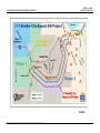


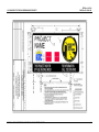


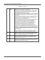


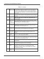
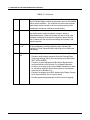
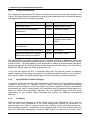


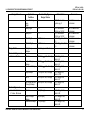
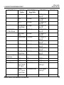
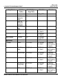


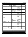


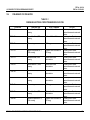


![1127117 - [PROJECT.TOC] - Performance Heating & Plumbing](http://vs1.manualzilla.com/store/data/005895106_1-55e9d6c83dbc31a8ba61d6bb401245cf-150x150.png)