1
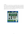
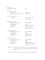
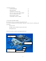
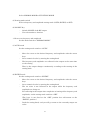
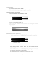
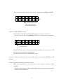
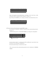
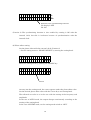
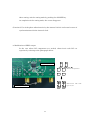
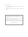
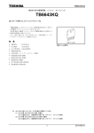
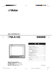
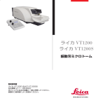
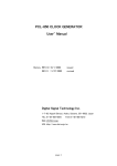
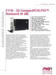
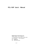
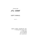
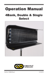
User’s Manual
Model
FIX-3.2GX Control Board
History
rev1.0 2010/08/30 first edition issued
DIGITAL SIGNAL TECHNOLOGY, INC.
1-7-30, Higashi Benzai, Asaka, Saitama, 351-0022, Japan
TEL 81-48-468-6094
FAX 81-48-468-6210
URL: http://www.dst.co.jp/en
1
1. Outline
The FIX-3.2GX is an optional board to set the DDS-PLL synthesizer “DPL-3.2GXF.”
Since it can be mounted over the DPL-3.2GXF, a signal generator included with a
compact controller can be formed. The LCD and encoder on the board enable making of
various settings, such as frequency, amplitude, and RF ON/OFF. Also, the board is
equipped with level converters for CMOS, differential PECL, and differential LVDS,
which are convenient as a logic circuit clock source.
2
2. Specifications
(1) Power supply voltage
5V - 7V
(2) Consumption current
FIX-3.2GX alone:
400mA or less
When connected with DPL-3.2GXF:
1900mA or less
(3) Level converter input level
5 - 3200MHz
Output of DPL-3.2GX is
set at +10dBm.
(4) CMOS level converter
Operating frequency range:
5MHz - 100MHz
Output connector:
BNC
Load impedance:
50Ω load drive possible
Output level:
CMOS (Caution 1)
Switchable by 3V and 5V
(5) LVDS level converter
Operating frequency range:
5MHz - 3200MHz
Output connector:
SMA-J
Load impedance:
Differential 100Ω
Output level:
LVDS (Caution 1)
(6) PECL level converter
Operating frequency range:
5MHz - 3200MHz
Output connector:
SMA-J
Load impedance:
Differential 100Ω
Output level:
PECL (Caution 1) (Caution 2)
Switchable by 3V and 5V
(Caution 1)
Other-than-specified (+10dBm) frequencies and output levels may
cause unstable operation of the LVDS, PECL, and CMOS output
sections.
(Caution 2) The PECL level output sections are DC-cut when factory-shipped.
3
3. Contents of package
(1) FIX-3.2GX body
×1
(2) Coaxial cable
×1
(3) RS232C connection cable
×1
(4) Power supply cable to DPL-3.2GXF
×1
(5) User’s manual (this book)
×1
(6) Screw M2×5 (sems)
×4
(7) Stud M2×5 (male - female)
×4
4. Connection with DPL-3.2GXF
The following cables are attached to the optional board.
If you have purchased the FIX-3.2GXF separately, connect them by following the
procedures.
(1) Power cable
(2) SMA connector (double-ended) coaxial cable
(3) RS-232C cable
Connect the cables as shown in the photograph below.
Power supply cable to the
DPL-3.2GXF
Main body power supply
connector +5V to +7V
Screw
Coaxial cable to be
connected
for
level
conversion
Stud
RS232C connection cable
4
5. Functions
(1) Frequency setting
(2) Amplitude setting
(3) RF output ON/OFF
(4) Saving of frequency and amplitude
(5) Switching of reference signal (internal ⇔ external)
(6) Fine adjustment of internal reference signal
(7) Level conversion of CMOS, PECL, and LVDS
6. Names and functions of keys and switches
Display
表示器
1 0 0 0 0 0 0 0 0 0 . 0 0 0 Hz
O N
I N T
- 1 4 . 5 dBm
Mode switch
モードスイッチ
NORMAL MODE
AUTO
ON/OFF
key
ON/OFFキー
ENTRY
FUNC MODE
RF ON/OFF
設定ノブ
Setting
knob
SET
Setting
mode switch
設定モードスイッチ
←
→
カーソルキー
Cursor
keys
(1) Cursor keys
・
Move the cursor to the desired frequency and amplitude with the cursor
keys.
・
Select the desired item.
(2) Setting knob
・
Set a numerical value for frequency, amplitude, and phase offset.
・
Select the desired menu.
(3) Mode switch
5
Select NORMAL MODE or FUNCTION MODE.
(4) Setting mode switch
Select a frequency and amplitude setting mode (AUTO, ENTRY, or SET).
(5) ON/OFF key
・
Switch ON/OFF of the RF output.
・
Use to determine a function.
7. How to set frequency and amplitude
Set the mode switch to “NORMAL MODE.”
(1) AUTO mode
Set the setting mode switch to “AUTO.”
・
Move the cursor to the desired frequency and amplitude with the cursor
keys.
・
Set a numerical value by turning the setting knob.
・
The frequency and amplitude are reflected in the output at the same time
as the setting.
That is, the output changes continuously according to the turning of the
setting knob.
(2) ENTRY mode
Set the setting mode switch to “ENTRY.”
・
Move the cursor to the desired frequency and amplitude with the cursor
keys.
・
Set a numerical value by turning the setting knob.
・
The set value is not reflected in the output while the frequency and
amplitude are being set.
For reflecting in the output after completion of setting of the frequency and
amplitude, set the setting mode switch to “SET.”
(The lever is not fixed at the “SET” position but self-returns to the
“ENTRY” position.)
・
Push the setting knob, and you will go return to the currently-output set
value.
6
8. Various settings
・
Set the mode switch to “FUNC MODE.”
・
Select the desired setting menu by turning the setting knob.
(1) Saving of frequency and amplitude
The current frequency and amplitude are saved.
S A V E
O N / O F F
K E Y
Execute saving with the ON/OFF key.
When saving ends, “DONE” is displayed. Do not turn off the power until this
display appears.
S A V E
D O N E
(2) Switching of reference signal source
・
Set the setting menu to “CLOCK SOURCE” by turning the setting knob.
C L O C K
S O U R C E
* I N T
E X T
Selection mark
選択マーク
“INT” indicates internal reference signal, and “EXT” indicates external
reference signal.
Set the selection mark “*” to the desired signal by pushing the cursor key(s),
and determine it by pushing the ON/OFF key.
The determined reference signal source is automatically saved.
7
The current reference signal source can be confirmed in “NORMAL MODE.”
1 0 0 0 0 0 0 0 0 0 . 0 0 0 Hz
O N
I N T
- 1 4 . 5 dBm
Reference signal source
基準信号ソース
INT:
internal signal
INT
: 内部信号
EXT
: 外部信号
EXT:
external signal
(3) Power-on RF ON/OFF setting
Set whether to turn ON or OFF the RF output at power-on. (Caution 3)
・ Set the setting menu to “POWER ON RF OUT” by turning the setting knob.
P O W E R
O N
* O N
O F F
R F
O U T
選択マーク
Selection mark
Set the selection mark “*” to the desired side by pushing the cursor key(s), and
determine it by pushing the ON/OFF key.
The determined setting is automatically saved.
(Caution 3) Keep in mind that the current RF output is not turned ON/OFF by this
function.
(4) Fine adjustment of internal reference signal
Make fine adjustment of the frequency of the internal reference signal
(10MHz).
・ Set the setting menu to “INT CLOCK ADJUST” by turning the setting knob,
and push the ON/OFF key.
8
I N T
C L O C K
P U S H
A D J U S T
O N / O F F
K E Y
Since the frequency increases/decreases according to the cursor keys, make
adjustment while checking with the frequency counter, etc.
By pushing the ON/OFF key, the setting is reflected and automatically saved.
< -
U P
D O U N
O N / O F F
K E Y
- >
S A V E
(5) External clock synchronizing function ON/OFF setting
Set whether to turn ON or OFF the external clock synchronizing function.
(Caution 4)
・ Set the setting menu to “CLOCK SYNCHRO” by turning the setting knob.
C L O C K
S Y N C H R O
* O N
O F F
Selection
選択マーク
mark
Set the selection mark “*” to the desired side by pushing the cursor key(s), and
determine it by pushing the ON/OFF key.
The determined setting is automatically saved.
The current state of the synchronizing function can be confirmed in “NORMAL
MODE.”
9
1 0 0 0 0 0 0 0 0 0 . 0 0 0 Hz
O N
I N T
C S
- 1 4 . 5 dBm
External
clock synchronizing function
外部クロック同期機能
(No
display):
(表示無し)
: OFF OFF
CS ON : ON
CS:
(Caution 4) The synchronizing function is also enabled by turning it ON with the
internal clock, but this is irrelevant because of synchronization with the
internal clock.
(6) Phase offset setting
Set the phase offset with the external clock. (Caution 5)
・ Set the setting menu to “PHASE OFFSET” by turning the setting knob.
P H A S E
O F F S T
+ 1 8 0 . 0 D e g
Enter the setting mode by pushing the ON/OFF key.
P H A S E
O F F S T
+ 1 8 0 . 0 D e g
カーソル
Cursor
At entry into the setting mode, the cursor appears under the phase offset value.
Set the desired phase offset value with the cursor keys and setting knob.
The reflected set value is as is the case with the setting of the frequency and
amplitude.
In the case of AUTO mode, the output changes continuously according to the
turning of the setting knob.
In the case of ENTRY mode, set the setting mode switch to “SET.”
10
After setting, exit the setting mode by pushing the ON/OFF key.
At completion of the setting mode, the cursor disappears.
(Caution 5) Use of the phase offset function by the internal clock is irrelevant because of
synchronization with the internal clock.
9. Modification of PECL output
In the case where DC components are needed, short-circuit each DC cut
capacitor by referring to the photograph below.
DC cut capacitors
Remove the capacitors.
Short-circuit with 1608
type 0Ω, etc.
PECL output sections
11
10. Precautions for handling
Use a lower-rippling power supply. When using a switching power supply, use
an appropriate noise filter.
This product is DPL-3.2GXF-specific. Keep in mind that it cannot be used with
DPL-3.2GF.
・ Descriptions in this manual are subject to change without notice.
・ No part of this manual may be reproduced without our permission.
・ We shall assume no liability for any user damage as a result of an
accident, etc.
・ Descriptions in this manual shall not guarantee the practice of industrial
property and other rights or grant a license for them.
・ We shall assume no liability for any third party’s industrial property
rights attributable to the use of circuits, etc., described in this manual.
Digital Signal Technology, Inc.
12