1
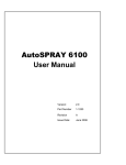
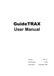
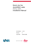
AutoSPRAY
Generic Cable
Installation Manual
Part Number:
Revision
Issue Date:
1-1270
C
April 2008
Copyright Notice
All rights reserved. No part of this publication may be reproduced, stored
in a retrieval system, or transmitted in any form or by any means,
electronic, mechanical photocopying, recording, or otherwise, without the
prior written permission of Rinex Technology.
Disclaimer
No liability is assumed with respect to the use of the information
contained herein. While every precaution has been taken in the
preparation of this publication, RINEX assumes no responsibility for
errors or omissions, nor is any liability assumed for damages resulting
from the use of the information contained herein. Further this publication
and features described herein are subject to change without notice.
Use of this system is strictly limited to providing steering assistance to
the operator who must remain in control of the vehicle at all times.
RINEX, including its officers servants and agents, does not make any
representation to any party and will not accept any responsibility or
liability whatsoever for any loss or damage of whatever nature suffered
by any such person or corporation choosing or seeking to use this
system or any part thereof.
By use of this system you agree that RINEX is not liable or responsible
for any damage whatsoever to the vehicle, any property, personal
injuries, or death that may result from the use or abuse of this system.
AutoSPRAY Generic Cable Installation Manual
Written for RINEX AutoSPRAY controller
Publication Date, July 2005
Copyright © 2005 by Rinex Technology. All rights reserved.
RINEX TECHNOLOGY
ABN: 30 029 441 181
Office Location :
19 Lyall Street
South Perth WA 6151
Postal Address :
PO Box 211
South Perth WA 6951
Telephone :
Local : (08) 9474 4771
International :+61-8-9474 4771
Facsimile :
Local : (08) 9474 4772
International :+61-8-9474 4772
Internet :
http://www.rinex.com.au
Email :
[email protected]
RINEX LIMITED WARRANTY
Products
This warranty covers all products (the “Products”) manufactured and or sold by RINEX Technology
or their authorised dealers.
RINEX Technology Limited Warranty
RINEX Technology (“RINEX”) hereby warrants solely to the end purchaser of the Products, subject
to the exclusions and procedures set forth herein below, that the Products sold to such end
purchaser shall be free, under normal use and maintenance, from defects in material and
workmanship for a period of 12 months from delivery. Repairs and replacement components are
warranted, subject to the exclusions and procedures set forth below, to be free, under normal use
and maintenance, from defects in material and workmanship for 90 days from delivery, or for the
balance of the original warranty period, whichever is greater.
Purchaser’s Exclusive Remedy
The end purchaser’s exclusive remedy under this warranty shall be limited to the repair or
replacement, at the option of RINEX, of any defective Products or components thereof. The end
user shall notify RINEX or a RINEX authorised dealer immediately of any claimed defect. Repairs
shall be made through RINEX only.
Exclusions
RINEX does not warrant damage occurring in transit or due to misuse, abuse, improper
installation, neglect, alteration, abnormal use, lightning (or other electrical discharge), exposure to
moisture or dampness, excessive temperatures, spill of liquids or fluids, or acts of God. Repair,
modification or service of RINEX products by any party other than an authorised RINEX dealer
shall render this warranty null and void. RINEX does not warrant any Product where the Product
serial number or nameplate has been removed, defaced or altered. RINEX does not warrant
claims asserted after the end of the warranty period.
RINEX does not warrant or guarantee the precision or accuracy of positions obtained when using
Products. The potential accuracy of Products as stated in RINEX literature and/or Product
specifications serves to provide only an estimate of achievable accuracy based on:
• Specifications provided by the US Department of Defence for GPS Positioning,
• GPS OEM Receiver specifications of the appropriate manufacturer (if applicable), and
• DGPS service provider performance specifications.
RINEX reserves the right to modify Products without any obligation to notify, supply or install any
improvements or alterations to existing Products.
No Other Warranties
The foregoing warranty is exclusive of all warranties, whether written, oral, implied or arising by
statute, course of dealing or trade usage, in connection with the design, sale, installation, service
or use of any products or any components thereof, including, but not limited to, any warranty of
merchantability or fitness for a particular purpose.
Limitation of Liability
The extent of RINEX’S liability for damages of any nature to the end purchaser or any other person
or entity whether in contract or tort and whether to persons or property shall in no case exceed, in
the aggregate, the cost of correcting the defect in the Product or, at RINEX’S option, the cost of
replacing the defective item. In no event will RINEX be liable for any loss of production, loss of
profits, loss of use for any special, indirect, incidental, consequential or contingent damages, even
if RINEX has been advised of the possibility of such damages. Without limiting the foregoing,
RINEX shall not be liable for any damages of any kind resulting from installation, use, quality,
performance or accuracy of any products.
RINEX LIMITED WARRANTY
Governing Legislation
To the greatest extent possible, this warranty shall be governed by the laws of the State of
Western Australia. In the event that any provision hereof is held to be invalid by a court of
competent jurisdiction, such provision shall be severed from this warranty and the remaining
provisions shall remain in full force and effect.
Obtaining Warranty Service
In order to obtain warranty service, the end purchaser must bring the Product to an authorised
RINEX dealer along with the end purchaser’s proof of purchase. The end purchaser must produce
the original invoice or other purchase documents as proof of the purchase date.
The end purchaser is solely responsible for the cost of transportation of the Product to RINEX or
an authorised RINEX dealer and the Product is at the end purchaser's risk whilst in transit.
For any questions regarding warranty service or to obtain information regarding the location of any
of RINEX’s approved dealers, contact RINEX at the following address:
Rinex Technology
19 Lyall Street
South Perth
Western Australia 6151
Telephone : (08) 9474 4771
Facsimile :
(08) 9474 4772
Internet : www.rinex.com.au
TABLE OF CONTENTS
1
INTRODUCTION ................................................................................................... 1
2
INSTALLATION..................................................................................................... 3
2.1
2.2
2.3
2.4
2.5
Generic installation of the AutoSPRAY cable ...........................................................4
John Deere 4700 with SprayStar controller ..............................................................8
Farmscan 2400 with 2403 section controller ..........................................................11
Micro-Trak 3000 .....................................................................................................14
AgChem Rogator....................................................................................................18
3 TESTING ................................................................................................................. 23
1 INTRODUCTION
The RINEX AutoSPRAY is compatible with a wide variety of spray rate
controllers. RINEX have a range of easy to install interface cables
available for some of the more popular spray rate controllers on the
market. The generic AutoSPRAY cables (P/N 1-2805 & 1-2806) can be
used on almost any compatible spray rate controller or section control
system. A list of known compatible spray rate controllers is shown
below. The limitation is it either will not work or requires additional
hardware for sprayers or controllers where the boom section switches
are tied to ground while the switch is in the OFF position.
The generic AutoSPRAY cable can also be used in place of a controller
specific cable and is therefore compatible with the full range of spray rate
controllers shown below. However it is recommended that a controller
specific cable be used if available.
Most spray rate controllers have a single wire for each section from the
controller to the solenoid or valve on the actual boom spray which
regulates when the section is ON or OFF. Different controllers will have
section switches built into the controller unit, where as others will have
separate or remote switches installed elsewhere in the vehicle for ease
of use.
The RINEX AutoSPRAY works in a similar format to the remote
switches. The AutoSPRAY will energise individual wires for each section
which will open the solenoid or valve for that respective section. When
necessary the sections will be de-energised and the sections will close
accordingly.
The generic AutoSPRAY cable can be used to control up to eight
individual boom sections with PN 1-2805 and thirteen individual boom
sections with PN 1-2806. It is not necessary to use all of the available
sections if not required.
1-1270 Rev B
Generic AutoSPRAY cable installation
Page 1
Compatible spray rate controllers
*
Farmscan 2400 (2403 boom controller)
TeeJet 844
Farmscan 2400 (2405 boom controller*)
TeeJet 844 E
Farmscan 24v1
Raven 4x0 series
John Deere SprayStar
Raven 6x0 series
Mid Tech TASC series
Dickey-John
Mid Tech ARC series
Falcon
There are some variations to these models, check with your local dealer
1-1270 Rev B
Generic AutoSPRAY cable installation
Page 2
2 INSTALLATION
This section describes how to connect and install the generic
AutoSPRAY cable. A schematic of the RINEX AutoSPRAY and spray
rate controller is shown in Figure 2.1.
Figure 2.1 Schematic layout of typical AutoSPRAY
installation
It is recommended that all electrical wiring should be
installed by a qualified auto-electrician. Incorrect wiring
may damage the AutoSPRAY controller and/ or the
spray rate controller.
1-1270 Rev B
Generic AutoSPRAY cable installation
Page 3
2.1
Generic installation of the AutoSPRAY cable
Step
Instruction
1 Determine the number of sections or valves for the spray rate
controller. This is the number of switches on the controller.
Record this in Table 2.2. Note that for eight sections or less use
PN 1-2895 and for nine to thirteen sections use PN 1-2806.
2 Identify the wires that are connected from the solenoid or valves
on the boom spray for each respective section. Record the
colour and/or identification code for each individual section in
Table 2.2. Note that section one is referred to as the left most
section when standing at the rear of the boom spray looking
forward. The section numbers increase towards the right hand
side. Also note that any fence-line or end nozzles should not be
included in these sections.
3 Trace the individual wires for each section through to the
operator’s cabin of the vehicle. Then identify a location where
the generic AutoSPRAY cable can be spliced into the wiring
loom. DO NOT CUT the wires at this point in time.
4 Check that each section wire, as noted in Table 2.2, has +12vDC
when the respective section switch is turned ON. This should be
done using a voltmeter. It is important to check that each section
wire is NOT CONNECTED TO GROUND when the section switch
is turned OFF.
5 Join the matching generic AutoSPRAY cable section wire to the
boom spray section wire as noted in Table 2.2. It is important
that a good reliable connection is made between the two wires. It
is recommended that the connecting wires be soldered together
and insulated accordingly. Any section wire from the generic
AutoSPRAY cable that is not connected should be insulated from
all other wires.
1-1270 Rev B
Generic AutoSPRAY cable installation
Page 4
Step
Instruction
6 To allow the RINEX AutoSPRAY to detect the sprayer master
(run/hold) switch, connect the generic AutoSPRAY cable wire
labelled “master” to the master switch of the sprayer. To insure
the master detect wire is being installed to the right wire use a
volt-meter or a test-light to verify that he RINEX master wire is
connected so that it receives 12Vdc when the master is ON and
0Vdc when the master is OFF.
7 For the Saturn AutoSPRAY connect the RED wire, labelled
POWER to a 12vDC power source that is controlled with the
vehicle ignition wiring (power when the vehicle is ON). Then
connect the BLACK wire to a ground point on the vehicle. For the
AS4080 and AS7500 these connections are not necessary.
8 The spray rate controller should be tested for typical function
before connecting the generic AutoSPRAY cable to the RINEX
AutoSPRAY controller. Subsequent to the test being
successfully completed the generic AutoSPRAY cable should be
connected on the rear panel of the controller as detailed in the
AutoSPRAY installation manual.
Caution:
Power for the AutoSPRAY Controller must be a clean 12vDC
source. Connecting the AutoSPRAY controller to 24vDC will
cause damage to the controller. If connecting to a 24vDC
vehicle 12vDC power must be connected to the same power
source the spray rate controller is using.
1-1270 Rev B
Generic AutoSPRAY cable installation
Page 5
Generic AutoSPRAY Cable
Pin Function
Colour
Label
1 Power
Red
Power
2 Ground
Black
Ground
3 Section 1
Yellow
Section 1
4 Section 2
Grey
Section 2
5 Section 3
Green
Section 3
6 Section 4
Blue
Section 4
7 Section 5
Magenta
Section 5
8 Section 6
Pink
Section 6
9 Section 7
Brown
Section 7
10 Section 8
White
Section 8
11 None
Yellow/Red
Master
Table 2.1
1-1270 Rev B
BoomSpray
Colour
Label
Not connected
1-2805 8 x Section Generic AutoSPRAY cable
Generic AutoSPRAY cable installation
Page 6
BoomSpray
Pin Function
Colour
Colour
3 Section 1
White
Section 1
4 Section 2
White
Section 2
5 Section 3
White
Section 3
6 Section 4
White
Section 4
7 Section 5
White
Section 5
8 Section 6
White
Section 6
9 Section 7
White
Section 7
10 Section 8
White
Section 8
11 None
Yellow/Red
Master
12 Section 9
White
Section 9
13 Section 10 White
Sect 10
14 Section 11 White
Sect 11
15 Section 12 White
Sect 12
16 Section 13 White
Sect 13
Table 2.2
1-1270 Rev B
Label
Not connected
1-2806 13 x section generic AutoSPRAY cable
Generic AutoSPRAY cable installation
Page 7
2.2 John Deere 4700 with SprayStar controller
Step
Instruction
1 Locate the section switch panel on the side console in the John
Deere Self-propelled sprayers as shown in Figure 2.2. Carefully
open the panel the switches are mounted in to prepare for
connecting the AutoSPRAY cable. See Figure 2.3.
2 Identify each section switch number and check the section
number and wire colour match to Table 2.3.
3 Join the matching generic AutoSPRAY cable Table 2.3. It is
important that a good reliable connection is made between the
two wires. It is recommended that the connecting wires be
soldered together and insulated accordingly. The remaining
section wires from the generic AutoSPRAY cable that are not
connected should be insulated from all other wires.
4 Connect the RED wire, labelled POWER to a 12vDC power
source that is controlled with the vehicle ignition wiring (power
when the vehicle is ON). Then connect the BLACK wire to a
ground point on the vehicle.
5 The spray rate controller should be tested for typical function
before connecting the generic AutoSPRAY cable to the RINEX
AutoSPRAY controller. Subsequent to the test being
successfully completed the generic AutoSPRAY cable should be
connected on the rear panel of the controller as detailed in the
AutoSPRAY installation manual.
Caution:
Power for the AutoSPRAY Controller must be a clean 12vDC
source. Connecting the AutoSPRAY controller to 24vDC will
cause damage to the controller. If connecting to a 24vDC
vehicle 12vDC power must be connected to the same power
source the spray rate controller is using.
1-1270 Rev B
Generic AutoSPRAY cable installation
Page 8
Figure 2.2 John Deere Section Switch Panel
Figure 2.3 John Deere Section Switch Wiring
1-1270 Rev B
Generic AutoSPRAY cable installation
Page 9
Generic AutoSPRAY Cable
Pin Function
Colour
John Deere 4700 SprayStar
Label
Colour
1 Power
Red
Power
To be sourced by installer
2 Ground
Black
Ground
To be sourced by installer
3 Section 1
Yellow
Section 1
Blue
4 Section 2
Grey
Section 2
White
5 Section 3
Green
Section 3
Yellow
6 Section 4
Blue
Section 4
Purple
7 Section 5
Magenta
Section 5
Brown
8 Section 6
Pink
Section 6
Not connected
9 Section 7
Brown
Section 7
Not connected
10 Section 8
White
Section 8
Not connected
11 None
Yellow/Red
Master
Not connected
Table 2.3 Generic AutoSPRAY cable connection to John
Deere 4700 SprayStar controller
1-1270 Rev B
Generic AutoSPRAY cable installation
Page 10
2.3 Farmscan 2400 with 2403 section controller
Step
Instruction
1 Identify that the controller is a 2400 Spray rate controller with a
2403 section controller (3 sections). See Figure 2.4. If the 2400
spray rate controller has a 2405 section controller (5
sections), a different cable and installation procedure is
required. Contact you dealer for further information.
2 Locate the Boom Control connector on the rear of the 2400
controller, see Figure 2.5. Identify the 3 boom sections. The valve
wiring may or may not be connected at this point.
3 Join the matching generic AutoSPRAY cable section wire to the
boom spray section wire as noted in Table 2.2. It is important
that a good reliable connection is made between the two wires. It
is recommended that the connecting wires be soldered together
and insulated accordingly. Alternatively the AutoSPRAY section
wires can be screwed into the terminal points on the back of the
2400 controller. The remaining section wires from the generic
AutoSPRAY cable that are not connected should be insulated
from all other wires.
4 Connect the RED wire, labelled POWER to a 12vDC power
source that is controlled with the vehicle ignition wiring (power
when the vehicle is ON). Then connect the BLACK wire to a
ground point on the vehicle.
5 The spray rate controller should be tested for typical function
before connecting the generic AutoSPRAY cable to the RINEX
AutoSPRAY controller. Subsequent to the test being
successfully completed the generic AutoSPRAY cable should be
connected on the rear panel of the controller as detailed in the
AutoSPRAY installation manual.
Caution:
1-1270 Rev B
Power for the AutoSPRAY Controller must be a clean
12vDC source. Connecting the AutoSPRAY controller to
24vDC will cause damage to the controller. If connecting to
a 24vDC vehicle 12vDC power must be connected to the
same power source the spray rate controller is using.
Generic AutoSPRAY cable installation
Page 11
Farmscan 2400 Spray
Controller
2403 Section Controller
(3 Sections only)
2405 Section Controller
(Up to 5 Sections)
Requires different cable
Figure 2.4 Farmscan 2400 spray rate controller identification
Figure 2.5 Farmscan 2400 boom control connector
1-1270 Rev B
Generic AutoSPRAY cable installation
Page 12
Generic AutoSPRAY Cable
Pin Function
Colour
Farmscan 2400
Label
Label
1 Power
Red
Power
To be sourced by installer
2 Ground
Black
Ground
To be sourced by installer
3 Section 1
Yellow
Section 1
Left
4 Section 2
Grey
Section 2
Centre
5 Section 3
Green
Section 3
Right
6 Section 4
Blue
Section 4
Not connected
7 Section 5
Magenta
Section 5
Not connected
8 Section 6
Pink
Section 6
Not connected
9 Section 7
Brown
Section 7
Not connected
10 Section 8
White
Section 8
Not connected
11 None
Yellow/Red
Master
Not connected
Table 2.2 Generic AutoSPRAY cable connection to
Farmscan 2400 Spray controller with 2403 section
controller
1-1270 Rev B
Generic AutoSPRAY cable installation
Page 13
2.4 Micro-Trak 3000
Step
Instruction
1 Identify that the controller is a Micro-Trak 3000 Spray rate
controller. If the spray rate controller is a other than a MicroTrak 3000, a different cable and installation procedure is
required. Contact you dealer for further information.
2 Locate the 15-pin Molex connector on the rear of the 3000
controller, see Figure 2.6. Identify the 3 boom sections. The valve
wiring may or may not be connected at this point.
3 Identify the wires for the 3 boom sections. Use figure 2.7 as a
guide. On some sprayers the wire colors may be different so look
at the pin locations the wires are attached to as well it is advised
to trace the wires to the actual valves or solenoids for verification.
4 Join the matching generic AutoSPRAY cable section wire to the
boom spray section wire as noted in Table 2.4. It is important
that a good reliable connection is made between the two wires. It
is recommended that the connecting wires be soldered together
and insulated accordingly. The remaining section wires from the
generic AutoSPRAY cable that are not connected should be
insulated from all other wires.
5 To allow the RINEX AutoSPRAY to detect the sprayer master
(run/hold) switch, connect the generic AutoSPRAY cable wire
labelled “master” to the run/hold wire on the MT 3000 according
to Table 2.4. To insure the master detect wire is being installed to
the right wire/tab use a volt-meter or a test-light to verify that he
RINEX master wire is connected so that it receives 12Vdc when
the master is ON and 0Vdc when the master is OFF.
6 For Saturn AutoSPRAY installations only, connect the RED wire,
labelled POWER to a 12vDC power source that is controlled with
the vehicle ignition wiring (power when the vehicle is ON). Then
connect the BLACK wire to a ground point on the vehicle. These
steps are not required for AS4080 and AS7500 installations.
1-1270 Rev B
Generic AutoSPRAY cable installation
Page 14
Step
Instruction
7 The spray rate controller should be tested for typical function
before connecting the generic AutoSPRAY cable to the RINEX
AutoSPRAY controller. Subsequent to the test being
successfully completed the generic AutoSPRAY cable should be
connected on the rear panel of the controller as detailed in the
AutoSPRAY installation manual.
Caution:
1-1270 Rev B
Power for the AutoSPRAY Controller must be a clean
12vDC source. Connecting the AutoSPRAY controller to
24vDC will cause damage to the controller. If connecting to
a 24vDC vehicle 12vDC power must be connected to the
same power source the spray rate controller is using.
Generic AutoSPRAY cable installation
Page 15
Figure 2.6
Figure 2.7
1-1270 Rev B
Generic AutoSPRAY cable installation
Page 16
MOLEX Connector Pin-Outs
Pin
Function
Colour
Rinex Color - Label
1 Run/Hold
Red
Yellow/Red - Master
2 Ground
Black
N/A
3 Reserved
Brown
N/A
4 Reserved
White
N/A
5 Flow Input
Red
N/A
6 Boom 3
Black
Green – Section 3
7 Reserved
Unknown
N/A
8 Speed Input Red
N/A
9 Boom 2
White
Grey - Section 2
10 Reserved
Unknown
N/A
11 Reserved
White
N/A
12 Boom 1
Red
Yellow - Section 1
13 Reserved
Unknown
N/A
14 Reserved
Black
N/A
15 Servo Valve Red
N/A
Table 2.4 Typical wiring diagram for Micro-Trak 3000 15-pin
Molex connector
1-1270 Rev B
Generic AutoSPRAY cable installation
Page 17
2.5 AgChem Rogator
This section covers how to use a generic cable (PN 1-2805) to install a RINEX AutoSPRAY
system onto an AgChem Rogator sprayer. For the 12x4 series Rogators, use the 1-2816 and
1-2817 cables that were specifically created for those sprayers.
Step
Instruction
1 Identify that the sprayer is a Rogator with the boom section
switches in a black box in front of the right side arm rest, see
Figure 2.8. If the sprayer is not a Rogator or the boom
switches are different, a different cable and installation
procedure is required. Contact you dealer for further
information.
2 Open the front panel of the switch box to get access the boom
switch wiring, see Figure 2.9.
3 Identify the tab on each switch that is energized when the switch
is ON. This is typically the back tab. Place a spade piggy-back
connector (not supplied) to the tab and replace the original wire
into that tab onto one of the connectors of the piggy-back plug.
See Figure 2.10. Alternatively, the AutoSPRAY section wires can
be spliced into the wire instead of using the piggy-back plugs. If
splicing, this step may be skipped.
4 Join the matching generic AutoSPRAY cable section wire to the
free tab on the piggy-back connector of the appropriate switch. If
no piggy-back is being used, it is recommended that the
connecting wires be soldered together and insulated accordingly.
The remaining section wires from the generic AutoSPRAY cable
that are not connected should be insulated from all other wires.
5 To connect he RINEX AutoSPRAY to detect the sprayer master
switch, connect the generic AutoSPRAY cable wire labelled
“master’ to the input side of any of the section switches. This can
also be done either with a piggy-back plug or it can be
spliced/soldered. To insure the master detect wire is being
installed to the right wire/tab use a volt-meter or a test-light to
verify that he RINEX master wire is connected so that it receives
12Vdc when the master is ON and 0Vdc when the master is OFF.
1-1270 Rev B
Generic AutoSPRAY cable installation
Page 18
Step
Instruction
6 For Saturn AutoSPRAY installations only, connect the RED wire,
labelled POWER to a 12vDC power source that is controlled with
the vehicle ignition wiring (power when the vehicle is ON). Then
connect the BLACK wire to a ground point on the vehicle. These
steps are not required for AS4080 and AS7500 installations.
7 The spray rate controller should be tested for typical function
before connecting the generic AutoSPRAY cable to the RINEX
AutoSPRAY controller. Subsequent to the test being
successfully completed the generic AutoSPRAY cable should be
connected on the rear panel of the controller as detailed in the
AutoSPRAY installation manual.
Caution:
1-1270 Rev B
Power for the AutoSPRAY Controller must be a clean
12vDC source. Connecting the AutoSPRAY controller to
24vDC will cause damage to the controller. If connecting to
a 24vDC vehicle 12vDC power must be connected to the
same power source the spray rate controller is using.
Generic AutoSPRAY cable installation
Page 19
Figure 2.8
1-1270 Rev B
Generic AutoSPRAY cable installation
Page 20
Figure 2.9
1-1270 Rev B
Generic AutoSPRAY cable installation
Page 21
Figure 2.10
1-1270 Rev B
Generic AutoSPRAY cable installation
Page 22
3 TESTING
The test will require that the AutoSPRAY controller be connected with a
GPS receiver and that the spray rig be partially filled with water to
undertake an in-field test. The test will require the spray rig to be in a
field where the boom spray can be operated in a typical manner.
To test the master make sure the AutoSPRAY has been set up for
“external” master control. Refer to the AutoSPRAY users manual on how
to do this. With the power ON in the sprayer and the rate controller
running, watch the master symbol on the RINEX AutoSPRAY unit and
turn the master ON by pressing the master dimmer switch in the cab.
The master symbol on the RINEX AutoSPRAY should show that the
master is now ON. Turn the master OFF again by pressing the dimmer
switch and verify the symbol on the AutoSPRAY reflects that it is now
OFF.
With the master ON and all of the section switches in the OFF position,
run the self-test in the RINEX AutoSPRAY controller. Verify that every
section turns ON and OFF. Also verify that the sections turn ON and
OFF in the proper order. They should cycle from left to right when viewed
from the back of the boom looking forward.
All further testing details can be found in AutoSPRAY User Manual.
1-1270 Rev B
Generic AutoSPRAY cable installation
Page 23