1
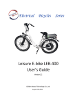
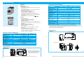
Speed controller
Speed controller
• Standard specification (EX type)
• Features
<MGSD type>
EX type
DV1131
DV1132
Operating voltage range
50/60 Hz
Rated current
Compatible motor output *1
0.4 A
1A
2.0 A
0.3 A
1A
3 to 10 W
15 to 40 W
60 to 0 W
6 to 20 W
25 to 90 W
Operation change
Speed control range
High-response
High-stability
90 to 1400 r/min / 90 to 1700 r/min
50 to 1400 r/min / 50 to 1700 r/min
5% or more
3% or less
Speed variation
Speed setting
From external controller, e.g. external speed changer *3
Active while electric braking current is flowing.
Electric braking time
5 sec typ.
The braking current will be turned off before the 5-sceond limit as the motor stops.
(Braking current is 2 to 3 times the rated current.)
Parallel operation
Enabled
Available (typically up to 5 sec (0 to max. speed))
Soft-start/soft-down capability
Operating temperature range
–10 to 50˚C
Storage temperature
–20 to 60˚C
*1 Applicable to Panasonic compact speed variable geared motors. Select motors with applicable output.
*2 Electric braking has no mechanical brake holding mechanism.
To provide brake holding, use our C&B motor or variable speed motor containing electromagnetic brake.
When braking a load having excessively high inertia, durability and life expectancy of motor shaft and gear should be taken into
consideration. Use the motor within the allowable inertia.
*3 EX type is supplied with the external speed changer.
• Outline drawing
EX type
93.5(3.68)
59(2.32)
50(1.97)
14.2(0.56)
8.0(0.31)
2
8
3
1
ø29(ø1.14)
4(0.16)
3.2(0.13)
48.4(1.9)
6(0.24)
20.8(0.82)
39±0.1
(1.54±0.004)
67.1(2.64)
33(1.3)
4
36(1.42)
Socket (accessory)
5
• Outline drawing
MGSD type
36(1.42)
6
*1 Electric braking has no mechanical holding mechanism.
14.2(0.56)
7
MGSDA1
MGSDB1
MGSDB2
Single phase 100 to 120 VAC
Single phase 200 to 240 VAC
±10% (at rated voltage)
50/60 Hz
1.0 A
2.0 A
1.0 A
3 to 40 W
60 to 90 W
6 to 90 W
50Hz : 90 to 1400 r/min 60Hz : 90 to 1700 r/min
5% : 1000 r/min, Typical variation at 80% rated torque
Internal
Activated while electric braking current is flowing.
0.5 sec (typ.): Amount of braking current is 2 to 3 times the rated current.
Not applicable
80 g
DV1234
Single phase 200 VAC
±10% (at rated voltage)
Power frequency
• Standard specification (MGSD type)
Supply voltage
Supply voltage tolerance
Power frequency
Rated input current
Compatible motor output
Speed control range
Speed regulation (against load)
Speed setting
Braking *1
Electric braking time
Parallel operation
Product weight
DV1231
Index
• Soft-start/soft-down
Time can be adjusted up to 5 seconds.
Excellent soft-start/soft-down linearity.
• Selectable response
High-stable and high-response can be selected with the
internal changeover switch to meet the characteristic of the
application.
(Factory setting: high-response)
• Excellent instantaneous stop capability
• Parallel operation
Two or more motors can be controlled from a single
control knob.
• Can link with various control systems
Can control motor(s) in conjunction with different
controlling systems such as sequencer. The voltage signal
can also be used as control signal.
DV1134
Single phase 100 VAC
Braking*2
<EX type>
EX type
Characteristic
Rated voltage
Options
MGSD type
Part No.
Brake Unit
• Internal speed changer
Motor speed can be adjusted from the speed setting knob
on the front panel.
Not necessary to install and connect an external speed
changer to the controller.
• Electric brake enables instantaneous stop.
• Compact 8P plug-in configuration.
• Variable installation options are available.
Terminal blocks, sockets and other various options
(from Panasonic Electric Works Co.,Ltd.) for panel board
can be used.
• Compliant with international standards:
59(2.32)
ø20(ø0.79)
50(1.97)
t0.8(0.031)
Socket is not supplied with the product.
Use octal pin socket (DV0P4560), option,
or Socket (AW68102) recommended by
Panasonic Electric Works Co.,Ltd.
Unit: mm (inch)
Unit: mm (inch)
* Please read your User's manual carefully so that you will understand the operation and safety precautions before attempting to operate the system.
C-6
* Please read your User's manual carefully so that you will understand the operation and safety precautions before attempting to operate the system.
C-7
MGSD type
• Connection diagram list
Page
Wiring diagram (for unidirectional rotation)
MGSD type
C- 8
Speed change only
MGSD type
C- 9
Unidirectional rotation and electric brake
MGSD type
C-10
C-11
Wiring of cooling fan motor (F) or motor with thermal protector (TP)
MGSD type
C-12
Wiring to electromagnetic brake (40 W or smaller)
MGSD type
C-12
Wiring diagram (for unidirectional rotation)
EX type
C-13
Speed change only
EX type
C-14
Unidirectional rotation and electric brake
EX type
C-15
Normal/reverse rotation and electric brake
EX type
C-16
Multispeed setting application
EX type
C-17
Speed change with analog signal
EX type
C-17
Operation through contactless signal
EX type
C-18
Parallel operation through external speed changer
EX type
C-18
Parallel operation through analog signal
EX type
C-19
Soft-operation
EX type
C-19
Wiring of cooling fan motor (F) and motor with thermal protector (TP)
EX type
C-20
Wiring to electromagnetic brake
EX type
C-20
Panasonic Electric Works Co.,Ltd.
AT7803
Speed control knob
This knob adjusts the rotating speed of the
motor from 90 (r/min) to 1400/1700 (r/min)
at 50/60 Hz.
65
Power supply
100 VAC system: Single phase 100 to 120 VAC
200 VAC system: Single phase 200 to 240 VAC
Ground the return circuit to the earth terminal.
(100 Ω or smaller, ø1.6 mm or more).
43
7 8 1 2
TG
Gray
7
Motor
SW1
3
6
Run
Stop
ON
OFF
Black
Capacitor
Pink
4
TG
Pink
5
Pin No.
NFB
2
1
Rated voltage
input
Spark killer
R1 C1
8
7
CW
3
CCW
6
SW1
White
Gray
SW2
R1 C1
Spark killer
Motor
SW2
Run
Stop
Run
ON
OFF
ON
CW
Black
*
CCW
SW1 : Power switch
SW2 : Normal/reverse selector switch
Capacitor
Pink
TG
Pink
Pin No.
SW1
100 V supply system
5 A or more at 125 VAC
SW2
200 V supply system
5 A or more at 250 VAC
Spark killer R1+C1
DV0P008 (option)
White
Gray
Black
Capacitor cap
Pink
Pink
• National specifications: Option
• Specifications compliant with
overseas standards: Attachment
* In the case of models with a model
number to which “A” is suffixed, the
capacitor cap is optional.
The models with a model number
to which “A” is suffixed
(not equipped with a capacitor
cap) are not sold or available
in Japan.
Ground the return circuit to
the earth terminal.
Capacitor
(100 Ω or less, ø1.6 mm or more). (supplied with the motor)
Tightening torque: 1.0 to 1.5 N·m For connection to the capacitor,
see the motor instruction manual.
* Please read your User's manual carefully so that you will understand the operation and safety precautions before attempting to operate the system.
C-8
White
5
Motor
Power switch
8
4
Noise filter*
Surge absorber*
(option)
CW
SW1
• The motor revolving speed can be set from the speed setting knob on the panel.
• The thick continuous lines represent main circuit. Use conductor of size 0.75 mm2 or larger for the main line.
• The thin continuous lines represent signal circuit. Use conductor of size 0.3 mm2 or larger in the signal circuit.
When the distance from the tachometer generator (TG) is long, use shielded twisted pair cable.
Do not ground the shielding material.
Miniature DIN terminal block
<Precautions>
The input voltage
must be in the
range of rated voltage compatible
with the motor
specification.
*Install a noise filter and surge absorber to protect
against external
noise and lightning surge.
Clockwise
CCW Counterclockwise
Normal/reverse rotation
1 Wiring diagram (for unidirectional rotation)
Circuit breaker (NFB)
: 5A
<Caution>
Install a ground-fault
circuit interrupter in
the power supply.
CW
Rated voltage
input
Index
MGSD type
NFB
SW1
2
1
Options
Normal/reverse rotation and electric brake
Rotating direction viewed
from shaft end
Unidirectional rotation
Speed controller
Speed controller
Brake Unit
1
2
3
4
5
6
7
8
9
10
11
12
13
14
15
16
17
18
2 Speed change only
Function
Speed controller
Connection diagram
Speed controller
Speed controller
<Precautions>
1. To change rotating direction of induction motor:
Provide a motor halt period. Switch over SW2 after complete stop of the motor.
2. To change rotating direction of reversible motor:
A motor halt period is not necessary. Switch over SW2 while keeping SW1 turned ON. When configuring
SW2 with relay contacts, use a relay having large gap between contacts (e.g. HG/HP relay from
Panasonic Electric Works Co.,Ltd.) to prevent malfunction due to short-circuited capacitor.
3. For motors for cooling fan and motors with thermal protector, also refer to page C-12.
4. When using independent relay contacts for SW2 to change over normal/reverse, interlock both contacts
so that they will not close simultaneously.
5. The spark killer consisting of R1 and C1 must be used to protect the relay contacts.
* Please read your User's manual carefully so that you will understand the operation and safety precautions before attempting to operate the system.
C-9
MGSD type
NFB
SW1
2
1
Rated voltage
input
White
Gray
7
8
RUN
SW2
R1
STOP R2
STOP SW3 External
braking
resistor
RUN
Black
Motor
Capacitor
Pink
Pink TG
Braking
Run
5
Pin No.
SW1
SW2
SW3
40 W or larger
7
3
6
4
5
Pin No.
Rated voltage
input
RUN
External
braking
resistor
STOP R2
SW2
Braking
Run
ON
RUN
STOP
RUN
Black
Motor
R1
Capacitor
Spark killer
White
STOP
SW3
RUN
Pink
Pink
TG
7
8
RUN
3
6
4
5
STOP
STOP
Gray
Motor
Black
Capacitor
SW3 RUN
Braking
Pink
Run
TG
Pink
SW1
40 W or larger
SW4
SW5
CW
SW1
2
1
8
CCW
SW4
External
braking resistor CW
RUN STOP R2 CCW
SW5
C1 CW
SW2
R1
Spark killer
7
3
5 A or more at 125 VAC
SW2
200 V supply system
5 A or more at 250 VAC
Pin No.
Stop Reverse
STOP
NFB
Rated voltage
input
Braking
ON
RUN
100 V supply system
DC10 V 10 mA
SW4
CCW
CW
SW5
R2
CCW
External
braking
resistor
C1
R1
SW2
SW1
RUN
CCW
0.7 sec or longer
SW1 : Power switch
SW2 : RUN/STOP switch
SW3 : Braking start switch
SW4 : Normal/reverse selector switch
Gray
Black
Motor
Capacitor
White
STOP
Pink
SW3
RUN
Pink
TG
SW1, SW2 100 V supply system
5 A or more at 125 VAC
SW4, SW5 200 V supply system
5 A or more at 250 VAC
SW3
DC10 V 10m A
Spark killer R1+C1
DV0P008 (option)
Spark killer R1+C1
DV0P008 (option)
External braking resistor R2
DV0P003 (option)
External braking resistor R2
DV0P003 (option)
<Precautions>
1. When SW2 and SW3 are switched from RUN to STOP, electric braking is applied for approx. 0.5 sec, and
the motor stops instantly.
Difference in switching time between SW2 and SW3 must be 0.1 sec or shorter. If SW2 (SW3) is in RUN
position while SW3 (SW2) is in STOP, abnormal operation occurs (full speed rotation for a short time) and
motor temperature rises excessively.
2. The number of start/stop operations must be 6/min. or less.
3. For motors for cooling fan and motors with thermal protector, also refer to page C-12.
4. The spark killer consisting of R1 and C1 must be used to protect the relay contacts.
5. R2 limits flow of discharging current upon short-circuiting of the capacitor during braking.
* Please read your User's manual carefully so that you will understand the operation and safety precautions before attempting to operate the system.
C-10
White
6
4
5
SW3
Clockwise
CCW Counterclockwise
CW
Spark killer
CW
C1
CW
Rated voltage
input
SW2
SW3
SW1 : Power switch
SW2 : RUN/STOP switch
SW3 : Brake start switch
Gray
NFB
Pin No.
Speed controller
Speed controller
2
1
8
NFB
SW1
Stop
SW1
2
1
Index
3
6
4
Spark killer
C1
Rotating direction viewed
from shaft end
25 W or smaller
Options
Speed controller
CW
• Connection according to this wiring
diagram causes the motor to rotate
clockwise when viewed from the
motor shaft end. To run the motor
counterclockwise, interchange the
connecting point of black and gray
leads.
Brake Unit
25 W or smaller
4 Normal/reverse rotation and electric brake
Speed controller
3 Unidirectional rotation and electric brake
Speed controller
Speed controller
<Precautions>
1. When SW2 and SW3 are switched from RUN to STOP, electric braking is applied for approx. 0.5 sec,
and the motor stops instantly. (Do not operate SW4 and SW5 until the motor stops.)
Difference in switching time between SW2 and SW3 must be 0.1 sec or smaller. If SW2 (SW3) is in RUN
position while SW3 (SW2) is in STOP, abnormal operation occurs (full speed rotation for a short time)
and motor temperature rises excessively.
2. Do not change the motor rotating direction (SW4, SW5) while the motor is running.
3. The number of start/stop operations must be 6/min. or less.
4. For motors for cooling fan and motors with thermal protector, also refer to page C-12.
5. The spark killer consisting of R1 and C1 must be used to protect the relay contacts.
* Please read your User's manual carefully so that you will understand the operation and safety precautions before attempting to operate the system.
C-11
MGSD type
1
Pin No.
SW A
Ry
Closed
SWB
TP Blue
TP
Closed Closed
Closed
SWA
SW B
TP Blue
Ry
External speed changer (VR)
Opened
Closed
ON
ON
ON
• Soft-start/down control
F(Black)
F(Black)
TP
F
Ry Relay
TG
Closed
Run
Reset
NFB
TG(Pink)
Relay
Ry
SW A
Momentary N.O. contact
SW B
Momentary N.C. contact
100 V supply system
125 VAC 5 A or more 3a contact
200 V supply system
250 VAC 5 A or more 3a contact
<Precautions>
1. The thermal protector (TP) is an automatic reset type. To prevent hazards caused by restarting, connect
the TP as shown above. Don’t connect TP directly to the power supply.
2. Once the TP operates, cooling period is required before the operation can restart.
3. Connect the cooling fan motor (F) across pins 1 and 2 on the power terminal.
4. Motor (M) and tachometer generator (TG) should be connected according to corresponding wiring
diagram shown later.
6 Wiring to electromagnetic brake (40 W or smaller)
Speed controller
• Variable speed motor with electromagnetic
brake should be wired as shown below.
SW1
2
1
Pin No.
NFB
Rated voltage
input
C1
STOP RUN
SW9
Motor
Yellow
Yellow
Brake
SW1
100 V supply system
5 A or more at 125 VAC
SW9
200 V supply system
5 A or more at 250 VAC
Spark killer R1+C1
DV0P008 (option)
(supplied with the controller)
Soft-start and soft-down times can
be adjusted by a single setting.
Use this feature to protect the load
from shock caused by sharp speed
change at startup and shutdown of
the motor.
To disable the soft operation, turn
the control fully clockwise.
Power
supply
Circuit breaker (NFB)
: 5A
<Caution>
Install a ground-fault
circuit interrupter in
the power supply.
6
• Maximum speed control
Use this control to adjust the
revolving speed when the external
speed changer is set at the top
speed.
Adjust the speed to 1400 (r/min) or
below at 50 Hz; or 1700 (r/min) or
below at 60 Hz.
5
4
3
Index
Rated voltage
input
Ry
R1
Spark killer
Used to set the number
of revolutions.
1/4 W, 20 kΩ, taper B
Closed
Options
Black
M White
Gray
7 Wiring diagram (for unidirectional rotation)
• The thick continuous lines represent main circuit. Use conductor of size 0.75 mm2 or larger for the main line.
• The thin continuous lines represent signal circuit. Use conductor of size 0.3 mm2 or larger in the signal circuit.
When the distance from the tachometer generator (TG) is long, use shielded twisted pair cable.
Ry
2
EX type
Brake Unit
Speed controller
5 Wiring of cooling fan motor (F) or motor with thermal protector (TP)
Speed controller
Speed controller
Speed controller
DIN terminal block
AT7803
Panasonic Electric
Works Co.,Ltd.
(extra-cost option)
Power switch
(extra-cost option)
• Operation changeover switch
Select “high-stable” or “highresponse”:
<High-stable>
• Keeps the rotation speed variation TG
low against variation in load.
• Enables a wide range of speed
control.
• Suitable for capability control.
• May fail to maintain constant
rotation speed upon sharp load
change.
<High-response>
• Enables quick response with low
CW
hunting.
• Suitable for positioning
application.
Motor
• May fail to keep rotation speed
variation low against variation in
load.
• Not suitable for controlling wide
range of speed.
7
8 1 2
White
Gray
Pink
Black
Pink
Capacitor
(supplied with motor)
Ground the return circuit to the earth terminal.
(100 Ω or less, ø1.6 mm or more).
Tightening torque: 1.0 to 1.5 N·m
<Precautions>
1. Operate SW9 simultaneously with RUN/STOP switching of other switches, if any.
Placing other switch to RUN position while the brake is active (SW9 at STOP position) causes the motor
to generate heat.
2. For remaining wirings, refer to corresponding wiring diagram.
* Please read your User's manual carefully so that you will understand the operation and safety precautions before attempting to operate the system.
C-12
* Please read your User's manual carefully so that you will understand the operation and safety precautions before attempting to operate the system.
C-13
EX type
8 Speed change only
9 Unidirectional rotation and electric brake
Normal/reverse rotation
NFB
Speed controller
Gray
Black
Motor
8
3
3
6
Capacitor
2
VR
Pink
VR
1
5
4
Pink
TG
Pink
Pink TG
SW2 200 V supply system
ON
R1+C1
Normal
SW1
Reverse
• With the external speed changer connected,
the motor can be started/stopped with a small
signal through SW6 contact while the power
switch SW1 (see diagram above) is on. The
SW6 provides shorter start-up time than SW1.
3
3
6
SW6 2
VR
RUN
5
4
STOP
1
External speed changer
(DVOP002)
1/4 W, 20 kW, taper B
DC10V 10mA
To TG
Pin No.
<Precautions>
1. Power (SW1) should be turned on at least 0.5
sec before turning on of the start signal (SW6).
2. When the motor is not operated for a
prolonged time, turn off power switch (SW1).
5 A or more at 250 VAC
DV0P008 (option)
5 A or more at 250 VAC
SW3
3
VR
RUN
Pink
Pink
DC10 V 10 mA
R1+C1
DV0P008 (option)
R2
DV0P003 (option)
TG
1
40 W or larger
CW
SW1
NFB
Operation from maximum speed control
• When no external speed changer is required,
the speed can be adjusted from the
maximum speed control.
3
6
R3 20 kΩ 1/4 W
To TG
Pin No.
<Precautions>
1. Connect a fixed resistor (R3) in place of
external speed changer (VR).
Braking
Rated voltage
input
CCW
SW1 : Power switch
SW2 : Normal/reverse selector switch
5
4
SW2 200 V supply system
2
SW3
2
1
* Please read your User's manual carefully so that you will understand the operation and safety precautions before attempting to operate the system.
C-14
STOP
RUN
5 A or more at 125 VAC
SW2
5 A or more at 125 VAC
STOP
RUN
<Precautions>
1. To change rotating direction of induction motor:
Provide a motor halt period. Switch over SW2 after complete stop of the motor.
2. To change rotating direction of reversible motor:
A motor halt period is not necessary. Switch over SW2 while keeping SW1 turned ON. When configuring
SW2 with relay contacts, use a relay having large gap between contacts (e.g. HG/HP relay from
Panasonic Electric Works Co.,Ltd.) to prevent malfunction due to short-circuited capacitor.
3. For motors for cooling fan and motors with thermal protector, also refer to page C-20.
4. When using independent relay contacts for SW2 to change over normal/reverse, interlock both contacts so
that they will not close simultaneously.
5. The spark killer consisting of R1 and C1 must be used to protect the relay contacts.
Start/stop control with small signal
R2
3
SW1 100 V supply system
Capacitor
Pin No.
CW
Black
8
Stop
Run
Gray
Speed controller
Stop
Run
Motor
R1
SW2
5
4
This wiring diagram causes the motor to rotate clockwise
when viewed from the motor shaft end.
To run the motor counterclockwise, interchange the
connecting point of black and gray leads.
SW1 100 V supply system
8
Black
C1
STOP
RUN
6
Pin No.
Pin No.
SW1
Motor
Gray
7
Index
1
5
4
Black
Capacitor
3
CW
White
Gray
SW2
CCW
R1
C1
2
Rated voltage
input
White
CW
7
8
3
6
C1
• Connection according to this wiring
diagram causes the motor to rotate
clockwise when viewed from the
motor shaft end. To run the motor
counterclockwise, interchange the
connecting point of black and gray
leads.
NFB
Options
Speed controller
White
7
Rated voltage
input
R1
CW
SW1
2
1
NFB
SW1
2
1
Rated voltage
input
Speed controller
SW1
2
1
25 W or smaller
Brake Unit
Unidirectional rotation
Speed controller
Speed controller
SW1
RUN
STOP
R1
Capacitor
C1
6
5
4
STOP SW3
3
VR
Pink
Pink
RUN
RUN
SW1 : Power switch
SW2 : RUN/STOP switch
SW3 : Brake start switch
2
RUN
STOP
SW2
SW3
White
7
3
Motor
Run
ON
R2
SW2
Braking
TG
1
Pin No.
<Precautions>
1. When SW2 and SW3 are switched from RUN to
STOP, electric braking is applied for approx. 5
sec, or until the motor stops.
SW2 and SW3 must be operated
simultaneously. Otherwise, abnormal operation
occurs (full speed rotation for a short time),
causing the motor temperature rises
excessively.
2. The number of start/stop cycles must be 6/min.
or less.
3. When using cooling fan motor or motor with
thermal protector, also see page C-20.
4. Insert R1 and C1 to protect relay contact.
5. R2 restricts discharge current in case of
capacitor short circuit during braking.
Operation from maximum speed control
• When no external speed changer is required,
the speed can be adjusted from the maximum
speed control.
3
6
STOP
SW3
RUN
R3 20 kΩ 1/4 W
5
4
To TG
Pin No.
<Precautions>
1. Connect a fixed resistor (R3) in place of
external speed changer (VR).
* Please read your User's manual carefully so that you will understand the operation and safety precautions before attempting to operate the system.
C-15
EX type
10 Normal/reverse rotation and electric brake
11 Multispeed setting application
No braking applied
STOP SW3
Rated voltage
input
Rotating direction viewed
from shaft end
CW
SW4
White
CCW
STOP
RUN
CCW Counterclockwise
Gray
R1
SW2
Motor
Black
CW
SW5
R2
STOP
6
SW4, SW5 200 V supply system 5 A or more at 250 VAC
Capacitor
3
SW3
SW1, SW2 100 V supply system 5 A or more at 125 VAC
SW3
2
VR
RUN
Pink
TG
Pink
1
5
4
DC10 V 10 mA
R1+C1
DV0P008 (option)
R2
DV0P003 (option)
Gray
SW4
VR2
1
VR3
1
2
Pin No.
1
VR2
SW3, SW8
3
2
VR1
2
VR3
1
DC10V 10 mA
VR1
DV0P002
VR2
1
(option)
VR3
5
4
To TG
To TG
Pin No.
R2
8
Black
CCW
CW
SW2
RUN
R1
STOP
C1
SW5
Capacitor
CCW
Motor
Stop Reverse
Normal
SW1
ON
SW2
SW3
STOP
SW4
SW5
RUN
RUN
CW
CCW
White
7
STOP
3
SW3
VR
RUN
No braking applied
Braking
SW1
Pink
Pink
TG
SW1 : Power switch
SW2 : RUN/STOP switch
SW3 : Braking start switch
SW4,SW5 : Normal/reverse selector switch
1
Pin No.
<Precautions>
1. When SW2 and SW3 are switched from RUN to
STOP, electric braking is applied for approx. 5
sec, or until the motor stops. (Do not operate
SW4 and SW5 until the motor stops completely.)
SW2 and SW3 must be operated simultaneously.
Otherwise, abnormal operation occurs (full speed
rotation for a short time), causing the motor
temperature rises excessively.
2. Do not change the rotating direction (SW4, SW5)
while the motor is running.
3. The number of start/stop cycles must be 6/min.
or less.
4. When using cooling fan motor or motor with
thermal protector, also see page C-20.
5. Insert R1 and C1 to protect relay contact.
6. R2 restricts discharge current in case of
capacitor short circuit during braking.
Operation from maximum speed control
• When no external speed changer is required,
the speed can be adjusted from the maximum
speed control.
Speed controller
Speed controller
1
5
4
NFB
Rated voltage
input
CW
3
6
STOP
Rated voltage
input
MAX
DC5V
6
GND
5
4
To TG
Pin No.
Braking applied
SW1
2
1
3
NFB
Rated voltage
input
STOP SW7
6
MAX
DC5V
GND
RUN
5
4
To TG
6
5
4
5 A or more at 125 VAC
200 V supply system
5 A or more at 250 VAC
To TG
Pin No.
<Precautions>
1. Connect a fixed resistor (R3) in place of
external speed changer (VR).
DC10 V 10 mA
GND
R1
1 kΩ
emax
(r/min)
1700
1400
R2
1000
To TG
0
emax
3
– 1 kΩ
emax : Analog signal max. voltage
500
Pin No.
100 V supply system
SW7
5
R2
3
Pin No.
SW1
RUN
R3 20 kΩ 1/4 W
4
NFB
2
1
3
<Precautions>
1. Turn on power switch SW1 approx. 0.5 sec earlier than the
analog start signal.
2. For repetitive run/stop operations, use the analog signal while
keeping SW1 ON.
3. Soft-operation can be adjusted from the soft-start and softdown controls or by using analog signal.
4. On the maximum speed control, set the maximum motor
revolving speed that may be achieved at the maximum analog
signal value (e.g. 3 VDC).
5. The absolute maximum rating of analog signal is 5 VDC.
The system should be designed to use standard 3 VDC analog
signal. If the signal voltage exceeds 3 VDC, the circuit diagram
shown below should be used for wiring.
SW3
* Please read your User's manual carefully so that you will understand the operation and safety precautions before attempting to operate the system.
C-16
2
2
VR1
3
3
<Precautions>
1. Set external speed changers VR1, VR2 and VR3 to 3 different speeds and select the desired speed from
SW8.
2. When activating the brake, simultaneously switch over SW3 and RUN-STOP of other switches.
3. For remaining wirings, refer to the corresponding wiring diagrams.
Speed controller
SW1
2
1
5
4
2
Speed controller
Braking
40 W or larger
6
3
3
3
SW8
RUN
6
12 Speed change with analog signal
Pin No.
3
SW8
6
Index
3
CCW
Speed controller
8
C1
Clockwise
3
Options
Speed controller
CW
Speed controller
3
Speed controller
2
1
7
Braking applied
NFB
SW1
Brake Unit
25 W or smaller
Speed controller
Speed controller
1
2
3 (V)
R1 : External resistor: 1 kΩ
R2 : External resistor
Analog signal (DC)
6. Revolution speed “0” signal should not exceed 0.1 VDC.
7. The input speed pattern (curve) may not be exactly
reflected on the motor speed, due to inertial effect of the
load, especially during stop sequence.
8. The percentage ripple of analog voltage signal should be
2% or less.
9. For other wirings, refer to the corresponding circuit/wiring
diagrams.
10. When using the braking feature, motor wiring (pins 1, 7
and 8) should be in accordance with pages C-8 and C-9.
To activate braking, switch SW2 and SW7 at the same
time.
If SW2 is in RUN position while SW7 is in STOP,
abnormal operation occurs (full speed rotation for a short
time); or if SW7 is in RUN position while SW2 is in
STOP, motor temperature rises excessively.
* Please read your User's manual carefully so that you will understand the operation and safety precautions before attempting to operate the system.
C-17
EX type
15 Parallel operation through analog signal
Braking applied
Tr
STOP
1
RUN
5
4
Pin No.
To TG
Internal equivalent circuit
3
6
VR
1
Tr
RUN
STOP
5
4
To TG
Pin No.
3
6
MAX
DC5V
3
1 kΩ
6.2 V
1 μF
RUN
Tr
STOP
22 kΩ
GND
5
4
6
To TG
1 μF
5
Speed controller
Speed controller
1
3
6
5
4
Pin No.
3
6
5
4
Pin No.
To TG
Pin No.
To TG
Index
2
VR
5
4
16 Soft-operation
To TG
<Precautions>
1. Power switch SW1 should be turned on approx. 0.5
sec before the operation start signal from SW6.
2. When repeating run/stop cycles, turn on/off only SW6
while keeping SW1 turned ON. In this way, the motor
can be controlled by using a small signal. To stop
operation for a long time, also turn off SW1.
3. Soft-start/soft-down period is the time required for the
equipment to start up from stop state to full speed
when the external speed changer is set at maximum
value.
4. Soft-start/soft-down control, when at the full
clockwise position, disables the soft-down function.
As the stop signal is input, power supply to the motor
is turned off immediately. However, the revolving
speed gradually decreases in proportion to the inertia
of the load and motor starts free-running stop
sequence.
5. Soft-start/soft-down control can set maximum time
length of approx. 5 seconds (Typ. at FCCW). The
setting may be exceeded if the inertia of the load is
too large.
6. For other electrical connections, refer to
corresponding circuit/wiring diagrams.
Electrical wirings are the same as for “Unidirectional
rotation and electric brake” and “Normal/reverse
rotation and electric brake”.
Adjust the soft-start time from the soft-start/down
control.
* Please read your User's manual carefully so that you will understand the operation and safety precautions before attempting to operate the system.
NFB
SW1
• Soft-start, soft-down
3
3
6
To TG
• Soft-start and electric brake
C-18
5
4
Pin No.
14 Parallel operation through external speed changer
<Precautions>
1. The resistance Rs of the external speed changer
VR should be as follows:
Rs = 20/N (kΩ)
where, N is the number of motors.
2. For synchronous operation or ratio operation,
desired revolving speeds must be set from the
maximum speed control.
Soft-start and soft-down controls and operation
changeover switch must be set to the same
position.
3. Wirings from the external speed changer VR should
be connected to the same pins (No.5 and 6) on the
controller.
4. Malfunction may occur as the number of devices
operated in parallel increases.
To secure correct operation, connect a noise filter
to each unit.
5. For other electrical connections, refer to
corresponding circuit/wiring diagrams.
3
6
Pin No.
1 kΩ
2
1
Speed controller
VR
2
Speed controller
2
Speed controller
3
6
Analog signal and brake
3
Options
Speed controller
3
DC
0 to +3 V
GND
Brake Unit
No braking applied
<Precautions>
The input impedance of the controller is approx. 100 kΩ.
The output impedance of the analog signal source
should be determined based on the total input
impedance of the speed controllers.
Speed controller
• Small signal relays SW3, SW6 and SW7 can be replaced with transistor.
Speed controller
13 Operation through contactless signal
Speed controller
Speed controller
Rated voltage
input
To motor
3
6
2
RUN
3
VR
DOWN
1
SW6
5
4
To TG
Pin No.
SW1
100 V supply system
5 A or more at 125 VAC
200 V supply system
5 A or more at 250 VAC
SW6
DC10 V 10 mA
Soft-start
Soft-down
Speed
SW1
SW6
ON
RUN
0.5 sec or more
* Please read your User's manual carefully so that you will understand the operation and safety precautions before attempting to operate the system.
C-19
EX type
Speed controller
48 mm sq. (1.89 inchsq.) type
• Features
Ry
Closed
1
Closed Closed
Closed
SW A
SW A
Ry
2
Pin No.
Black
M White
Gray
F(Black)
F(Black)
TP Blue
TP
SW B
Opened
Closed
Ry
ON
Closed
ON
ON
Reset
SW B
TP
TP Blue
Closed
Run
NFB
Ry
Rated voltage
input
F
SD48 type
TG
TG(Pink)
Options
• First DIN 48 size in the industry
Compact space saving model (control panel)
(standardized panel machining holes)
A wide choice of options (recommended by Panasonic
Electric Works Co.,Ltd.)
• Simplified and neat wiring arrangement
Main circuit and signal inputs are isolated on the terminal
block.
Use of 8-pin terminal block requires fewer wiring
connections.
• Can operate under a wide range of power supply voltage
(100V 100 to 120V, 200V 200 to 240V)
Brake Unit
Speed controller
17 Wiring of cooling fan motor and motor with thermal protector
Speed controller
Speed controller
EX48 type
Index
Ry
SW A
Momentary N.O. contact
SW B
Momentary N.C. contact
100 V supply system
125 VAC 5 A or more 3a contact
200 V supply system
250 VAC 5 A or more 3a contact
Ry
<Precautions>
1. The thermal protector (TP) is an automatic reset type. To prevent hazards caused by restarting, connect the
TP as shown above. Don't connect TP directly to the power supply.
2. Once the TP operates, cooling period is required before the operation can restart.
3. Connect the cooling fan motor (F) across pins 1 and 2 on the power terminal.
4. Motor (M) and tachometer generator (TG) should be connected according to corresponding wiring diagram
shown later.
• Standard specification
SD48 type
Part No.
18 Wiring to electromagnetic brake
DVSD
48AL
DVSD
48BL
DVSD
48CL
EX48 type
DVSD
48AY
DVSD
48BY
DVSD
48CY
DVEX
48AL
DVEX
48BL
DVEX
48CL
DVEX
48AY
DVEX
48BY
DVEX
48CY
Characteristic
Speed controller
• Variable speed motor with electromagnetic brake should be wired as shown below.
SW1
Rated voltage
NFB
2
1
Rated voltage
input
Pin No.
R1
SW9
RUN
STOP
Yellow
Yellow
Motor
Brake
SW1
100 V supply system
5 A or more at 125 VAC
SW9
200 V supply system
5 A or more at 250 VAC
R1+C1
200 to 240 VAC
200 to 240 VAC
±10% (at rated voltage)
Power frequency
50/60Hz
50/60 Hz
Compatible motor
output *1
Speed variation
0.5 A
1.0 A
2.0 A
0.3 A
0.5 A
1.0 A
Speed setting
Brake *3
Parallel operation
Soft-start/down
0.5 A
1.0 A
2.0 A
0.3 A
0.5 A
1.0 A
3 to 20 W 25 to 40 W 60 to 90 W 3 to 20 W 25 to 40 W 60 to 90 W 3 to 20 W 25 to 40 W 60 to 90 W 3 to 20 W 25 to 40 W 60 to 90 W
90 to 1400 r/min / 90 to 1700 r/min
DV0P008 (option)
<Precautions>
1. SW9 should be switched to RUN or STOP at the same time as the other switches are switched to RUN or
STOP.
If the other switches are set to RUN while the brake is energized (SW9 in STOP position), the motor will
generate heat.
2. For other wirings, refer to the corresponding circuit/wiring diagrams.
If the application is speed change without using electric braking (page C-14), perform wiring according to
“Start/stop control with small signal”.
100 to 120 VAC
±10% (at rated voltage)
Rated current
C1
100 to 120 VAC
Operating voltage
range
Internal
Mode A (high-response mode) : 50 to 1400 r/min / 50 to 1700 r/min
Mode B (high-response mode) : 90 to 1400 r/min / 90 to 1700 r/min
*2
External speed changer, analog voltage,
maximum speed setting control
Applies braking force to the motor by feeding electric
braking current to the motor for 0.5 sec (typ)
Applies braking force to the motor by feeding electric
braking current to the motor for 5 sec (typ)
(Turns off electric braking current even within 5 sec as the motor stops.)
Not possible
Possible
Not applicable
Variable up to 5 sec (typ) (0 to max. revolving speed)
Operating
temperature range
–10 to 50˚C
–10 to 50˚C
Storage temperature
–20 to 60˚C
–20 to 60˚C
*1. Applicable to Panasonic compact geared motors and variable speed motors.
*2. EX48 models are set to mode A (high-stable) upon shipment.
*3. Electric braking has no mechanical brake holding force.
To provide the holding force, use a variable speed motor with electromagnetic braking feature.
* Please read your User's manual carefully so that you will understand the operation and safety precautions before attempting to operate the system.
C-20
* Please read your User's manual carefully so that you will understand the operation and safety precautions before attempting to operate the system.
C-21