1
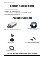
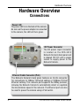
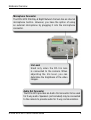
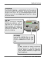
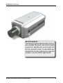
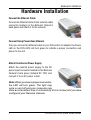
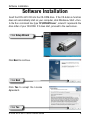
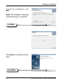
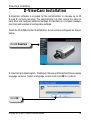
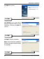
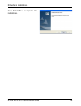
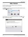
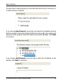
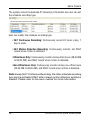
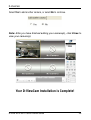
System Requirements
System Requirements
• Internet Explorer 6.x or above
• Windows® XP or Windows Vista™
• 1.7GHz processor or better and at least 256MB of RAM
• An available Ethernet connection
Package Contents
DCS-3410
POE Day & Night Network Camera
Camera Stand
CD-ROM with Manual and
Setup Wizard
12V 1.25A AC Power Adapter
CAT5 Ethernet Cable
If any of the above items are missing, please contact your reseller.
D-Link DCS-3410 Quick Install Guide
Hardware Overview
Hardware Overview
Connections
Power LED
The power LED is on the back of the camera.
As soon as the power adapter is connected
to the camera, the LED will turn green.
DC Power Connector
The DC power input connector
is located on the DCS-3410
Network Camera’s back panel and
is labeled 12V DC with a single
socket to supply power to the
Network Camera.
Ethernet Cable Connector (PoE)
The Network Camera’s back panel features an RJ-45 connector
for connections to 10Base-T Ethernet cabling or 100Base-TX Fast
Ethernet cabling. This network port supports the NWay protocol,
allowing the Network Camera to automatically detect or negotiate
the transmission speed of the network. The Ethernet port can also
be used to power the camera using a PoE switch.
D-Link DCS-3410 Quick Install Guide
Hardware Overview
Microphone Connector
The DCS-3410 PoE Day & Night Network Camera has an internal
microphone built-in. However, you have the option of using
an external microphone by plugging it into the microphone
connector.
Iris Level
Used only when the DC-Iris lens
is connected to the camera. When
adjusting the Iris level, you can
determine the brightness of the video
images.
Audio Out Connector
The DCS-3410 provides an Audio Out connector to be used
for 2-way audio. Speakers (not included) may be connected
to the camera to provide audio for 2-way communication.
D-Link DCS-3410 Quick Install Guide
Hardware Overview
I/O Connector
The DCS-3410 provides a terminal block with three pairs of
connectors situated on the back panel. Two pairs are for input and
the other is for output. The I/O connectors provide the physical
interface to send and receive digital signals to and from a variety
of external devices.
Link LED
Once a connection has been
established via Ethernet port, the
LINK LED will turn solid green. If
traffic is passing to the camera the
LINK LED will blink. If no ethernet
connection is detected, the LINK
LED will not light up.
Reset Button
Reset will be initiated when the reset
button is pressed once and held until
the Power LED flashes through its cycle
twice.
BNC
The BNC connector is used for professional
video connections. It benefits users who
integrate digital IP camera into traditional
system (CCTV) for both analog and digital video
streaming purpose.
D-Link DCS-3410 Quick Install Guide
Hardware Overview
DC-Iris Connector
The Camera supports additional DC-Iris lens,
and provides the power and control signal
required for adjusting the lens through this
DC-Iris connector (4-pin). You can attach any
standard DC-Iris lens (optional) for a specific
purpose, such as outdoor applications.
D-Link DCS-3410 Quick Install Guide
Hardware Installation
Hardware Installation
Connect the Ethernet Cable
Connect an Ethernet cable to the network cable
connector located on the Network Camera’s
back panel and attach it to the network.
Connect Using Power-Over-Ethernet
Once you connect an Ethernet cable to your PoE switch or adapter, the Power
LED on the DCS-3410 will turn green to indicate a proper connection and
power to the unit.
Attach the External Power Supply
Attach the external power supply to the DC
power input connector located on the Network
Camera’s back panel (labeled DC 12V) and
connect it to an AC power outlet.
Note: When you have a proper connection,
the LED will turn green. The light may
cycle on and off and your computer may
show an intermittent loss of connectivity, this is normal until you have
configured your Network Camera.
D-Link DCS-3410 Quick Install Guide
Software Installation
Software Installation
Insert the DCS-3410 CD into the CD-ROM drive. If the CD Autorun function
does not automatically start on your computer, click Windows® Start > Run.
In the Run command box type “D:\DCS3410.exe”, where D: represents the
drive letter of your CD-ROM. If it does start, proceed to the next screen.
Click Setup Wizard
Click Next to continue.
Click Next
Click Yes to accept the License
Agreement.
Click Yes
D-Link DCS-3410 Quick Install Guide
Software Installation
To start the installation, click
Next.
Note: The installation may take
several minutes to complete.
Click Next
Click Finish to complete the installation.
Click Finish
D-Link DCS-3410 Quick Install Guide
Configuration
Configuring Your Camera with
the Setup Wizard
Click on the D-Link Setup Wizard SE icon that was created in your Windows
Start menu.
Click D-Link Setup Wizard SE
The Setup Wizard will appear and show the MAC address of the DCS-3410
and an IP Address (which may or may not be correct depending on what
you have your DCS-3410 connected to). If you have a DHCP server on your
network, there will be a valid IP Address displayed here.
Note: A DHCP server is a device that supplies the same IP address.
Click the Wizard button
D-Link DCS-3410 Quick Install Guide
10
Configuration
Enter the admin ID and password.
Note: The default Admin ID is admin
with the password left blank.
Click Next
Select DHCP if you want to obtain a new IP
address every time the camera boots up.
Click Next
Select static IP to use the same IP address
at each boot up.
Click Next
11
D-Link DCS-3410 Quick Install Guide
Configuration
Click Restart
Viewing Your Network Camera
Click the button labeled Link to access the web configuration. The Setup
Wizard will automatically open your web browser to the IP address of the
DCS-3410, in this example it is: http://192.198.0.120. Your DCS-3410 may
have a different IP Address.
Click Link
D-Link DCS-3410 Quick Install Guide
12
Configuration
Enter admin as the default username and leave the password blank. Click
OK to continue.
This section shows your camera’s live video. You can select your video profile
and other options; such as Snapshot, Recording, etc. For more information
on using the web configuration, please refer to the user manual.
13
D-Link DCS-3410 Quick Install Guide
DViewCam Installation
D-ViewCam Installation
D-ViewCam software is included for the administrator to manage up to 32
D-Link IP cameras remotely. The administrator can also record the video to
hard drive and configure advanced settings. D-ViewCam is a complete management tool and includes all configurative settings.
Insert the CD-ROM into the CD-ROM drive. A menu screen will appear as shown
below.
Click D-ViewCam
D-ViewCam provides English, Traditional Chinese and Simplified Chinese setup
language versions. Select a language version and click OK to continue.
Click OK
D-Link DCS-3410 Quick Install Guide
14
DViewCam Installation
Click Next to continue.
Click Next
Click Browse if you would like to
choose a specific folder for the
installation, otherwise click Next to
continue.
Click Next
Click Next to start the installation.
Note: The D-ViewCam installation
process may take several minutes
to complete.
Click Next
15
D-Link DCS-3410 Quick Install Guide
DViewCam Installation
Click Finish to complete the
installation.
D-Link DCS-3410 Quick Install Guide
16
Add a Camera
Add a Camera
To start D-ViewCam, click on Windows® Start > All Programs >
D-Link > D-Link D-ViewCam.
Use Admin as the default user name and leave the password blank. Click the
(Check
Box) to continue.
The D-ViewCam screen will appear as shown below. Click (Next)
begin the Add Camera wizard.
17
to
D-Link DCS-3410 Quick Install Guide
Add a Camera
Choose either to add camera(s) by automatically searching for camera(s) or
to add camera(s) manually.
If you choose Auto Discovery, the system will search all available cameras
that are located in the same subnet within the same LAN. The system will
place all found cameras under the default map called My Map. Click Next
to continue.
If you choose Add Manually, you will need to enter the IP address of the
camera. Click Next to continue.
D-Link DCS-3410 Quick Install Guide
18
Add a Camera
The system shows the detected IP Camera(s) information and user can set
the schedule recording type.
User can modify the schedule recording type:
• 24/7 Continuous Recording: Continuously record 24 hours a day, 7
days a week.
• 24/7 Motion Detection Recording: Continuously monitor, but ONLY
record when motion is detected.
• Office Hours Only: Continuously monitor during office hours (08:00 AM
to 06.00 PM), and ONLY record when motion is detected.
• Non-Office Hours Only: Continuously monitor during non-office hours
(06:00 PM to 08.00 AM), and ONLY record when motion is detected.
Note: Except 24/7 Continuous Recording, the other schedule recording
type can be activated ONLY when image motion detection window is
created. Please refer to the users manual for more information.
19
D-Link DCS-3410 Quick Install Guide
D-ViewCam
Select Yes to add another camera, or select No to continue.
Note: After you have finished adding your camera(s), click Close to
view your camera(s).
Your D-ViewCam Installation is Complete!
D-Link DCS-3410 Quick Install Guide
20
Notes
Notes
21
D-Link DCS-3410 Quick Install Guide
Notes
Notes
D-Link DCS-3410 Quick Install Guide
22
Notes
Notes
23
D-Link DCS-3410 Quick Install Guide
Technical Support
D-Link’s website contains the latest user documentation and software
updates for D-Link products.
U.S. and Canadian customers can contact D-Link Technical Support
through our website or by phone.
United States
Telephone
(877) 453-5465
World Wide Web
http://support.dlink.com
Canada
Telephone
(800) 361-5265
World Wide Web
http://support.dlink.com
Version 1.0
May 9, 2008
6ICS3410Q.01G
Copyright ©2008 D-Link Corporation/D-Link Systems, Inc. All rights reserved. D-Link and the D-Link logo are registered
trademarks of D-Link Corporation or its subsidiaries in the United States and other countries. Other trademarks are the property
of their respective owners. Actual data throughput will vary. Network conditions and environmental factors, including volume
of network traffic, building materials and construction, and network overhead lower actual data throughput rate. Product
specifications, size and shape are subject to change without notice, and actual product appearance may differ from that depicted
on the packaging. Visit www.dlink.com for more details.
D-Link DCS-3410 Quick Install Guide
24