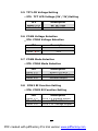
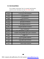
1
FIR-650 Series
INTEL Processor
Embedded Board
With Ethernet, USB 2.0, Audio
User’s Manual
Version 1.2
January,14, 2005
PDF created with pdfFactory Pro trial version www.pdffactory.com
Contents
1.
Introduction .............................................. 4
1.1 Specifications ...................................................5
1.2 What You Have.................................................7
2.
Installation ................................................ 8
2.1 FIR-C650’S Layout ...........................................8
2.2 FIR-C650’s Dimension (Unit: mm)..................10
2.3 Unpacking Precautions ...................................11
2.4 Clear CMOS Setup...........................................11
2.5 TFT LCD Voltage Setting .................................12
2.6 COM4 Voltage Selection..................................12
2.7 COM4 Mode Selection .....................................12
2.8 COM2 RI Function Setting...............................12
2.9 COM1 RI Function Setting...............................13
3. Connection............................................ 14
3.1 LVDS Connector..............................................15
3.2 VGA Connector ...............................................15
3.3 LAN Connectors ..............................................16
3.4 USB Port Connectors ......................................16
3.5 Serial Ports.....................................................17
1
PDF created with pdfFactory Pro trial version www.pdffactory.com
3.6 Keyboard/Mouse Connectors..........................18
3.7 Audio Connectors ...........................................18
3.8 Parallel Port ...................................................19
3.9 PCI E-IDE Disk Drive Connector......................20
3.10 Compact Flash Storage Card Socket ...............21
3.11 Power Button Connector.................................22
3.12 Power LED Connector .....................................22
3.13 Digital I/O Connector .....................................22
3.14 +12V DC Power Connector .............................22
3.15 Power LED and Power button connector.........23
3.16 LCD Back Light connector ...............................23
3.17 Multi-function connector ................................23
3.18 Power output connector .................................24
4. AMI BIOS Setup................................... 25
4.1 Introduction ...................................................25
4.2 Starting Setup ................................................25
4.3 Using Setup ....................................................26
4.4 Getting Help ...................................................27
4.5 Main Menu ......................................................27
4.6 Standard CMOS Setup.....................................30
4.7 Advanced CMOS Setup....................................31
4.8 Advanced Chipset Setup .................................36
2
PDF created with pdfFactory Pro trial version www.pdffactory.com
4.9 Power Management Setup ..............................38
4.10 PCI / Plug and Play Setup ..............................40
4.11 Peripheral Setup............................................42
4.12 Hardware Monitor Setup.................................44
4.13 Change Supervisor Password .........................44
Appendix A: Watchdog Timer ................. 46
Appendix B: I/O Address Map ................ 48
Appendix C: How to use Wake-Up ......... 50
Appendix D: Digital I/O ........................... 51
3
PDF created with pdfFactory Pro trial version www.pdffactory.com
1. Introduction
Thank you for choosing FIR-C650 embedded board.
FIR-C650 is a factor CPU board equipped with a low
power consumption and high performance VIA EDEN
processor. It is designed for system manufacturers,
integrators, or VARs who want to provide quality and
reliable CPU board at a reasonable price.
FIR-C650 has a built-in the ProSavage4 AGP4X VGA
controller. It is a 2D/3D graphics controller, which
provides resolution up to 1920x1440, and supports
both CRT and LCD. The VGA controller can share 832MB frame buffer of system memory.
For applications requiring a high-speed serial
transmission, FIR-C650 provides both USB 1.1 and USB
2.0. The high speed USB 2.0 host controller
implements an ECHI interface that provides 480Mb/s
bandwidth.
Both on-chip UARTs are compatible with the NS16C550.
The parallel port and IDE interface are compatible with
IBM PC/AT architecture.
FIR-C650 also has a built-in 10/100 Fast Ethernet LAN,
which is a fully integrated 10BASE-T/100BASE-TX LAN
controller with high performance and low power
consumption features.
FIR-C650 uses the advanced VIA VT8606/VT82C686B
Chipsets, which is 100% software compatible chipset
with PCI 2.2 standard.
4
PDF created with pdfFactory Pro trial version www.pdffactory.com
1.1 Specifications
CPU
DMA channels
Interrupt levels
Chipset
RTC
Main memory
Ultra DMA 100
IDE interface
Serial ports
Bi-directional
parallel port
Hardware monitor
USB 2.0/1.1 port
Watchdog timer
INTEL processor
7
15
VT8606
VT82C686B
One 144-pin SODIMM socket supports
133Mhz SDRAM. The maximum
memory is up to 512MB.
Up to four PCI Enhanced IDE hard
drives are supported. The Ultra DMA
100 IDE can handle data transfer up
to 100MB/s. Compatible with existing
ATA IDE specifications is the best
advantage, so there is no need to do
any changes for users’ current
accessories.
Four RS-232 ports with 16C550 UART
(or compatible) with 16-byte FIFO
buffer. Support up to 115.2Kbps.
The ports can be individually
configured to COM1, COM2, COM3,
COM4 or disabled.
Configurable to LPT1, LPT2, LPT3 or
disabled. Supports EPP/ECP/SPP.
Built-in to monitor power supply
voltage and fan speed status.
Supports 4 USB2.0 and 1 USB1.1
ports for future expansion.
Software programmable, reset
5
PDF created with pdfFactory Pro trial version www.pdffactory.com
VGA controller
Ethernet
Keyboard and
PS/2 mouse
Audio
Compact flash
Power
generated when watchdog timer is
time-out. Can use I/O Port hex
043(843) & 443 to control the
watchdog.
Built-in ProSavage4 AGP4X 256-bit
2D/3D graphics engine. 8-32MB
share Memory. Screen Resolution: up
to 1920x1440.
Fast Ethernet controllers, IEEE 802.3u
Auto-Negotiation supports 10BASET/100BASE-TX standard. The RJ45
connectors are located on the
mounting bracket for easy connection.
A 6-pin mini DIN connector is located
on the mounting bracket for easy
connection to a keyboard or PS/2
mouse. For alternative application, a
keyboard and a PS/2 mouse pin
header connector are also available
on board.
AC’97 Audio CODEC
It can be used with a passive adapter
(True IDE Mode) in a Type I/II
Socket.
+12V @ 2.5A (max).
consumption
Operating
0°-60° C
temperature
6
PDF created with pdfFactory Pro trial version www.pdffactory.com
1.2 What You Have
FIR-C650’s package includes the following items:
User Manual x1.
FIR-C650 Embedded Board x1.
6-pin Mini-Din converts to two 6-pin mini-Din cables for
keyboard and mouse connection x1.
Driver CD x1.
If any of these items is missing or damaged, contact
the dealer from whom you purchased this product.
Save the shipping materials and carton in case you
want to ship or store the product in the future.
7
PDF created with pdfFactory Pro trial version www.pdffactory.com
2. Installation
This chapter describes how to install FIR-C650. Follow
the unpacking information carefully and refer to the
following diagram of FIR-C650 when necessary.
2.1 FIR-C650’S Layout
8
PDF created with pdfFactory Pro trial version www.pdffactory.com
9
PDF created with pdfFactory Pro trial version www.pdffactory.com
2.2 FIR-C650’s Dimension (Unit: mm)
10
PDF created with pdfFactory Pro trial version www.pdffactory.com
2.3 Unpacking Precautions
Some components of FIR-C650 are very sensitive
to static electricity and can be damaged by a
sudden rush of power. To protect it from
unintended damage, be sure to follow these
precautions:
•
Ground yourself to remove any static charge
before touching FIR-C650. You can do it by
using a wrist strap connected to the ground or
by frequently touching any conducting
materials connected to the ground.
•
Handle your FIR-C650 by its edges. Do not
touch IC chips, leads or circuitry.
•
Do not plug any connector or jumper when the
power is on.
2.4 Clear CMOS Setup
To clear the CMOS Setup (for example, if you have
forgotten the password, you should clear the CMOS
and then re-set the password), you have to close the
JP1 (2-3) for about 3 seconds, and then open it. This
will put the system back to normal operation mode.
• JP1: Clear CMOS Setup
JP1
1-2
(default)*
Short 2-3
Description
Keep CMOS Setup
(Normal Operation)
Clear CMOS Setup
*Note: All shaded rows in the tables of this manual
are the default settings for the FIR-C650.
11
PDF created with pdfFactory Pro trial version www.pdffactory.com
2.5 TFT LCD Voltage Setting
• JP3: TFT LCD Voltage (5V / 3V) Setting
JP3
Short 1–2
Short 2–3
Description
3V TFT LCD
5V TFT LCD
2.6 COM4 Voltage Selection
• JP4: COM4 Voltage Selection
JP4
Short 1-2
Short 3-4
Description
+12V
+5V
2.7 COM4 Mode Selection
• JP5: COM4 Mode Selection
JP5
Short 1-2
Short 3-5
Short 4-6
2.8
Description
Short CTS-RTS
+12 or +5V output
Ground output
COM2 RI Function Setting
• JP6: COM2 RI Function Setting
JP6
Short 1-2
Short 3-4
Short 5-6
Description
RI is +5 Voltage output
RI function
RI is +12 Voltage output
12
PDF created with pdfFactory Pro trial version www.pdffactory.com
2.9
COM1 RI Function Setting
• JP7: COM1 RI Function Setting
JP7
Short 1-2
Short 3-4
Short 5-6
Description
RI is +5 Voltage output
RI function
RI is +12 Voltage output
13
PDF created with pdfFactory Pro trial version www.pdffactory.com
3. Connection
This chapter describes how to connect peripherals,
switches and indicators to the FIR-C650 board.
Label
LVDS1
VGA1
VGA2
LAN1
LAN2
USB1
USB2
COM1
COM2
COM4
KB_MS1
KB1
SPK_OUT1
MIC_IN1
LPT1
IDE1
CF1
PS_ON1
LED1
CN1
CN2
CN3
CN4
CN5
CN6
CN7
Function
LVDS LCD Panel connector
VGA connector
VGA connector
LAN RJ45 connector
LAN connector
USB dual port connector
USB port connector
Serial port connectors
Serial port connectors
Serial port connectors
Keyboard & Mouse connector
Internal Keyboard connector
Speaker out connector
MIC in connector
Parallel port connector
Ultra ATA100 Primary IDE connectors
Compact Flash Storage Card Type II connector
Power on Switch
Power LED
Digital I/O connector
+12V DC power connector
Power LED and Power button connector
LVDS back light connector
Multi-function connector
Line out connector
Power output connector
14
PDF created with pdfFactory Pro trial version www.pdffactory.com
3.1
LVDS Connector
FIR-C650 can support 1 channel (18 or 24bit) LVDS
panel, which can be connected to LVDS1. The pin
assignments are as follows.
• LVDS1: LVDS LCD Connector
PIN
Description
PIN
Description
1
LCD Vcc (+3V or +5V)
2
LCD Vcc (+3V or +5V)
3
LVDS data0 4
LVDS data0 +
5
GROUND
6
GROUND
7
LVDS data1 8
LVDS data1 +
9
GROUND
10
GROUND
11
LVDS data2 12
LVDS data2 +
13
GROUND
14
GROUND
15
LVDS clock 16
LVDS clock +
17
GROUND
18
GROUND
19
LVDS data3 20
LVDS data3 +
3.2
VGA Connector
• VGA1: 15-pin Female Connector
PIN
Description
PIN
1
RED
2
3
BLUE
4
5
GROUND
6
7
GROUND
8
9
VCC / NC
10
11
NC
12
13
HSYNC
14
15
DDC_CLK
• VGA2: 10-pin male Connector
PIN
Description
PIN
1
RED
6
2
GREEN
7
3
BLUE
8
4
HSYNC
9
5
VSYNC
10
Description
GREEN
NC
GROUND
GROUND
GROUND
DDC_DAT
VSYNC
Description
DDC_DAT
DDC_CLK
GROUND
GROUND
GROUND
15
PDF created with pdfFactory Pro trial version www.pdffactory.com
3.3
LAN Connectors
FIR-C650 is equipped with two 10/100Mbps Ethernet
controllers, which are connected to the LAN via
RJ45 connectors. The pin assignments are as follows.
• LAN1: RJ45 Connector (10/100M)
PIN
1
2
3
4
5
6
Description
TX+
TXRX+
N/C
N/C
RX-
PIN
7
8
9
10
11
12
Description
N/C
N/C
Speed +
Speed Active/LINK +
Active/LINK -
• LAN2: LAN Connector (10/100M)
PIN
1
3
5
3.4
Description
TX+
TXRXC
PIN
2
4
6
Description
TXC
RX+
RX-
USB Port Connectors
The FIR-C650 is equipped with two USB (Version.2.0)
ports and one USB (Version.1.1) port for the future
new I/O bus expansion.
• USB1: 2 ports USB Connector (USB2.0)
PIN
1
2
3
4
Description
VCC
DATA0DATA0+
GROUND
PIN
5
6
7
8
Description
VCC
DATA1DATA1+
GROUND
16
PDF created with pdfFactory Pro trial version www.pdffactory.com
• USB2: USB Connector (USB1.1)
PIN
1
3
Description
VCC
DATA+
PIN
2
4
Description
DATAGROUND
3.5 Serial Ports
The FIR-C650 offers three high-speed NS16C550
compatible UART with 16-byte Read/Receive FIFO
serial ports.
• COM1: D-SUB Serial Port Connector
PIN
Description
PIN
Description
1
DCD
6
DSR
2
RXD
7
RTS
3
TXD
8
CTS
4
DTR
9
RI
5
GROUND
• COM2: D-SUB Serial Port Connector
PIN
Description
PIN
Description
1
DCD
6
DSR
2
RXD
7
RTS
3
TXD
8
CTS
4
DTR
9
RI
5
GROUND
• COM4: RJ45 Serial Port Connector
PIN
Description
PIN
Description
1
+12/+5V
2
+12/+5V or CTS
3
GROUND
4
GROUND or RTS
5
DTR
6
DSR
7
TXD
8
RXD
17
PDF created with pdfFactory Pro trial version www.pdffactory.com
3.6
Keyboard/Mouse Connectors
FIR-C650 has a 6-pin DIN keyboard/mouse
connector and a 5-pin keyboard connector.
• KB_MS1: Mini-DIN Keyboard/Mouse
Connector
PIN
1
2
3
4
5
6
Description
KEYBOARD DATA
MOUSE DATA
GROUND
+5V
KEYBOARD CLOCK
MOUSE CLOCK
• KB1: 6-pin Keyboard Connector
PIN
Description
1
+5V
2
KEYBOARD CLOCK
3
PC KB CLOCK
4
KEYBOARD DATA
5
PC KB DATA
6
GROUND
3.7 Audio Connectors
The onboard AC’97 CODEC supports several audio
functions. The audio connectors are described
below.
• SPK_OUT1: Speaker out connector
PIN
1
3
5
Description
NC
Line Out (Left)
NC
PIN
2
4
6
Description
GROUND
Speaker Out (Right)
NC
18
PDF created with pdfFactory Pro trial version www.pdffactory.com
• MIC_IN1: MIC-in connector
PIN
1
3
5
Description
NC
MIC In
NC
PIN
2
4
6
Description
GROUND
NC
NC
• CN6: Line-out connector
(1W/Channel)
PIN
1
3
Description
LINE Out (Left)
LINE Out (Right)
PIN
2
4
Description
GROUND
GROUND
3.8 Parallel Port
Usually, a printer is connected to the parallel port.
FIR-C650 includes an on-board parallel port,
accessed via a 26-pin flat-cable.
• LPT1: Parallel Port Connector
PIN
1
2
3
4
5
6
7
8
9
10
11
12
13
Description
STROBE#
DATA 0
DATA 1
DATA 2
DATA 3
DATA 4
DATA 5
DATA 6
DATA 7
ACKNOWLEDGE
BUSY
PAPER EMPTY
LPT SELECT
PIN
14
15
16
17
18
19
20
21
22
23
24
25
26
Description
AUTO FORM FEED#
ERROR#
INITIALIZE
LPT SELECT LN#
GROUND
GROUND
GROUND
GROUND
GROUND
GROUND
GROUND
GROUND
NC
19
PDF created with pdfFactory Pro trial version www.pdffactory.com
3.9 PCI E-IDE Disk Drive Connector
You can attach up to four IDE (Integrated Device
Electronics) devices.
• IDE1: IDE Interface Connector
PIN
1
3
5
7
9
11
13
15
17
19
21
23
25
27
29
31
33
35
37
39
41
43
Description
RESET#
DATA 7
DATA 6
DATA 5
DATA 4
DATA 3
DATA 2
DATA 1
DATA 0
GROUND
DRQ
IOW#
IOR#
CHRDY
DACK
INTERRUPT
SA1
SA0
HDC CS0#
HDD ACTIVE#
+5V
GND
PIN
2
4
6
8
10
12
14
16
18
20
22
24
26
28
30
32
34
36
38
40
42
44
Description
GROUND
DATA 8
DATA 9
DATA 10
DATA 11
DATA 12
DATA 13
DATA 14
DATA 15
N/C
GROUND
GROUND
GROUND
REV. PULL LOW
GROUND
N/C
PD66 SELECT
SA2
HDC CS1#
GROUND
+5V
N/C
20
PDF created with pdfFactory Pro trial version www.pdffactory.com
3.10 Compact Flash Storage Card Socket
The FIR-C650 configures Compact Flash Storage Card
in IDE Mode. This type II Socket is compatible with IBM
Micro Drive.
• CF1: Compact Flash Storage Card Socket pin
assignment
PIN
1
2
3
4
5
6
7
8
9
10
11
12
13
14
15
16
17
18
19
20
21
22
23
24
25
Description
GROUND
D3
D4
D5
D6
D7
CS1#
N/C
GROUND
N/C
N/C
N/C
VCC
N/C
N/C
N/C
N/C
A2
A1
A0
D0
D1
D2
N/C
PULL DOWN
PIN
26
27
28
29
30
31
32
33
34
35
36
37
38
39
40
41
42
43
44
45
46
47
48
49
50
Description
PULL DOWN
D11
D12
D13
D14
D15
CS3#
N/C
IOR#
IOW#
VCC
IRQ15
VCC
MASTER/SLAVE
N/C
RESET#
IORDY
N/C
VCC
ACTIVE#
PDIAG#
D8
D9
D10
GROUND
21
PDF created with pdfFactory Pro trial version www.pdffactory.com
3.11 Power Button Connector
• PS_ON1: Power Button Connector
PIN
1
3
Description
GROUND
GROUND
PIN
2
4
Description
PS_ON
GROUND
3.12 Power LED Connector
• LED1: Power LED Connector
PIN
1
3
Description
+5V
+5V Standby
PIN
2
Description
GROUND
3.13 Digital I/O Connector
• CN1: Digital I/O Connector
PIN
1
3
5
3.14
Description
GROUND
DI/O IN0
DI/O OUT1
PIN
2
4
6
Description
DI/O OUT0
+12V
GROUND
+12V DC Power Connector
FIR-C650 is equipped with one power connector.
• CN2: +12V DC Power Connector
PIN
1
3
Description
+12V
+12V
PIN
2
4
Description
GROUND
GROUND
22
PDF created with pdfFactory Pro trial version www.pdffactory.com
3.15
Power LED and Power button connector
•CN3: IDE LED and Reset connector
PIN
1
3
3.16
Description
Power_on LED+
GROUND
PIN
2
4
Description
Power_off LED+
Power_on button
LCD Back Light connector
•CN4: LCD Back Light connector
PIN
Description
1
+12V
3
GROUND
5
Back Light enable
3.17
PIN
2
4
Description
+12V
GROUND
Multi-function connector
•CN5: Multi-function connector (USB2.0 and COM3)
PIN
1
3
5
7
9
11
13
Description
+5V
USBUSB+
GROUND
DTR
RTS
RX
PIN
2
4
6
8
10
12
14
Description
+5V
USBUSB+
GROUND
CTS
TX
DSR
23
PDF created with pdfFactory Pro trial version www.pdffactory.com
3.18
Power output connector
Supply power for extension use.
•CN7: Power output connector
PIN
1
3
Description
+5V
GROUND
PIN
2
4
Description
GROUND
+12V
24
PDF created with pdfFactory Pro trial version www.pdffactory.com
4. AMI BIOS Setup
4.1 Introduction
This manual discusses AMI Setup program built
into the ROM BIOS. The Setup program allows
users to modify the basic system configuration.
This special information is then stored in batterybacked CMOS RAM so that it retains the Setup
information when the power is turned off.
4.2 Starting Setup
The AMI BIOS is immediately activated when you
first power on the computer. The BIOS reads the
system information contained in the CMOS and
begins the process of checking out the system and
configuring it. When it finishes, the BIOS will seek
an operating system on one of the disks and then
launch and turn control over to the operating
system.
While the BIOS is in control, the Setup program
can be activated in one of two ways:
1. By pressing <Del> immediately after switching
the system on, or
2. by pressing the <Del>key when the following
message appears briefly at the bottom of the
screen during the POST.
Press DEL to enter SETUP.
If the message disappears before you respond and
you still wish to enter Setup, restart the system to
try again by turning it OFF then ON or pressing the
"RESET" button on the system case. You may also
restart by simultaneously pressing <Ctrl>, <Alt>,
and <Delete> keys. If you do not press the keys
at the correct time and the system does not boot,
25
PDF created with pdfFactory Pro trial version www.pdffactory.com
an error message will be displayed and you will
again be asked to...
PRESS F2 TO CONTINUE, DEL TO ENTER SETUP
4.3 Using Setup
In general, you use the arrow keys to highlight items,
press <Enter> to select, use the PageUp and
PageDown keys to change entries, press <F1> for help
and press <Esc> to quit. The following table provides
more detail about how to navigate in the Setup
program using the keyboard.
Up arrow
Down
arrow
Left arrow
Right arrow
Esc key
PgUp key
PgDn key
+ key
- key
F1 key
F2 /F3 key
F4 key
F5 key
F6 key
F7 key
F8 key
F9 key
F10 key
Move to previous item
Move to next item
Move to the item in the left hand
Move to the item in the right hand
Main Menu -- Quit and not save changes into
CMOS
Status Page Setup Menu and Option Page Setup
Menu -- Exit current page and return to Main Menu
Increase the numeric value or make changes
Decrease the numeric value or make changes
Increase the numeric value or make changes
Decrease the numeric value or make changes
General help, only for Status Page Setup Menu and
Option Page Setup Menu
Change color from total 16 colors. F2 to select
color forward, (Shift) F2 to select color backward
Reserved
Reserved
Reserved
Reserved
Reserved
Reserved
Save all the CMOS changes, only for Main Menu
26
PDF created with pdfFactory Pro trial version www.pdffactory.com
4.4 Getting Help
Press F1 to pop up a small help window that
describes the appropriate keys to use and the
possible selections for the highlighted item. To
exit the Help Window press <Esc> or the F1 key
again.
If, after making and saving system changes with
Setup, you discover that your computer no longer
is able to boot, the AMI BIOS supports an override
to the CMOS settings which resets your system to
its defaults.
The best advice is to only alter settings which you
thoroughly understand. To this end, we strongly
recommend that you avoid making any changes to
the chipset defaults. These defaults have been
carefully chosen by both AMI and your systems
manufacturer to provide the absolute maximum
performance and reliability. Even a seemingly
small change to the chipset setup has the potential
for causing you to use the override.
4.5 Main Menu
Once you enter the AMIBIOS™ CMOS Setup Utility,
the Main Menu will appear on the screen. The
Main Menu allows you to select from several setup
functions and two exit choices. Use the arrow
keys to select among the items and press <Enter>
to accept and enter the sub-menu.
27
PDF created with pdfFactory Pro trial version www.pdffactory.com
Note that a brief description of each highlighted
selection appears at the bottom of the screen.
The main menu includes the following main setup
categories. Some systems may not include all
entries.
Field
Description
Standard CMOS
Setup
Use this menu for basic system
configuration.
Advanced CMOS
Setup
Use this menu to set the Advanced
Features available on your system.
Advanced Chipset
Setup
Use this menu to change the values
in the chipset registers and optimize
your system's performance.
Power Management
Setup
When Disabled, SMI will not be
initialized, and complete power
management functionality is
removed until this option is set to
28
PDF created with pdfFactory Pro trial version www.pdffactory.com
Enabled.
PCI / Plug and Play
Setup
This entry appears if your system
supports PnP / PCI.
Peripheral Setup
Use this menu to specify your
settings for integrated peripherals.
Hardware Monitor
Setup
Use this menu to monitor your
hardware.
Auto-detect Hard
Disks
Use this menu to specify your
settings for hard disks control.
Change Supervisor
Password
Use this menu to set User and
Supervisor Passwords.
Auto Configuration
with Optimal
Settings
Use this menu to load the BIOS
default values that are factory
settings for optimal performance
system operations. While AMI has
designed the custom BIOS to
maximize performance, the factory
has the right to change these
defaults to meet their needs.
Auto Configuration
with Fail-Safe
Settings
Use this menu to load the BIOS
default values for the
minimal/stable performance for
your system to operate.
Save Settings and
Exit
Save CMOS value changes to CMOS
and exit setup.
Exit Without Saving
Abandon all CMOS value changes
and exit setup.
29
PDF created with pdfFactory Pro trial version www.pdffactory.com
4.6 Standard CMOS Setup
The items in Standard CMOS Setup Menu are
divided into 10 categories. Each category includes
no, one or more than one setup items. Use the
arrow keys to highlight the item and then use the
<PgUp> or <PgDn> keys to select the value you
want in each item.
Main Menu Selections
Item
Date
Time
IDE
Primary Master
IDE
Primary Slave
IDE
Secondary
Master
Options
MM DD YYYY
HH : MM : SS
Options are in its sub
menu (described in
Table 3)
Options are in its sub
menu
(described in Table 3)
Options are in its sub
menu
(described in Table 3)
Description
Set the system date
Set the system time
Press <Enter> to
enter the sub menu of
detailed options
Press <Enter> to
enter the sub menu of
detailed options
Press <Enter> to
enter the sub menu of
detailed options
30
PDF created with pdfFactory Pro trial version www.pdffactory.com
IDE
Secondary
Master
Drive A
Drive B
Halt On
Base Memory
Extended
Memory
Options are in its sub
menu
(described in Table 3)
None
360K, 5.25 in
1.2M, 5.25 in
720K, 3.5 in
1.44M, 3.5 in
2.88M, 3.5 in
All Errors
No Errors
All, but Keyboard
All, but Diskette
All, but Disk/Key
N/A
N/A
Press <Enter> to
enter the sub menu of
detailed options
Select the type of
floppy disk drive
installed in your
system
Select the situation in
which you want the
BIOS to stop the POST
process and notify you
Displays the amount
of conventional
memory detected
during boot up
Displays the amount
of extended memory
detected during boot
up
4.7 Advanced CMOS Setup
This section allows you to configure your system
for basic operation. You have the opportunity to
select the system’s default speed, boot-up
sequence, keyboard operation, shadowing and
security.
31
PDF created with pdfFactory Pro trial version www.pdffactory.com
Quick Boot
When set to enabled, DRAM testing function will
disable.
1st /2nd /3rd Boot Device
This option sets the type of device for the first boot
drives that the AMIBIOS attempts to boot from after
AMIBIOS POST completes. The settings are Disabled,
IDE-0, IDE-1, IDE-2, IDE-3, Floppy, ARMD-FDD, ARMDHDD, CDROM, SCSI.
Try Other Boot Devices
Set this option to Yes to instruct AMIBIOS to attempt to
boot from any other drive in the system if it cannot find
a boot drive among the drives specified in the 1st Boot
Device, 2nd Boot Device, 3rd Boot Device, 4th Boot
Device options. The settings are Yes or No.
Boot From LAN
This option is enable boot from LAN function.
32
PDF created with pdfFactory Pro trial version www.pdffactory.com
Hard Disk Access Control
This option specifies the read/write access that is set
when booting from a hard disk drive. The settings are
Read/Write or Read-Only.
S.M.A.R.T. for Hard Disks
Self-Monitoring, Analysis and Reporting Technology.
This option can help BIOS to warn the user of the
possible device failure and give user a chance to back
up the device before actual failure happens. The
settings are Disabled, Enabled.
Boot Up Num-Lock
When On, this option turns off Num Lock when the
system is powered on so the end user can use the
arrow keys on both the numeric keypad and the
keyboard.
PS/2 Mouse Support
When this option is enabled, BIOS support a PS/2- type
mouse.
System Keyboard
This option does not specify if a keyboard is attached to
the computer. Rather, it specifies if error messages are
displayed if a keyboard is not attached. This option
enables you to configure workstation with no keyboard.
The settings are Absent, Present.
Primary Display
Select this option to configure the type of monitor
attached to the computer. The settings are
Monochrome, Color 40x25,Color
80x25,VGA/PGA/EGA ,or Not Install.
Password Check
This option enables the password check option every
time the system boots or the end user runs Setup. If
always is chosen a user password prompt appears
33
PDF created with pdfFactory Pro trial version www.pdffactory.com
every time the computer is tuned on. If setup is
chosen, the password prompt appears if BIOS is
executed.
Boot To OS/2
Set this option to Enabled if running OS/2 operating
system and using more than 64MB of system memory
on the motherboard. The settings are YES or NO.
L1 Cache
The option enabled or disabled the internal cache
memory in the processor.
L2 Cache
The option enables secondary cache memory. If
Enabled is selected, external cache memory is enabled.
If disabled is select, external cache memory is disabled.
System BIOS Cacheable
When this option is set to enabled, the System ROM
area from F0000-FFFFF is copied (shadowed) to RAM
for faster execution.
C000, 32k Shadow
When this option is set to enabled, the Video ROM area
from C0000-C7FFF is copied (shadowed) to RAM for
faster execution.
Disabled: The contents of the video ROM are not copied
to RAM.
Cached : The contents of the video ROM area from
C0000h - C7FFFh are copied from ROM to RAM and can
be written to or read from cache memory. Enabled: The
contents of the video ROM area from C0000h - C7FFFh
are copied (shadowed) from ROM to RAM for faster
execution.
C800, 16k Shadow
These options enable shadowing of the contents of the
ROM area named in the option title. The settings are
34
PDF created with pdfFactory Pro trial version www.pdffactory.com
Enable Disable, Cached. The ROM area that is not used
by ISA adapter cards will be allocated to PCI adapter
cards.000,32k Shadow.
CC00, 16k Shadow
These options enable shadowing of the contents of the
ROM area named in the option title. The settings are
Enable Disable, Cached. The ROM area that is not used
by ISA adapter cards will be allocated to PCI adapter
cards.800,16k Shadow.
D000, 16k Shadow
These options enable shadowing of the contents of the
ROM area named in the option title. The settings are
Enable Disable, Cached. The ROM area that is not used
by ISA adapter cards will be allocated to PCI adapter
cards.C00,16k Shadow.
D400,16k Shadow
These options enable shadowing of the contents of the
ROM area named in the option title. The settings are
Enable Disable, Cached. The ROM area that is not used
by ISA adapter cards will be allocated to PCI adapter
cards.000,16k Shadow.
D800, 16k Shadow
These options enable shadowing of the contents of the
ROM area named in the option title. The settings are
Enable Disable, Cached. The ROM area that is not used
by ISA adapter cards will be allocated to PCI adapter
cards.400,16k Shadow.
DC00,16k Shadow
These options enable shadowing of the contents of the
ROM area named in the option title. The settings are
Enable Disable, Cached. ISA adapter cards will be
allocated to PCI adapter cards.800,16k Shadow.
35
PDF created with pdfFactory Pro trial version www.pdffactory.com
4.8 Advanced Chipset Setup
This section enables you to configure the system
based on the specific features of the installed chipset.
This chipset manages bus speeds and access to
system memory resources, such as DRAM and the
external cache. It also coordinates communications
between the conventional ISA bus and the PCI bus.
It must be stated that these items should never
need to be altered. The default settings have been
chosen because they provide the best operating
conditions for your system.
DRAM Frequency
This setting decided by Memory frequency.
SDRAM CAS# Latency
This setting decided by Memory CAS latency.
AGP Aperture Size
36
PDF created with pdfFactory Pro trial version www.pdffactory.com
Select the size of AGP aperture. The aperture is a
portion of the PCI
Memory address space. Host cycles that hit the
aperture range are
forwarded to the AGP without any translation.
USB Controller
Select enable if your system contains a USB
controller and you have USB Peripherals.
USB Device Legacy support
Enable or Disable for USB device legacy support.
DIO Address
This option is select DIO address for
200,220,240,260,280.
37
PDF created with pdfFactory Pro trial version www.pdffactory.com
4.9 Power Management Setup
ACPI Aware O/S
This feature is switch of ACPI function.
Configuration options: [Yes]; [No].
ACPI Standby State
This feature is switch of POS (S1) function.
Configuration options: [S1/POS].
Power Management/APM
When Disabled, SMI will not be initialized, and
complete power management functionality is
removed until this option is set to Enabled.
Video Power Down Mode
Video power down when system is in Suspend mode.
Video power down when system is in Standby mode.
38
PDF created with pdfFactory Pro trial version www.pdffactory.com
Hard Disk Power Down Mode
Heard Disk power down when system is in Suspend
mode.
Heard Disk power down when system is in Standby
mode.
Suspend Time Out
If no activity occurs during this period, BIOS will
adjust the power state of the system to the suspend
low. The ''Standby Time Out'' period must expire
first (if enabled) before this time out period begins.
IRQ3, 4, 5, 7, 9, 10, 11, 13, 14, 15
As Individual IRQ Wake Up Events.
Power Button Function
On/Off allows the system to switch off immediately
the power button is pressed. Suspend allows the
system to Suspend immediately the power button is
pressed.
Resume on Ring/LAN
Allow the system to wake up in response to a Ring
Indicator signal from
external modem. Wake up on LAN enables remote
booting of a PC via a network even if it is shut down.
Power Type Select
This option is select Power Type for AT or ATX.
39
PDF created with pdfFactory Pro trial version www.pdffactory.com
4.10 PCI / Plug and Play Setup
Plug and Play Aware O/S
If enable, BIOS will configure only PnP ISA boot
devices(i.e. all PnP ISA cards which has boot flag
set). And PnP aware OS will configure all other
devices. If disable, BIOS will configure all devices.
Clear NVRAM
When this option is set to Yes, system can auto
clear NVRAM. The settings are Yes and No.
On Chip VGA Frame Buffer Size
This option is select frame buffer size (2~32MB)
for VGA.
PCI Latency Timer (PCI Clocks)
This option specifies the latency timings(in PCI
40
PDF created with pdfFactory Pro trial version www.pdffactory.com
clocks) for PCI devices installed in the PCI
expansion slots. The settings are 32, 64, 96, 128,
160 , 192, 224, or 248.
Boot Screen Select
This option is select Boot Screen from CRT or LCD
or TV out. Select CRT+LCD or CRT+TV is Boot
from CRT and LCD or CRT and TV.
LCD Panel Type
This option is select LCD Panel type.
Allocate IRQ to PCI VGA
Set this option to Yes to allocate an IRQ to the
VGA device on the PCI bus. The settings are Yes
or No.
PCI Slot1 / Slot2 / Slot3 / Slot4 IRQ Priority
The option specify the IRQ priority for PCI device
installed in the PCI expansion slot. The settings
are Auto, (IRQ) 3, 4, 5, 7, 9, 10, and 11, in
priority order.
DMA Channel 0 , 1 , 3 , 5 , 6 , 7
The option allow you to specify the bus type
used by each DMA channel. The settings are PnP
or ISA/EISA.
IRQ3 , 4 , 5 , 7 , 9, 10, 11, 14, 15
The option specify the bus that the specified IRQ
line is used on. The option allow you to reserve
IRQs for legacy ISA adapter cards. The option
determine if AMIBIOS should remove an IRQ from
the pool of available IRQs passed to devices that
are configurable by the system BIOS. The
available IRQ pool is determined by reading the
ESCD NVRAM. If more IRQs must be removed
from the pool, the end user can use the option to
reserve the IRQ by assigning an ISA/EISA setting
41
PDF created with pdfFactory Pro trial version www.pdffactory.com
to it. Onboard I/O is configured by AMIBIOS. All
IRQs used by onboard I/O are configured as
PCI/PnP.
4.11 Peripheral Setup
The Peripheral Setup allows you to configure you
system to most effectively save energy while
operating in a manner consistent with your own
style of computer use.
OnBoard Serial Port 1/Port 2/Port 3/Port4
This option specifies the base I/O port address of
serial port 1. The settings are Auto (AMIBIOS
automatically determines the correct base I/O
port address), Disabled, 3F8h, 2F8h, 2E8h, or
3E8h.
OnBoard Parallel Port
This option specifies the base I/O port address of
parallel port on the motherboard. The settings
are Disabled, 378h, 278h, or 3BCh.
42
PDF created with pdfFactory Pro trial version www.pdffactory.com
Parallel Port Mode
This option specifies the parallel port mode. The
settings are Normal, Bi-Dir, EPP, ECP. Normal:
The normal parallel port mode is used. BiDir :Use this setting to support bi-directional
transfers on the parallel port.
EPP: The parallel port can be used with devices
that adhere to the Enhanced Parallel Port(EPP)
specification. EPP uses the existing parallel port
signals to provide asymmetric bi-directional data
transfer driven by the host device.
ECP: The parallel port can be used with devices
that adhere to the Entended Capabilities Port(ECP)
specification. ECP uses the DMA protocol to
achieve data transfer rates up to 2.5 Megabits per
second. ECP providessymmetric bi-directional
communication.
EPP Version
EPP data or address read cycle 1.9 or 1.7
Parallel Port IRQ
This option specifies the IRQ used by the parallel
port. The settings are Auto , (IRQ)5, (IRQ)7.
Parallel Port DMA Channel
This option is only available if the setting for the
Parallel Port Mode option is ECP. This option sets
the DMA channel used by the parallel port. The
settings are DMA Channel 0, 1, or 3.
On Board AC’97 Audio
Enable or Disable AC’97 Audio Function.
43
PDF created with pdfFactory Pro trial version www.pdffactory.com
4.12 Hardware Monitor Setup
4.13 Change Supervisor Password
You can set either supervisor or user password,
or both of them. The differences between them
are:
Supervisor password:
Users can change the options of the setup menus.
User password:
Users do not have the right to change the
options of the setup menus. When you select this
function, the following message will appear
for you to create a password.
ENTER PASSWORD:
Type a password of up to eight characters in
length and press Enter. Confirm the password by
entering it again and press Enter. Previous
password in CMOS memory will be cleared once a
44
PDF created with pdfFactory Pro trial version www.pdffactory.com
new password is created. To abort, press Esc.
When a password is enabled, you will be
prompted to enter it every time you enter Setup.
This prevents an unauthorized party from
changing any part of the system configuration.
You can also require BIOS to request a password
every time your system is rebooted. This would
prevent unauthorized use of your computer.
You can determine when the password is required
in the BIOS Features Setup Menu and its Security
option.
PASSWORD ENABLED/DISABLED:
To disable a password, press Enter when you are
prompted to enter the password. Then confirm
the selection. Once the password is disabled, the
system will restart and you can enter Setup freely.
45
PDF created with pdfFactory Pro trial version www.pdffactory.com
Appendix A: Watchdog Timer
The Watchdog Timer is a device to ensure that standalone
systems can always recover from abnormal conditions that
cause the system to crash.
These conditions may result
from an external EMI or a software bug. When the system
stops working, hardware on the board will perform hardware
reset (cold boot) to bring the system back to a known state.
Three I/O ports control the operation of Watchdog Timer.
443 (hex)
443 (hex)
043/843 (hex)
Write
Read
Read
Set Watchdog Time period
Enable the Watchdog Timer
Disable the Watchdog Timer
Prior to enable the Watchdog Timer, user has to set the
time-out period. The resolution of the timer is 1 second and
the range of the timer is from 1 sec to 255 sec. You need to
send the time-out value to the I/O port–443H, and then
enable it by reading data from the same I/O port–443H.
This will activate the timer that will eventually time out and
reset the CPU board. To ensure that this reset condition will
not occur, the Watchdog Timer must be periodically
refreshed by reading the same I/O port 443H. This must be
done within the time-out period that is set by the software,
please refer to the example program. Finally, we have to
disable the Watchdog timer by reading the I/O port—843H
or 043H. Otherwise the system could reset unconditionally.
A tolerance of at least 5% must be maintained to avoid
unknown routines in the operating system (DOS), such as
disk I/O that can be very time-consuming. For example, if
the time-out period has been set to 10 seconds, the I/O port
443H must be read within 7 seconds.
46
PDF created with pdfFactory Pro trial version www.pdffactory.com
Example assembly program:
TIMER_PORT
= 443H
TIMER_START = 443H
TIMER_STOP
= 843H
;;INITIAL TIMER COUNTER
MOV DX, TIMER_PORT
MOV AL, 8
;;8 seconds
OUT DX, AL
MOV DX, TIMER_START
IN AL, DX.
;;START COUNTER
W_LOOP:
MOV DX, TIMER_STOP
IN AL, DX
MOV DX, TIMER_START
IN AL, DX
;;RESTART COUNTER
;;ADD YOUR APPLICATION HERE
CMP EXIT_AP, 0
JNE W_LOOP
MOV DX, TIMER_STOP
IN AL, DX
;;EXIT AP
47
PDF created with pdfFactory Pro trial version www.pdffactory.com
Appendix B: I/O Address Map
• I/O Address Map
I/O Address Map
000-01F
020-021
040-05F
060-06F
070-07F
080-0BF
0A0-0BF
0C0-0DF
0F0-0F0
0F1-0F1
0F8-OFF
170-1F7
278-27F
2E8-2EF
2F8-2FF
376-376
378-37F
3B0-3DF
3E8-3EF
3F0-3F7
3F8-3FF
443
480-48F
843/043
Description
DMA Controller #1
Interrupt Controller # 1, Master
System Timer
Standard 101/102 keyboard Controller
Real time Clock, NMI Controller
DMA Page Register
Interrupt Controller # 2
DMA Controller # 2
Clear Math Coprocessor Busy
Reset Math Coprocessor
Math Coprocessor
BUS Master PCI IDE Controller
Parallel Printer Port 2
Serial Port 4
Serial Port 2
BUS Master PCI IDE Controller
Parallel Printer Port 1
AGP Graphic Adapter
Serial Port 3
Floppy Disk Controller
Serial Port 1
Watchdog timer enable
PCI BUS
Watchdog timer disable
48
PDF created with pdfFactory Pro trial version www.pdffactory.com
1st MB Memory Address Map
Memory address
00000-9FFFF
A0000-BFFFF
C0000-CFFFF
E0000-FFFFF
100000
Description
SYSTEM MEMORY
VGA BUFFER
VGA BIOS
SYSTEM BIOS
EXTEND MEMORY
IRQ Mapping Chart
IRQ0
IRQ1
IRQ2
IRQ3
IRQ4
IRQ5
IRQ6
IRQ7
System Timer
Keyboard
IRQ Controller
COM2
COM1
USB
FDC
Printer
IRQ8
IRQ9
IRQ10
IRQ11
IRQ12
IRQ13
IRQ14
IRQ15
RTC CMOS clock
ACPI STEERING
COM3
COM4
PS/2 mouse
FPU
Primary IDE
Secondary IDE
DMA Channel Assignment
Channel
0
1
2
3
4
5
6
7
Function
Available
Available
Floppy disk
Available
Cascade for DMA controller 1
Available
Available
Available
49
PDF created with pdfFactory Pro trial version www.pdffactory.com
Appendix C: How to use Wake-Up
Function
FIR-C650 provides two kinds of Wake-up function. This
page describes how to use Modem Wake-Up and LAN WakeUp functions. Wake-Up function only works with ATX power
supply.
Wake-Up On Modem(Ring):
You must set the option Wake-Up On LAN/Ring of CMOS
SETUP to be enabled. ATX power supply will be switched on
when there is a ring signal detected on pin “RI” of serial port.
Wake-Up On LAN:
When your computer is in power-down status, you can see
LAN Link/Active LED is flashing. This status indicates that
the LAN chip has entered standby mode and waits for WakeUp signal. You can use other computers to wake up yours
by sending ID to it.
ID: ID is the MAC address of your system LAN. Every LAN
chip has a factory-set ID, which you can find it from network
information in WINDOWS.
ID’s format is xxxxxxxxxxxx
Example ID: 009027388320
50
PDF created with pdfFactory Pro trial version www.pdffactory.com
Appendix D: Digital I/O
FIR-C650’s digital I/O supports 1-bit IN and 2-bit OUT
Digital I/O Address:
• Read port 280 : Digital Input
Bit
0
Value
0–1
• Write port 280 : Digital Output
Bit
0–1
Value
0–3
Digital Input specifications
Logic 0 Level :
+0V
Logic 1 Level :
+4V Min
Digital Output specifications:
Output Level :
+0V
( Software function active value 0 )
Output Level :
+12V ( Software function active value 1 )
Output Current : 700mA Max ( per channel )
51
PDF created with pdfFactory Pro trial version www.pdffactory.com