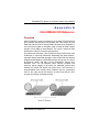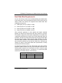
1
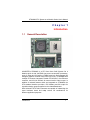
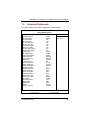
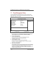
STX88602 STX Form Factor SoM Equipped with VIA EBGA Low Power CPU User’s Manual Disclaimers The information in this manual has been carefully checked and is believed to be accurate. AXIOMTEK Co., Ltd. assumes no responsibility for any infringements of patents or other rights of third parties which may result from its use. AXIOMTEK assumes no responsibility for any inaccuracies that may be contained in this document. AXIOMTEK makes no commitment to update or to keep current the information contained in this manual. AXIOMTEK reserves the right to make improvements to this document and/or product at any time and without notice. No part of this document may be reproduced, stored in a retrieval system, or transmitted, in any form or by any means, electronic, mechanical, photocopying, recording, or otherwise, without the prior written permission of AXIOMTEK Co., Ltd. Copyright 2004 by AXIOMTEK Co., Ltd. All rights reserved. April 2004, Version A1 Printed in Taiwan ii ESD Precautions Integrated circuits on computer boards are sensitive to static electricity. To avoid damaging chips from electrostatic discharge, observe the following precautions: Do not remove boards or integrated circuits from their anti-static packaging until you are ready to install them. Before handling a board or integrated circuit, touch an unpainted portion of the system unit chassis for a few seconds. This helps to discharge any static electricity on your body. Wear a wrist-grounding strap, available from most electronic component stores, when handling boards and components. Trademarks Acknowledgments AXIOMTEK is a trademark of AXIOMTEK Co., Ltd. Award is a registered trademark of Award Software International, Inc. IBM, PS/2 are trademarks of International Business Machines Corporation. Intel and Pentium are registered trademarks of Intel Corporation. Microsoft Windows is a registered trademark of Microsoft Corporation. Other brand names and trademarks are the properties and registered brands of their respective owners. iii This page does not contain any information. iv Table of Contents Chapter 1 Introduction.......................................................1 1.1 General Description..................................................1 1.2 Specifications ...........................................................2 1.3 Utilities Supported....................................................4 Chapter 2 Jumpers and Connectors.................................5 2.1 Board Dimensions ....................................................5 2.2 Board Layout and Fixing Holes...............................6 2.3 Jumper Settings........................................................8 Chapter 3 Installation.........................................................9 錯誤! 尚未定義書籤。3.1 Completing Installation .........9 Chapter 4 Hardware Description...................................11 4.1 4.2 4.3 4.4 4.5 4.6 4.7 4.8 Safety Precaution ...................................................11 CPU ..........................................................................11 BIOS .........................................................................11 System Memory .....................................................11 Device ID Select Table............................................12 I / O Port Address Map ...........................................12 Interrupt Controller.................................................13 Connectors..............................................................14 4.8.1 STX Connector: P1, P2 ............................................ 14 4.8.2 ZV from STX Module: FC2....................................... 21 4.8.3 IDE2 from STX module: FC1.................................... 22 Chapter 5 Display Drivers ..............................................23 5.1 Introduction.............................................................23 Chapter 6 Ethernet ............................................................25 6.1 Introduction.............................................................25 6.2 Features...................................................................25 6.3 Drivers Supported ..................................................25 Table of Contents v Chapter 7 Award BIOS Utility .......................................27 7.1 BIOS Introduction ...................................................27 7.2 BIOS Setup ..............................................................27 7.3 Standard CMOS Setup ...........................................29 7.4 Advanced BIOS Features.......................................33 7.5 Advanced Chipset Features ..................................38 7.6 Integrated Peripherals............................................41 7.7 Power Management Setup .....................................44 7.8 PNP/PCI Configuration...........................................46 7.9 PC Health Status.....................................................48 7.10 Frequency/Voltage Control.................................49 7.11 Load Optimized Defaults.....................................50 7.12 Set Supervisor/User Password ..........................51 7.13 Save & Exit Setup ................................................52 7.14 Exit Without Saving .............................................53 Appendix A Ultra DMA/66/100 Reference...................55 vi Table of Contents STX88602 STX System-on-a-Module Series User’s Manual Chapter 1 Introduction 1.1 General Description AXIOMTEK’s STX88602 is a STX form factor SoM (System On a Module) which is with VIA EBGA low power consumption processors; such as, Eden and C3 families, VT8606 core logic and integrated S3 Savage4 graphics controller with CRT/LCD/TV-out, VT82C686B with multiple I/O features integrated, Realtek RTL8139C/C+ fast Ethernet controller. and AC-link interface for external audio Codec output. In addition of onboard features which are integrated on STX88600, the STX standard interface provides 4 PCI Masters and ISA output for expansion design purpose applied on the related Baseboard. With Axiomtek’s STX SoM, customers are capable of maintaining the same hardware kernel and adapt various I/O combinations for different application purposes. Introduction 1 STX88602 STX System-on-a-Module Series User’s Manual 1.2 Specifications Processor: VIA Eden 400MHz, 667MHz, 800MHz CPU Chipset: VT8606 (Twister-T) + VT82C686B BIOS: Award BIOS with DMI, Plug-and-Play & Y2K Compliant in 4Mbit Flash ROM SmartView VGA BIOS Function; integrated Ethernet RPL and PXE Boot ROM features IDE Support: 2 channels up to 4 devices (IDE1 through STX interface connector, IDE2 through AXIOMTEK 41Pin FPC connector) PIO Mode 0-4, DMA Mode 0-2 and Ultra DMA/33/66/100 LS-120 & ZIP Bootable Multi I/O support: One floppy port (STX interface connector) supporting up to two devices (LS-120 & ZIP Bootable) One SPP/EPP/ECP parallel port (STX interface connector), LS-120 supported Two 16550 UARTs compatible serial ports (STX interface connector) IrDA (STX interface connector) for wireless communcation Keyboard / Mouse support (STX interface connector) Real Time Clock: Integrated in VT82C686B on STX88602 Memory: 1x144-pin SODIMM socket supports SDRAM module maximum up to 512MB 2 Introduction STX88602 STX System-on-a-Module Series User’s Manual Grapgics: VT8606 integrated with UMA VGA memory architecture, maximum sharing system memory up to 32MB Supports CRT and LCD through STX interface connector Supports TV-out and ZV port through AXIOMTEK 41-pin FPC interface Ethernet: RTL8100C integrated on STX Module Wake-On-LAN supported via ATX power supply USB Interface: 4 USB ports (STX interface connector) with USB Spec. Rev. 1.1a compliant Expansion Bus: Four PCI Bus Master Standard ISA Bus Power Management: ACPI (Advanced Configuration and Power Interface) Dimensions: 96x90mm NOTE: Specifications are subject to change without notice. Introduction 3 STX88602 STX System-on-a-Module Series User’s Manual 1.3 Utilities Supported VIA Chipset Driver Ethernet Utility and Drivers VGA Drivers Audio Driver 4 Introduction STX88602 STX System-on-a-Module Series User’s Manual Chapter 2 Jumpers and Connectors 2.1 Board Dimensions Jumpers and Connectors 5 STX88602 STX System-on-a-Module Series User’s Manual 2.2 Board Layout and Fixing Holes Front View Top Side J1 6 FC1 Jumpers and Connectors STX88602 STX System-on-a-Module Series User’s Manual Front View Bottom Side FC2 Jumpers and Connectors 7 STX88602 STX System-on-a-Module Series User’s Manual 2.3 Jumper Settings The jumpers on the STX88602 allow you to configure your CPU card according to the needs of your applications. If you have doubts about the best jumper configuration for your needs, contact your dealer or sales representative. The following table lists the connectors on STX88602 and their respective functions. Jumper J1 LED D5 8 Description CMOS Clear Jumper: default Default Setting Short 1-2 Description +5VSB Power LED Jumpers and Connectors STX88602 STX System-on-a-Module Series User’s Manual Chapter 3 Installation 3.1 Completing Installation To complete the installation, follow the steps listed below. 1. Make sure the power is OFF. 2. Set the configuration jumpers according to the jumper settings on Chapter 2. 3. Install the STX Module into the STX Evaluation Platform base board. 4. Connect the I/O cables and peripherals, i.e. floppy disk, hard disk, monitor, keyboard, power supply and etc. to the STB base board. NOTE: The color of pin one is usually red or blue, while others are gray. 5. Turn ON the system power. Installation 9 STX88602 STX System-on-a-Module Series User’s Manual This Page does not contain any information. 10 Installation STX88602 STX System-on-a-Module Series User’s Manual Chapter 4 Hardware Description 4.1 Safety Precaution Disconnect the power Module from the STX88602 before your installation. Do not make any connections while the power is on because the sudden surge of power could ruin any sensitive components. Most electronic components are sensitive to the static electric charge. Therefore, before touching the STX88602 control board, always ground yourself to keep from any static charge. Use a grounding wrist strap and place all electronic components in any static-shielded devices. 4.2 CPU The STX88602VEA supports an onboard EDEN 400,667or 800MHz CPU. Systems based on these CPUs can be operated under Linux, Windows 98, 2K, XPand MS-DOS environments. Moreover, the installed CPU determines system’s performance. 4.3 BIOS The system BIOS used in STX88602 is Award Plug and Play BIOS. The STX88602 contains a single 4Mbit Flash EPROM and supports power-on modification of the system BIOS. 4.4 System Memory STX88602 has one onboard 144-pin SODIMM sockets, able to support 16MB, 32MB, 64MB, 128MB, 256MB, 512MB SODIMM modules, providing the user with up to 512MB system memory. Hardware Description 11 STX88602 STX System-on-a-Module Series User’s Manual 4.5 Device ID Select Table Item PCI 1 PCI 2 PCI 3 PCI 4 AD 20 AD 21 AD 22 AD 23 Device ID INT#( A ,B ,C ,D ) INT#( D ,A ,B ,C ) INT#( C ,D,A , B ) INT#( B , C,D, A ) Note: Relation between PCI device number and IDSEL mapping depends on the used chipset and may differ on various STX Modules. 4.6 I / O Port Address Map Address 000-01F 020-03F 040-05F 060-06F 070-07F 080-09F 0A0-0BF 0F0 0C0-0DF 0F1 0F8-0FF 120 121 122 1F0-1F8 200-207 300-31F 360-36F 378-37F 3B0-3BF 3C0-3CF 3D0-3DF 3F0-3F7 3F8-3FF 3E8-3EF 2F8-2FF 2E8-2EF 12 Devices DMA controller #1 Interrupt controller #1 Timer Keyboard controller Real time clock, NMI DMA page register Interrupt controller #2 Clear math coprocessor busy signal DMA controller #2 Reset math coprocessor Math processor Disable watchdog timer operation (read) Enable watchdog timer operation (read) Watchdog Fixed disk controller Reserved Prototype card Reserved Parallel port #1 MDA video card (including LPT1) EGA card CGA card Floppy disk controller Serial port #1 (COM1) Serial port #3 (COM3) Serial port #2 (COM2) Serial port #4 (COM4) Hardware Description STX88602 STX System-on-a-Module Series User’s Manual 4.7 Interrupt Controller NMI IRQ0 IRQ1 IRQ2 IRQ3 IRQ4 IRQ5 IRQ6 IRQ7 IRQ8 IRQ9 IRQ10 IRQ11 IRQ12 IRQ13 IRQ14 IRQ15 Hardware Description Parity check error System timer output Keyboard Interrupt rerouting from IRQ8 through IRQ15 Serial port #2 Serial port #1 USB/VGA Floppy disk controller Parallel port #1 Real time clock Logic ISA Serial port #3 Serial port #4 PS/2 Mouse Math coprocessor Primary IDE channel Secondary IDE Channel 13 STX88602 STX System-on-a-Module Series User’s Manual 4.8 Connectors The connectors on the STX88602 allow you to connect external devices such as keyboard, floppy disk drives, hard disk drives, printers, etc. The following table lists the connectors on STX88602 and their respective functions. Connectors STX base board Connector STX base board Connector ZV from STX module IDE2 from STX module SOMIMM1 4.8.1 Label P1 P2 FC2 FC1 SODIMM Socket STX Connector: P1, P2 This chapter provides a detailed description of STX Interface signals. The signals are arranged in functional groups according to their associated interface. All signals are de-scribed from STX Module point of view for example, input means direction from the STX Baseboard to the STX Module. The following table shows pins arangement of either P1, P2 plug (used on STX Module) or J1, J2 receptacle (used on STX Baseboard). Table 1. STX Signal Groups Signal Group PCI ISA E-IDE FDD PPI SPI1 SPI2 IrDA KB/MS USB1 USB2 ETH AC’97 Group Description PCI Bus ISA Bus E-IDE Interface Floppy Disk Drive Interface Parallel Port Interface Serial Port 1 Interface Serial Port 2 Interface IrDA Interface Keyboard and PS/2 Mouse Signals Universal Serial Bus 1 Interface Universal Serial Bus 2 Interface Ethernet 10/100Mbit Interface Audio Codec ‘97 Interface Pins Count 60 88 28 15 17 8 8 2 4 3 3 6 5 To be continued… 14 Hardware Description STX88602 STX System-on-a-Module Series User’s Manual Signal Group CRT FPI FEAT MISC JTAG PWR RSVD Total Group Description CRT Interface Flat Panel Interface Feature Signals Miscellaneous Signals JTAG/Boundary Scan Signals Power and Ground Pins Reserved Pins Pins Count 9 36 7 9 5 81 6 400 Table 2. STX P1 / J1 Connector Pinout Pin 1 3 5 7 9 11 13 15 17 19 21 23 25 27 29 31 33 35 37 39 41 43 45 47 Name GND ACT_LED# LNK_LED# DSK_LED# SPEAKER GNT3# RST_BTN# PWR_BTN# WUE GND KBCLK KBDATA MSCLK MSDATA VCC EXT_SMI# REQ3# CPU_TD_P CPU_TD_N V_BAT VCC AD0 AD1 VCC Group PWR FEAT FEAT FEAT FEAT PCI FEAT FEAT MISC PWR KB/MS KB/MS KB/MS KB/MS PWR MISC PCI MISC MISC PWR PWR PCI PCI PWR Pin 2 4 6 8 10 12 14 16 18 20 22 24 26 28 30 32 34 36 38 40 42 44 46 48 Name NET_TX_P NET_TX_N N.C.(NET_TXCT) NET_RX_P NET_RX_N NET_GND V_SB V_SB PS_ON# AC97_RST# SDATA_IN BIT_CLK SDATA_OUT SYNC GND I2C_SCL I2C_SDA GND IR_RX IR_TX V_CORE VCC VCC AD2 Group ETH ETH ETH ETH ETH ETH PWR PWR MISC AC’97 AC’97 AC’97 AC’97 AC’97 PWR MISC MISC PWR IrDA IrDA MISC PWR PWR PCI To be continued… Hardware Description 15 STX88602 STX System-on-a-Module Series User’s Manual Pin Name 51 53 55 57 59 61 63 65 67 69 71 73 75 77 79 81 83 85 87 89 91 93 95 AD3 GND AD6 AD8 GND AD10 VCC3 (CLKRUN#) AD12 AD15 VCC3 VCC3 PAR GND GND LOCK# VCC3 VCC3 DEVSEL# IRDY# GND GND C/BE2# AD17 VCC3 VCC3 AD19 AD22 USB2_P USB2_N USB3_P USB3_N CLK3 AD25 GND AD28 AD27 97 99 101 103 105 107 109 111 113 115 117 119 121 123 Group PCI PWR PCI PCI PWR PCI PWR RSVD PCI PCI PWR PWR PCI PWR PWR PCI PWR PWR PCI PCI PWR PWR PCI PCI PWR PWR PCI PCI USB2 USB2 USB3 USB3 PCI PCI PWR PCI PCI Pin 52 54 56 58 60 62 64 66 68 70 72 74 76 78 80 82 84 86 88 90 92 94 96 98 100 102 104 106 108 110 112 114 116 118 120 122 124 Name GND C/BE0# AD7 GND AD9 AD11 VCC3 AD14 AD13 VCC3 C/BE1# SERR# GND GND PERR# STOP# VCC3 VCC3 TRDY# FRAME# GND GND AD16 AD18 VCC3 AD21 AD20 VCC3 AD23 PME# GND AD24 C/BE3# GND AD26 AD29 VCC3 Group PWR PCI PCI PWR PCI PCI PWR PCI PCI PWR PCI PCI PWR PWR PCI PCI PWR PWR PCI PCI PWR PWR PCI PCI PWR PCI PCI PWR PCI PCI PWR PCI PCI PWR PCI PCI PWR To be continued… 16 Hardware Description STX88602 STX System-on-a-Module Series User’s Manual Pin 125 127 129 131 133 135 137 139 141 143 145 147 149 151 153 155 157 159 161 163 165 167 169 171 173 175 177 179 181 183 185 187 189 191 193 195 197 199 Name VCC3 AD31 AD30 VCC VCC GNT0# REQ2# GND CLK1 GND CLK0 VCC FP_SCL RST# INTC# INTB# GND FP_VSYNC FP_DSEL FP_VDD_EN FP_BSEL FP_DE VCC FP_D0 FP_D1 FP_D2 FP_D3 GND FP_D4 FP_D5 FP_D6 FP_D7 GND FP_D8 FP_D9 FP_D10 FP_D11 GND Group PWR PCI PCI PWR PWR PCI PCI PWR PCI PWR PCI PWR FPI PCI PCI PCI PWR FPI FPI FPI FPI FPI PWR FPI FPI FPI FPI PWR FPI FPI FPI FPI PWR FPI FPI FPI FPI PWR Hardware Description Pin Name 126 128 130 132 134 136 138 140 142 144 VCC3 REQ1# REQ0# VCC VCC GNT2# GNT1# GND GND CLK2 VCC V_IO FP_SDA INTD# INTA# FP_BKL_EN FP_EDGE FP_HSYNC GND FP_CLK_P GND FP_CLK_S VCC FP_D12 FP_D13 GND FP_D14 FP_D15 FP_D16 FP_D17 GND FP_D18 FP_D19 FP_D20 FP_D21 GND FP_D22 FP_D23 146 148 150 152 154 156 158 160 162 164 166 168 170 172 174 176 178 180 182 184 186 188 190 192 194 196 198 200 Group PWR PCI PCI PWR PWR PCI PCI PWR PWR PCI PWR PCI FPI PCI PCI FPI FPI FPI PWR FPI PWR FPI PWR FPI FPI PWR FPI FPI FPI FPI PWR FPI FPI FPI FPI PWR FPI FPI 17 STX88602 STX System-on-a-Module Series User’s Manual Table 3. STX P2 / J2 Connector Pinout Pin Name 1 3 5 7 9 11 13 15 17 19 21 23 25 27 29 31 33 35 37 39 41 43 45 47 RESET# DD7 DD8 DD6 DD9 DD5 DD10 DD4 DD11 DD3 DD12 DD2 DD13 DD1 DD14 DD0 DD15 INTRQ DMARQ DIOW# DIOR# IORDY DMACK# DA1 DA0 DA2 CS0# CS1# GND DENSEL INDEX# MTR0# DR1# DR0# MTR1# DIR# STEP# 49 51 53 55 57 59 61 63 65 67 69 71 73 Group E-IDE E-IDE E-IDE E-IDE E-IDE E-IDE E-IDE E-IDE E-IDE E-IDE E-IDE E-IDE E-IDE E-IDE E-IDE E-IDE E-IDE E-IDE E-IDE E-IDE E-IDE E-IDE E-IDE E-IDE E-IDE E-IDE E-IDE E-IDE PWR FDD FDD FDD FDD FDD FDD FDD FDD Pin Name 2 4 6 8 10 12 14 16 18 20 22 24 26 28 30 32 34 36 38 40 42 44 46 48 GND IOCHCHK# SD7 RESETDRV SD6 VCC SD5 IRQ9 SD4 GND SD3 DRQ2 SD2 VCC SD1 ENDXFR# SD0 PD66- (GPIO) (GPCS#) 50 52 54 56 58 60 62 64 66 68 70 72 74 IOCHRDY GND MEMCS16# SBHE# AEN SMEMW# IOCS16# LA23 SA19 SMEMR# IRQ10 LA22 SA18 IOW# IRQ11 LA21 SA17 Group PWR ISA ISA ISA ISA PWR ISA ISA ISA PWR ISA ISA ISA PWR ISA ISA ISA E-IDE RSVD RSVD ISA PWR ISA 16 ISA 16 ISA ISA ISA 16 ISA 16 ISA ISA ISA 16 ISA 16 ISA ISA ISA 16 ISA 16 ISA To be continued… 18 Hardware Description STX88602 STX System-on-a-Module Series User’s Manual Pin 75 77 79 81 83 85 87 89 91 93 95 97 99 101 103 105 107 109 111 113 115 117 119 121 123 125 127 129 131 133 135 137 139 141 143 145 147 149 Name WDATA# WGATE# TRK0# WP# RDATA# HDSEL# DSKCHG# GND STB# AFD# PD0 ERR# PD1 INIT# PD2 SLIN# PD3 PD4 PD5 PD6 PD7 ACK# BUSY PE SLCT GND DCD1# SIN1 SOUT1 DTR1# DSR1# RTS1# CTS1# RI1# DCD2# SIN2 SOUT2 DTR2# Group FDD FDD FDD FDD FDD FDD FDD PWR PPI PPI PPI PPI PPI PPI PPI PPI PPI PPI PPI PPI PPI PPI PPI PPI PPI PWR SPI1 SPI1 SPI1 SPI1 SPI1 SPI1 SPI1 SPI1 SPI2 SPI2 SPI2 SPI2 Pin 76 78 80 82 84 86 88 90 92 94 96 98 100 102 104 106 108 110 112 114 116 118 120 122 124 126 128 130 132 134 136 138 140 142 144 146 148 150 Name IOR# IRQ12 LA20 SA16 DACK3# IRQ15 LA19 SA15 DRQ3 IRQ14 LA18 SA14 DACK1# LA17 DACK0# DRQ1 SA13 MEMR# DRQ0 REFRESH# SA12 MEMW# DACK5# SYSCLK SA11 SD8 DRQ5 IRQ7 SA10 SD9 DACK6# IRQ6 SA9 SD10 DRQ6 IRQ5 SA8 SD11 Group ISA ISA 16 ISA 16 ISA ISA ISA 16 ISA 16 ISA ISA ISA 16 ISA 16 ISA ISA ISA 16 ISA 16 ISA ISA ISA 16 ISA 16 ISA ISA ISA 16 ISA 16 ISA ISA ISA 16 ISA 16 ISA ISA ISA 16 ISA 16 ISA ISA ISA 16 ISA 16 ISA ISA ISA 16 To be continued… Hardware Description 19 STX88602 STX System-on-a-Module Series User’s Manual Pin 151 153 155 157 159 161 163 165 167 169 171 173 175 177 179 181 183 185 187 189 191 193 195 197 199 20 Name DSR2# RTS2# CTS2# RI2# GND USB1_N USB1_P GND USB2_N USB2_P GND USB1_OC# USB2_OC# DDC_SCL DDC_SDA GND CRT_G CRT_GND CRT_R CRT_GND CRT_B GND CRT_VS GND CRT_HS Group SPI2 SPI2 SPI2 SPI2 PWR USB1 USB1 PWR USB2 USB2 PWR USB1 USB2 CRT CRT PWR CRT CRT CRT CRT CRT PWR CRT PWR CRT Pin Name 152 154 156 158 160 162 164 166 168 170 172 174 176 178 180 182 184 186 188 190 192 DACK7# IRQ4 SA7 SD12 DRQ7 IRQ3 SA6 SD13 VCC DACK2# SA5 SD14 MASTER# TC SA4 SD15 WUE BALE SA3 VCC SA2 OSC SA1 SA0 GND 194 196 198 200 Group ISA 16 ISA ISA ISA 16 ISA 16 ISA ISA ISA 16 PWR ISA ISA ISA 16 ISA 16 ISA ISA ISA 16 MISC ISA ISA PWR ISA ISA ISA ISA PWR Hardware Description STX88602 STX System-on-a-Module Series User’s Manual 4.8.2 ZV from STX Module: FC2 The ZV-Port or Zoomed Video Port, allows direct transmission of video data from a STX Module to STB Base board. This connector also include EX_LCD singal and TV singal from STX Module. FC2 connector is a 41 Pin 0.5m/m Pitch FPC/FFC-CONN ZIF 90D SMT type connector that provides interfaces for the following functions. Pin # Signal Name Pin # Signal Name 1 2 3 4 5 6 7 8 9 10 11 12 13 14 15 16 17 18 19 20 21 GND GND ZVD0 ZVD1 ZVD2 ZVD3 ZVD4 ZVD5 ZVD6 ZVD7 GND GND ZVD8 ZVD9 ZVD10 ZVD11 ZVD12 ZVD13 ZVD14 ZVD15 GND 22 23 24 25 26 27 28 29 30 31 32 33 34 35 36 37 38 39 40 41 GND ZVREF ZVS ZVCLK GND FPD24(TVD6) FPD25(TVD4) FPD26(TVD5) FPD27(TVD7) FPD28(TVD0) FPD29(TVD1) GND FPD30(TVD3) FPD31(TVVS) FPD32(TVCLK) FPD33(TVD2) FPD34(TVHS) FPD35 Hardware Description 21 STX88602 STX System-on-a-Module Series User’s Manual 4.8.3 IDE2 from STX module: FC1 FC1 connector is a 41 Pin 0.5m/m Pitch FPC/FFC-CONN ZIF 90D SMT type connector that provides interfaces for the following functions. Pin # Signal Name Pin # Signal Name 1 2 3 4 5 6 7 8 9 10 11 12 13 14 15 16 17 18 19 20 21 GND BRSTDRVGND SDD7 SDD8 SDD6 SDD9 GND SDD5 SDD10 SDD4 SDD11 GND GND SDD3 SDD12 SDD2 SDD13 GND SDD1 SDD14 22 23 24 25 26 27 28 29 30 31 32 33 34 35 36 37 38 39 40 41 SDD0 SDD15 GND GND SSDDREQ SSDIOWSSDIORSSDIORDY SSDDACKGND IRQ15 SDA1 SD66GND SDA0 SDA2 SCS1SCS3N.C. GND 22 Hardware Description STX88602 STX System-on-a-Module Series User’s Manual Chapter 5 Display Drivers 5.1 Introduction The Twister-T integrates S3 Graphics 128-bit ProSavage4 graphics accelerator into a single chip. TwisterT brings ainstream graphics performance to the Value PC with leading-edge 2D, 3D and DVD video acceleration into a cost effective package.Based on its capabilities, TwisterT is an ideal solution for the consumer, corporate obile users and entry level professionals. The industry ’s first integrated AGP 4X solution, TwisterT combines AGP 4X performance with Microsoft Direct-X texture compression and assive 2Kx2K textures to deliver unprecedented 3D performance and i age quality for the Value PC obilemarket.5.2 Features High-Performance 3D Accelerator 128-bit 2D Graphics Engine DVD Playback and Video onferencing LCD and Flat Panel Monitor Support High Screen Resolution CRT Support Display Drivers 23 STX88602 STX System-on-a-Module Series User’s Manual This Page does not contain any information. 24 Display Drivers STX88602 STX System-on-a-Module Series User’s Manual Chapter 6 Ethernet 6.1 Introduction The STX88602 is equipped with a high performance Plug and Play Ethernet interface which is fully compliant with the IEEE 802.3 standard. 6.2 Features 10Mb/s and 100Mb/s operations Supports 10Mb/s and 100Mb/s N-Way auto negotiation Full duplex capability Full compliance with PCI Revision 2.1 PCI Bus Master data transfers 6.3 Drivers Supported Bundled with popular software drivers, the STX88602 Ethernet interface allows great flexibility to work with all major networking operating systems including Novell NetWare v2.x, v3.x, v4.x, Microsoft LAN Manager, Win3.1, Win NT, Win95, IBM LAN Server, SCO UNIX or other ODI, NDIS and Packet drive compliant operating systems. Ethernet 25 STX88602 STX System-on-a-Module Series User’s Manual This Page does not contain any information. 26 Ethernet STX88602 STX System-on-a-Module Series User’s Manual Chapter 7 Award BIOS Utility The different settings are available in the Award BIOS and along with the STX88602 board. Also contained here are instructions on how to set up the BIOS configuration. 7.1 BIOS Introduction The Award BIOS (Basic Input/Output System) installed in your computer system’s ROM supports Intel Celeron processors in a standard IBM-AT compatible I/O system. The BIOS provides critical low-level support for standard devices such as disk drives, serial and parallel ports. It also adds virus and password protection as well as special support for detailed fine-tuning of the chipset controlling the entire system. 7.2 BIOS Setup The Award BIOS provides a Setup utility program for specifying the system configurations and settings. The BIOS ROM of the system stores the Setup utility. When you turn ON the computer, the Award BIOS is immediately activated. Pressing the <Del> key immediately allows you to enter the Setup utility. If you are a little bit late pressing the <Del> key, POST (Power On Self Test) will continue with its test routines, thus preventing you from invoking the Setup. If you still wish to enter Setup, restart the system by pressing the ”Reset” button or simultaneously pressing the <Ctrl>, <Alt> and <Delete> keys. You can also restart by turning the system OFF and back ON again. The following message will appear on the screen: Press <DEL> to Enter Setup In general, you press the arrow keys to highlight items, <Enter> to select, the <PgUp> and <PgDn> keys to change entries, <F1> for help and <Esc> to quit. When you enter the Setup utility, the Main Menu screen will appear on the screen. The Main Menu allows you to select from various setup functions and exit choices. Award BIOS Utility 27 STX88602 STX System-on-a-Module Series User’s Manual When you enter the Setup utility, the Main Menu screen will appear on the screen. The Main Menu allows you to select from various setup functions and exit choices. Phoenix – AwardBIOS CMOS Setup Utility Standard CMOS Features Frequency/Voltage Control Advanced BIOS Features Load Optimized Defaults Advanced Chipset Features Set Supervisor Password Integrated Peripherals Set User Password Power Management Setup Save & Exit Setup PnP/PCI Configurations Exit Without Saving PC Health Status Esc : Quit F9: Menu in BIOS F10 : Save & Exit Setup ← : Select Item Time, Date, Hard Disk Type… The section below the setup items of the Main Menu displays the control keys for this menu. Another section located at the bottom of the Main Menu, just below the control keys section, displays information on the currently highlighted item in the list. NOTE: If you find that your computer cannot boot after making and saving system changes with Setup, the Award BIOS, via its builtin override feature, resets your system to the CMOS default settings. We strongly recommend that you avoid making any changes to the chipset defaults. These defaults have been carefully chosen by both Award and your system manufacturer to provide the absolute maximum performance and reliability. 28 Award BIOS Utility STX88602 STX System-on-a-Module Series User’s Manual 7.3 Standard CMOS Setup “Standard CMOS Setup” allows you to record some basic hardware configurations in your computer system and set the system clock and error handling. If the motherboard is already installed in a working system, you will not need to select this option. You will need to run the Standard CMOS option, however, if you change your system hardware configurations, the onboard battery fails, or the configuration stored in the CMOS memory was lost or damaged. Phoenix – AwardBIOS CMOS Setup Utility Standard CMOS Features Date (mm:dd:yy) Thu, Mar 6 2003 Time (hh:mm:ss) 00 : 0 : 00 IDE Primary Master IDE Primary Slave IDE Secondary Master IDE Secondary Slave Drive A Drive B 1.44M, 3.5 in. None LCD Type Screen Expansion TV Type Display Type During Post Display Type After Post Halt on T9 800x600 TFT Enable NTSC VGA Default VGA Default All, But keyboard Base Memory Extended Memory 640K 65535K Item Help Menu Level Change the Day, month, Year and Century : Move Enter: Select +/-/PU/PD: Value F10: Save ESC: Exit F1: General Help F5: Previous Values F7: Optimized Defaults At the bottom of the menu are the control keys for use on this menu. If you need any help in each item field, you can press the <F1> key. It will display the relevant information to help you. The memory display at the lower right-hand side of the menu is read-only. It will adjust automatically according to the memory changed. The following pages describe each item of this menu. Award BIOS Utility 29 STX88602 STX System-on-a-Module Series User’s Manual Date The date format is <day>, <date> <month> <year>. Press <F3> to show the calendar. day date month year The day of week, from Sun to Sat, determined by the BIOS, is read only The date, from 1 to 31 (or the maximum allowed in the month), can key in the numerical / function key The month, Jan through Dec. The year, depends on the year of BIOS Time The time format is <hour> <minute> <second> accepting either function key or numerical key. The time is calculated based on the 24-hour militarytime clock. For example, 1 p.m. is 13:00:00. IDE Primary Master/Primary Slave/Secondary Master/Secondary Slave The categories identify the types of one channel that have been installed in the computer. There are 45 predefined types and 2 user definable types are for Enhanced IDE BIOS. Type 1 to Type 45 are predefined. Type User is user-definable. Press <PgUp>/<+> or <PgDn>/<−> to select a numbered hard disk type or type the number and press <Enter>. Note that the specifications of your drive must match with the drive table. The hard disk will not work properly if you enter improper information within this category. If your hard disk drive type does not match or is not listed, you can use Type User to define your own drive type manually. If you select Type User, related information is asked to be entered to the following items. Enter the information directly from the keyboard and press <Enter>. This information should be provided in the documentation from your hard disk vendor or the system manufacturer. If the controller of HDD interface is ESDI, select “Type 1”. If the controller of HDD interface is SCSI, select “None”. If the controller of HDD interface is CD-ROM, select “None”. CYLS. number of cylinders HEADS number of heads PRECOMP write precom LANDZONE landing zone SECTORS number of sectors MODE HDD access mode If there is no hard disk drive installed, select NONE and press <Enter>. 30 Award BIOS Utility STX88602 STX System-on-a-Module Series User’s Manual Drive A type/Drive B type The category identifies the types of floppy disk drive A or drive B installed in the computer. None 360K, 5.25 in 1.2M, 5.25 in 720K, 3.5 in 1.44M, 3.5 in 2.88M, 3.5 in No floppy drive installed 5.25 inch PC-type standard drive; 360Kb capacity 5.25 inch AT-type high-density drive; 1.2MB capacity 3.5 inch double-sided drive; 720Kb capacity 3.5 inch double-sided drive; 1.44MB capacity 3.5 inch double-sided drive; 2.88MB capacity . LCD Type This item selection includes: T0 640x480 TFT T1 800x600 TFT T2 1024x768 TFT T3 1280x1024 TFT T4 640x480 DSTN T5 800x600 DSTN T6 1024x768 DSTN T7 1024x768 TFT T8 640x480 TFT T9 800x600 TFT T10 1024x768 TFT T11 1280x1024 TFT T12 1400x1050 DSTN T13 800x600 DSTN T14 1024x768 DSTN T15 1280x1024 DSTN TV Type This item selection includes NTSC and PAL Display Type During Post This item selection includes VGA DEFAULT, CRT, LCD, CRT+LCD, TV, and CRT+TV. Display Type After Post This item selection includes VGA DEFAULT, CRT, LCD, CRT+LCD, TV, and CRT+TV. Award BIOS Utility 31 STX88602 STX System-on-a-Module Series User’s Manual Halt On This field determines whether the system will halt if an error is detected during power up. No errors All errors All, But Keyboard All, But Diskette All, But Disk/Key 32 The system boot will halt on any error detected. (default) Whenever the BIOS detects a non-fatal error, the system will stop and you will be prompted. The system boot will not stop for a keyboard error; it will stop for all other errors. The system boot will not stop for a disk error; it will stop for all other errors. The system boot will not stop for a keyboard or disk error; it will stop for all other errors. Award BIOS Utility STX88602 STX System-on-a-Module Series User’s Manual 7.4 Advanced BIOS Features This section allows you to configure and improve your system and allows you to set up some system features according to your preference. Phoenix – AwardBIOS CMOS Setup Utility Advanced BIOS Features Virus Warning Disabled Item Help CPU Internal Cache Enabled External Cache Enabled Menu Level CPU L2 Cache ECC Checking Enabled Processor Number Feature Enabled Allows you to Quick Power On Self Test Enabled choose the VIRUS First Boot Device Floppy warning feature Second Boot Device HDD-0 for IDE Hard disk Third Boot Device LS120 boot sector Boot Other Device Enabled protection. If this Onboard Lan boot Rom Disable Optimized default select BIOS O ptimized Cardbus IRQ Mode select PCKN4000 Swap Floppy Drive Disabled function is enable Boot Up Floppy Seek Enabled and someone Boot Up NumLock Status On attempts to write Gate A20 Option Fast data into this area, Typematic Rate Setting Disabled BIOS will show Typematic Rate (Chars/Sec) 6 a warning Typematic Delay (Msec) 250 message on Security Option Setup screen and alarm PS/2 Mouse Control Enable beep OS Select For DRAM > 64MB Non-OS2 Video BIOS Shadow Enabled C8000-CBFFF Shadow Disabled CC000-CFFFF Shadow Disabled D0000-D3FFF Shadow Disabled D4000-D7FFF Shadow Disabled D8000-DBFFF Shadow Disabled DC000-DFFFF Shadow Disabled Small Logo(EPA) Show Disabled : Move Enter: Select +/-/PU/PD: Value F10: Save ESC: Exit F1: General Help F5: Previous Values F7: Optimized Defaults Award BIOS Utility 33 STX88602 STX System-on-a-Module Series User’s Manual Virus Warning This item protects the boot sector and partition table of your hard disk against accidental modifications. If an attempt is made, the BIOS will halt the system and display a warning message. If this occurs, you can either allow the operation to continue or run an anti-virus program to locate and remove the problem. NOTE: Many disk diagnostic programs, which attempt to access the boot sector table, can cause the virus warning. If you will run such a program, disable the Virus Warning feature. CPU Internal Cache / External Cache Cache memory is additional memory that is much faster than conventional DRAM (system memory). CPUs from 486-type on up contain internal cache memory, and most, but not all, modern PCs have additional (external) cache memory. When the CPU requests data, the system transfers the requested data from the main DRAM into cache memory, for even faster access by the CPU. These items allow you to enable (speed up memory access) or disable the cache function. By default, these are Enabled. CPU L2 Cache ECC Checking When enabled, this allows ECC checking of the CPU’s L2 cache. By default, this field is Enabled. Processor Number Feature When a Pentium III CPU is installed, the system automatically detects it and displays this item. Quick Power On Self Test This option speeds up Power On Self Test (POST) after you turn on the system power. If set as Enabled, BIOS will shorten or skip some check items during POST. The default setting is “Enabled”. Enabled Disabled Enable Quick POST Normal POST First/Second/Third Boot Device These items allow the selection of the 1st, 2nd, and 3rd devices that the system will search for during its boot-up sequence. The wide range of selection includes Floppy, LS120, ZIP100, HDD0~3, SCSI, and CDROM. Boot Other Device This item allows the user to enable/disable the boot device not listed on the First/Second/Third boot devices option above. The default setting is Enabled. 34 Award BIOS Utility STX88602 STX System-on-a-Module Series User’s Manual Onboard Lan boot Choice Enable when you need boot on Lan Funtion, Like PXE ,RPL Optimized default Select This item allows you load bios default setup or your previous setup . [BIOS Optimized] Choice Bios Optimized than save & exit . Next time when you Run [DEL] to setup items Main Menu Load Optimized Defaults ,system will load bios defaults setting . [Previous Setup] Choice Previous setup than save & exit . Next time when you Run [DEL] to setup items Main Menu .Bios will backup your change to Flash bios .Than save & exit .Your setting will be save and can’t be clear until you change the setting to Bios Optimized than save & exit . Swap Floppy Drive This allows you to determine whether to enable Swap Floppy Drive or not. When enabled, the BIOS swaps floppy drive assignments so that Drive A becomes Drive B, and Drive B becomes Drive A. By default, this field is set to Disabled. Boot Up Floppy Seek During POST, BIOS will determine the floppy disk drive type, 40 or 80 tracks, installed in the system. 360Kb type is 40 tracks while 720Kb, 1.2MB and 1.44MB are all 80 tracks. The default value is “Enabled”. Enabled Disabled BIOS searches for floppy disk drive to determine if it is 40 or 80 tracks. Note that BIOS can not tell from 720K, 1.2M or 1.44M drive type as they are all 80 tracks. BIOS will not search for the type of floppy disk drive by track number. There will be no warning message displayed if the drive installed is 360K. Boot Up NumLock Status This option enables and disables the numberlock function of the keypad. The default value is “On”. On Off Keypad functions confine with numbers Keypad functions convert to special functions (i.e., left/right arrow keys) Award BIOS Utility 35 STX88602 STX System-on-a-Module Series User’s Manual Gate A20 Option The default value is “Fast”. Normal Fast The A20 signal is controlled by keyboard controller or chipset hardware. Default: Fast. The A20 signal is controlled by Port 92 or chipset specific method. Typematic Rate Setting This determines the typematic rate of the keyboard. The default value is “Disabled”. Enabled Disabled Enable typematic rate and typematic delay programming Disable typematic rate and typematic delay programming. The system BIOS will use default value of these 2 items and the default is controlled by keyboard. Typematic Rate (Chars/Sec) This option refers to the number of characters the keyboard can type per second. The default value is “6”. 6 8 10 12 15 20 24 30 6 characters per second 8 characters per second 10 characters per second 12 characters per second 15 characters per second 20 characters per second 24 characters per second 30 characters per second Typematic Delay (Msec) This option sets the display time interval from the first to the second character when holding a key. The default value is “250”. 250 500 750 1000 36 250 msec 500 msec 750 msec 1000 msec Award BIOS Utility STX88602 STX System-on-a-Module Series User’s Manual Security Option This item allows you to limit access to the system and Setup, or just to Setup. The default value is “Setup”. System Setup NOTE: The system will not boot and access to Setup will be denied if the incorrect password is entered at the prompt. The system will boot, but access to Setup will be denied if the correct password is not entered at the prompt. To disable security, select PASSWORD SETTING at Main Menu and then you will be asked to enter password. Do not type anything, just press <Enter> and it will disable security. Once the security is disabled, the system will boot and you can enter Setup freely. PS/2 Mouse Control OS Select for DRAM > 64MB This segment is specifically created for OS/2 when DRAM is larger than 64MB. If your operating system is OS/2 and DRAM used is larger the 64MB, you have to select “OS 2”, otherwise (under non-OS2), default is NON-OS2. The default value is “Non-OS2”. Video BIOS Shadow Video shadowing increases the video speed by copying the video BIOS into RAM. However, it is still optional depending on the chipset design. The default value of this option is “Enabled”. Enabled Disabled Video BIOS shadowing is enabled Video BIOS shadowing is disabled C8000 - CBFFF Shadow/DC000 - DFFFF Shadow Shadowing ROM reduces available memory between 640KB and 1024KB. These fields determine whether optional ROM is copied to RAM or not. Award BIOS Utility 37 STX88602 STX System-on-a-Module Series User’s Manual 7.5 Advanced Chipset Features Since the features in this section are related to the chipset on the CPU board and are completely optimized, you are not recommended to change the default settings in this setup table unless you are well oriented with the chipset features. Phoenix – AwardBIOS CMOS Setup Utility Advanced Chipset Features DRAM Timing By SPD Enabled Item Help DRAM Clock Host CLK SDRAM Cycle Length 3 Menu Level Bank Interleave Disabled Memory Hole Disabled P2C/C2P Concurrency Enabled System BIOS Cacheable Disabled Video RAM Cacheable Disabled Frame Buffer Size 16M AGP Aperture Size 64M AGP-4X Mode Enabled USB Port1 & Port2 Enabled USB Port3 & Port4 Disabled USB Keyboard Support Disabled OnChip Sound Auto CPU to PCI Write Buffer Enabled PCI Dynamic Bursting Enabled PCI Master 0 WS Write Enabled PCI Delay Transaction Disabled PCI#2 Access #1 Retry Enabled AGP Master 1 WS Write Disabled AGP Master 1 WS Read Disabled : Move Enter: Select +/-/PU/PD: Value F10: Save ESC: Exit F1: General Help F5: Previous Values F7: Optimized Defaults DRAM Timing By SPD This item allows you to select the value in this field, depending on whether the board has paged DRAMs or EDO (extended data output) DRAMs. 38 Award BIOS Utility STX88602 STX System-on-a-Module Series User’s Manual DRAM Clock This item allows you to select the DRAM clock value, depending on whether the board has paged DRAMs or EDO (extended data output) DRAMs. The available choices are 66 MHz and Host CLK. SDRAM Cycle Length When synchronous DRAM is installed, the number of clock cycles of CAS latency depends on the DRAM timing. Do not reset this field from the default value specified by the system designer. The default setting is 3. Memory Hole To improve performance, certain space in memory is reserved for ISA cards. This memory must be mapped into the memory space below 16MB. The available choices are 15M-16M and Disabled. P2C/C2P Concurrency This item allows you to enable/disable the PCI to CPU, CPU to PCI concurrency. By default, this field is set to Enabled. System BIOS Cacheable Selecting Enabled allows caching of the system BIOS ROM at F0000hFFFFFh, resulting in better system performance. However, if any program writes to this memory area, a system error may result. The choice: Enabled, Disabled. Video RAM Cacheable Select Enabled allows caching of the A/B segment, resulting in better system performance. The Choice: Enabled, Disabled. AGP Aperture Size The field sets aperture size of the graphics. The aperture is a portion of the PCI memory address range dedicated for graphics memory address space. Host cycles that hit the aperture range are forwarded to the AGP without any translation. The options available are 4M, 8M, 16M, 32M, 64M, 128M and 256M. USB Port1(3) & Port2(4) This should be enabled if your system has a USB installed on the system board and you wish to use it. Even when so equipped, if you add a higher performance controller, you will need to disable this feature. The available choices are Enabled and Disabled. Award BIOS Utility 39 STX88602 STX System-on-a-Module Series User’s Manual USB Keyboard Support Select Enabled if your system contains a Universal Serial Bus (USB) controller and you have a USB keyboard. The options available are Enabled, Disabled. CPU to PCI Write Buffer When this field is Enabled, writes from the CPU to the PCI bus are buffered, to compensate for the speed differences between the CPU and the PCI bus. When Disabled, the writes are not buffered and the CPU must wait until the write is complete before starting another write cycle. buffered and the CPU must wait until the write is complete before starting another write cycle. PCI Dynamic Bursting This item allows you to enable/ disable the PCI dynamic bursting function. PCI Master 0 WS Write When Enabled, writes to the PCI bus are executed with zero wait states. PCI Delay Transaction The chipset has an embedded 32-bit posted write buffer to support delay transactions cycles. Select Enabled to support compliance with PCI specification version 2.1. The default setting is Disabled. PCI#2 Access #1 Retry When disabled, PCI#2 will not be disconnected until access finishes (default). When enabled, PCI#2 will be disconnected if max retries are attempted without success. AGP Master 1 WS Write When Enabled, writes to the AGP(Accelerated Graphics Port) are executed with one wait states.. AGP Master 1 WS Read When Enabled, read to the AGP (Accelerated Graphics Port) are executed with one wait states.. 40 Award BIOS Utility STX88602 STX System-on-a-Module Series User’s Manual 7.6 Integrated Peripherals This option sets your hard disk configuration, mode and port. Phoenix – AwardBIOS CMOS Setup Utility Integrated Peripherals OnChip IDE Channel0 Enabled Item Help Enabled OnChip IDE Channel1 IDE Prefetch Mode Enabled Menu Level Primary Master PIO Auto Primary Slave PIO Auto Secondary Master PIO Auto Secondary Slave PIO Auto Primary Master UDMA Auto Primary Slave UDMA Auto Secondary Master UDMA Auto Secondary Slave UDMA Auto Init Display First PCI Slot IDE HDD Block Mode Enabled Onboard FDD Controller Enabled Onboard Serial Port 1 3F8/IRQ4 Onboard Serial Port 2 2F8/IRQ3 UART 2 Mode Standard IR Function Duplex Half TX, RX inverting enable No, Yes Onboard Parallel Port 378/IRQ7 Onboard Parallel Mode Normal ECP Mode Use DMA 3 Parallel Port EPP Type EPP1.9 Onboard Serial Port 3 3E8H Serial Port 3 Use IRQ IRQ10 Onboard Serial Port 4 2E8H Serial Port 4 Use IRQ IRQ11 Onboard Legacy Audio Enabled Sound Blaster Disabled SB I/O Base Address 220H SB IRQ Select IRQ 5 SB DMA Select DMA 1 MPU-401 Disabled MPU-401 I/O Address 330-333H : Move Enter: Select +/-/PU/PD: Value F10: Save ESC: Exit F1: General Help F5: Previous Values F7: Optimized Defaults Award BIOS Utility 41 STX88602 STX System-on-a-Module Series User’s Manual On-Chip IDE Channel0/Channel1 The integrated peripheral controller contains an IDE interface with support for two IDE channels. Select Enabled to activate each channel separately. The choice: Enabled, Disabled. IDE Prefetch Mode The onboard IDE drive interfaces supports IDE prefetching for faster drive accesses. If you install a primary and/or secondary add-in IDE interface, set this field to Disabled if the interface does not support prefetching. Primary/Secondary Master/Slave PIO The four PIO (Programmed Input/Output) fields let you set a PIO mode (04) for each of the four IDE devices that the onboard IDE interface supports. Modes 0 through 4 provide successively increased performance. In Auto mode, the system automatically determines the best mode for each device. The choice: Auto, Mode 0, Mode 1, Mode 2, Mode 3, Mode 4. Primary/Secondary Master/Slave UDMA Ultra DMA/33 implementation is possible only if your IDE hard drive supports it and the operating environment includes a DMA driver (Windows 98 or a third-party IDE bus master driver). If your hard drive and your system software both support Ultra DMA/33, select Auto to enable BIOS support. The Choice: Auto, Disabled. Init Display First This item allows you to decide to active whether PCI Slot or on-chip VGA first. The choice: PCI Slot, Onboard. IDE HDD Block Mode Block mode is also called block transfer, multiple commands, or multiple sector read/write. If your IDE hard drive supports block mode (most new drives do), select Enabled for automatic detection of the optimal number of block read/writes per sector the drive can support. The choice: Enabled, Disabled 42 Award BIOS Utility STX88602 STX System-on-a-Module Series User’s Manual Onboard FDD Controller Select Enabled if your system has a floppy disk controller (FDC) installed on the system board and you wish to use it. If you install and-in FDC or the system has no floppy drive, select Disabled in this field. The choice: Enabled, Disabled. Onboard Serial Port 1/Port 2 Select an address and corresponding interrupt for the first, second and twist serial ports. The choice: 3F8/IRQ4, 2E8/IRQ3, 3E8/IRQ4, 2F8/IRQ3, Disabled, Auto. UART 2 Mode This item allows you to select UART mode. By default, this field is set to Standard. IR Function Duplex This item allows you to select the IR half/full duplex funcion. TX,RX inverting enable This item allow you to enable the TX, RX inverting which depends on different H/W requirement. This field is not recommended to change its default setting for avoiding any error in your system. Onboard Parallel Port This item allows you to determine access onboard parallel port controller with which I/O address. The choice: 3BC/IRQ7, 378/IRQ7, 278/IRQ5, Disabled. Onboard Parallel Mode Select an operating mode for the onboard parallel (printer) port. Select Normal, Compatible, or SPP unless you are certain your hardware and software both support one of the other available modes. The choice: SPP, EPP, ECP, ECP+EPP. ECP Mode Use DMA Select a DMA channel for the parallel port for use during ECP mode. The choice: 3, 1. Award BIOS Utility 43 STX88602 STX System-on-a-Module Series User’s Manual 7.7 Power Management Setup The Power Management Setup allows you to save energy of your system effectively. It will shut down the hard disk and turn OFF video display after a period of inactivity. Phoenix – AwardBIOS CMOS Setup Utility Power Management Setup ACPI Function Disabled Item Help Power Management Press Enter PM Control by APM Yes Menu Level Video Off Option Suspend -> Off Video Off Method V/H SYNC+Blank MODEM Use IRQ 3 Soft-Off by PWRBTN Instant-Off Wake Up Events Press Enter : Move Enter: Select +/-/PU/PD: Value F10: Save ESC: Exit F1: General Help F5: Previous Values F7: Optimized Defaults ACPI Function This item allows you to enable/disable the Advanced Configuration and Power Management (ACPI). The choice: Enabled, Disabled. Power Management This item allows you to select the Power Management mode. The choice: User Define, Min Saving, Max Saving. ACPI Suspend Type This item allows you to select the APCI suspend type. S1 (POS) => Power On Suspend, S3 (STR) => Suspend To DRAM The choice: S1 (POS), S3 (STR). PM Control by APM When enabled, an Advanced Power Management device will be activated to enhance the Max. Power Saving mode and stop the CPU internal clock. If Advance Power Management (APM) is installed on your system, selecting Yes gives better power savings. If the Max. Power Saving is not enabled, this will be preset to No. 44 Award BIOS Utility STX88602 STX System-on-a-Module Series User’s Manual Video Off Option When enabled, this feature allows the VGA adapter to operate in a power saving mode. Always On Monitor will remain on during power saving modes. Monitor blanked when the system enters the Suspend mode. Suspend --> Off Monitor blanked when the system enters either Suspend or Standby modes. Monitor blanked when the system enters any power saving mode. Susp,Stby --> Off All Modes --> Off Video Off Method This determines the manner in which the monitor is blanked. V/H SYNC + Blank This causes the system to turn off the vertical and horizontal synchronization ports and write blanks to the video buffer. Select this option if your monitor supports the Display Power Management Signaling (DPMS) standard of the Video Electronics Standards to select video power management values. This option only writes blanks to the video buffer. DPMS Blank Screen Video Off Method In suspending, this item allows you to select the CRT closed method under APM mode. The choice: Blank Screen, V/H SYNC+Blank, DPMS MODEM Use IRQ APM 1.2 function used only. The choice: NA, 3, 4, 5, 7, 9, 10, 11 Soft-off by PWRBTN This only works with systems using an ATX power supply. It also allows tser to define the type of soft power OFF sequence the system will follow. Instant-Off (default) Delay 4 Sec. This option follows the conventional manner systems perform when power is turned OFF. Instant-Off is a soft power OFF sequence requiring only the switching of the power supply button to OFF. Upon turning OFF system from the power switch, this option will delay the complete system power OFF sequence by approximately 4 seconds. Within this delay period, system will temporarily enter into Suspend Mode enabling you to restart the system at once. Wake Up Events An input signal on the network 2 awakens the system from a soft-off state. Award BIOS Utility 45 STX88602 STX System-on-a-Module Series User’s Manual 7.8 PNP/PCI Configuration This section describes configuring the PCI bus system. PCI, or Personal Computer Interconnect, is a system which allows I/O devices to operate at speeds nearing the speed the CPU itself uses when communicating with its own special components. This section covers some very technical items and it is strongly recommended that only experienced users should make any changes to the default settings. Phoenix – AwardBIOS CMOS Setup Utility PnP/PCI Configurations PNP OS Installed No Item Help Reset Configuration Data Disabled Menu Level Resources Controlled By Manual IRQ Resources Press Enter Select Yes if you are DMA Resources Press Enter using a Plug and play capable operating PCI/VGA Palette Snoop Disabled system select No if Assign IRQ For VGA Enabled you need the BIOS to Assign IRQ For USB Enabled configure non-boot devices : Move Enter: Select +/-/PU/PD: Value F10: Save ESC: Exit F1: General Help PNP OS Installed This item allows you to determine install PnP OS or not. The options available are Yes and No. Reset Configuration Data Normally, you leave this field Disabled. Select Enabled to reset Extended System Configuration Data (ESCD) when you exit Setup or if you have installed a new add-on and the system reconfiguration has caused such a serious conflict that the operating system can not boot. The options available are Enabled and Disabled. 46 Award BIOS Utility STX88602 STX System-on-a-Module Series User’s Manual Resource controlled by The Award Plug and Play BIOS has the capacity to automatically configure all of the boot and Plug and Play compatible devices. However, this capability means absolutely nothing unless you are using a Plug and Play operating system such as Windows98. The options available are Auto and Manual. IRQ Resources When resources are controlled manually, assign each system interrupt a type, depending on the type of device using the interrupt. DMA Resources When resources are controlled manually, assign each system DMA channel as one of the following types, depending on the type of device using the interrupt: Legacy ISA Devices compliant with the original PC AT bus specification, requiring a specific DMA channel. PCI/ISA PnP Devices compliant with the Plug and Play standard, whether designed for PCI or ISA bus architecture. The default value is “PCI/ISA PnP”. PCI/VGA Palette Snoop Leave this field at Disabled. The choice: Enabled, Disabled. Assign IRQ For USB/VGA Enable/Disable to assign IRQ for USB/VGA. The options available are Enabled, Disabled Award BIOS Utility 47 STX88602 STX System-on-a-Module Series User’s Manual 7.9 PC Health Status Phoenix – AwardBIOS CMOS Setup Utility PC Health Status Current CPU Temp. Current System Temp. Vcore 2.5V 3.3V 5V Menu Level : Move Enter: Select +/-/PU/PD: Value F10: Save ESC: Exit F1: General Help F5: Previous Values F7: Optimized Defaults . Current CPU Temp. Show you the current CPU temperature. Current System Temp. These read-only fields reflect the functions of the hardware thermal sensor that monitors the chip blocks and system temperatures to ensure the system is stable. Vcore/2.5V/3.3V/5V Show the voltage of Vcore/2.5V/3.3V/5V. 48 Award BIOS Utility STX88602 STX System-on-a-Module Series User’s Manual 7.10 Frequency/Voltage Control CMOS Setup Utility-Copyright © 1984-2001 Award Software Frequency/Voltage Control Auto Detect DIMM/PCI Clk Enabled Spread Spectrum Disabled Menu Level CPU Host/PCI Clock Default : Move Enter: Select +/-/PU/PD: Value F10: Save ESC: Exit F1: General Help F5: Previous Values F7: Optimized Defaults Auto Detect DIMM/PCI Clk When enabled, this item will auto detect if the DIMM and PCI socket have devices and will send clock signal to DIMM and PCI devices. When disabled, it will send the clock signal to all DIMM and PCI socket. The choice: Enabled, Disabled. Spread Spectrum This item allows you to enable/disable the spread spectrum modulate. The choice: Enabled, Disabled. Award BIOS Utility 49 STX88602 STX System-on-a-Module Series User’s Manual 7.11 Load Optimized Defaults This option allows you to load the default values to your system configuration. These default settings are optimal and enable all high performance features. Phoenix – AwardBIOS CMOS Setup Utility Standard CMOS Features Frequency/Voltage Control Advanced BIOS Features Load Optimized Defaults Advanced Chipset Features Set Supervisor Password Integrated Peripherals Set User Password Power Man Load Optimized Defaults (Y/N)? N PnP/PCI Co PC Health Status Esc : Quit F10 : Save & Exit Setup : Select Item Load Optimized Defaults To load SETUP defaults value to CMOS SRAM, enter “Y”. If not, enter “N”. 50 Award BIOS Utility STX88602 STX System-on-a-Module Series User’s Manual 7.12 Set Supervisor/User Password You can set either supervisor or user password, or both of then. The differences between are: supervisor password: can enter and change the options of the setup menus. user password: just can enter but do not have the right to change the options of the setup menus. When you select this function, the following message will appear at the center of the screen to assist you in creating a password. ENTER PASSWORD: Type the password with eight characters at most, and press <Enter>. The password typed will now clear any previously entered password from CMOS memory. You will be asked to confirm the password. Type the password again and press <Enter>. You may also press <Esc> to abort the selection and not enter a password. To disable password, just press <Enter> when you are prompted to enter password. A message will confirm the password being disabled. Once the password is disabled, the system will boot and you can enter Setup freely. PASSWORD DISABLED. When a password is enabled, you have to type it every time you enter Setup. This prevents any unauthorized person from changing your system configuration. Additionally when a password is enabled, you can also require the BIOS to request a password every time the system reboots. This would prevent unauthorized use of your computer. You determine when the password is required within the BIOS Features Setup Menu and its Security option. If the Security option is set to “System”, the password is required during boot up and entry into Setup. If set as “Setup”, prompting will only occur prior to entering Setup. Award BIOS Utility 51 STX88602 STX System-on-a-Module Series User’s Manual 7.13 Save & Exit Setup This allows you to determine whether or not to accept the modifications. Typing “Y” quits the setup utility and saves all changes into the CMOS memory. Typing “N” brigs you back to Setup utility. Phoenix – AwardBIOS CMOS Setup Utility Standard CMOS Features Frequency/Voltage Control Advanced BIOS Features Load Optimized Defaults Advanced Chipset Features Set Supervisor Password Integrated Peripherals Set User Password Power Man SAVE to CMOS and EXIT (Y/N)? Y PnP/PCI Con PC Health Status Esc : Quit F10 : Save & Exit Setup : Select Item Save Data to CMOS 52 Award BIOS Utility STX88602 STX System-on-a-Module Series User’s Manual 7.14 Exit Without Saving Select this option to exit the Setup utility without saving the changes you have made in this session. Typing “Y” will quit the Setup utility without saving the modifications. Typing “N” will return you to Setup utility. Phoenix – AwardBIOS CMOS Setup Utility Standard CMOS Features Frequency/Voltage Control Advanced BIOS Features Load Optimized Defaults Advanced Chipset Features Set Supervisor Password Integrated Peripherals Set User Password Power Man Quit Without Saving (Y/N)? N PnP/PCI Con PC Health Status Esc : Quit F10 : Save & Exit Setup : Select Item Abandon all Datas Award BIOS Utility 53 STX88602 STX System-on-a-Module Series User’s Manual This page does not contain any information. 54 Award BIOS Utility STX88602 STX System-on-a-Module Series User’s Manual Appendix A Ultra DMA/66/100 Reference Overview Ultra ATA66/100 is a low cost extension of the Ultra ATA/66/100 hard drive interface that enhance its burst data rate. Also known as Ultra DMA/100 and Fast ATA-2, Ultra ATA/66/100 allows host computers to send and receive data at 100 MB/s, which is triple the data transfer speeds of 33.3 MB/s of Ultra DMA/33. The result is maximum disk performance under PCI local bus environments. At its fast burst data rates, Ultra ATA66/100 will go farther than Ultra ATA66/100 in removing bottlenecks associated with data transfers, especially during sequential operations. Ultra ATA66/100 also delivers heightened data integrity to the EIDE interface through use of a 40-pin 80-conductor cable, and CRC (Cyclic Redundancy Check) error detection code. The 80-conductor cable reduces crosstalk and improves signal integrity by providing 40 additional ground lines between the 40-pin IDE signal and ground lines. The connector is plug-compatible with existing 40-pin headers, and the incremental cost for the cable should be minimal. As with Ultra ATA/33, CRC ensures the integrity of transferred data. Ultra DMA66/100 Reference 55 STX88602 STX System-on-a-Module Series User’s Manual Background Ultra ATA/100 is the latest ATA/IDE hard drive data transfer protocol for moving data between the hard drive buffer and the system memory. The previous interface was Ultra ATA/66, with a maximum burst transfer rate of 66.6 MB/s. Prior to Ultra ATA/66 was Ultra ATA/33 with a maximum burst transfer rate of 33.3 MB/s. By increasing the burst transfer rates of IDE drives, Ultra ATA/100 brings the effective transfer rate of the system’s bus and a drive’s internal data rate that much closer into balance. Ultra ATA/100 allows system designers to provide greater system throughput, particularly for long sequential transfers required by audio/visual applications. Host data transfer rates must exceed media data transfer rates or else performance is reduced because of additional revolutions due to buffer full/empty conditions on reads/writes. 56 Ultra DMA/66/100 Reference STX88602 STX System-on-a-Module Series User’s Manual Host Data Rate Requirements As you can see by the chart, the host data transfer rate doubles about every three years. The chart indicates that Ultra ATA/100 will reach its limits by 2000. The industry has supported host transfer data rates doubling previously with: DMA Mode 2 at 16.6 MB/s in 1994 Ultra ATA/33 at 33.3 MB/s in 1997 Ultra ATA/66 at 66.6 MB/s in 1999 Ultra ATA/100 at 100MB/s in 2000 With continued expansions in disk capacity and higher rotational speeds, the hard drive’s internal disk rates also continue to increase. The transfer of large files, often written sequentially on the hard drive, is particularly affected by the transfer rate. During sequential reads, the hard drive, because of its fast internal data rate, may fill its buffer faster than the host can empty it when using the Ultra ATA/66 or the older multi-word DMA interfaces. Performance bottlenecks usually result in this connection between the host and the hard drive. Improving the interface to keep up with internal data rate improvements is exactly what Ultra ATA/100 can achieve. As previously mentioned, fast host data transfer rates help maintain sequential media transfers, but they also accelerate cache hits. The following table is based on all commands are either a cache hit (data comes from the buffer and has <1 ms latency), or a cache miss (data comes from the media and has >10 ms latency.) Ultra ATA/66 Performance Benefit Sequential Random Ultra DMA66/100 Reference Cache Miss Yes No Cache Hit Yes Yes 57 STX88602 STX System-on-a-Module Series User’s Manual Backward Compatibility The Ultra ATA/100 protocol and commands are designed to be compatible with existing ATA devices and systems. Drives implementing Ultra ATA/100 are fully backward compatible with older ATA modes, including Ultra ATA/33/66. It will handle all the data transfer modes. The slower modes will be supported with a different clock signal and clock divider. The slower modes previously worked with a standard 40-pin interface cable, but Ultra ATA/66/100 requires a 40-pin 80-conductor cable for modes 3 and 4. Data Transfer Rate (max.) DMA Mode1 Multi-word DMA Mode 1 Multi-word DMA Mode 2 Ultra ATA Mode 2 Ultra ATA Mode 4 Ultra ATA Mode 5 Cable Conductors CRC 11.1 MB/s 40-pin IDE 40-pin No 13.3 MB/s 40-pin IDE 40-pin No 16.6 MB/s 40-pin IDE 40-pin No 33.3 MB/s 66.6 MB/s 99.9 MB/s 40-pin IDE 40-pin IDE 40-pin IDE 40-pin 80-pin 80-pin Yes Yes Yes Hard drives that support Ultra ATA/66/100 also support Ultra ATA/33 and multi-word DMA, and can be used with existing multi-word DMA host chipsets. Installed PCs without Ultra ATA/100 capability can use new hard drives in legacy ATA modes at transfer rates up to 33.3 MB/s. However, by upgrading with an Ultra ATA/100 PCI adapter card and 80-conductor cable, they can also take advantage of the interface’s newer speed and data integrity features. Bus timings must be scaled to transfer up to twice as fast. PC vendors who would like to incorporate the advantages of Ultra ATA/100 in new systems can do so by using new chipsets and motherboards from Intel and other leading vendors that license the technology. Although a new cable is required for Ultra ATA/66/100, the chipset pin count remains the same at 40. 58 Ultra DMA/66/100 Reference STX88602 STX System-on-a-Module Series User’s Manual System Requirements for Ultra ATA/66 To use the Ultra ATA/66/100 technology, a system must have: Ultra ATA/66/100 compatible logic either on the system motherboard, or on an Ultra DMA PCI adapter card Ultra DMA compatible BIOS DMA-aware device driver for the operating system Ultra ATA/66/100-compatible IDE device such as a hard drive or CD-ROM drive 40-pin 80-conductor cable Ultra DMA66/100 Reference 59 STX88602 STX System-on-a-Module Series User’s Manual Frequently Asked Questions Can I run UDMA/66/100 on a 40 pin 40 conductor cable? No, the UDMA/66/100 technology is defined such that the PC and the HDD can both detect the presence of the 80-conductor cable. UDMA/66/100 will not be enabled unless the 80-conductor cable is present. I Have an UDMA/33 system today. How can I support UDMA/66/100? An existing system can be upgraded by purchasing a PCI-EIDE controller that supports UDMA/66/100. Do Microsoft Operating Systems support UDMA? Windows releases indicate that they all support DMA transfers. Windows does not know the difference between Ultra ATA/33 or Ultra ATA/66/100. Your HDD, your controller and the BIOS determine UDMA data transfer rate. This applies for all the following Windows operating systems: Windows 98 Windows NT Service Pack 3 Windows 95 OEM Service Release 2 I don't have a system that supports Ultra ATA/66/100, can I run the Ultra ATA/66/100 HDD in it? Yes, the HDD will not run in UDMA/66/100 mode but instead is a slower compatible mode such as Ultra ATA/33, DMA Mode 2 (16.6 MB/s) or PIO Mode 4 (16.6MB/s) Can I mix Ultra ATA/33 and Ultra ATA/66/100 drives on the same cable? Yes, a legacy ATA (IDE) specification drive can coexist with an Ultra ATA/66/100 drive. However, for the Ultra ATA/66/100 device to attain Ultra DMA 4 mode, an Ultra ATA/66/100 capable cable is required. 60 Ultra DMA/66/100 Reference STX88602 STX System-on-a-Module Series User’s Manual What are some common troubleshooting steps? Make sure the cable is Ultra ATA/66/100 capable. An Ultra ATA/66/100-capable cable is a 40-pin, 80-conductor cable with a black connector on one end, a blue connector on the other end and a gray connector in the middle. In addition, line 34 on the cable should be notched or cut (this may be difficult to see with the human eye). Make sure the system board is capable of Ultra ATA/66/100. An Ultra ATA/66/100 capable system board has a detect circuit with a capacitor for detecting line 34 missing on the cable. If there is no capacitor, the system can wrongly detect the presence of an Ultra ATA/66/100 cable and therefore try to configure the device for a higher transfer rate. Some system boards may not successfully handle Ultra ATA/66/100 on both ATA (IDE) channels. If you have difficulty, consider troubleshooting with the device in the Primary Master position. Contact the system board manufacturer for the latest BIOS upgrade and any Ultra ATA/66/100 special device drivers or patches. Make sure the operating system is DMA capable and that the DMA mode is activated. (For Windows 95/98, check Device Manager | Drive Settings tab for a check box.) Make sure the drive is Ultra ATA/66/100 capable and has been configured to run at Ultra ATA/66/100 transfer rates. (Seagate drives require an Ultra ATA/66/100 activation utility.) Ultra DMA66/100 Reference 61