1
ROBOT VISION SYSTEM
RCX240 Connection Manual
External Vision
EUT7146101
Ver. 1.01
E130
CONTENTS
RCX240 Connection Manual
External Vision
About this manual
1
About system configuration
2
Safety precautions
3
Warranty
4
Constructing a system
5
1. Connections
6
2 .Setting the image sensor
7
2.1 Communication settings
7
2.2 Coordinate settings
7
2.3 Output settings
7
3. Setting the parameters
9
3.1 Communication settings
9
3.2 External vision parameter settings
9
3.2.1 External vision parameter list
9
3.2.2 External vision parameter details
10
3.2.3 Editing an external vision parameter
11
3.2.4 Copying an external vision parameter
12
3.2.5 Erasing an external vision parameter
13
4. External vision calibration
4.1 Executing the interactive external vision calibration
14
14
4.2 Editing external vision calibration data
20
4.3 Copying external vision calibration data
23
4.4 Erasing external vision calibration data
24
5. Robot languages
25
5.1 Robot language list
25
5.2 Robot language details
26
5.2.1 Language dedicated to external vision
26
26
EXSEARCH
5.2.2 Language common to iVY system
26
VGETCNT
26
VGETPIX
27
VGETPOS
28
VGETPOSX/VGETPOSY
29
5.3 Sample program: Pick & place using search
30
T-1
CONTENTS
External Vision
6. Troubleshooting
33
6.1. Error messages
33
6.2 Actions to be taken if the communication fails.
35
7. Appendixes
7.1 Examples of controller and image sensor connections
7.1.1
T-2
RCX240 Connection Manual
KEYENCE CV-X100 series
36
36
36
7.1.2 OMRON FZ4 series
39
7.1.3 OMRON FQ-M series
42
7.1.4 COGNEX In-Sight EZ series
45
7.1.5 COGNEX In-Sight Micro series
48
7.2 List of specifications
50
7.3 Trademarks and registered trademarks
51
About this manual
Robot controller
YAMAHA’s 4-Axis Robot Controller RCX240 User’s Manual,
RCX240 Operation Manual
Robot language
YAMAHA’s RCX Series Programming Manual
Communication software "VIP+" YAMAHA’s Support Software VIP+ User’s Manual
Image sensor
Manual for each image sensor
Additionally, the calibration method and some robot commands of this system are common to those of
YAMAHA robot vision system iVY System.
Therefore, the general-purpose image sensor can be used in the same manner as iVY System.
For details about iVY System, see the YAMAHA Robot Vision System iVY System User's Manual.
1
About this manual
This manual describes how to combine YAMAHA’s multi-axis robot with a general-purpose image sensor so
as to construct a vision system.
Before constructing a system, thoroughly read this manual and the manuals for robot controller and image
sensor to fully understand their contents.
For details about how to operate the robot controller and image sensor, etc., refer to the manuals listed
below.
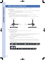
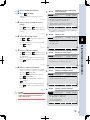
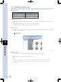
About system configuration
About system configuration
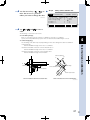
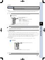
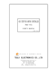
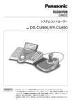
To use this system, it is necessary that the robot axis configuration is set as follows.
■ ■ For SCARA robot
The standard coordinates of the SCARA robot need to be set so that the "Y plus" direction is 90 degrees counterclockwise
to the "X plus" direction as shown in the figure below.
Additionally, it is necessary that the "R plus" direction is set to the counterclockwise rotation.
■ ■ For Cartesian robot
The axis configuration of the Cartesian robot needs to be set so that the Y-axis plus direction is 90 degrees
counterclockwise to the X-axis plus direction as shown in the figure below.
Additionally, for the robot with the R-axis, it is necessary that the R-axis plus direction is set to the counterclockwise
rotation.
Y-axis plus direction
Y-axis plus direction
X-axis
plus direction
X-axis
plus direction
R-axis
plus direction
R-axis
plus direction
Connectable axis configuration
Non-connectable axis configuration
63001-T7-00
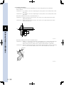
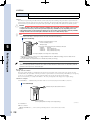
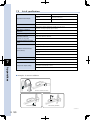
■ ■ Connectable image sensor
This system applies only to an image sensor that satisfies the specifications shown below.
● Communication method
RS-232C or Ethernet
* When connecting through the Ethernet, it is necessary to install the Ethernet network board in the robot controller.
Additionally, when connecting through the Ethernet, the robot controller functions as a server.
Therefore, it is necessary that the image sensor operates as a client.
● Image capturing trigger
The image sensor can be controlled by sending and receiving a command character string.
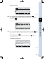
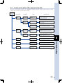
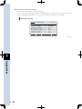
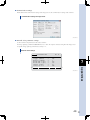
● Output setting
The response character string to the image capturing command should be returned and comma separated values of
the response character string, the number of detections, and X and Y coordinates and angle of the image captured
workpiece can be output.
* A delimiter can also be used for the character after the response character string.
2
Response
character
string
,
Response
character
string
CR
Number of
detections
,
Number of
detections
X (0)
,
,
X (0)
Y (0)
,
,
Y (0)
Angle (0)
,
Angle (0)
,
•••
,
,
•••
X (n)
,
,
X (n)
Y (n)
,
,
Y (n)
Angle (n)
,
Angle (n)
CR
CR
Safety precautions
Before using this product, thoroughly read this manual and related manuals, and operate the product in a
correct manner while carefully checking the safety.
The precautions stated in this manual relate to only this product. To ensure the safety of the user’s whole
system that includes this product, please take appropriate safety measures as required by the user’s individual
system.
This manual uses the following safety alert symbols and signal words to provide safety instructions that must
be observed and to describe handling precautions, prohibited actions, and instructions. Make sure that you
understand the meaning of each symbol and signal word, and then read this manual.
c
n
CAUTION
This indicates a potentially hazardous situation which, if not avoided, could result in minor or moderate injury, or
physical damage to the equipment.
NOTE
Explains the key point in the operation in a simple and clear manner.
The instructions stated even in "CAUTION" may lead to serious results depending on the conditions. In any
case, the instructions include important contents. So, be sure to strictly observe the instructions.
Please store this manual in a place where all concerned personnel can refer to it immediately and deliver it to
the final user.
■ ■ Design precautions
c
CAUTION
When the program execution stops halfway, the program executes the command that has been stopped again.
For example, carefully check the re-execution of the program when using the arch motion of the MOVE
command, relative movement commands, such as MOVEI command or DRIVEI command, or the
communication command of the SEND command.
3
Safety precautions
Be sure to read the safety precautions shown below before use.
Warranty
Warranty
For information on the warranty period and terms, please contact our distributor where you purchased the
product.
■ ■ This warranty does not cover any failure caused by:
1.Installation, wiring, connection to other control devices, operating methods, inspection or maintenance that does not
comply with industry standards or instructions specified in the YAMAHA manual;
2.Usage that exceeded the specifications or standard performance shown in the YAMAHA manual;
3.Product usage other than intended by YAMAHA;
4.Storage, operating conditions and utilities that are outside the range specified in the manual;
5.Damage due to improper shipping or shipping methods;
6.Accident or collision damage;
7.Installation of other than genuine YAMAHA parts and/or accessories;
8.Modification to original parts or modifications not conforming to standard specifications designated by YAMAHA,
including customizing performed by YAMAHA in compliance with distributor or customer requests;
9.Pollution, salt damage, condensation;
10.Fires or natural disasters such as earthquakes, tsunamis, lightning strikes, wind and flood damage, etc;
11.Breakdown due to causes other than the above that are not the fault or responsibility of YAMAHA;
■ ■ The following cases are not covered under the warranty:
1.Products whose serial number or production date (month & year) cannot be verified.
2.Changes in software or internal data such as programs or points that were created or changed by the customer.
3.Products whose trouble cannot be reproduced or identified by YAMAHA.
4.Products utilized, for example, in radiological equipment, biological test equipment applications or for other purposes
whose warranty repairs are judged as hazardous by YAMAHA.
THE WARRANTY STATED HEREIN PROVIDED BY YAMAHA ONLY COVERS DEFECTS IN PRODUCTS
AND PARTS SOLD BY YAMAHA TO DISTRIBUTORS UNDER THIS AGREEMENT. ANY AND ALL OTHER
WARRANTIES OR LIABILITIES, EXPRESS OR IMPLIED, INCLUDING BUT NOT LIMITED TO ANY IMPLIED
WARRANTIES OF MERCHANTABILITY OR FITNESS FOR A PARTICULAR PURPOSE ARE HEREBY EXPRESSLY
DISCLAIMED BY YAMAHA. MOREOVER, YAMAHA SHALL NOT BE HELD RESPONSIBLE FOR CONSEQUENT
OR INDIRECT DAMAGES IN ANY MANNER RELATING TO THE PRODUCT.
This manual does not serve as a guarantee of any industrial property rights or any other rights and
does not grant a license in any form. Please acknowledge that we bear no liability whatsoever for
any problems involving industrial property rights which may arise from the contents of this manual.
4
Ver.1.01_201209
Constructing a system
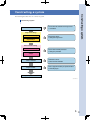
Constructing a system
The following describes how to construct a system.
Constructing a system
Connections
Connect the robot controller and image sensor.
1 Connections
Image sensor settings
Communication settings
Set the image sensor.
2 Setting the image sensor
Output settings
Robot controller settings
Communication settings
Set the robot controller parameters.
3 Setting the parameters
External vision parameter
settings
Camera calibration
Program creation
Calibrate the camera.
4 External vision calibration
Create a program necessary to operate the robot.
5 Robot languages
System operation check
63002-T7-00
5
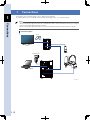
1. Connections
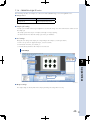
1
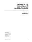
Connect the robot controller, image sensor, and personal computer.
For details about how to install the robot controller and image sensor, see relevant manuals.
Connections
MEMO
Connect the controller and personal computer through the Ethernet or RS-232C.
When connecting through the RS-232C, the communication cable connection destination needs to be changed
between the program editing and robot operation.
When connecting through the Ethernet, it is necessary to install the Ethernet network board in the controller.
Connection diagram
Mouse
Monitor
External vision
Camera
Programming box
MOTOR
PWR
SRV
XM
OP.1
OP.3
OP.2
OP.4
RPB
ERR
RCX240
ROB
I/O
XY
YM
BATT
XY
SEL
COM
ROB
I/O
Personal computer
Robot
ZR
ZM
BATT
ZR
STD.DIO
SAFETY
RGEN
P
N
L
RM
ACIN
N
L1
N1
EXT.E-STOP
PIN13−14
RCX240
63003-T7-00
6
2. Setting the image sensor
2.1
Communication settings
Match the communication settings of the image sensor to those of the robot controller.
For details about how to make the settings, see the manual for image sensor.
2
TIP
When connecting through the Ethernet, the robot controller functions as a server.
Therefore, it is necessary that the image sensor operates as a client.
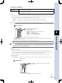
Coordinate settings
Setting the image sensor
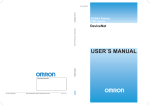
2.2
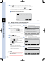
Set the image sensor origin, X and Y coordinates, and angle direction as shown in the figure below.
Setting the camera coordinates and X and Y coordinates
Origin (0, 0)
X
Y
Angle
Camera coordinates
63004-T7-00
2.3
Output settings
The image captured results of the image sensor are output.
• Output items
Item name
Description
Response character string
Response character string of the image sensor to the image capturing command
Number of detections
Number of workpieces detected during image capturing
X (n)
X-coordinate value of the detected workpiece (n) in the camera coordinate system (Unit: pix)
Y (n)
Y-coordinate value of the detected workpiece (n) in the camera coordinate system (Unit: pix)
Angle (n)
Angle of the detected workpiece in the camera coordinate system (Unit: °)
• Other symbols
Data separator
Comma ","
Delimiter
CR or CR/LF
7
• Format
Output comma separated data in any of the formats shown below.
2
Response
character
string
,
Response
character
string
CR
Number of
detections
,
Number of
detections
X (0)
Setting the image sensor
,
,
X (0)
Y (0)
,
,
Y (0)
Angle (0)
,
Angle (0)
,
•••
,
,
•••
X (n)
,
,
X (n)
Y (n)
,
,
Y (n)
Angle (n)
,
Angle (n)
CR
CR
Separate each data by a comma.
TIP
The response character string may vary depending on the image sensor.
Either a comma or delimiter can be used only for the data separator after the response character string.
Be sure to output the workpiece position information (X, Y, and angle) for the number of workpiece detections.
Set each data so that it becomes a character string containing less than 20 characters.
■ ■ Output example (The number of workpiece detections is 2.)
Manufacturer
Model name
Output example
CV-5000
T1,02,+00498.777,+00365.239,+155.096,+00434.443,+00267.915,-027.088
CV-X100
T1
0002,+00268.465,+00150.117,-00009.146,+00224.879,+00258.308,-00009.127
OMRON
FZ4
OK
0002,+00268.465,+00150.117,-00009.146,+00224.879,+00258.308,-00009.127
COGNEX
In-Sight®
1
2,315.667,126.415,0.717,128.363,481.136,1.637
KEYENCE
TIP
For details about output settings, see "7.1 Examples of controller and image sensor connections".
8
3. Setting the parameters
3.1
Communication settings
Match the communication settings of the robot controller to those of the image sensor.
For details about communication settings, see the RCX240 User's Manual.
3.2
External vision parameter settings
Set the external vision parameters according to the specifications of the image sensor to be connected.
3
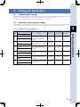
3.2.1 External vision parameter list
Name
Meaning
Input range
Initial value
Unit
Set the image capturing command
that is sent to the image sensor
when executing the EXSEARCH
command.
0 to 8
characters
-
-
Set the response character string
from the image sensor to the image
capturing command.
0 to 8
characters
-
-
Set the camera resolution in the
X-axis direction of the image sensor
to be used.
0 to 10000
640
[ pix ]
Set the camera resolution in the
Y-axis direction of the image sensor
to be used.
0 to 10000
480
[ pix ]
Set a period of the timeout time
during execution of the EXSEARCH
command.
0 to 600
100
[×100ms]
CMU/ETH
CMU
-
Programming box display
Trigger character string
1
Trigger Command
Response character string
2
Response Command
External vision resolution X
3
EX Cam FOV X
External vision resolution Y
4
EX Cam FOV Y
Search timeout
5
TimeOut
Communication port
6
Connection Port
Set the port used to communicate
with the image sensor.
9
Setting the parameters
No.
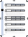
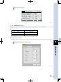
3.2.2 External vision parameter details
No.1
Input range
Initial value
Unit
0 to 8 characters
-
-
Trigger character string
Function
Sets the image capturing command that is sent to the image sensor when executing the EXSEARCH command.
Description
When executing the EXSEARCH command, the character string set by this parameter is sent to the image sensor.
Set the image capturing command of the image sensor.
Up to 8 characters can be set for this character string. Additionally, a blank character cannot be used.
3
No.2
Input range
Initial value
Unit
0 to 8 characters
-
-
Response character string
Setting the parameters
Function
Sets the response character string from the image sensor to the image capturing command.
Description
When sending the image capturing command to the image sensor, the response is returned from the image sensor.
Set the character string that is sent from the image sensor when the image sensor accepts the image capturing command
successfully.
If a character string other than that set by this command is sent from the image sensor, the search error is given.
Up to 8 characters can be set for this character string. Additionally, a blank character cannot be used.
No.3
No.4
Input range
Initial value
Unit
0 to 10000
640
[ pix ]
Input range
Initial value
Unit
0 to 10000
480
[ pix ]
External vision resolution X
External vision resolution Y
Function
Sets the camera resolutions in the X- and Y-axis directions of the image sensor to be used.
Description
Set the camera resolutions in the X- and Y-axis directions of the image sensor to be connected to the robot controller.
The settable range is 0 to 10000 [pix].
No.5
Input range
Initial value
Unit
0 to 600
100
[100 ms]
Search timeout
Function
Sets the timeout time during execution of the EXSEARCH command.
Description
If the response is not returned from the image sensor within the set period of time after executing the EXSEARCH
command, the timeout error is given. When the set value is 0, the search timeout process is not performed.
Set an appropriate value by considering the image capturing time of the image sensor.
No.6
Input range
Initial value
Unit
CMU/ETH
CMU
-
Communication port
Function
Sets the port used to communicate with the image sensor.
Description
When connecting the image sensor through the RS-232C, specify "CMU". When connecting through the Ethernet, specify
"ETH".
10
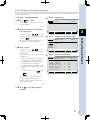
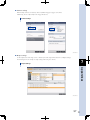
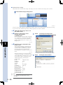
3.2.3 Editing an external vision parameter
This section describes how to edit parameters related to the external vision. To edit external vision parameters,
use the programming box.
1 Select "SYSTEM>OPTION".
(EX CAM).
2 Press
Step 2
The setting items related to the external
vision will appear.
Option setting
SYSTEM>OPTION V10.72
64001-T7-00
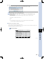
3 Select an external vision number
you want to edit.
Use the cursor keys (
POS.OUT SERVISE SIO W.CARRY EX CAM
/
) to select a
desired number from EXCAM1 to EXCAM4,
Selecting an external vision number
(EDIT).
When the external vision parameter has
already been set, "SET" is displayed.
64002-T7-00
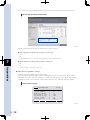
4 Enter a value.
Use the cursor keys (
/
) to move
the cursor to an item, in which you want to
enter a value.
Enter a character string or value, and press
the ENTER key.
SYSTEM>OPTION>EX CAM V10.72
EX Vision Camera
EXCAM1 = SET
EXCAM2 = EXCAM3 = EXCAM4 = EDIT Step 4
Setting the external vision
• Values you can enter are 0 to 9 and A to Z.
SYSTEM>OPTION>EX CAM
• For Trigger Command and Response
Command, enter a character string
containing 8 or less characters.
EX Vision Camera PRM : EXCAM2 Trigger Command = T1
Response Command = T1
EX Cam FOV X [pix] = 640
EX Cam FOV Y [pix] = 480
TimeOut [100ms] = 100
Connection Port = CMU
• For EX Cam FOV X, EX Cam FOV Y, and
TimeOut, enter a value within its input
range.
• For Connection Port, select
or
*
V10.72
(CMU)
(ETH).
For Connection Port, the value is set
when pressing the function key.
Repeat operation steps shown above to
enter values in all items.
64003-T7-00
5 Press
to exit the parameter
editing.
11
Setting the parameters
and press
Step 3
3
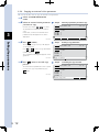
3.2.4 Copying an external vision parameter
This section describes how to copy an external vision parameter.
1 Select "SYSTEM>OPTION>EX
CAM".
2 Select an external vision parameter
you want to copy.
Use the cursor keys (
/
) to select
an external vision parameter you want to
copy.
In the items, for which the external vision
parameter has already been set, "SET" is
displayed.
3
64004-T7-00
Setting the parameters
3 Press
to
to select a copy destination
number, and press
.
The confirmation message will appear on the
guide line.
64005-T7-00
4 Press
(YES) to start the copy
process.
The external vision parameter is then copied.
If you do not copy the parameter, press
(NO).
64006-T7-00
Selecting a parameter you want to copy
SYSTEM>OPTION>EX CAM V10.72
EX Vision Camera
EXCAM1 = SET
EXCAM2 = EXCAM3 = EXCAM4 = EDIT
Step 3
(COPY).
The message, "Copy to [1-4]>", will appear
on the guide line.
Press
Step 2
Entering a copy destination
SYSTEM>OPTION>EX CAM V10.72
EX Vision Camera
EXCAM1 = SET
EXCAM2 = EXCAM3 = EXCAM4 = Copy to[1ー4]>
Step 4
Confirming the copy execution
SYSTEM>OPTION>EX CAM V10.72
EX Vision Camera
EXCAM1 = SET
EXCAM2 = EXCAM3 = EXCAM4 = (1ー>2)Copy OK? YES NO
12
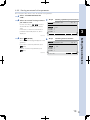
3.2.5 Erasing an external vision parameter
This section describes how to erase an external vision parameter.
1 Select "SYSTEM>OPTION>EX
CAM".
2 Select an external vision parameter
you want to erase.
Use the cursor keys (
Step 2
Selecting a parameter you want to erase
SYSTEM>OPTION>EX CAM V10.72
/
) to select
an external vision parameter you want to
erase.
In the items, for which the external vision
parameter has already been set, "SET" is
displayed.
EX Vision Camera
EXCAM1 = SET
EXCAM2 = EXCAM3 = EXCAM4 = 3
EDIT
64007-T7-00
Step 3
(ERASE).
The confirmation message will appear on the
guide line.
If you want to erase the parameter, press
(YES).
If you do not erase the parameter, press
(NO).
64008-T7-00
Confirming the erase execution
SYSTEM>OPTION>EX CAM V10.72
EX Vision Camera
EXCAM1 = SET
EXCAM2 = EXCAM3 = EXCAM4 = Erase OK? YES NO
13
Setting the parameters
3 Press
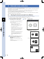
4. External vision calibration
This section describes how to calibrate the external vision.
The calibration is a work necessary to match the coordinates (camera coordinates) of the image captured by
the camera to the robot coordinates.
The calibration of the external vision is required when constructing a system for the first time or when the
positional relationship between the camera and robot changes (the camera deviates).
Up to four external vision calibration data can be stored.
When the distance between the workpiece and camera is different or when multiple cameras are installed,
calibrate the external vision for each camera.
4.1
Executing the interactive external vision calibration
This section describes how to make the settings using the interactive external vision calibration.
The following describes the setting procedures using KEYENCE "CV-X100 series".
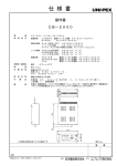
4
1 Put the calibration marks within
the field-of-view of the camera.
Step 1
Calibration marks
64009-T7-00
External vision calibration
In this example, the circular mark and
square mark are determined to mark 0 and
mark 1, respectively.
*
Make the distance between the
calibration mark and camera identical
with that at system startup.
*
Do not move the mark until the end of
the program execution.
*
Arrange the marks so that they are as far
away from each other as possible. If the
marks are arranged in the near distance,
the coordinate conversion accuracy
may decrease.
Additionally, do not arrange the marks at
four corners of the field-of-view of the
camera. The mark image may be
distorted depending on the lens to be
used.
Examples of calibration mark arrangements
Correct example
2 Set the tool of the image sensor so
that the calibration marks are
detected.
Incorrect example
Set the tool so that mark 0 and mark 1 are
detected.
For details about how to set the tool, see the
manual for image sensor.
Marks are arranged in the near distance.
Marks are arranged at the corners of
the field-of-view of the camera.
14
3 Select "MANUAL>VISION".
4 Press
Step 4
(EX WIZ).
Make the interactive setting of the camera
calibration.
64010-T7-00
5 Select a robot, to which the camera
belongs.
Press
(MAIN) or
(SUB) to select a
robot, to which the camera to be calibrated
belongs.
64011-T7-00
Starting the interactive setting of the
camera calibration
MANUAL>VISION 20%[MG] [S0H0X]
Select function
F1:Camera Calibration Wizard
F2:Edit Camera Calibration
F3:EX Camera Calibration Wizard
F4:Edit EX Camera Calibration
CAMWIZ CAMEDT EX WIZ EX EDT
* If the iVY board is not installed in the robot controller, [CAMWIZ] (F1)
and [CAMEDT] (F2) are not displayed.
Step 5
Selecting a robot
6 Select an external vision.
Use
to
to select an external vision
you want to calibrate.
To return the operation to the previous step,
press
(<<PREV).
MANUAL>VISION>EX WIZ 20%[MG] [S0H0X]
Select robot to which camera belongs
F1:Main robot
F2:Sub robot
MAIN SUB
7 Select a calibration number.
Use
(CALIB0) to
(CALIB3) to select
a number, into which the calibration settings
are registered.
To return the operation to the previous step,
press
(<<PREV). (The operation returns
Step 6
Selecting an external vision
MANUAL>VISION>EX WIZ 20%[MG] [S0H0X]
Select EX Camera to Calibrate
F1ー4:EX Vision Camrera No. 1ー4
to Step 6.)
64047-T7-00
8 Select a camera orientation.
EXCAM1 EXCAM2 EXCAM3 EXCAM4 <<PREV
When the camera is installed on the SCARA
robot or the Y-axis or Z-axis of the Cartesian
axes, press
Selecting a calibration number
(2ND ARM).
When using the downward fixed camera,
press
Step 7
(DOWNWRD).
When using the upward fixed camera, press
MANUAL>VISION>EX WIZ 20%[MG] [S0H0X]
Select calibration number
F1ー4:Calibration No.0ー3
(UPWRD).
To return the operation to the previous step,
press
(<<PREV). (The operation returns
CALIB0 CALIB1 CALIB2 CALIB3 <<PREV
to Step 7.)
64013-T7-00
c
CAUTION
When installing the camera on the robot, do not
install it on the rotating part, such as the R-axis
shaft or on the X-axis.
Step 8
Selecting a camera orientation
MANUAL>VISION>EX WIZ 20%[MG] [S0H0X]
Select camera orientation
F1:Mounted on 2nd arm
F3:Fixed downward
F4:Fixed upward
2ND ARM DOWNWRD UPWRD <<PREV
15
External vision calibration
64012-T7-00
4
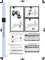
Examples of camera installations
When the camera is installed on the Y-axis or Z-axis of the
When the camera is secured to the non-movable part and it is
robot, select
faced downward, select
(2ND ARM).
(DOWNWRD).
Camera
Camera
When the camera is secured to the non-movable part and it is
4
faced upward, select
(UPWRD).
External vision calibration
Camera
Camera
63005-T7-00
9 Check the setting contents.
Step 9
The setting contents until Step 8 will appear.
When the setting contents have no problem
and you start the calibration subsequently,
press
(START).
To make the settings again, press
(RESET). (You need to make the settings
again from Step 5.)
To return the operation to the previous step,
press
Checking the setting contents
MANUAL>VISION>EX WIZ 20%[MG] [S0H0X]
Confirm the setting
MAIN/EXCAM1/CALIB0/DOWNWRD
F1:Confirmed. Start calibration
F2:Reset the setting
START RESET <<PREV
(<<PREV). (The operation returns
to Step 8.)
64017-T7-00
0 Arrange two calibration marks
within the field-of-view of the
camera.
Check with the monitor of the image sensor
that the calibration marks exist within the
field-of-view, and then press the ENTER key
on the programming box.
n
NOTE
After pressing the ENTER key, do not move the
robot until the operation stated in Step 11 is
completed. Otherwise, the calibration data may
not be obtained correctly.
64014-T7-00
16
Step 10
Arranging the calibration marks within
the field-of-view of the camera
MANUAL>VISION>EX WIZ 20%[MG] [S0H0X]
x y z r
Place 2 marks within FOV and press
ENTER key
[POS] 0.00 0.00 0.00 0.00
VEL+ VELー
q Set the camera coordinates of the fiducial marks.
Capture the images of fiducial marks 0 and 1, and enter the measurement values of the fiducial marks
obtained from the image sensor.
At this time, enter the values using "0 to 9" and ".".
After entering the values, press the ENTER key to set them.
After you have entered all values, press
(SET).
Setting the camera coordinates of fiducial mark 0
4
Input Two Marks position [pix]
And Press F1:SET
Mark0 X[pix] = 474.88
Y[pix] = 596.15
Mark1 X[pix] = 0.00
Y[pix] = 0.00
SET
64015-T7-00
17
External vision calibration
MANUAL>VISION>EX WIZ 20%[MG] [S0H0X]
Setting the camera coordinates of fiducial mark 1
4
MANUAL>VISION>EX WIZ 20%[MG] [S0H0X]
External vision calibration
Input Two Marks position [pix]
And Press F1:SET
Mark0 X[pix] = 486.13
Y[pix] = 593.69
Mark1 X[pix] = 1123.43
Y[pix] = 584.26
SET
64016-T7-00
w Move the target robot to the fiducial mark 0 position, and press
Move the tip of the target robot to the fiducial mark 0 position, and press
.
.
To move the tip of the target robot, use the JOG key or press the emergency stop button on the
programming box and manually move it in the emergency stop state.
When pressing
w
n
, the robot tip position (XY coordinates) is then set to Mrk0.
WARNING
• When moving the robot with the JOG key, the robot operates. So, do not enter the robot movement range to prevent any hazard.
• When moving the robot manually, be sure to put the operation in the emergency stop state by pressing the emergency stop button on the programming box.
The servo does not turn on from a view point of hardware in the emergency stop state.
NOTE
• When teaching the robot tip position coordinates in fiducial mark 0 (Mrk0) in pulses, they are converted into those in mm during setting.
• To change the manual movement speed when moving the robot with the JOG key, use
(VEL-),
(VEL++), or
(VEL+),
(VEL--).
• For the robot with the rotation axis, such as the SCARA robot, the rotation center when turning the rotation axis becomes the robot tip. When performing the calibration with the tool attached, set the hand so that the tool tip becomes the rotation center.
18
Moving to fiducial mark 0
MANUAL>VISION>EX WIZ 20%[MG] [S0H0X]
x y z r
Move to Mark 0 and press ENTER key
Mrk0=
Mrk1=
[POS] 0.00 0.00 0.00 0.00
VEL+ VELー
64018-T7-00
e Move the target robot to the fiducial mark 1 position, and press
.
In the same manner as described in Step 12, move the tip of the target robot to the fiducial mark 1
position, and press
4
.
Moving to fiducial mark 1
[POS] 200.00 100.00 30.00 0.00
VEL+ VELー
64019-T7-00
r Make sure that two fiducial mark positions have no problem, and press
(OK).
Check that the robot coordinate data of fiducial marks 0 and 1 you have set in Step 12 and Step 13 is
correct.
When no problem is found, press
(OK).
When teaching the robot coordinate data of the fiducial marks again, press
(REDO). (The
operation returns to Step 12.)
Checking the fiducial mark positions
MANUAL>VISION>EX WIZ 20%[MG] [S0H0X]
x y z r
Confirm positions of 2 marks
Mrk0= 200.00 100.00
Mrk1= 250.00 150.00
[POS] 250.00 150.00 30.00 0.00
OK REDO
64020-T7-00
19
External vision calibration
MANUAL>VISION>EX WIZ 20%[MG] [S0H0X]
x y z r
Move to Mark 1 and press ENTER key
Mrk0= 200.00 100.00
Mrk1=
t Press
(YES) to register the camera calibration settings.
The message, "Set OK?", will appear on the bottom line of the programming box.
To register the camera calibration settings, press
(YES).
To cancel the registration of the camera calibration settings, press
(NO).
Registering the camera calibration settings
MANUAL>VISION>EX WIZ 20%[MG] [S0H0X]
x y z r
4
Set OK? YES NO
64021-T7-00
4.2
Editing external vision calibration data
External vision calibration
This section describes how to edit external vision calibration data.
1 Select "MANUAL>VISION>EX
EDT".
64022-T7-00
2 Select a calibration number.
Use the cursor keys (
/
) to select a
calibration number you want to edit. In the
items, for which the camera calibration has
already been set, "SET" is displayed.
64023-T7-00
3 Press
When the camera is installed on the SCARA
robot or the Y-axis or Z-axis of the Cartesian
(2ND ARM).
When using the downward fixed camera,
(DOWNWRD).
When using the upward fixed camera, press
(UPWRD).
When the camera orientation has already
been set, the current setting state is
displayed at the right end of the 3rd line on
the screen.
When selecting the camera orientation, the
detail edit screen will appear.
64024-T7-00
c
20
MANUAL>VISION 20%[MG] [S0H0X]
Select function
F1:Camera Calibration Wizard
F2:Edit Camera Calibration
F3:EX Camera Calibration Wizard
F4:Edit EX Camera Calibration
CAMWIZ CAMEDT EX WIZ EX EDT
Step 2
4 Select a camera orientation.
press
Editing calibration data
* If the iVY board is not installed in the robot controller, [CAMWIZ] (F1)
and [CAMEDT] (F2) are not displayed.
(EDIT).
axes, press
Step 1
CAUTION
When installing the camera on the robot, do not
install it on the rotating part, such as the R-axis
shaft or on the X-axis.
Selecting a calibration number
MANUAL>VISION>EX EDT 20%[MG] [S0H0X]
EX Vision Camera
CALIB0 = SET
CALIB1 = CALIB2 = CALIB3 = EDIT
Step 4
Selecting a camera orientation
MANUAL>VISION>EX EDT 20%[MG] [S0H0X]
Camera/Calib : EXCAM/CALIB0 [2ND ARM]
Select camera orientation
2ND ARM DOWNWRD UPWRD
5 Use the cursor keys (
/
) to
move the cursor to a position
where you want to change the data.
64025-T7-00
6 Use
to
, and
Step 5
Editing camera calibration data
MANUAL>VISION>EX EDT 20%[MG] [S0H0X]
Camera/Calib : EXCAM/CALIB0 [2ND ARM]
Scale Ratio[mm/pix] = 0.0000
Camera Angle[deg] = 0.0000
Parameter 1 = 0.00
Parameter 2 = 0.00
to enter a
value.
The meaning of each item is as follows.
● Scale Ratio [mm/pix]
Ratio of conversion from the camera coordinates to the robot coordinates
Specify how many millimeters per pixel. The set value must be 0.0001mm/pix or more.
4
● Camera Angle [deg]
The meaning of this item may vary depending on the robot setting and camera orientation.
<Fixed camera>
Camera installation angle to the robot coordinates
<Camera is installed on the arm of the Cartesian robot.>
Camera installation angle to the robot coordinates
<Camera is installed on the arm of the SCARA robot.>
Camera installation angle to the 2nd arm
Camera coordinates
Y+
X+
X+
Camera angle
Y+
R-axis rotation center
Camera angle
Camera coordinates
X+
2nd arm rotation center
Y+
Camera is installed on the arm of the Cartesian robot.
Camera is installed on the arm of the SCARA robot.
63006-T7-00
21
External vision calibration
● Parameter 1/Parameter 2
The meaning of this item may vary depending on the robot setting and camera orientation.
<Fixed camera>
Parameter 1 = X -coordinate of the robot expressing the center position of the camera field-of-view
(Unit: mm)
Parameter 2 = Y-coordinate of the robot expressing the center position of the camera field-of-view
(Unit: mm)
<Camera is installed on the arm of the Cartesian robot.>
Parameter 1 = Offset amount from the robot tip to the center of the camera field-of-view in the
X-direction (Unit: mm)
Parameter 2 = Offset amount from the robot tip to the center of the camera field-of-view in the
Y-direction (Unit: mm)
4
X
External vision calibration
Y
63007-T7-00
<Camera is installed on the arm of the SCARA robot.>
Parameter 1 = Number of offset pulses from the line connecting the root of the 2nd arm and the tip
to the line connecting the root of the 2nd arm and the center of the camera
field-of-view. Specify "+" value for the counterclockwise direction. (Unit: Pulse)
Parameter 2 = Difference between the length of the 2nd arm and the length of the line connecting
the root of the 2nd arm and the center of the camera field-of-view. (Unit: mm)
Parameter 2
Parameter 1
63008-T7-00
22
4.3
Copying external vision calibration data
This section describes how to copy external vision calibration data.
1 Select "MANUAL>VISION>EX
Step 1
EDT".
64026-T7-00
2 Select calibration data you want to
copy.
Use the cursor keys (
/
) to select
calibration data you want to copy.
In the items, for which the calibration data
has already been set, "SET" is displayed.
64027-T7-00
3
Press
to
to select a copy destination
.
The confirmation message will appear on the
guide line.
64028-T7-00
4 Press
Select function
F1:Camera Calibration Wizard
F2:Edit Camera Calibration
F3:EX Camera Calibration Wizard
F4:Edit EX Camera Calibration
CAMWIZ CAMEDT EX WIZ EX EDT
(YES) to start the copy
process.
(NO).
64029-T7-00
Selecting calibration data you want to copy
4
MANUAL>VISION>EX EDT 20%[MG] [S0H0X]
EX Vision Camera
CALIB0 = SET
CALIB1 = CALIB2 = CALIB3 = EDIT
Step 3
The external vision calibration data is then
copied.
If you do not copy the data, press
Step 2
Entering a copy destination
MANUAL>VISION>EX EDT 20%[MG] [S0H0X]
EX Vision Camera
CALIB0 = SET
CALIB1 = CALIB2 = CALIB3 = Copy to[0ー3]>
Step 4
Confirming the copy execution
MANUAL>VISION>EX EDT 20%[MG] [S0H0X]
EX Vision Camera
CALIB0 = SET
CALIB1 = CALIB2 = CALIB3 = (0ー>1)Copy OK? YES NO
23
External vision calibration
number, and press
MANUAL>VISION 20%[MG] [S0H0X]
* If the iVY board is not installed in the robot controller, [CAMWIZ] (F1) and
[CAMEDT] (F2) are not displayed.
(COPY).
The message, "Copy to [0-3]>", will appear
on the guide line.
Press
Copying external vision calibration data
4.4
Erasing external vision calibration data
This section describes how to erase external vision calibration data.
1 Select "MANUAL>VISION>EX
EDT".
64030-T7-00
2 Select calibration data you want to
erase.
Use the cursor keys (
/
) to select
calibration data you want to erase.
In the items, for which the calibration data
has already been set, "SET" is displayed.
Step 1
Copying external vision calibration data
MANUAL>VISION 20%[MG] [S0H0X]
Select function
F1:Camera Calibration Wizard
F2:Edit Camera Calibration
F3:EX Camera Calibration Wizard
F4:Edit EX Camera Calibration
CAMWIZ CAMEDT EX WIZ EX EDT
64031-T7-00
4
3
Press
* If the iVY board is not installed in the robot controller, [CAMWIZ] (F1)
and [CAMEDT] (F2) are not displayed.
(ERASE).
The confirmation message will appear on the
guide line.
Step 2
Selecting calibration data you want to erase
External vision calibration
If you want to erase the data, press
MANUAL>VISION>EX EDT 20%[MG] [S0H0X]
(YES).
EX Vision Camera
CALIB0 = SET
CALIB1 = CALIB2 = CALIB3 = If you do not erase the data, press
(NO).
64032-T7-00
EDIT
Step 3
Confirming the erase execution
MANUAL>VISION>EX EDT 20%[MG] [S0H0X]
EX Vision Camera
CALIB0 = SET
CALIB1 = CALIB2 = CALIB3 = Erase OK? YES NO
24
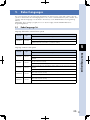
5. Robot languages
This section describes the robot languages dedicated to the external vision system and common to the iVY
system. For details about the robot language basic rules, such as command statement syntax, variable, and
constant, and robot languages not described in this manual, see the YAMAHA RCX Series Programming
Manual.
Additionally, when creating a program, be sure to also thoroughly read the YAMAHA RCX Series
Programming Manual.
5.1
Robot language list
Language dedicated to external vision system
Function
Language
Type
Syntax
Performs the image capturing of the image sensor to search for workpiece.
EXSEARCH
Command
EXSEARCH <External vision number> [, <Calibration number>]
5
Language common to iVY system
Function
Language
Type
Acquires the number of detected workpieces after searching.
VGETCNT
Function
VGETCNT
VGETPIX
Function
Acquires the pixel data of the specified array element number from the search result array in the
point data format after searching.
VGETPIX( <Array element number> )
VGETPOS
Function
Acquires the point data of the specified array element number from the search result array after
searching.
VGETPOS( <Array element number> )
VGETPOSX
Function
Acquires the X-coordinate value of the point data of the specified array element number from the
search result array after searching.
VGETPOSX( <Array element number> )
VGETPOSY
Function
Acquires the Y-coordinate value of the point data of the specified array element number from the
search result array after searching.
VGETPOSY( <Array element number> )
25
Robot languages
Syntax
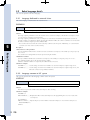
5.2
Robot language details
This section explains each robot language.
5.2.1 Language dedicated to external vision
This robot language is dedicated to the external vision.
E XSEARCH
EXSEARCH
EXSEARCH <External vision setting number> [, <Calibration number>]
Captures the images using the external vision to search for workpiece.
Function
The image capturing command is sent to the external vision to search for workpiece, and then this search process result
is received to store it into the search result array.
The image capturing command to be sent, received process result check, and communication port to be used are set
using the external vision parameters. When specifying the calibration number, the camera coordinates are converted into
the robot coordinates using the specified calibration data.
* The search results are stored into the search result array common to the iVY system. Additionally, "0" is stored into the
scale and score values of the search result array.
5
Description
<External vision setting number>
Robot languages
Specify a parameter number for the external vision to be used for the search process. The number you can specify is any
one of 1 to 4.
The external vision setting number can also be specified using the variable.
<Calibration number>
Specify a calibration number to be used for the search process. The number you can specify is any one of 0 to 3.
The calibration number can also be specified using the variable.
When the calibration number is not specified, the calibration data is not used.
Statement examples
EXSEARCH 1����������� Uses the settings of external vision number 1 to search for workpiece using the image sensor.
EXSEARCH 2,3�������� Uses the settings of external vision number 2 to search for workpiece using the image sensor, and
makes the correction using calibration number 3.
5.2.2 Language common to iVY system
This section explains the robot language common to the iVY system.
V GETCNT
VGETCNT
VGETCNT
Acquires the number of detected workpieces after searching.
Function
This function acquires the number of detected workpieces after searching.
Statement examples
EXSEARCH 1,2
PRINT VGETCNT��������� Outputs the number of detected workpieces to the programming box screen as a result of the
search process.
C%=VGETCNT-1
FOR A%=0 TO C%������ Repeats the process for the number of detected workpieces as a result of the search process.
PRINT VGETPOS(A%)
NEXT A%
26
V GETPIX
VGETPIX(<Array element number>)
VGETPIX
Acquires the pixel data of the specified array element number from the search result array after searching.
(The value is acquired in the point data format.)
Function
This function acquires the pixel data from the search result array after searching. The pixel data is acquired from the
specified array element of the search result array. The unit system of the pixel data to be acquired is pixel.
n
NOTE
• The search result array is an array that stores the search results after searching.
Search result array
No. 0
N o. 1
N o. 2
N o. 4
No.5
No.6
No.7
No.8
No.9
0
No.1
1
No.1
Information on detected workpiece is stored
• X- and Y-coordinate positions
• Workpiece angle
These results can be acquired using the commands shown below.
• VGETPIX
Pixel data
• VGETPOS
Robot coordinate data
• VGETPOSX
Robot coordinate data (X-axis)
• VGETPOSY
Robot coordinate data (Y-axis)
5
* The array list depends on the image sensor output settings.
• The point data to be acquired does not include any hand system flag.
Description
<Array element number>
This array element number is a number that specifies the array element of the search result array. Specify an array
element number, the pixel data of which you want to acquire from the search result array. The number you can specify is
any one of 0 to (VGETCNT-1). The array element number can also be specified using the variable.
The search result array is counted from number 0. The order of the array elements is a sequence that they are sorted by
the robot coordinates by means of the sorting method specified by VSETSORT. (When the calibration number is not
specified, this order becomes a sequence that the array elements are sorted by the pixel coordinates.)
Statement examples
P10=VGETPIX(0)������ Substitutes the pixel data of the 1st search result (array element number 0) into P10.
P10=VGETPIX(0)
Substitutes the point data stored here into P10.
N o. 0
N o. 2
N o. 3
N o. 4
Search result array
(The array list depends on the image sensor output settings.)
63010-T7-00
n
NOTE
It is not allowed to write like MOVE P,VGETPIX(0).
27
Robot languages
MEMO
The array is, for example, just like a cabinet. A name (array element number) is put on each drawer that stores
data. The same type data is stored into each drawer. In this manual, the drawer name is called "array element
number", but it may also be called "subscript".
V GETPOS
VGETPOS(<Array element number>)
VGETPOS
Acquires the point data of the specified array element number from the search result array after searching.
Function
This function acquires the point data from the search result array after searching. The point data is acquired from the
specified array element of the search result array. At this time, the Z-axis height of the robot during search execution is
acquired as Z-axis point data. The unit system of the point data to be acquired is mm (Cartesian coordinate system).
c
n
CAUTION
For the Z-axis data of the point data acquired by VGETPOS, the Z-axis height of the robot during search execution
is acquired. Therefore, the position of the point data acquired by VGETPOS may vary depending on the robot
position during search execution. When moving the robot to the position of the point data acquired by VGETPOS,
carefully check the robot movement path so that the Z-axis does not collide with any object.
NOTE
• The search result array is an array that stores the search results after searching.
Search result array
No. 0
No. 1
N o. 2
N o. 4
N o. 5
N o. 6
N o. 7
No. 8
N o. 9
0
No. 11
No. 1
5
Information on detected workpiece is stored
• X- and Y-coordinate positions
• Workpiece angle
These results can be acquired using the commands shown below.
• VGETPIX
Pixel data
• VGETPOS
Robot coordinate data
• VGETPOSX
Robot coordinate data (X-axis)
• VGETPOSY
Robot coordinate data (Y-axis)
Robot languages
* The array list depends on the image sensor output settings.
• When performing the search process using EXSEARCH without calibration settings, the error "20.80 : EX Vis calibration not set" may occur.
• The point data to be acquired does not include any hand system flag.
MEMO
The array is, for example, just like a cabinet. A name (array element number) is put on each drawer that stores
data. The same type data is stored into each drawer. In this manual, the drawer name is called "array element
number", but it may also be called "subscript".
Description
<Array element number>
This array element number is a number that specifies the array element of the search result array. Specify an array
element number, the point data of which you want to acquire from the search result array. The number you can specify
is any one of 0 to (VGETCNT-1). The array element number can also be specified using the variable.
The search result array is counted from number 0. The array list depends on the image sensor output settings.
Statement examples
P10=VGETPOS(0)���� Substitutes the point data of the 1st search result (array element number 0) into P10.
P10=VGETPOS(0)
Substitutes the point data stored here into P10.
N o. 0
N o. 2
No. 3
N o. 4
Search result array
(The array list depends on the image sensor output settings.)
63012-T7-00
C%=VGETCNT-1
FOR A%=0 TO C%
MOVE P,VGETPOS(A%)...... Moves to the point data positions of all search results in order.
NEXT A%
28
VGETPOSX/VGETPOSY
VGETPOSX(<Array element number>)
VGETPOSX
VGETPOSY
VGETPOSY(<Array element number>)
Acquires the X- or Y-coordinate position of the workpiece of the specified array element number from the
search result array after searching.
Function
This function acquires the X- or Y-coordinate position of the workpiece from the search result array after searching.
The X- or Y-coordinate position of the workpiece is acquired from the specified array element of the search result array.
The unit system of the data to be acquired is mm (Cartesian coordinate system).
VGETPOSX������ Acquires the X-coordinate position of the workpiece from the search result array.
VGETPOSY������ Acquires the Y-coordinate position of the workpiece from the search result array.
n
NOTE
• The search result array is an array that stores the search results after searching.
Search result array
Information on detected workpiece is stored
• X- and Y-coordinate positions
• Workpiece angle
5
These results can be acquired using the commands shown below.
• VGETPIX
Pixel data
• VGETPOS
Robot coordinate data
• VGETPOSX
Robot coordinate data (X-axis)
• VGETPOSY
Robot coordinate data (Y-axis)
* The array list depends on the image sensor output settings.
• When performing the search process using EXSEARCH without calibration settings, the error "20.80 : EX Vis calibration not set" may occur.
• The point data to be acquired does not include any hand system flag.
MEMO
The array is, for example, just like a cabinet. A name (array element number) is put on each drawer that stores
data. The same type data is stored into each drawer. In this manual, the drawer name is called "array element
number", but it may also be called "subscript".
Description
<Array element number>
This array element number is a number that specifies the array element of the search result array. Specify an array
element number, the data of which you want to acquire from the search result array. The number you can specify is any
one of 0 to (VGETCNT-1). The array element number can also be specified using the variable.
The search result array is counted from number 0. The array list depends on the image sensor output settings.
Statement examples
A=VGETPOSX(0)������ Substitutes the X-coordinate position of the workpiece of the 1st search result (array element
number 0) into A.
A=VGETPOSX(0)
N o. 0
N o. 2
N o. 3
N o. 4
Substitutes the X-coordinate position of the workpiece stored here
into variable A.
Search result array
(The array list depends on the image sensor output settings.)
63014-T7-00
29
Robot languages
N o. 0
N o. 1
N o. 2
N o. 4
N o. 5
N o. 6
N o. 7
N o. 8
N o. 9
0
No. 11
No. 1
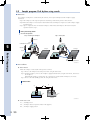
5.3
Sample program: Pick & place using search
■ ■ Over view
The workpiece on the pallet is searched for by the cameras, and it is picked and placed at the workpiece supply
destination.
Step 1:The workpieces on the respective pallets are alternately searched for by camera 1 and camera 2.
Step 2:When the workpiece is detected, the robot holds the detected workpiece and places it at the workpiece supply
destination (P20).
Step 3:Step 2 is repeated to move all detected workpieces. After all detected workpieces have been moved, the
operation returns to step 1.
Pick & place using search
Overview of operation
Step 1: Searching for workpiece
Step 2: Pick & place
Camera 2
Search
Downward fixed camera
5
Pallet 2
Pallet 2
Camera 1
Conveyor
Conveyor
Search
Robot languages
Pallet 1
Pallet 1
P20
Workpiece supply destination
63019-T7-00
■ ■ Preconditions
● Robot motion
When the workpiece is detected, the robot operates as follows.
Step 1:Moves to the workpiece detection position (P10) using the arch motion.
Step 2:Holds the workpiece, moves to the workpiece supply destination (P20) using the arch motion, and releases
the workpiece.
When multiple workpieces are detected, step 1 and step 2 are repeated until all workpieces are moved.
Step 3:Moves to the robot standby position (P1) using the arch motion.
Robot motion
(1)
(3)
P1
(2)
P10
Pallet
P20
Conveyor
63020-T7-00
● Points to be used
P1������� Standby position
P10����� Workpiece detection position (written in the program)
P20����� Workpiece supply position
30
● Input/output signals to be used
Output signal state
Contents of output signal
DO(20)
Workpiece pick & place instruction
1
0
Hold
Release
● Others
• It is preconditioned that each camera is set as shown below.
Fixing method
External vision setting
number
Calibration number
Communication
method
Camera 1
Downward
1
0
ETH
Camera 2
Downward
2
1
CMU
• The Z-axis height of the robot at the workpiece holding position should be 50.00mm.
• The workpiece detection settings and output settings should be made on each camera correctly.
• The camera calibration of each camera should be performed correctly.
5
Robot languages
31
■ ■ Sample program
*INIT:
・・・・・ Label definition (initial process)
OFFLINE CMU
・・・・・ Clears the buffer of the RS-232C port and changes the mode to the offline.
OFFLINE ETH
・・・・・ Clears the buffer of the Ethernet port and changes the mode to the offline.
DELAY 100
IF ETHSTS = 2 THEN
・・・・・ Checks the buffer state of the Ethernet port.
GOTO *INIT
・・・・・ Jumps to label *INIT if data remains in the buffer.
ENDIF
'
COUNT% = 0
・・・・・ Sets the initial value of the variable.
MOVE P,P1,Z=0.0
・・・・・ Moves to the standby position using the arch motion.
WAIT ARM
・・・・・ Waits for completion of the robot operation.
'
*MAIN:
・・・・・ Label definition (main routine)
EXSEARCH 1,0
・・・・・ Executes the search process of camera 1.
IF VGETCNT > 0 THEN ・・・・・ When workpiece is detected,
GOSUB *PICKPLACE ・・・・・ Jumps to label *PICKPLACE.
ELSE
PRINT "*** PALLET1: WORK NOT FOUND ***" ・・・・・Displays the message if no workpiece is detected.
ENDIF
'
MOVE P,P1,Z=0.0
・・・・・ Moves to the standby position using the arch motion.
WAIT ARM
・・・・・ Waits for completion of the robot operation.
'
EXSEARCH 2,1
・・・・・ Executes the search process of camera 2.
IF VGETCNT > 0 THEN ・・・・・ When workpiece is detected,
GOSUB *PICKPLACE ・・・・・ Jumps to label *PICKPLACE.
ELSE
・・・・・ If no workpiece is detected,
PRINT "*** PALLET2: WORK NOT FOUND ***" ・・・・・Displays the message.
ENDIF
'
MOVE P,P1,Z=0.0
・・・・・ Moves to the standby position using the arch motion.
WAIT ARM
・・・・・ Waits for completion of the robot operation.
'
COUNT% = COUNT% + 1 ・・・・・ Counts the search execution cycles.
IF COUNT% > 5 THEN
・・・・・ Search is repeated 5 times.
PRINT "*** PROGRAM END ***" ・・・・・Displays the message.
ONLINE CMU
・・・・・ Clears the buffer of the RS-232C port and changes the mode to the online.
ONLINE ETH
・・・・・ Clears the buffer of the Ethernet port and changes the mode to the online.
HALT
・・・・・ Exits the program.
ENDIF
・・・・・ If the number of search cycles is less than 5,
'
GOTO *MAIN
・・・・・ Jumps to label *MAIN and repeats the search.
'
*PICKPLACE:
・・・・・ Label definition (pick & place)
FOR I% = 0 TO VGETCNT -1 ・・・・・Repeats for the number of detected workpieces.
P10 = VGETPOS(I%) ・・・・・ Copies the workpiece detection position to P10.
LOCZ(P10) = 50.0
・・・・・ Sets the Z-axis position of P10 to 50.00mm.
MOVE P, P10, Z=0.0 ・・・・・ Moves to P10 using the arch motion.
DO(20) = 1
・・・・・ Holds the workpiece.
DELAY 100
・・・・・ Waits for 100ms.
'
MOVE P, P20, Z=0.0 ・・・・・ Moves to the workpiece supply position P20 using the arch motion.
DO(20) = 0
・・・・・ Releases the workpiece.
DELAY 100
・・・・・ Waits for 100ms.
NEXT
RETURN
・・・・・ Returns to the main routine after all workpieces have been moved.
5
Robot languages
32
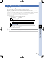
6. Troubleshooting
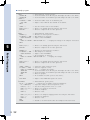
6.1.
Error messages
This section describes the error messages related to the external vision system.
Errors with error number [20.80] or later are those dedicated to the external vision system.
Errors with error numbers [20.00] to [20.79] are those common to the iVY system. For details, see the iVY
System User's Manual.
For details about errors other than those shown above, see relevant RCX240 Robot Controller User's Manual.
If an error occurs, relevant error message appears on the message line of the programming box.
For details about contents of each error message, see the list shown below.
[How to read the list]
The following shows the error message that appears on the screen.
Error group number
Error number
Error classification number
English error message
12.1 : EMG.STOP ON
Code: **** ---------------- Error code is expressed in the hexadecimal notation.
Meaning/Cause
************************************************************************
****
Corrective action
************************************************************************
****
6
Displays the actions to reset or avoid the error.
Displays the meaning and cause of the error.
Troubleshooting
n
NOTE
If the error cannot be solved even after taking the corrective action, contact your distributor.
33
20.80 : EX Vis calibration not set
Code
: &H1450
Meaning/Cause
Corrective action
The external vision calibration number you have specified is incorrect.
Change the external vision calibration number you want to specify.
Set the external vision calibration.
20.81 : EX_Vis EXCamera not set
Code
: &H1451
Meaning/Cause
Corrective action
The external vision parameter setting number you have specified is incorrect.
Change the external vision parameter setting number you want to specify.
Set the external vision parameters.
20.82 : EX Vis format error
Code
: &H1452
Meaning/Cause
Corrective action
The output format of the external vision is incorrect.
Check the output settings of the external vision.
20.83 : EX Vis response command miss match
Code
: &H1453
Meaning/Cause
6
Corrective action
The command is not sent to the external vision correctly.
Change the "response character string" of the external vision parameters.
Check the external vision state.
Check the connection settings between the robot controller and external vision.
Troubleshooting
20.84 : EX Vis work count error
Code
: &H1454
Meaning/Cause
Corrective action
The number of workpiece detections is beyond the detectable range.
Change the detection settings of the external vision.
Check the output format of the external vision.
20.85 : EX Vis work count miss match
Code
: &H1455
Meaning/Cause
Corrective action
The number of workpiece detections varies from the number of receive data (X,Y,θ).
Check the output format of the external vision.
20.86 : EX_Vis search timeout
Code
: &H1456
Meaning/Cause
Corrective action
The EXSEARCH command terminates due to timeout.
Change the timeout settings.
Check the external vision state.
20.87 : EX_Vis calib.data destroyed
Code
: &H1457
Meaning/Cause
Corrective action
34
An error occurs in the external vision calibration data.
Contact your distributor with details of the problem.
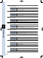
6.2
Actions to be taken if the communication fails.
If an error occurs during execution of the EXSEARCH command, check the communication settings or output
settings while referring to the flow shown below.
EXSEARCH
command execution
Error message
Conditions
Cause
Corrective action
Connections with the
external vision are not
established.
• Check the communication settings of the external vision and
controller.
• Check the communication port of the external vision parameters.
• Check the communication cable.
• Check the external vision state.
• Check the trigger input settings of the external vision.
Image capturing of
the external vision
is performed.
Timeout setting is too short.
• Change the search timeout setting of the external vision
parameters. It is necessary to make the timeout setting longer
than the time between image capturing of the external vision
and the result output.
Output settings are incorrect.
• Check the output settings of the external vision.
Image capturing of
the external vision
is not performed.
Image capturing of the
external vision is not
performed.
• Check the external vision state.
• Check the trigger character string of the external vision
parameters.
• Check the trigger input settings of the external vision.
Image capturing of
the external vision
is performed.
Response from the external
vision is not correct.
• Check the response character string of the external vision
parameters.
• Check the external vision state.
• Check the output settings of the external vision.
EX Vis work
count error
Number of workpiece
detections from the external
vision is beyond its range.
• Set the number of simultaneous workpiece detections of the
external vision to 0 to 40.
• Check the output settings of the external vision.
EX Vis work
count miss
match
Position data (X, Y, θ) for the
number of workpiece
detections is not acquired
from the external vision.
• Output the position data for the number of workpiece detections.
• Check the output settings of the external vision.
EX Vis format
error
Output from the external
vision is incorrect.
• Check the output settings of the external vision.
EX Vis response
command miss
match
63017-T7-00
35
6
Troubleshooting
Image capturing of
the external vision
is not performed.
EX_Vis search
timeout
7. Appendixes
7.1
Examples of controller and image sensor connections
This section describes examples of connections with the image sensors shown below.
• KEYENCE CV-X100 series
• OMRON FZ4 series, FQ-M series
• COGNEX EZ series, InSight series
KEYENCE CV-X100 series, OMRON FZ4 series, COGNEX EZ series, and InSight series are connected through
the RS-232C. OMRON FQ-M series are connected through the Ethernet.
For details about how to operate each image sensor, see relevant manual.
Note that the contents of this manual are those when the references were prepared and may slightly differ from
the actual displays and contents.
7.1.1 KEYENCE CV-X100 series
The following describes an example of connections with KEYENCE image sensor "CV-X100 series".
■ ■ Image sensors
Model
Description
CV-X150F
Multi-camera image sensor (Ver. 2.1)
CV-200M (2 units)
2-million-pixel black and white camera
■ ■ Communication settings
Match the communication settings of the image sensor to the RS-232C communication settings of the robot controller.
7
Communication settings of image sensor
Appendixes
64033-T7-00
36
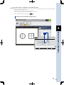
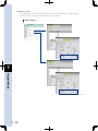
■ ■ Camera settings
When multiple cameras are installed, check on [Random Trigger] to trigger each camera.
Additionally, check on [RS-232C] in the "Trigger Mode" area.
Camera settings
64034-T7-00
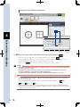
■ ■ Output settings
Set the output items of the image sensor so that they meet the output format stated in "2.3 Output settings".
The following shows an example of output settings when using two cameras.
7
Output settings
Appendixes
64035-T7-00
37
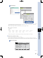
Check on [None] in the "Result Output at Skipped Tool" area and select "Comma" in the "Data Delimiter" field.
RS-232C (Non-Procedural) output settings
64036-T7-00
When the output settings shown above are made, the data is output as follows.
■ Image capturing of camera 1 Two workpieces are detected.
<< T1
>> T1
>> 0002,+00268.465,+00150.117,-00009.146,+00224.879,+00258.308,-00009.127
7
■ Image capturing of camera 2 One workpiece is detected.
<< T2
>> T2
Appendixes
>> 0001,+00308.401,+01150.829,-00010.002
■ ■ External vision parameter settings
Set the external vision parameters for the robot controller.
The image capturing command (trigger command) of KEYENCE CV-X series is "Tn (n shows the camera number.)".
Additionally, the response character string (response command) when the image sensor accepts the image capturing
command successfully is "Tn (n shows the camera number.)" that is the same as the image capturing command.
External vision 1 settings
SYSTEM>OPTION>EX CAM V10.72
EX Vision Camera PRM : EXCAM1 Trigger Command = T1
Response Command = T1
EX Cam FOV X [pix] = 1600
EX Cam FOV Y [pix] = 1200
TimeOut [100ms] = 30
Connection Port = CMU
64037-T7-00
38
External vision 2 settings
SYSTEM>OPTION>EX CAM V10.72
EX Vision Camera PRM : EXCAM2 Trigger Command = T2
Response Command = T2
EX Cam FOV X [pix] = 1600
EX Cam FOV Y [pix] = 1200
TimeOut [100ms] = 30
Connection Port = CMU
64038-T7-00
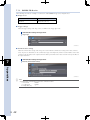
7.1.2 OMRON FZ4 series
The following describes an example of connections with OMRON image sensor "FZ4 series".
■ ■ Image sensors
Model
Description
FZ-4 xxx
Image sensor (Ver. 4.21)
FZ-SC
300-thousand-pixel color camera
■ ■ Communication settings
Match the communication settings of the image sensor to the RS-232C communication settings of the robot controller.
7
Communication settings of image sensor
Appendixes
64039-T7-00
39
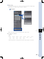
■ ■ Output settings
Set the output items of the image sensor so that they meet the output format stated in "2.3 Output settings".
The following shows an example of settings to detect up to six workpieces.
Output settings (1)
7
Appendixes
64040-T7-00
40
Output settings (2)
64041-T7-00
To detect multiple workpieces simultaneously, make the settings as shown above so that each data is separated by a
comma and a delimiter is put at the end of the data.
When the output settings are made as described above, the data is output as follows.
■ Two workpieces are detected.
<< MEASURE
7
>> OK
>> 2.0000,
452.5440,
212.2505,
176.0000,
441.1120,
0.0000,
0.0000,
0.0000,
0.0000,
0.0000,
0.0000,
0.0000,
0.0000,
0.0000,
0.0000
82.3567,
0.0000,
176.0000,
0.0000,
■ ■ External vision parameter settings
Set the external vision parameters for the robot controller.
The image capturing command (trigger command) of OMRON FZ4 series is "MEASURE". Additionally, the response
character string (response command) when the image sensor accepts the image capturing command successfully is "OK".
External vision settings
SYSTEM>OPTION>EX CAM V10.72
EX Vision Camera PRM : EXCAM1 Trigger Command = MEASURE
Response Command = OK
EX Cam FOV X [pix] = 640
EX Cam FOV Y [pix] = 480
TimeOut [100ms] = 30
Connection Port = CMU
64042-T7-00
41
Appendixes
* Character strings after the X, Y, and angle data for the number of detected workpiece are discarded.
7.1.3 OMRON FQ-M series
The following describes an example of connections with OMRON image sensor "FQ-M series".
■ ■ Image sensor
Model
FQ-MS120
Description
Image sensor (Ver. 1.4)
■ ■ Trigger settings
Check the trigger settings of the image sensor. Set "TRIG" in the "Trigger type" field.
Communication settings of image sensor
Trigger type
64043-T7-00
■ ■ Communication settings
Match the communication settings of the image sensor to the Ethernet communication settings of the robot controller.
Select "No protocol (TCP Client)" for the communication type on the FQ-M side, and then set the IP address of the robot
controller for the IP address at the output destination and the port number of the robot controller for the port number at
the output destination.
Communication settings of image sensor
7
Ethernet communication settings
Appendixes
64044-T7-00
n
42
NOTE
Set the Ethernet communication of the robot controller as follows.
6. Echo back
Invalid
8. Login check
Invalid
12. Keep alive [sec]
1
■ ■ Output settings
Set the output items of the image sensor so that they meet the output format stated in "2.3 Output settings".
The following shows an example of settings to detect up to six workpieces.
Output settings
64045-T7-00
7
When the output settings are made as described above, the data is output as follows.
Appendixes
■ Two workpieces are detected.
<< MEASURE
>> OK
>> 2.0000,
452.5440,
212.2505,
176.0000,
441.1120,
0.0000,
0.0000,
0.0000,
0.0000,
0.0000,
0.0000,
0.0000,
0.0000,
0.0000,
0.0000
82.3567,
0.0000,
176.0000,
0.0000,
* Character strings after the X, Y, and angle data for the number of detected workpieces are discarded.
43
■ ■ External vision parameter settings
Set the external vision parameters for the robot controller.
The image capturing command (trigger command) of OMRON FQ-M series is "MEASURE". The response character string
(response command) when the image sensor accepts the image capturing command successfully is "OK".
External vision settings
SYSTEM>OPTION>EX CAM V10.72
EX Vision Camera PRM : EXCAM1 Trigger Command = MEASURE
Response Command = OK
EX Cam FOV X [pix] = 752
EX Cam FOV Y [pix] = 480
TimeOut [100ms] = 30
Connection Port = ETH
64046-T7-00
7
Appendixes
44
7.1.4 COGNEX In-Sight EZ series
The following describes an example of connections with COGNEX image sensor "In-Sight EZ series".
■ ■ Image sensor
Model
In-Sight EZ-700
Description
Camera integrated image sensor
■ ■ Sample job loading
A sample job is available when using "In-Sight EZ-700". Connect the image sensor and communication software to load
this sample job.
* The sample job can detect up to six workpieces through one image capturing.
* For details about how to obtain the sample job, contact your distributor.
■ ■ Tool settings
Change the tool settings of the sample job corresponding to the workpiece. (See the figure below.)
1. From "2. Set Up Tools" in "Application Steps", select "Locate Part".
2. From "Results" in "Pallet", select "Patern_1".
3. Select the [Model] tab and set the workpiece to be detected.
Tool settings
2
7
1
Appendixes
3
64048-T7-00
■ ■ Output settings
The output settings are already made in the sample job. Change the settings when necessary.
45
■ ■ Communication settings
Match the RS-232C communication settings of the image sensor to the communication settings of the controller.
Communication settings of image sensor
64049-T7-00
Since the external image capturing command using character strings is not accepted when the communication settings
are set at "Serial Text", follow the steps below to make it possible to use "native command".
1 Check that the image sensor is in
the offline mode.
2 Connect to the image sensor
Step 2
through the Ethernet
communication.
Connecting to the image sensor
Run the terminal software ("Hyper Terminal",
etc. for Windows), and enter the IP address
of the image sensor and port number 23
(TELNET communication) to connect to the
image sensor.
7
64050-T7-00
3 Send the native command to the
image sensor.
Appendixes
After checking that the communication is
connected to the image sensor correctly,
send the native command shown below
through the Ethernet communication.
EV SetSerialPort(1,7,57600,8,1,512,0,0,0,13,13,
0,0,0)
64051-T7-00
When the image sensor accepts the native
command successfully, "1" is returned as return
value. Additionally, the image sensor is set as
follows and the native command becomes
valid in the RS-232C communication.
SerialPortNum:
Mode:
BaudRate:
DataBits:
StopBits:
Parity:
Handshake:
InputPacketSize:
OutputPacketSize:
InputTerminator:
OutputTerminator:
FixedInputMode:
FixedInputLength:
DeviceNetTrigger:
n
46
1
7 (Native mode)
57600
8
1
512 (Odd)
0 (None)
0
0
13(CR)
13(CR)
0
0
0
NOTE
Change values other than "Mode:7" when
necessary.
* The settings shown above are those when using Hyper Terminal.
Step 3
Sending the native command
n
NOTE
When the operation shown above is performed, the following message may appear. In this case, be sure to press
[No]. If you press [Yes] by mistake to restore the settings, perform steps 1 to 3 again.
4 Put the image sensor in the online mode.
5 Send the character string "SE8" to the image sensor through the RS-232C
communication.
Check that images are captured and the image capture results are output as follows.
* The number of workpiece detections is 6.
<< SE8
>> 1
>> 6,187.099,245.205,1.294,180.115,411.737,0.775,335.788,417.402,0.813,342.071,250.988,
1.037,491.151,422.774, 0.803,496.692,257.108,0.733
■ ■ External vision parameter settings
Set the external vision parameters for the robot controller.
The image capturing command of COGNEX EZ series is "SE8". The response character string when the image sensor
accepts the image capturing command successfully is "1".
External vision settings
7
SYSTEM>OPTION>EX CAM V10.72
64053-T7-00
47
Appendixes
EX Vision Camera PRM : EXCAM1 Trigger Command = SE8
Response Command = 1
EX Cam FOV X [pix] = 800
EX Cam FOV Y [pix] = 600
TimeOut [100ms] = 30
Connection Port = CMU
7.1.5 COGNEX In-Sight Micro series
The following describes an example of connections with COGNEX image sensor "In-Sight Micro series".
■ ■ Image sensors
Model
Description
In-Sight 1400
Camera integrated image sensor
CIO-MICRO-CC
Expansion I/O module
■ ■ Sample job loading
A sample job is available when using "In-Sight 1400". Connect the image sensor and communication software to load
this sample job.
* The sample job can detect up to ten workpieces through one image capturing.
* For details about how to obtain the sample job, contact your distributor.
■ ■ Tool settings
Change the tool settings of the sample job corresponding to the workpiece. From [Edit Region] of the sample job, register
the workpiece to be searched for.
Tool settings
7
Appendixes
64054-T7-00
■ ■ Output settings
The output settings are already made in the sample job. Change the settings when necessary.
* Output example: The number of detected workpieces is 10.
<< SE8
>> 1
>> 10,356.03,76.38,-49.154,289.03,153.88,40.809,57.93,429.67,40.060,132.85,339.65,40.179,40.42,362.34,
50.231,204.36,162.51,40.529,31.07,96.46,39.469,108.59,187.64,-49.841,369.07,59.61,41.111,283.781,
68.013,40.729
48
■ ■ Communication settings
Match the RS-232C communication settings of the image sensor to the communication settings of the controller.
Communication settings of image sensor
64055-T7-00
■ ■ External vision parameter settings
Set the external vision parameters for the robot controller.
The image capturing command of COGNEX EZ series is "SE8". The response character string when the image sensor
accepts the image capturing command successfully is "1".
External vision settings
SYSTEM>OPTION>EX CAM V10.72
EX Vision Camera PRM : EXCAM1 Trigger Command = SE8
Response Command = 1
EX Cam FOV X [pix] = 800
EX Cam FOV Y [pix] = 600
TimeOut [100ms] = 30
Connection Port = CMU
7
49
Appendixes
64056-T7-00
7.2
List of specifications
KEYENCE
CV-5000 series, CV-X100 series, XG series
OMRON
FZ4 series, FQ-M series
COGNEX
In-Sight EZ series, In-Sight series
Applicable model examples
Other general-purpose image sensor, PC etc.
Number of cameras
Max. 4 units *
Camera installation direction
Fixed camera (upward, downward), secured to the robot Y-axis.
Vertical to the image capturing target workpiece
Max. number of workpiece
detections
40 pcs. *
Communication type
RS-232C or Ethernet
Applicable commands
(Common to iVY system)
Commands dedicated to external
vision
VGETCNT, VGETPIX, VGETPOS
VGETPOSX, VGETPOSY
EXSEARCH
Image capturing command
Response character string
Parameters for external vision
(For 4 cameras)
Number of camera pixels
Timeout
Port to be used (CMU/ETH)
7
Calibration method
Interactive calibration method
Number of calibration data
Max. 4
Number of detected workpieces, X-coordinate, Y-coordinate, angle
Image sensor output settings
Each data is separated by a comma.
Appendixes
Delimiter is put at the end of the data.
* This value may vary depending on the image sensor to be used.
■ ■ Examples of camera installations
Camera is secured to the Y-axis.
Fixed camera (upward)
Fixed camera (downward)
63018-T7-00
50
7.3
Trademarks and registered trademarks
Cognex and In-Sight are registered trademarks of Cognex Corporation. ©2013Cognex Corporation
Windows is a registered trademark of Microsoft Corporation in the United States and other countries.
7
Appendixes
51
Revision record
Manual version Issue date
Ver. 1.01
Jun. 2014
Description
First edition
Robot vision system
RCX240 Connection Manual
Jun. 2014
Ver. 1.01
This manual is based on Ver. 1.01 of Japanese manual.
YAMAHA MOTOR CO., LTD. IM Operations
All rights reserved. No part of this publication may be reproduced in
any form without the permission of YAMAHA MOTOR CO., LTD.
Information furnished by YAMAHA in this manual is believed to be
reliable. However, no responsibility is assumed for possible
inaccuracies or omissions. If you find any part unclear in this manual,
please contact your distributor.
IM Operations
882 Soude, Nakaku, Hamamatsu, Shizuoka, 435-0054, Japan
Tel. 81-53-460-6103 Fax. 81-53-460-6811
Robot manuals can be downloaded from our company website.
Please use the following for more detailed information.
http://global.yamaha-motor.com/business/robot/
* For inquiries about the image sensor, please contact relevant manufacturer.
YAMAHA MOTOR CO., LTD.