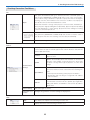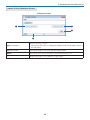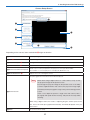
1
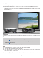
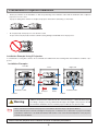
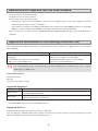
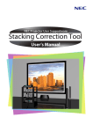
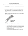
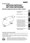
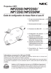
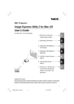
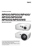
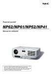
NEC Projector User Supportware
Stacking Correction Tool
User’s Manual
Introduction
Thank you for using the Stacking Correction Tool.
Please read this User's Manual carefully to aid in the proper use of this product before using the Stacking Correction Tool.
• The Stacking Correction Tool is software that uses the [GEOMETRIC CORRECTION] function of the NEC projector to easily
perform stacked projection.
Terminology
In this manual, the term stacking correction is used to describe the following processes performed by the Stacking Correction
Tool.
1. Photographing the projected images of multiple projectors with a digital camera or a web camera
2. Perform comparisons and calculations so that the content of the projected images is superimposed, and create the
GEOMETRIC CORRECTION data
3. Send the [GEOMETRIC CORRECTION] data to each projector
NOTE
(1)
Unauthorized reproduction of a part of or all of the content of this manual is prohibited.
(2)
The content of this manual is subject to change without notice.
(3)
Great care has been given to the creation of the content of this manual; however, should you notice any questionable
points, errors, or omissions, please contact us.
(4)
Notwithstanding section (3), NEC will not bear any responsibility for claims due to loss, lost profit, or other matters for
reason of the use of this software.
2
Precautions in Projector Installation
•
Please pay attention to the installation so that the positioning of the ventilation outlet and the ventilation inlet of adjacent
projectors is not too close.
A projector taking in the exhaust of an adjacent projector will result in overheating or other faults.
•
Do not physically stack projectors one above the other.
Projectors that are physically stacked could fall causing damage and breakdown of the projectors.
Installation Example Using 2 Projectors
In consideration of using this software, we recommend an installation like the following when the installation combines 2 projectors.
Installation Examples
Left side
Front
Ventilation outlet
Exhaust
Cabinet
Warning
Note
Right side
Ventilation inlet
Intake
Cabinet
Cabinet
• Please request ceiling mount and other special installation at your store of purchase. Installation should never be undertaken by the customer. Doing so could result in the projectors falling or in injury. A strong cabinet that will support the weight of the projectors should
be used in this installation. Do not stack the projectors directly one upon the other.
• Please see the user's manual of the projector for information about the range of projection distance.
• Leave sufficient space to the left and right of the projectors so that there is no obstruction of projector air intake
and exhaust. Obstruction of air intake and exhaust will result in a rise of the internal temperature of the projector
and will cause breakdown.
Please read the projector User's Manual for other installation precautions.
3
Restrictions on Projectors that Are to Be Installed
• Install all projectors on the same network.
• Set all projectors to the same resolution.
• Use the same model to the extent possible.
* When there is a difference in the brightness of the projectors, the digital camera or web camera might not accurately
read the projection image at the time of calibration.
* There will also be a difference in brightness depending on the setting of the [LAMP MODE]; therefore, set the [LAMP
MODE] to a uniform setting of either [NORMAL] or [ECO] for the projectors that are being installed.
• Please note that the use of this software for [DESKTOP REAR] and [CEILING REAR] projector projection methods is not
supported.
Application Environment of the Stacking Correction Tool
The following personal computer environment is recommended to provide convenient use of digital cameras or web cameras
when calibrating.
Windows Vista
Windows XP
Pentium 4, 2.4 GHz (A processor of 2.8 GHz or higher is rec- Pentium 4, 1.4 GHz, or AMD Athlon 1 GHz (A Pentium 4, 2.4
ommended)
GHZ processor or higher is recommended)
512 MB RAM (1 GB or greater is recommended)
128 MB RAM (256 MB or greater is recommended)
1 GB or more of free hard disk space
1 GB or more of free hard disk space
Note
Use of the Stacking Correction Tool should be performed by an "Administrator" for Windows Vista, and a "Computer
Administrator" for Windows XP.
Required Components
.NET Framework 3.5
DirectX 9
Java (Version 6, update 7 or later)
Supported Equipment
Projector
Digital camera
Web camera
NP3250/NP2250/NP1250/NP3250W*
Canon EOS Rebel XSi (in North America)
Canon EOS 450D (in Germany)
Logitech QuickCam® Pro 9000
Logitech QuickCam® Pro for Notebooks
* The number of pixels of the LCD panel of model NP3250W differs from that of the other 3 models; therefore, please use
model NP3250W projectors with others NP3250W projectors.
Supported Screens
Only flat screens are supported. Curved screens are not supported.
Note also that proper calibration might not be possible for rear projection screens and other screens in which there is a large
difference in brightness between the center and peripheral areas.
4
Steps up to Stacking Correction
Install the Stacking Correction Tool
Page 7
Install and connect the computer, projector, digital camera, or web camera
Install the Stacking Correction Tool
Page 14
Make adjustments to the projector, digital camera, or web camera
Projector preparation
Digital camera or web camera preparation
Perform the Stacking Correction
Page 18
Page 20
5
Page 19
Page 11
Table of Contents
Precautions in Projector Installation................................................................. 3
Restrictions on Projectors that Are to Be Installed.......................................... 3
Application Environment of the Stacking Correction Tool............................... 4
Steps up to Stacking Correction.......................................................................... 5
1. Installation of the Stacking Correction Tool.................................................. 7
Installing the Stacking Correction Tool....................................................................... 7
Uninstalling the Stacking Correction Tool.................................................................10
2. Installation and Connection of Equipment.................................................. 11
Connections for Stacking Correction........................................................................ 11
Connections for Projecting an Image................................................................. 12
3. Stacking Correction Tool Settings............................................................... 14
Starting the Stacking Correction Tool............................................................ 14
Names of the Stacking Correction Tool Screen............................................. 14
Stacking Correction Tool Menu..................................................................... 15
Names of the Calibration Screen................................................................... 16
4. Preparation of the Projectors...................................................................... 18
5. Preparation of the Digital Camera or Web Camera.................................... 19
6. Performing Stacking Correction.................................................................. 20
7. Calibration..................................................................................................... 23
8. List of Error Messages................................................................................. 25
6
1. Installation of the Stacking Correction Tool
Preparation:
Save the downloaded Stacking Correction Tool file to the desired location
* The same installation procedure is used for Windows Vista and Windows XP.
Installing the Stacking Correction Tool
1. Double click SCTxxx.exe
The installation screen will be displayed.
Note
Java (version 6, update 7 or later) and .NET Framework 3.5 are required in
the use of the Stacking Correction Tool. If these terms have not been satisfied, the screen to the right will be displayed when starting SCTxxx.exe.
When [Install] is selected, a connection will be made with the Internet and
downloading of the required component files from the distribution source
site will begin.
When the download is completed, the setup program will start automatically. Follow the instructions on the screen and complete the setup.
Java Installation Screen
* When making a new installation of .NET Framework 3.5 on Windows
XP (i.e., an older version of .NET Framework has not been installed),
the required component files will have a size of about 63 MB (and
about 20 MB when using Windows Vista). It could take a considerable
time from the start of downloading to the completion of installation.
Also, if requested to restart Windows after installing .NET Framework
3.5, please follow the instructions and restart Windows. The installation of the Stacking Correction Tool will continue after restarting Windows.
.NET Framework 3.5 Installation Screen
* If connection cannot be made with the Internet, use another computer
that can connect with the Internet and access the URL listed below,
then download the required component files and use them.
[Java]
http://www.java.com/en/
[.NET Framework 3.5]
http://msdn.microsoft.com/en-us/netframework/default.aspx
7
1. Installation of the Stacking Correction Tool
2. Select "I accept the terms in the license agreement" and click [Next].
Please read the content of the END USER LICENSE
AGREEMENT carefully.
A screen for verifying the installation location will be displayed.
3. Click [Next]
To change the installation location, click [Change] and specify
the installation location.
A screen notifying that the installation preparation has been
completed will be displayed.
4. Click [Install]
The installation will begin.
As the installation proceeds, installation will start for applications required in the operation of the Stacking Correction Tool.
5. Click [OK]
A screen for verifying the installation location will be displayed.
Note
If a language selection screen is displayed, select the language and click [OK].
8
1. Installation of the Stacking Correction Tool
6. Click [Install]
The installation will start.
To change the installation location, click [Browse…] and specify
the installation location.
Note
DirectX 9 or later is required in the use of this application.
If these terms have not been satisfied, the screen to the right will
be displayed.
Follow the instructions on the screen and complete the setup of
DirectX Installation Screen
DirectX 9.
7. Click [Close]
This completes the installation of the Stacking Correction Tool.
Click [Finish] on the screen and close the setup program.
9
1. Installation of the Stacking Correction Tool
Uninstallation of the Stacking Correction Tool
Windows Vista
Select the Stacking Correction Tool from [Uninstall a program] under [Control Panel] and uninstall it.
Windows XP
Select the Stacking Correction Tool from [Add/Remove Programs] under [Control Panel] and uninstall it.
10
2. Installation and Connection of Equipment
Connections for Stacking Correction
LAN
Projector
Digital camera
Web camera
WIRELESS
WIRELESS
WIRELESS
COMPUTER1 IN
Projector
LAN
COMPUTER1 IN
WIRELESS
LAN
or
To digital
connector
To USB port
Note
To LAN port
Computer (for stacking correction)
• Install the digital camera or web camera facing the projection image.
• The photographic coverage of the digital camera or web camera is 30˚.
• Plug each projector into a power outlet.
• Connect each of the projectors to the same network.
• Use LAN cable that supports Category 5 or higher for the connection to the network.
11
Projector
2. Installation and Connection of Equipment
Connections for Projecting an Image
RGB Signal
COMPUTER1 IN
COMPUTER1 IN
WIRELESS
WIRELESS
WIRELESS
WIRELESS
WIRELESS
WIRELESS
COMPUTER1 IN
Projector
Projector
Projector
VGA signal cable
VGA signal cable
1
2
3
Analog RGB output
Analog RGB input
Analog RGB signal divider
(Mini D-Sub 15 pin)
Computer
To displayed output
connector (Mini D-Sub 15 pin)
VGA signal cable
Note
• When the projectors are connected with a daisy chain connection, the RGB video signal will be attenuated
and its projection might not be possible. Use an RGB signal divider as illustrated in the above connection
diagram.
Daisy Chain Connection
COMPUTER1 IN
MONITOR OUT
COMPUTER1 IN
MONITOR OUT
To Computer 1 input
of the next projector
RGB output
connector of PC
Reference
• Connections can also be made using commercially available BNC cable.
12
2. Installation and Connection of Equipment
Make connections as illustrated in the diagrams below when connecting video equipment other than the computer (e.g., DVD
players, S-video, etc.).
Component Signal
COMPONENT IN
COMPONENT IN
Projector
COMPONENT IN
Projector
Projector
Component video cable
Component video cable
Y
DVD component
signal divider
Cb Cr
Output1
Y
Cb Cr
Output2
Y
Cb Cr
Output3
Input
Y
Cb Cr
Component video cable
L
Y
R
Cb
Cr
Audio output Component output
DVD player
S-video signal
S-VIDEO IN
S-VIDEO IN
Projector
S-VIDEO IN
Projector
Projector
S-video cable
S-video cable
S-video cable
1
S-video signal
divider
2
3
S-video output
S-video input
S-video cable
L
R
Audio output
VIDEO
S-VIDEO
Video output
DVD player / Video deck
Reference
• Connections can also be made via network using Image Express Utility 2.0.
13
3. Stacking Correction Tool Settings
Starting the Stacking Correction Tool
The same Stacking Correction Tool starting method is used for Windows Vista and Windows XP.
Select the Stacking Correction Tool from [Start] → [All Programs] → [NEC Projector User Supportware] and start it.
Names of the Stacking Correction Tool Screen
Stacking Correction Tool Main Screen
❶
❷
❸
❹
❺
❶ List of Connected Projectors
Displays the connection order, IP address, projector name, and resolution for the currently
connected projectors.
❷ Destination of Geometric Cor- Select settings 1 to 3 of the projector's [GEOMETRIC CORRECTION] onscreen menu
as the [GEOMETRIC CORRECTION] data storage location after stacking correction.
rection Data
❸ Calibration Mode
Master Projector:
The projector that will serve as the master is determined, and the projection image of
another projector undergoes stacking correction so that it is in agreement with the projection image of the master projector.
In this instance, the [GEOMETRIC CORRECTION] of the master projector does not
change.
Auto:
When there is a screen frame, the projection image is corrected so as to fit inside that
frame.
When there is no frame, correction is applied so that the area of the rectangle is maximized within the superimposed portion of the projection area.
The aspect ratio of the input signal is not maintained at this time.
❹ [Next]
Display the calibration screen. (
❺ [Exit]
Closes the Stacking Correction Tool.
14
Page 16)
3. Stacking Correction Tool Settings
Stacking Correction Tool Menu
File
Open
This opens the GCXS file (with .gcxs extension) that was saved with [Save as]
and sends the [GEOMETRIC CORRECTION] data to each of the connected projectors. When using a GCXS file to reproduce a projection that has undergone
stacking correction, the installation and connection condition of each projector
must be the same as when the GCXS file was saved.
When there has been a change of the projector connection order, installation position, projection angle (including tilt foot adjustment), projection position (including
lens shift adjustment), or other settings, projection that has undergone stacking
correction cannot be reproduced.
Save as
*can be selected
w h e n stac k in g
correction is
completed
This gathers the [GEOMETRIC CORRECTION] data, and the connection order of
each projector and saves it as stacking correction data (in a GCXS file).
Exit
Closes the Stacking Correction Tool.
Options
The projectors that will be used in stacking correction are selected with this
screen. Select the type of network (type of NIC: network interface card) with the
topmost pull-down menu.
Connect
Detects a projector that is connected to the network and displays it on a list.
Update
Updates the list display when there has been an increase or
decrease of the number of network projectors, when there
has been a change in the type of projector, or some other
change.
Input Address
Specifies and searches the IP address of the projector.
The search method can be selected from the following two
types.
• Direct input and searching of the projector IP address
• Specification and searching of a range with start address
and end address
Edit List
Specifies an address and registers on a list the projectors
that have been searched. This also permits post registration
editing and deletion, and additions and searches by address
specification.
Communication
Settings
Camera Setting
Selects the type of camera.
Geometric Correction
Changes the geometric correction settings of the projector.
Help
This displays the help file of the Stacking Correction Tool.
About
Displays the version of the Stacking Correction Tool.
Help
15
3. Stacking Correction Tool Settings
Names of the Calibration Screen
Calibration Screen
❶
❷
❸
❹
Starts the stacking correction
❶ Start Calibration
* When using a web camera, clicking [Start Calibration] will start the utility software of
the web camera.
❷ Camera Setup
Performs the angle of view check and other camera checks.
❸ Quit
Discontinues the correction and returns to the Stacking Correction Tool.
❹ Calibration Progress
Displays the progress of the calibration as a percentage.
16
3. Stacking Correction Tool Settings
Camera Setup Screen
❺
❶
❷
❼
❸
❹
❻
❽
Depending on the camera, items marked with C might not function.
❶ Take Another Picture
Takes a photograph.
❷ Gain C
Adjusts the gain of the digital camera.
❸ Curent ISO Speed C
Changes the ISO speed of the digital camera.
❹ Curent Resolution C
Adjusts the resolution of the digital camera.
❺ Show Focus Pattern on Projector
❻ Zoom Out/Zoom In C
Sends a (15 x 15 dot) test pattern to the projector of the specified number.
The number of connected projectors is displayed. (Maximum of 4.)
Adjusts the zoom of the digital camera.
The photographs that have been taken will be displayed.
Note
Either when using a digital camera or a web camera, set up so that
the projection image fits this preview screen.
Even though the projection image fits the preview screen of the utility
software supplied with the web camera, the projection image might
extend beyond the photographic range in the [Camera Setup] preview
❼ Preview Screen
screen.
If this occurs, adjust the position or angle of the web camera, take a
photograph with [Take Another Picture], and perform the setup while
checking.
When using a digital camera, the results of adjusting the gain, shutter speed, resolution, and zoom will be photographed automatically, and will be displayed on the preview screen.
❽ Finish
Closes the Camera Setup.
17
4. Preparation of the Projectors
The projectors used in the stacking correction will now be prepared. Please refer to the user's manual of the projector in conjunction with the description given in this manual.
1. Install and connect the projectors that will be used,
and project them onto the screen (The portion of
projectors that will be used)
Connection of the Equipment
Page 11
2. Adjust the Projectors
Refer to the projector user's manual and perform the following adjustments.
• Adjust so that the projection image of each projector enters the
screen.
• Set [LAMP MODE] to the same setting for each of the projectors.
• Make image quality adjustments, projection position adjustments, and zoom and focus adjustments as required.
• When performing the stacking correction in conjunction with the projection screen of the master projector,
perform the [CORNERSTONE] adjustment for the projector that will be the master. If the projection image of
the master projector is distorted, stacking correction will be also performed for the other projectors in conjunction with the distorted projection image.
* When there has been a selection of [By detecting the most extreme corners] (i.e., stacking correction at the
maximum allowable size), the [CORNERSTONE] setting of all of the projectors will be reset and there will be
no need to make the setting.
Note
• The [CORNERSTONE] screen will not be displayed when making adjustments with the [KEYSTONE] screen, or
when setting [GEOMETRIC CORRECTION]. To perform the [CORNERSTONE] adjustment, hold down the 3D REFORM button for 2 seconds or longer, and clear the [KEYSTONE] adjustment values.
Likewise, the [KEYSTONE] screen will not be displayed when making adjustments with the [CORNERSTONE]
screen, or when setting [GEOMETRIC CORRECTION]. To perform the [KEYSTONE] adjustment, hold down the
3D REFORM button for 2 seconds or longer, and clear the [CORNERSTONE] adjustment values.
Reference
• When making settings on a number of projectors, it will be convenient to use the optional remote control (NP02RC). Using the projector [CONTROL ID] function, one optional remote control will permit the operation of individual projectors,
or the operation of all projectors at once. Please see the projector user's manual for information about the [CONTROL
ID] setting.
• Setting a [PROJECTOR NAME] to a projector in advance will aid in recognition even in the list displayed in the Stacking
Correction Tool [Communication Settings], and will be convenient at the time of installation.
Please see the projector user's manual for information about the [PROJECTOR NAME] setting.
18
5. Preparation of the Digital Camera or Web Camera
The digital camera or web camera used in the stacking correction will now be prepared. Please refer to the user's manual of
the digital camera or web camera in conjunction with the description given in this manual.
1. Perform Settings of the Digital Camera or Web Camera that Will Be Used
Optimal camera settings will be made for the stacking correction.
Set the digital camera or web camera as described below.
Digital Camera
Setting Item
Selection
Notes
Select M (Manual exposure) from among the five applicable
Mode dial on the digital camera body
M
exposure modes of A-DEP (automatic depth of field priority
AE), M (manual exposure), Av (aperture priority AE), Tv (shutter priority AE), and P (program AE).
Focus mode switch on the digital
MF
camera body
Stabilizer switch on the digital cam-
OFF
era body
Select MF (manual focus) from among the two modes of AF
(automatic focus) and MF (manual focus).
Set the stabilizer switch to OFF.
Web Camera
Install the utility software that comes with the web camera and after startup, perform the settings as described
below.
Setting Item
Webcam
Focus
Settings
White Balance
Selection
[Manual Focus]
Manual
Use Automatic RightLight™ Settings
Exposure/Gain
Advanced
Settings
adjustment
Off
Manual
Anti Flicker
[Off]
LED Control
[Off]
Notes
Change to [Manual Focus] when [Auto Focus] is selected.
Uncheck the "Auto" check mark.
Uncheck the "Use Automatic RightLight™ Settings" check
mark.
Uncheck the "Use Automatic Settings" check mark.
Select Off from among Off, 50 Hz (Europe), and 60 Hz (North
America).
Select [Off] from among [Off], [On], and [Automatic].
2. Make a Connection to the Computer
Using the USB Cable
Connection of the Equipment
Page 11
* Use the USB connection cable that comes
with the digital camera or the web camera.
To the USB port of the computer
19
6. Performing Stacking Correction
The stacking correction will be performed after completion of the connections of the projectors, digital camera or web camera,
and the computer.
1. Start the Stacking Correction Tool
2. Select the Projectors
Select [Communication Settings] of the [Options]
menu, then ❶ select the network type, ❷ enter
a check mark for the projectors that will be used,
click [Connect], and add to the list.
* Up to a maximum of 4 projectors can be used in
stacking correction.
❶
❷
3. Select the Camera
Select the camera type with [Camera Setting] under [Options].
4. Select the [GEOMETRIC CORRECTION]
data storage location
The default setting is [1].
Note
In the projector, GEOMETRIC CORRECTION
data has already been registered in 1 to 3 as the
default setting.
The existing GEOMETRIC CORRECTION data
of the selected number will be overwritten in the
saving location by the Stacking Correction Tool.
20
6. Performing Stacking Correction
5. Select the Type of Stacking Correction
* When the master projector has been determined and
stacking correction is going to be performed, this setting selects which projector in the group will be made
the master.
6. Click [Next]
The calibration screen will be displayed.
Click [Camera Setup] and perform the camera adjustments. (
Page 17, 24)
When the web camera is connected, perform the required
settings with the utility software that came with the web
camera. (
Page 24)
7. Click [Start Calibration]
Calibration will start.
Four types of test image (illustrated below) will be projected onto the screen in order.
Note
During the calibration, please pay attention to the following points:
• Do not touch the installation platform of the camera or projector.
• Do not cut across in front of the camera.
• Do not let shadows from outside light fall upon the screen.
First: Completely black image
Second: Completely white image
Third: Image of dots (Five dots at screen center)
Fourth: Image of dots (Screen full of dots)
21
6. Performing Stacking Correction
Test images for the number of projectors connected will be sent and projected.
* Screens on which test images are projected will be photographed by digital camera or web camera, and will
be used as data for the calculation of stacking correction.
When an error message is displayed at the time of sending the test image, and calibration cannot be completed, please see "Calibration" (
Page 23), and "Error Message List" (
Page 25).
There will be a return to the Stacking Correction Tool screen upon completion of the calibration.
8. Click [OK]
This completes the stacking correction.
Note
• When GEOMETRIC CORRECTION is set, KEYSTONE and CORNERSTONE cannot be selected.
• Hold down the 3D REFORM button for 2 seconds or longer to clear the GEOMETRIC CORRECTION data that
has been set.
• GEOMETRIC CORRECTION performs an electrical correction and as such there may be a resultant drop in
brightness or deterioration of picture quality.
• Exceeding the limits of the correction or other factors may result in distortion of the picture or correction not being applied at all.
Reference
• After correction, fine adjustment is permitted with lens shift or lens zoom focusing.
• Changes of conditions following installation and other factors may result in a shift of the image on the screen. Regular use of stacking correction will maintain the accuracy.
22
7. Calibration
In calibration, differences in brightness on the screen are identified and calculations are performed.
Also, for the purpose of the calculations, the contour of the projection image, and the position and shape of the test image are
photographed with a digital camera or a web camera.
If an error message is displayed during the calibration, first check the items listed below.
Item to Check
Has the resolution of each of the projectors
been adjusted?
Cause and Action to Take
The number of pixels of the LCD panel of the model NP3250W differs from
other projectors; therefore, the NP3250W cannot be used at the same time as
models NP3250, NP2250, and NP1250.
To the extent possible, use the same model of projector in the stacking correction. When there is a difference in brightness between projectors, recognition of the contour or the position and form of the test image may not be pos-
Has the brightness of each of the projec-
sible with one of the projection images.
tors been adjusted?
Note also that a difference in brightness may arise from a difference of the
setting of the projector LAMP MODE; therefore, each projector should be set
to the same setting. See the projector user's manual for information about the
LAMP MODE setting.
Please use a model that is supported by the Stacking Correction Tool as list-
Is the digital camera or web camera com-
ed on Page 4. Note also that even though a supported model is used, please
patible with the Stacking Correction Tool?
check whether the model is properly selected with [Camera Setting] under
[Options]. (
Is the digital camera or web camera set as
specified by the Stacking Correction Tool?
Page 15, 20)
When the automatic adjustment function of the digital camera or web camera
is enabled, an error may occur during calibration. Please set the digital camera or web camera as described on Page 19.
Make adjustments so that the overall projection image can be photographed
as large as possible; for example, move the setup position of the digital camera or web camera, or use the zoom function.
* When using the web camera, even when the entire projection image is gathered within the photographic range in the supplied utility software preview
screen, the projection image might be shifted outside of the photographic
range in the [Camera Setup] preview screen. If this happens, it will not be
possible to complete stacking correction (and a message will be displayed to
move the camera).
Is the entire screen gathered within the
Preview Screen of the Web
Camera Utility Software
photographic range of the digital camera
or web camera?
Yes
No
23
[Camera Setup] Preview
Screen
7. Calibration
After checking the items of the previous page, if an error still occurs during calibration, it is possible that the quality of the image photographed by the digital camera or web camera is insufficient and cannot be recognized.
Please pay attention to the points described below and make adjustments of the photographic image using the camera setup
screen or the utility of the web camera, then try the calibration.
• Set a higher resolution of the camera.
• Perform the gain adjustment while observing the preview screen.
• Set up and adjust the camera so that the background of the screen (e.g., walls, etc.) does not enter the photographic range of
the camera.
When there is a difference in brightness between the screen and the background, an error may occur during calibration.
Camera Adjustment Examples
[Camera Preview Screen]
Aim at the right image and adjust the camera so that the difference in brightness
between the test image and the screen becomes distinct.
Completion of calibration may not be possible in situations such as the following.
Photographic Screen is too Bright
Adjust the gain and the exposure.
Note
Extraneous Light Enters the Photo-
The Contour of the Projected Image Falls Out-
graphic Range
side of the Photographic Range
Use the camera zoom function, or
Adjust the installation position of the
adjust the installation position so that
camera so that the contour of the pro-
extraneous light does not enter the
jection image fits into the photographic
photographic range.
range.
When making adjustments with the web camera utility software, perform the adjustments after exiting the Calibration Screen and the Camera Setup screen to permit the post-adjustment values to be reflected. Making adjustments while the Calibration Screen or Camera Setup screen is displayed will result in the values returning to what
they were at the time of beginning the correction.
24
8. List of Error Messages
When an error occurs during the calibration and a message is displayed, please refer to the table below and respond as indicated.
Reference
• Error messages extract a portion of the display content.
• Rarely, an error message that is not listed in this manual may be displayed.
If this happens, check the photographic image of the camera or the adjustment and position of the camera according
to the error message.
Error Message
Cause of Error
Response to Error
The projection image does not fall
within the photographic range of
the camera.
• Make adjustments so that the overall projection image can
be photographed as large as possible; for example, move
the setup position of the digital camera or web camera, or
use the zoom function.
The brightness at the periphery is
low, and the test pattern cannot be
detected.
• Check the photographic image of the camera, adjust the
gain and other settings, and check the difference in brightness between the test pattern and the background. Also,
darken the peripheral illumination as much as possible.
Unable to find a usable camera.
and
No Camera Found.
The camera that was specified
with the camera settings cannot
be found.
• Check that the model has been correctly selected with
[Camera Setting] under [Options].
Could not initialize the Canon camera.
The camera that was specified
with the camera settings cannot
be found.
• Check the connections of the camera power supply and
USB cable.
• Check that the model has been correctly selected with
[Camera Setting] under [Options].
Camera Initialization Error
Camera initialization error
• When calibration is performed with the preview screen
started on the utility software of the web camera, the projection image of the test pattern cannot be photographed
with [Calibration Screen] of the Stacking Correction Tool.
Close the preview screen of the utility software and perform the calibration again.
Too many spots found.
and
Too few spots found.
The correction points cannot be
properly detected from the test
pattern.
• Check the photographic image of the camera, adjust the
gain and other settings, and check the difference in brightness between the test pattern and the background. Also,
darken the peripheral illumination as much as possible.
The programmer called a function
that is not implemented.
A function not supported by the
camera was used.
• Press the [Dismiss] button and return to the original
screen.
Maximum value reached, cannot increase more
and
Minimum value reached, cannot decrease more
The maximum value or the
minimum value of the adjustment
range has been reached.
• Press the [Dismiss] button and return to the original
screen.
The region found seems to use a very
small using roughly xx by yy pixels in
the camera.
A n a p p r o p r i ate p h o t o g r a p h i c
range cannot be detected.
• Check whether the screen has become too bright from outside light striking it.
• Check the photographic image of the camera, adjust the
gain and other settings, and check the difference in brightness between the test pattern and the background. Also,
darken the peripheral illumination as much as possible.
Found Maximum Colors of (rrr, ggg,
bbb) with a highest possible value of
255.
There is insufficient brightness
and the test pattern cannot be detected.
• Check the photographic image of the camera, adjust the
gain and other settings, and check the difference in brightness between the test pattern and the background. Also,
darken the peripheral illumination as much as possible.
Error Writing Image NEC Projector:
(IP address)
There is an error in communication with the projector.
• Check the condition and connections of the projector, and
perform the calibration again.
Unable to find a grid from the spots.
The correction points cannot be
properly detected from the test
pattern.
• Check the photographic image of the camera, and adjust
the camera or move the camera position so that the entire
test pattern can be read. Also, darken the peripheral illumination as much as possible.
Please move the camera. The projector is not entirely in view.
25
Trademarks
• Microsoft, Windows, Windows Vista, .NET Framework, and DirectX are either registered trademarks or trademarks of Microsoft Corporation in the United States and other countries.
• Java is a registered trademark of Sun Microsystems, Inc. in the United States and other countries.
• Powered by Scalable Display Technologies
Protected by US Patent 6,456,339 and patents pending
• Canon and EOS are registered trademarks of Canon Inc.
• Logitech and QuickCam® are trademarks or registered trademarks of Logitech Inc.
© NEC Display Solutions, Ltd. 2009
Ver. 1 06/09
26