1
Instruction
Manual
Model TB450G-H
NTU-compliant Surface Scattered Type
Turbidity Meter [High Range Type]
IM 12E04A03-02E
IM 12E04A03-02E
1st Edition
Introduction
This instruction manual describes on the specifications, principle of measurement,
and maintenance for Model TB450G-H High-range type NTU-compliant Surface
Scattered Type Turbidity Meter.
For the Model TB450G-H high-range type, refer to other instruction manual "IM
12E04A03-01E".
Notation
Symbol Marks
In this manual, the following symbols are used to represent the following contents.
Warning ............... Description of precautions to take against dangers such as electric
shock that can cause fatal or serious injury to the operator.
Important ............ Description of precautions to take against damaging software or
hardware that could cause a failure in the system.
Note ...................... Description of items to be noted in order to understand the
operation and features of the equipment.
Tip .......................... Additional information.
Reference ........... An item or a page to be referred to.
IM 12E04A03-02E
1ST Edition: Apr 2000 (YK)
All Rights Reserved, Copyright © 2000, Yokogawa Electric Corporation
IM 12E04A03-023E
i
NOTATION
Notice about this manual book
• Pass this book to the final user.
• Read this book thoroughly to understand the contents before operating the equipment.
• This book is to describe the functions of the product in detail, and not to warrant that
the product match to each customer’s requirement.
• Do not reprint or duplicate any part or all of this book without YOKOGAWA’s
permission.
• The content of this book may be altered without notification.
• We made our best effort to complete this book, however, if you find any questionable
matters, error, or insufficient description, please contact our agent nearby, or our sales
division.
Notice about protection, safety, and changing of our product
• For protection and safety of the product and the system controled with the product,
operate the product in compliance with the safety instructions in this book.
• Any protection or safety circuit adapted to the product or the system controled with the
product must be installed separately outside of our product. Do not make any modification of the product to install them inside the product.
Exemption from responsibility with the product
• We do not warrant our product except as provided in the warranty clauses.
• We do not have any responsibility for direct or indirect damages of the customer or
any third party caused by using our product or unexpected fault of our product
ii
IM 12E04A03-02E
Contents
Introduction ........................................................................................................................... i
Notation
........................................................................................................................... i
NOTATION ..................................................................................................................
Notice about this manual book .....................................................................................
Notice about protection, safety, and changing of our product .....................................
Exemption from responsibility with the product ..........................................................
1.
ii
ii
ii
ii
OVERVIEW ................................................................................................ 1-1
1.1
System Configuration ...................................................................................... 1-2
1.1.1 Configuration with Only TB450G Converter and Detector ................... 1-2
1.1.2 Configuration with Sampling System ..................................................... 1-2
1.1.3 Configuration with Sampling System and Automatic Cleaning System 1-3
1.1.4 Configuration with Sampling System, Automatic Cleaning System, and
Automatic Zero Calibration System ....................................................... 1-3
1.2
Operating Principle ......................................................................................... 1-4
1.3
Turbidity Standard .......................................................................................... 1-6
1.3.1 Standard Water for Zero Calibration ...................................................... 1-6
1.3.2 Standard Water for Span Calibration ...................................................... 1-6
2.
SPECIFICATIONS ..................................................................................... 2-1
2.1
2.2
2.3
2.4
2.5
2.6
2.7
Standard Specifications ................................................................................... 2-1
Characteristics ................................................................................................. 2-6
Model and Suffix Codes ................................................................................. 2-6
Accessories ...................................................................................................... 2-6
Spare Parts ....................................................................................................... 2-7
Sampling Parts ................................................................................................ 2-7
External Dimensions ....................................................................................... 2-8
2.7.1 TB450G-#-#-#-NN-NN ........................................................................... 2-8
2.7.2 1 micron filter with case (Part No. K9411UA) ...................................... 2-9
2.7.3 Head Tank (With Manual operated Valve) ; K9411GC; ....................... 2-9
2.7.4 Head Tank (With Pinch Valve) K9411JA, K9411JB .......................... 2-10
2.7.5 Mounting Bracket for Head Tank; Part No. K9411BB ........................ 2-10
2.8
Example Piping Diagram Recommended systems shown below ................ 2-11
2.8.1 Without Automatic Cleaning and Automatic Zero Calibration............ 2-11
2.8.2 With Automatic Cleaning without Automatic Zero Calibration .......... 2-11
2.8.3 With Aotomatic Cleaning and Automatic Zero Calibration ................. 2-12
2.9
Internal Wiring Diagram ............................................................................... 2-13
3.
INSTALLATION. PIPING. AND WIRING ............................................ 3-1
3.1
Installation .......................................................................................................
3.1.1 Unpacking ................................................................................................
3.1.2 Installation Location ................................................................................
3.1.3 Installation ...............................................................................................
3.2
Piping ...............................................................................................................
3.2.1 When Using TB450G Converter and Detector Alone ............................
3.2.2 When Using TB450G with Sampling System ........................................
IM 12E04A03-023E
3-1
3-1
3-1
3-1
3-4
3-4
3-6
iii
3.3
4.
Wiring .............................................................................................................. 3-8
3.3.1 Wiring between Converter and Detector ................................................ 3-9
3.3.2 Wiring between Converter and Valves SV1/2 – when Using Automatic
Cleaning Function ................................................................................... 3-9
3.3.3 Wiring between Converter and Valves SV1/2/3/4 – when Using Automatic
Cleaning Function and ..................................................................................
Automatic Zero Calibration Function ................................................... 3-10
3.3.4 Power and Grounding Wiring ............................................................... 3-10
3.3.5 Analog Output Wiring ........................................................................... 3-11
3.3.6 Digital Output Wiring ........................................................................... 3-11
3.3.7 Contact Input (Remote Range Swtiching) and Contact Output (Range
Output) Wiring (If necessary) ............................................................... 3-12
3.3.8 Contact Output (During maintenance, failure, upper or lower limit alarm,
during automatic cleaning, during automatic zero calibration) Wiring (If
necessary) .............................................................................................. 3-13
OPERATION ............................................................................................... 4-1
4.1
Preparation for Operation ............................................................................... 4-1
4.1.1 Checking Piping and Wiring Conditions ................................................ 4-1
4.1.2 Supplying Power ..................................................................................... 4-1
4.1.3 Setting Sampling Specification ............................................................... 4-1
4.1.4 Feeding Zero Calibration Water .............................................................. 4-2
4.1.5 Adjusting Flow Rate of Feed to Detector ............................................... 4-4
4.1.6 Feeding Cleaning Water .......................................................................... 4-5
4.1.7 Setting Output Range .............................................................................. 4-5
4.1.8 Running-in ............................................................................................... 4-5
4.1.9 Zero and Span Calibrations ..................................................................... 4-5
4.1.10 Feeding Measured Water and Adjusting Measured Water Flow Rate ... 4-6
4.2 Operation ......................................................................................................... 4-7
4.2.1 Starting Measurement .............................................................................. 4-7
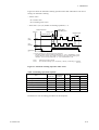
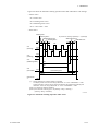
4.2.2 Automatic Cleaning Operation ................................................................ 4-8
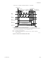
4.2.3 Automatic Zero-calibration Operation .................................................. 4-12
5.
FUNCTIONS................................................................................................ 5-1
5.1
5.2
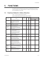
Functions Related to Failure Detection .......................................................... 5-1
Functions Related to Analog Output .............................................................. 5-4
5.2.1 Output Range Selection ........................................................................... 5-4
5.2.2 Other Functions Related to Output ......................................................... 5-6
5.3 Manual Cleaning and Calibration Functions .................................................. 5-8
5.4 Functions Related to Display ........................................................................ 5-10
5.5 Functions Related to Contact Output ............................................................ 5-11
5.6 Other Functions ............................................................................................. 5-11
5.6.1 Overview of the Option “ Bubble Retardant ” ..................................... 5-11
5.6.2 Settings for Executing the “ Bubble Retardant ” Option ..................... 5-13
6.
PROCEDURES FOR CONVERTER OPERATION .............................. 6-1
6.1
6.2
iv
Components of Operation Panel and Their Functions and Actions ............... 6-1
Operation Modes and Functions ..................................................................... 6-3
6.2.1 Functions in < MEAS. > Mode ............................................................... 6-4
6.2.2 Functions in < MAINT. > Mode ............................................................. 6-5
6.2.3 Functions in < PROGRAM1 > Mode ..................................................... 6-6
6.2.4 Functions in < PROGRAM2 > Mode ..................................................... 6-7
IM 12E04A03-02E
6.3
Key Operation ................................................................................................. 6-8
6.3.1 Mode Switching ....................................................................................... 6-8
6.3.2 Function Switching .................................................................................. 6-8
6.3.3 Numerical Input ....................................................................................... 6-9
6.3.4 Opening / Closing Valves ....................................................................... 6-9
6.4
Operation in < MEAS. > Mode .................................................................... 6-10
6.5
Operation in < MAINT. > Mode .................................................................. 6-12
6.6
Operation in < PROGRAM1 > Mode .......................................................... 6-23
6.7
Operation in < PROGRAM2 > Mode .......................................................... 6-46
6.8
Valve Operation ............................................................................................ 6-49
7.
MAINTENANCE ........................................................................................ 7-1
7.1
7.2
7.3
7.4
7.5
7.6
Items of Inspection and Maintenance and Their Periods ............................... 7-1
Washing With Cleaning Water ....................................................................... 7-2
Cleaning of Measuring Cell ............................................................................ 7-3
Cleaning of Deforming Tank .......................................................................... 7-4
Lamp Replacement .......................................................................................... 7-5
Zero Calibration .............................................................................................. 7-7
7.6.1 Zero Calibration with “ Zero Water ” ..................................................... 7-7
7.6.2 Zero Calibration by Turning Off Light Source ...................................... 7-8
7.7
Span Calibration .............................................................................................. 7-9
7.7.1 Span Calibration Using Calibration Plate ............................................... 7-9
7.7.2 Span Calibration Using Standard Solution ........................................... 7-11
7.8
Cleaning of Lenses ........................................................................................ 7-12
7.9
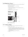
Replacement of Filter (for “ zero water ”) ................................................... 7-13
7.10 Replacement of Fuses ................................................................................... 7-14
7.11 Cleaning of Piping ........................................................................................ 7-14
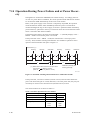
7.12 Checking Flowrate (Water Level) ................................................................ 7-15
7.13 Operation If Water Supply is Suspended ..................................................... 7-15
7.14 Operation During Power Failure and at Power Recovery............................ 7-16
7.15 Standard Formazine Solution ........................................................................ 7-17
7.15.1 Preparing 400-NTU Standard Formazine Solution ............................... 7-17
7.15.2 Preparing Standard Formazine Solution for Calibration ...................... 7-18
8.
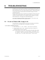
TROUBLESHOOTING .............................................................................. 8-1
8.1
8.2
9.
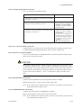
Events in Which FAIL Lamp Is Lit ............................................................... 8-1
FAIL Lamp Not Lit......................................................................................... 8-6
Spare Parts ................................................................................................... 9-1
Customer Maintenance Parts List ................................................. CMPL 12E04A03-02E
Revision Record
IM 12E04A03-023E
v
1. OVERVIEW
1.
OVERVIEW
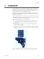
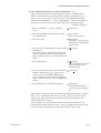
The range of applications for turbidity meters, originally used only for operation and
management of water purification plants, has recently been expanded to include such
applications as turbidity detection in chemical processes and measurements of concentration of suspended solids in a variety of industrial wastewater.
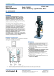
The TB450G NTU-compliant surface scattering type turbidity meter is an industrial
turbidity meter employing the Right-angled Surface Scattering-light measuring method
and has the following features:
d Incorporates a microprocessor, offering advanced performance and high reliability
d Enhanced self-diagnostics functions including lamp burn-out detection, converter
check, and upper and lower limit alarm detection
d Variable output ranges from 10 NTU to 2000 NTU
d Use of the Right-angled Surface Scattering-light measuring method means that
the optical system is free from contamination due to the suspension in the
measured water
d Features a signal smoothing function and countermeasures against bubbles to
reduce the effect from bubbles
d Extensive functions (automatic cleaning, automatic zero calibration, and more)
available with optional pinch and solenoid-operated valves added to the sampling
system
F101.EPS
Figure 1.1 TB450G NTU-compliant Surface Scattering Type Turbidity Meter
IM 12E04A03-02E
1-1
1.1
System Configuration
An NTU-compliant Surface Scattering type turbidity measuring system is usually
composed of a detector, a converter, and a sampling system that feeds the measured
water, zero calibration water, and cleaning water. The TB450G is offered not as a
system but as components, a detector and converter, and can be combined with a desired
sampling system to configure a turbidity measuring system. The inclusion of a pinch
valve and solenoid-operated valve in the sampling system provides automatic cleaning
and automatic zero calibration functions.
The following outlines typical system configurations employing a TB450G. For details
of the detector and converter, see Section 1.2.
1.1.1
Configuration with Only TB450G Converter and Detector
A system comprising only a converter and detector is the simplest possible system,
however, the following must be observed to ensure that there is no loss in the performance of the TB450G:
d The flow rate of the measured water needs to be 1.5 to 2.0 L/min at the detector.
Provide a head tank to satisfy this condition as well as to deaerate the measured
water.
d When measuring low turbidities not greater than 200 NTU, provide the specified
micro filters on the feed line of zero calibration water.
1.1.2
Configuration with Sampling System
This system is composed of a converter, a detector, and a sampling system that feeds the
measured water, zero calibration water, and cleaning water manually. This system
requires the user to manipulate hand-operated valves to feed the measured water,
perform cleaning, and perform a zero calibration. A diagram showing the recommended
piping is shown in Section 2.8.1.
The measured water is introduced to the head tank (deaeration tank) via hand-operated
valve V1. The measured water deaerated in the tank is fed to the measuring cell of the
detector at a constant flow rate of 1.5 to 2.0 L/min due to the difference in the water
head between the head tank and detector’s measuring cell. The overflow is discharged
through a drain hole.
Tap water filtrated by micro filters is used as the zero calibration water. Tap water is
introduced to the micro filters via the hand-operated valve V2. The filtrated water is
then fed to the detector’s measuring cell at a constant flow rate via the hand-operated
valve V3 and the head tank, and then discharged through the drain outlet.
Untreated tap water is used as the cleaning water. Tap water is fed from the side of the
detector’s measuring cell via the hand-operated valve V4, and a spinning flow is
generated inside the cell to wash off the suspension on the cell wall. After cleaning, the
user should open the hand-operated valve V5 situated below the head tank, to drain the
suspension of the measuring cell and head tank together with the measured water at the
same time.
1-2
IM 12E04A03-02E
1. OVERVIEW
1.1.3
Configuration with Sampling System and Automatic Cleaning System
This system is configured by assembling an automatic cleaning system to the configuration described in Section 1.1.2 immediately above. The recommended piping is shown
in the diagram in Section 2.8.2.
For automatic cleaning, the solenoid-operated valve SV2 is installed in the cleaning
water pipe as a cleaning water valve, and the pinch valve SV1 below the head tank as a
drain valve. Both SV1 and SV2 can be controlled by the automatic cleaning sequence
set in the converter to clean the detector and head tank automatically.
1.1.4
Configuration with Sampling System, Automatic Cleaning System, and Automatic
Zero Calibration System
This system is configured by assembling an automatic cleaning and zero calibration
systems to the configuration in Section 1.1.2 above. The recommended piping is shown
in the diagram in Section 2.8.3.
For automatic cleaning, the solenoid-operated valve SV2 is installed in the cleaning
water pipe as a cleaning water valve, and the pinch valve SV1 below the head tank as a
drain valve. For automatic zero calibration, the solenoid-operated valve SV4 is installed
in the zero calibration water pipe as a zero calibration water valve, and the motor valve
SV3 in the measured-water pipe as a measured water valve.
These valves can be controlled by the automatic cleaning sequence and automatic
calibration sequence set in the converter to perform cleaning of the detector’s measuring
cell and zero calibrations automatically.
IM 12E04A03-02E
1-3
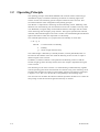
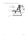
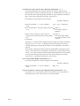
1.2
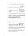
Operating Principle
The operating principle of the Model TB450G NTU-comliant surface scattered Type
turbidimeter employs a method of measuring the amount of scattering light on the
surface of water. The measuring system comprises a detector and a converter. This
section describes the meter configuration and operating principle.
The detector is composed of a measuring cell and a detecting section. Measuring water
that flows into the measuring cell from the bottom of the cell overflows at the top of the
cell. Meanwhile, a tungsten lamp closed inside the detector emits light onto the surface
of the measuring water through a group of lenses. This light is separated into scattered,
reflected, and transmitted light on the water’s surface. The transmitted light and reflected
light are absorbed in a dark area equivalent to a black body.
This scattered-light intensity (L) is proportional to the turbidity as shown here:
L=K.Q.S
where K : a constant relative to turbidity,
S
: turbidity,
Q : anount of light from the lamp.
The scattered light is detected by a turbidity element (a silicon photodiode) after it is
focused onto the element with a lens inside the detecting section in order to output a
detection signal to the converter.
In addition, a reference element is incorporated in the detecting section to hold the
amount of light (Q) from the lamp constant, and it also outputs a light-detection signal
to the converter.
The measuring circuit of the converter is in sealed housing of aluminum alloy together
with the operating panel and a terminal block for external wiring. This measuring circuit
amplifies and calculates the input from the turbidity element in the detector and outputs
a signal (1 to 5 V DC or 4 to 20 mA DC) corresponding to the measuring range.
The converter also calculates the reference element input from the detector to control the
lamp voltage so that the amount of light from the lamp is constant.
1-4
IM 12E04A03-02E
1. OVERVIEW
Display
CPU
Analog
Output
AD
Amp lifier
Lamp
Power sapply
Amp lifier
Reference
element
Turbidity
element
Lens
Scatfered
light
Lamp
Refelected
lighr
Lens
Transmitted
lighr
Drain
Measuring water
F1201.EPS
IM 12E04A03-02E
1-5
1.3
Turbidity Standard
Calibrations of the zero point and span of a turbidity meter should be performed in
reference to the following section on standard liquids.
1.3.1
Standard Water for Zero Calibration
(1) Standard Water for Zero Calibration
Tap water filtrated by a micro filter is used as the standard water for zero calibrations
(referred to as zero calibration water).
Tap water should be filtrated with a 1-micron micro filter before using it for zero
calibrations. However, if the measuring range is greater than 200 NTU, tap water filter
can be used.
Note: The zero point of the TB450G has been calibrated with tap water filtrated with a
0.1-mm micro filter at the factory before shipment.
(2) Micro Filters for Zero Calibration Water
The following shows the recommended specifications of micro filters:
1-micron micro filter
d Piping connections: Rc1/2
d Withstanding pressure: 780 kPa (8 kgf/cm2) at 40degC
d Cartridge
- Material: Polypropylene
- Minimum particle size that can be filtrated: 1 micron
d Others: With vent plug
1.3.2
Standard Water for Span Calibration
(1) Standard Water for Span Calibration
The TB450G uses a formazine solution as the standard liquid.
Note: The span calibration for the TB450G has been performed using a formazine
solution at the factory before shipment.
(2) Calibration Disk
A calibration disk used for span check during scheduled maintenance, comes with the
TB450G.
Note: The turbidity values shown on the calibration disk, which comes with a TB450G,
has been scaled for that particular TB450G after performing zero and span
calibrations. This means that the calibration disk cannot be used for another
turbidity meter. When using two or more turbidity meters, make sure that only
the disk that comes with each turbidity meter is used. Also, be extremely careful
when handling the calibration disk as damage to the surface of the disk or stains
on the disk make its use for calibrations invalid.
1-6
IM 12E04A03-02E
2. SPECIFICATIONS
2.
2.1
SPECIFICATIONS
Standard Specifications
Object of Measurement : turbidity of water in filtration plants and distribution systems,
sewage plants, rivers and general industrial processes
Method of Measurement : measurement of scattered-light
Range of measurement
: 0 - 10 NTU to 0 - 2000 NTU
Display
: 4-digit LED (display resolution of 0.01 NTU, maximum
indication of 2200 NTU)
Unit of Display
: “ NTU ”
Output Range
: selectable in 3 ranges
Remote selection / local selection (standard) (optional) Autorange / manual range (standard) (optional) (For auto-range,
therange switching point is settable) Can be set to any range
within the whole range of measurement.
(However, the span is 20 % or more of the ranges upper
setpoint limit or 10 NTU, whichever is greater).
Analog Output Signal
: 4 to 20 mA DC (load resistance of up to 550 ohms) or 1 to 5
V DC (output resistance of 100 ohms or less)
Digital Output Signal
: conforms to RS-232C interface.
Communication Specifications:
Data Format
: ASCII
Data Length
: 8 bits
Baud Rate
: 1200 bps
Parity
: No
Start Bit
: 1 bit
Stop Bit
: 2 bits
Communication Scheme: mono-directional (transmission
only), asynchronous
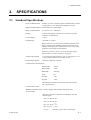
Communication Data
:
Measured Turbidity Value: converter display data (turbidity displayed value)
are transmitted.
Data part comprises 6 characters including the sign and
decimal point.
(Ex. 1) # 0050.0 CRLF
(Ex. 2) # 001.00 CRLF
(Ex. 3) # -00.50
CRLF
(Ex. 4) #_O.L_ _ CRLF
* For a “ _ _ ” (blank), a space code is transmitted.
IM 12E04A03-02E
2-1
Upper and Lower Limit Alarm Signal:
continuously transmitted when an upper or lower limit alarm
is detected.
#ALARM CRLF
Range Output Signal :transmitted once when the range is switched.
Range 1: #RANGE1 CRLF
Range 2: #RANGE2 CRLF
Range 3: #RANGE3 CRLF
Automatic Cleaning / Calibration Signal:
transmitted once at the start and again at the end of automatic
cleaning or calibration.
Note: Not transmitted if these are executed manually in the
< MAINT. > mode.
start: #CLEANING_START CRLF
end: #CLEANING_END CRLF
Maintenance / Measurement Signal:
transmitted once when mode is changed.
maintenance: #MAINTENANCE CRLF
measurement: #MEASURE CRLF
Error Signal
:continuously transmitted if a failure occurs.
If there is more than one error, they are transmitted in
succession.
#ERR ss
CRLF
ss : Error number (11, 12, 13, 14, 15, 18, 25, and 26)
(Ex. 1) #ERR11 CRLF
(Ex. 2) #ERR11 _ ERRl8 CRLF
* For a “ _ ” (blank), a space code is transmitted.
Data Update Period
: approx. 1 second
Cable Length
: up to 10m
Contact Output
: maintenance output (in maintenance)
failure output (in failure detection)
range output (corresponding to the output range selected)
(COM common)
Either upper and lower alarm (standard) or automatic calibra
tion or cleaning (optional)
2-2
IM 12E04A03-02E
2. SPECIFICATIONS
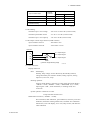
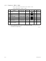
Contact
status at
power off
Non-operational
Operational
Closed
Open
Closed
Open
Closed
Open
Upper and lower limit alarm
Closed
Closed
Open
Automatic zero calibration and
automatic cleaning
Closed
Open
Closed
Type of contact output
Maintenance
Fail
Contact status at power on (Note)
Note: The contact output status at power on (open / closed) can be changed.
T21001.EPS
Contact Rating:
maximum open / close voltage
: 250 V AC or 220 V DC (resistive load)
maximum permissible current
: 2 A AC or 2 A DC (resistive load)
maximum open / close capacity
: 125 VA or 60 W (resistive load)
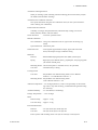
Contact Input: remote range selection (COM common)
input resistance when on
: 200 ohms or less
input resistance when off
: 100 k ohms or more
Converter
S1
R1
S2
R2
S1 : Output range 1
S2 : Output range 2
S3 : Output range 3
S3
R3
Switch
(*) Remote range-switching usage
F21001.EPS
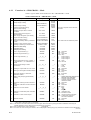
Converter Functions:
Display Functions:
Data : LED display
turbidity, lamp voltage, current detected by the turbidity element,
voltage detected by the reference element, analog output %, analog
output mA, zero error, slope
Running operation:
Lamp lit (mode display), characters in relief (other than mode display)
< MEAS. > mode, < MAINT. > mode, < PROGRAM. (1,2) > mode,
output signal “ hold ”, under calibration, in cleaning mode, error
occurrence
System operation: Characters in relief
Lamp and each solenoid valve
Maintenance Functions (< MAINT. > mode):
Zero calibration, shift calibration, span calibration, sensitivity correction
calibration, automatic cleaning manual start, automatic zero-calibration
manual start, error code display, error reset, lamp control, and reference
value calibration
IM 12E04A03-02E
2-3
Setup functions: < PROGRAM.1 > mode:
Output range setting, average coefficient setting, failure output
setting, line-segment approximation output setting, upper limit
alarm setting, lower limit alarm setting, and bubble retardant
setting
< PROGRAM.2 > mode:
Time setting for automatic cleaning, time setting for automatic
zero calibration, and selection of execution / stopping of failure
detection function
Installation location:
Indoors (for outdoor installation, separate rain-proofing measures are required).
Mounting:
Separate Detector and Converter Units
: pipe or rack mounting
Piping Connections for Detector:
Measuring water
: ID 25 mm hose connecter
Drain
: ID 25 mm hose connecter
Cable Inlet Port: 8 cable glands (bottom of the converter)
Conforming Cable OD : 6 to 12mm dia (without SV2, SV3, SV4), 6.5 to 7mm dia.
(for SV2, SV3, SV4)
Type of Wiring
: power, analog output, digital output, contact output,
contact input, output for solenoid valves (SV1 to SV4)
ground (use the converter connecting terminal ground or
ground terminal located outside the case).
Measuring Water:
With Sampling System
Flowrate
: 1.5 to 2 l/min
Temperature : 0 to 50 degC (but with ambient temperature at + 30 degC or less)
Zero-calibration water
Water Qality : 1 micron filtering water
Flowrate
: 1.5 to 2.0 l/min
Temperature : 0 to 50 degC (but with ambient temperature at + 30 degC or less)
Cleaning water : (for the system with sampling system)
Water Quality : Turbidity 2 NTU or less (tap water)
Temperature
: 0 to 50 degC (but with ambient temperature at + 30 degC or less)
Flowrate
: 3 to 6 l/min
Power Supply
: 100 / 110 V AC, 50 /60 Hz, or 200 /220 V AC, 50/60 Hz
Supply voltage:
Single Detector and Converter Units : 70 VA or less
With Sampling System
2-4
: 250 VA or less (for full loading of recom
mended automatic cleaning and zero calibration)
IM 12E04A03-02E
2. SPECIFICATIONS
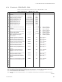
Automatic Cleaning Function:
Water jet cleaning system (cleaning time and cleaning period can be freely set)(for
the model with automatic cleaning)
Automatic-Zero Calibration Function:
Zero-point calibration using the zero-calibration water (for the system with automatic cleaning zero calibration)
Failure Detection Function:
Turbidity overrange, lamp disconnection, abnormal lamp voltage, AD circuit
failure, Memory failure, and CPU failure
Check Functions
: Converter operation check
Manual Calibration
:
Zero-Calibration : Using zero-calibration water or light source off zeroing (op
tional)
Span Calibration : Calibration plate
Other Functions
: Line-segment approximation output, upper and lower limit
alarm, and output average coefficient setting
Materials:
Detector
: Black modified polyphenylene ether (PPE) (wetted part)
Piping
: Rigid polyvinyl chloride (PVC), polyethylene, and polypropylene
(all used for wetted parts)
Mounting Frame : Carbon steel plates or stainless steel (to be specified)
Converter
: Aluminum alloys casting
Coating Finish:
Converter
: Polyurethane resin baked coating finish; Color: Munsell
0.6GY3.1 / 2.0 and Munsell 2.5Y8.4/ 1.2
Mounting Frame : Polyurethane resin baked coating finish
Color: Munsell 0.6GY3.1 / 2.0
Ambient Temperature: - 5 to 50 degC (However, if this is the possibility of the measuring water or tap water freezing, countermeasures against freezing
are necessary)
Ambient Humidity
: 5 to 95% RH (no condensing)
Storage Temperature : - 30 to 70 degC
Mass:
Detector body
: Approx. 3.5 kg
Converter body : Approx. 9.5 kg
External Dimensions:
Detector
: 316 (W) X 285 (H) X 200 (D) mm
Converter
: 260 (W) X 340 (H) X 150 (D) mm
Entire system with mounting frame: 530 (W) X 1450 (H) X 550 (D) mm
IM 12E04A03-02E
2-5
2.2
Characteristics
Linearity: When the upper limit value of span is 1000 NTU or less; 62% of the range
upper limit.
When the upper limit value of span is 2000 NTU or less; 65% of the range
upper limit.
Repeatability: 2% of the range upper limit.
Warm-up Time: Approx. 30 minutes
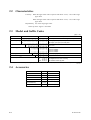
2.3
Model and Suffix Codes
[Style : S1]
Model
Suffix Codes
Option Codes
TB450G
Description
NTU-compliant Surface Scattered Type Turbidity Meter
Measuring Range
-L
Low range (0 to 0.1) to (0 to 100) NTU
-H
Output
High range (0 to 10) to (0 to 2000) NTU
-4
-5
4 to 20 mA DC
1 to 5 V DC
Power Supply
-1
-3
-6
-7
Sampling System
100V AC, 50/60Hz
110V AC, 50/60Hz
200V AC, 50/60Hz
220V AC, 50/60Hz
-NN
None sampling system (Note 1)
-NN
Optional Specification
Always -NN
/P
/R
/SCT
Mounting Bracket for Pipe mounting
Mounting Bracket for Rack mounting
With Stainless Steel Tag-plate
(Note 1) Provide head tank (defoaming tank) so that the flow rate of the water sample reaches the specified flow (1.5 to 2 l/min).
T23001.EPS
2.4
Accessories
Name
Q'ty
Calibration Disk
1
Silicon Cloth
1
Remark
In converter
Lamp
2
Fuse
4 each
Soft PVC Tube
(ø33 Xø25 Black)
1 set
For detector piping
(1m X 2)
Clamp
2
Spare
1A, 3A (Spare)
For detector piping
T24001.EPS
2-6
IM 12E04A03-02E
2. SPECIFICATIONS
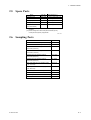
2.5
Spare Parts
Name
Part No.
Recommend (*1)
K9412AK
1 time / half a year (*2)
1 micron Filter
K9008ZD
1 time / year
Fuse (1A)
A1109EF
1 time / year
Fuse (3A)
A1094EF
1 time / year
Soft PVC Tube 2m
(ø33 Xø25 Black)
K9411ZF
1 time / year
Change Lamp
(*1) Recommended replace period depends on application
condition.
(*2) Please change soon when lamp disconnection (Err12)
or lamp life error (Err25) is appeared.
T25001.EPS
2.6
Sampling Parts
Name
Part No.
Pinch Valve for Drain water (100, 110V AC)
K9411JG
Pinch Valve for Drain water (200, 220V AC)
K9411JH
Solenoid Valve for Cleaning water or
A1113MV
Zero water (100V AC)
Solenoid Valve for Cleaning water or
A1115MV
Zero water (110V AC)
Solenoid Valve for Cleaning water or
A1114MV
Zero water (200V AC)
Solenoid Valve for Cleaning water or
A1116MV
Zero water (220V AC)
Motor Operated Valve for Sampling water
K9411VE
(100, 110V AC)
Motor Operated Valve for Sampling water
K9411VF
(200, 220V AC)
Head Tank (With Manual Valve)
K9411GC
Head Tank (With Pinch Valve 100, 110V AC)
K9411JA
Head Tank(With Pinch Valve 200, 220V AC)
K9411JB
Mounting Bracket for Head Tank
K9411BB
T26001.EPS
IM 12E04A03-02E
2-7
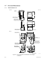
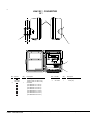
2.7
External Dimensions
2.7.1
TB450G-#-#-#-NN-NN
Converter
Unit : mm
202
56
2B pipe
(ø60.5)
340
Pipe mounting
bracket (optional)
Wiring inlet port
(Waterproof glands
for OD 6 to 12mm)
260
150
158
126.5
Rack mounting
bracket (optional)
33
150
238
4-ø6holes
Detector
245
2B pipe (ø60.5)
(30)
250
208
310
150
Pipe mounting
material (optional)
48
170
145
Inlet for
Cleaning water
Water sample Inlet,
25øi.d. hose joint
Water sample outlet,
25øi.d. hose joint
(30)
10
105
120
Rack mounting
material (optional)
25
170
190
3-ø6 holes
F27101.EPS
Figure 2.1 External Dimensions of the TB450G-L Scattered-light
Turbidimeter
2-8
IM 12E04A03-02E
2. SPECIFICATIONS
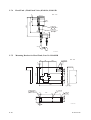
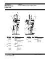
2.7.2
1 micron filter with case (Part No. K9411UA)
Unit : mm
115
OUT
Exit
Rc1/2
Entrance
Rc1/2
121
316
294
Cartridge
F27201.EPS
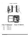
2.7.3
Head Tank (With Manual operated Valve) ; K9411GC;
37.5
171.1
V5
125
288
352.5
207.5
165
F27301.EPS
IM 12E04A03-02E
2-9
Head Tank (With Pinch Valve) K9411JA, K9411JB
Unit : mm
171.1
165
170
374.5
467.5
37.5
2.7.4
Tube size
33X 25
70
Tube size
22X 15
175
SV1
F27401.EPS
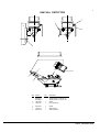
2.7.5
Mounting Bracket for Head Tank; Part No. K9411BB
40
90
100
Unit : mm
6- 6.2hole
5
40
90
180
230
41 18
5
300
2- 6.2hole
2-M5(Surface)
2- 6.2hole
(Surface / Back)
160
110
4- 6.2hole
(Both side)
80
50 15
15
25
2-10
30
F27501.EPS
IM 12E04A03-02E
2. SPECIFICATIONS
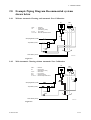
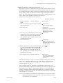
2.8
Example Piping Diagram Recommended systems
shown below
2.8.1
Without Automatic Cleaning and Automatic Zero Calibration
HT
CELL
HT
:
:
CELL
Detector
Head Tank
(Defoaming Tank)
Zero Filter
Manual Operaled Valve
F1,F2
:
V1 to V5 :
V5
Sampling Water (VP16)
V1
Tap Water (VP16)
V3
V2
F1
1 micron
filter
V4
Drain Water (VP40)
F28101.EPS
Figure 2.5
2.8.2
With Automatic Cleaning without Automatic Zero Calibration
HT
CELL
HT
:
:
F1,F2
:
SV1
:
SV2
:
V1 to V4 :
CELL
Detector
Head Tank
(Defoaming Tank)
Zero Filter
Pinch Valve
Solenoid Valve
Manual Operaled Valve
SV1
Sampling Water (VP16)
SV2
V1
Tap Water (VP16)
V3
V2
F1
1 micron
filter
V4
Drain Water (VP40)
F28201.EPS
Figure 2.6
IM 12E04A03-02E
2-11
2.8.3
With Aotomatic Cleaning and Automatic Zero Calibration
HT
Detector
Defoaming Tank
Zero-turbidity filter
Motor-operated valves
Solenoid valves
Hand-Operaled Valve
Measuring Water (VP16)
:
M
:
:
:
:
:
:
M
CELL
HT
F
SV1,SV3
SV2,SV4
V1 to V4
CELL
SV3
SV1
SV2
V1
Tap Water (VP16)
V2
V3
SV4
F1
1 micron
filter
V4
Drain (VP40)
F28301.EPS
Figure 2.7
2-12
IM 12E04A03-02E
2. SPECIFICATIONS
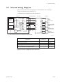
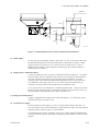
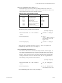
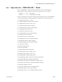
2.9
Internal Wiring Diagram
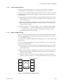
Figure 2.8 shows the internal wiring diagram of the turbidimeter with a sampling
system. For external wiring, see Section 3.3.
A dedicated cable is shipped connected to the detector.
Detector
Dedicated cable
Valves
S1
V1
S2
S2
V2
V+
V+
V3
V3
V-
V-
V4
0
AG
AG
V5
S
V6
C
1
S1
Turbidity
element
Converter
Reference
element
V1
P1
P1
V7
P2
P2
V8
2
V9
1
G L1 L2 V10
2
Lamp
*1
SV1
Drain
(Pinch valve)
SV3
Measuring water
(Motor-operated
valve)
SV2
Cleaning Water
(Solenoid valve)
SV4
Tap Water
(Solenoid valve)
(*1) Valve connections vary with the specifications as shown below.
F29001.EPS
Configuration
Diagram of
Recommended Piping
Valves Used
None
Only converter and detector
With sampling system
See Section 2.8.1
None
With sampling system and automatic cleaning system
See Section 2.8.2
SV1, SV2
With sampling system, automatic cleaning
system, and automatic zero calibration system
See Section 2.8.3
SV1, SV2
SV3, SV4
T29001.EPS
Figure 2.8 System configuration and Connections
IM 12E04A03-02E
2-13
3. INSTALLATION, PIPING, AND WIRING
3.
INSTALLATION. PIPING. AND
WIRING
3.1
Installation
3.1.1
Unpacking
The NTU-compliant surface scattered type turbidimeter is shipped after being sufficiently packed so as not to be damaged during transportation. When the turbidimeter is
delivered, unpack the meter carefully. If the turbidimeter with a sampling system is
delivered, unpack them near the location where they are to be installed.
3.1.2
Installation Location
The NTU-compliant surface scattered type turbidimeter should be installed in a location
where:
(1) rainwater cannot get inside, such as in a building or a cubicle,
(2) there is little vibration,
(3) there are few corrosive gases,
(4) there is not much humidity,
(5) there is little temperature change and the temperature is maintained around normal,
(6) there is enough clearance for maintenance and maintenance work can be easily done,
(7) drain-off can be well provided.
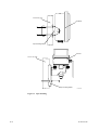
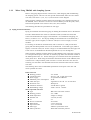
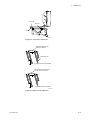
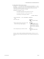
3.1.3
Installation
Installation of the NTU-compliant surface scattered type turbidimeter need to mount the
detector and converter onto pipes (nominal diameter of 50 mm) or racks with the special
mounting bracket. Note that these brackets are only supplied when the user has specified
them.
IM 12E04A03-02E
3-1
50-mm dia. pipe
Conberter
Pipe mounting braket
Detector
50-mm dia. pipe
Pipe mounting braket
F31301.EPS
Figure 3.1 Pipe Mounting
3-2
IM 12E04A03-02E
3. INSTALLATION, PIPING, AND WIRING
Unit : mm
Conberter
238
126.5
4-M5
Mounting dimensions
Rack mounting
braket
M5 mounting
screw (5mm)
(4 places)
Detector
Rack mounting
braket
190
105
Mounting dimensions
3-M5
M5 moumting screw (5 mm) (3places)
F31302.EPS
Figure 3.2 Rack Mounting
IM 12E04A03-02E
3-3
3.2
Piping
3.2.1
When Using TB450G Converter and Detector Alone
(1) Piping for Measured Water
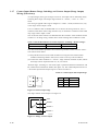
To meet the requirement of the flow rate (1.5 to 2.0 L/min), provide a head tank that
also works as a deaeration tank (constant-level tank) and connect the measured water
supply to the head tank. The head tank needs to be installed at an adequate height so as
to regulate the flow rate between 1.5 and 2.0 L/min. Refer to figures 3.3 and 3.4, which
show the structure of a head tank and the relationship between the positions of the head
tank and detector.
For the piping between the head tank and detector, use the black soft PVC tube (O.D. 33
/ I.D. 25 mm) that comes with the TG450G. Prevent clogging and bubbles from
collecting inside the tube, by cutting the tube to an adequate length to ensure that no
bends occur or water or bubbles become trapped.
90
Head Tank Cover
40
ø165
Inlet
I.D.approx.22mm
Overflow
I.D.48mm
ø154.8
ø51
Hole for Air Exhaust
ø15
Outlet
I.D.approx.48mm
205
195
160
128
105
26
175
To Detector
for I.D.25mm
hose connecter
Measuring Water Inlet
Overflow outlet
for I.D.25mm Tube
I.D.ø15mm for Tube
Outlet
I.D.ø19mm
for Silicon tube
F32101.EPS
Figure 3.3 External Dimensions of Head Tank
3-4
IM 12E04A03-02E
3. INSTALLATION, PIPING, AND WIRING
Overflow
(16.5)
87.5 }2
i128 j
(15)
(50)
(50)
F32102.EPS
Figure 3.4 Relationship between Positions of Head Tank and Detector
(2) Drain Piping
Connect the piece of the black soft PVC tube (O.D. 33 / I.D. 25 mm) that comes with
the TG450G, and place the other side of the tube in a drain ditch or the like. When
laying the tube, be careful to lay it in such a way that no bends occur or water or
bubbles become trapped. Water trapped in the drain pipe may cause the detector’s
measuring cell to overflow.
(3) Piping for Zero Calibration Water
As the zero calibration water, tap water is filtrated and fed to the detector. As with the
measured water, the zero calibration water must also be connected to the head tank to
meet the requirement of the flow rate of the water fed to the detector. Provide a
switching valve on the inlet of the head tank (described in Item (1)) and connect the
zero calibration water pipe to the valve so as to allow feed to the head tank to be
switched over between the measured water and zero calibration water.
To use tap water for zero calibrations, it should be filtrated with a 1 micron micro filter.
However, if the measuring range is greater than 200 NTU, tap water can be used. For
the specifications required for the micro filters, see Section 1.3.
(4) Piping for Cleaning Water
A plug is equipped at the cleaning water inlet of the detector. For connection of the
cleaning water pipe, see Section 3.2.2.
(5) Precautions for Piping
For all connections to the detector, be sure to use the black soft PVC tube (O.D. 33 /
I.D. 25 mm) that comes with the TG450G, to shield them from light. For other portions
of piping, hard or soft PVC pipes are recommended.
For measured-water and zero calibration water pipes, avoid clogging and bubbles from
collecting inside the pipes by preventing, as much as possible, kinks or water becoming
trapped.
IM 12E04A03-02E
3-5
3.2.2
When Using TB450G with Sampling System
Refer to the piping diagram shown in Section 2.8, when designing and manufacturing
the sampling system. Be sure to at least provide the head tank, filters for zero calibration water, and valves V1, V2, V3, V4, and V5 shown in this diagram.
When using the automatic cleaning function and automatic zero calibration function of
the TB450G, refer to Sections 2.8.2 and 2.8.3 and in addition provide the pinch, motor,
and solenoid-operated valves shown as SV1, SV2, SV3, and SV4.
The following describes the precautions for each pipe.
(1) Piping for Measured Water
Piping for measured water denotes piping for feeding the measured water to the detector.
Provide a head tank that also works as a deaeration tank (constant-level tank) and
connect the measured water supply to the head tank. For installation and piping, see
Item (1) in Section 3.2.1. For the pipe leading the measured water to the head tank, a
hard PVC pipe (VP16 or higher) or soft PVC tube (I.D. 15 mm or larger) is recommended.
For cleaning of the detector and head tank, refer to Section 2.8.1 and provide drain
piping with the hand-operated valve V5 for the head tank. A hard PVC pipe (VP25 or
higher) or soft PVC tube (I.D. 25 mm or larger) is recommended for the drain pipe, and
a ball valve is recommended for the hand-operated valve (V5 in the diagram).
When using the automatic cleaning function of the TB450G, refer to Sections 2.8.2.and
2.8.3 and provide the pinch valve SV1 for the drain pipe below the head tank instead of
the hand-operated valve V5. For the drain pipe, use a tube that meets the specifications
of the pinch valve. When using the automatic calibration function of the TB450G, refer
to Section 2.8.3 and provide the pinch valve SV1 as well as the motor valve SV3 for
switching over the feed to the head tank between the measured water and zero calibration water.
The following shows the recommended specifications of the pinch valve SV1 and
motor-operated valve SV3:
Pinch
d
d
d
d
d
d
d
d
valve SV1
Working pressure
Connection tubes
Power supply
Maximum power consumption
Cable inlet port
Protection class
Insulation resistance
Withstanding voltage
Motor-operated valve SV3
d Type
d Working pressure
d Fluid temperature
d Nominal size
d Cv
d Process connections
d Rated torque
d Open-close time
d Motor type
d Motor protection
3-6
: 0 to 10 kPa
: O.D. 23 / I.D. 19 mm silicon tube
: As specified for TB450G
: 60 W
: Applicable to an O.D. 6 to 12 mm cable
: Waterproof
: 100 M ohms or greater
: 1000 V AC for 1 minute
: Ball valve with motor actuator
: 0 to 1 MPa
: 0 degC to 50 degC
: 1/2 inch (15 mm)
: 12
: TS sockets
: 3 N·m (30 kg·cm)
: 4.5 to 5.4 seconds
: Inductor synchronous motor
: With built-in thermal protector
IM 12E04A03-02E
3. INSTALLATION, PIPING, AND WIRING
d
d
d
d
d
Power supply
Maximum power consumption
Cable inlet port
Protection class
Materials
- Body and ball
- Sheet
- Seal
d Ambient temperature
: As specified for TB450G
: 14 VA or 8 W
: Applicable to an O.D. 6.5 to 7 mm cable
: Rainproof for outdoor-use
: Hard PVC
: PTFE
: EPDM
: –20 degC to 60 degC
(2) Piping for Tap Water
Piping for tap water denotes piping for feeding cleaning water and zero calibration water
to the detector.
Use tap water as the cleaning water. Connect polyethylene or polypropylene tubes of
O.D. 8 mm and I.D. 6 mm to the Rc1/4 cleaning water ports on the sides of the detector
using adequate fittings. When using the automatic cleaning function of the TB450G,
refer to Sections 2.8.2.and 2.8.3 and provide the solenoid-operated valve SV2 for the
cleaning water pipe.
Tap water filtrated by micro filters is used as the zero calibration water. For the piping
method, see Item (3) in Section 3.2.1. When using the automatic calibration function of
the TB450G, refer to Section 2.8.3 and provide the solenoid-operated valve SV4 in the
zero calibration water pipe.
Note: Do not use transparent or semitrans parent fittings for connecting tubes to the
detector.
The following shows the recommended specifications of solenoid-operated valves SV2
and SV4:
Solenoid valves SV2/SV4
d Type
: Two-port solenoid-operated directional valve
d Applicable fluid
: Water
d Working pressure
: 0 to 1.5 MPa
d Withstanding pressure
: 5.0 MPa (water)
d Fluid temperature
: 1 to 60 degC
d Cv
: 0.8
d Process connections
: Rc3/8
d Power supply
: As specified for TB450G
d Maximum power consumption : 7.5 VA
d Cable inlet port
: Applicable to an O.D. 6.5 to 7 mm cable
d Protection class
: Waterproof
d Materials
- Body
: Brass or stainless steel
- Sheet
: Nitrile rubber
d Ambient temperature: –20 degC to 60 degC
For the pipe of the tap water supply, a hard PVC pipe (VP16 or higher) or soft PVC
tube (I.D. 15 mm or larger) is recommended.
(3) Drain Piping
Drain piping denotes piping for discharging the measured water and tap water from the
detector to a drain ditch or the like. When laying piping, be careful that no bends occur
or water or bubbles become trapped as this may cause deposit to build up or a delay in
the flow to occur in the piping. For the drain pipe, a hard PVC pipe (VP40 (VU40) or
higher) is recommended.
IM 12E04A03-02E
3-7
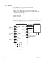
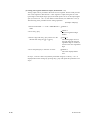
3.3
Wiring
There are the following categories for wiring to the turbidimeter:
(1) Wiring for detector and conveter
(2) Wiring converter and valves (SV1,SV2) when automatic cleaning added
(3) Wiring converter and valves (SV1,SV2,SV3,SV4) when automatic cleaning and
automatic zero calibration added
(4) Wiring for power supply and grounding
(5) Analog output wiring
(6) Digital output wiring
(7) Contact input (remote range selection) wiring and contact output (range output)
wiring (if necessary)
(8) Contact output (maintenance, failure, upper and lower limit alarms, or automatic zero
calibration / cleaning outputs) wiring (if necessary)
Turbidity converter
Receiving instrument
G
R1 REMOTE
RANGE
R2
Remote range
selection
contact input
Analog output wiring
ANALOG 1
OUTPUT
2
M1
R3
MAINT
M2
1
2
Maintenance
contact output
G
A1
F1
Range contact
output
A2 ANSWER
BACK
A3
FAIL
F2
To power supply
C1
AUX
A4
C2
TD
Digital output
(RS-232-C)
RD
Failure contact
output
DIGITAL
OUTPUT
Upper and lower limit alarm
or automatic cleaning and
zero-calibration contact
output
DG
G
Ground
POWER
L1
L2
To power supply
F33001.EPS
Figure 3.5 Wiring Diagram
3-8
IM 12E04A03-02E
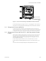
3. INSTALLATION, PIPING, AND WIRING
Wiring terminal block
External wiring cable
connection (5 places)
F33002.EPS
Figure 3.6 Converter External Wiring Terminal Block and Cable Connections
For each cable wiring, refer to figure 3.5 and 3.6 “ wiring diagrams ” in the section 2.9.
Note: Be sure to insert cable glands with blind plugs into the unused cable connections.
3.3.1
Wiring between Converter and Detector
Connect the converter to the detector with the dedicated cable that was already connected to the detector when it was delivered. Remove the drip-proof cap plug capped in
a cable gland of the converter, and connect the other side of the cable to the converter.
3.3.2
Wiring between Converter and Valves SV1/2 – when Using Automatic Cleaning
Function
When using the automatic cleaning function, wiring from converter to the pinch valve
SV1 (drain valve) and solenoid-operated valve SV2 (cleaning water valve) must be
performed. Remove the drip-proof cap plugs capped to the cable glands of the converter, and perform the wiring.
For the wiring to the pinch valve SV1, use a 2-core cable of O.D. 6 to 12 mm.
For the wiring to the solenoid-operated valve SV2, use a 2-core cable of O.D. 6.5 to 7
mm.
Note: Do not remove the drip-proof plugs from cable glands that are not used.
IM 12E04A03-02E
3-9
3.3.3
Wiring between Converter and Valves SV1/2/3/4 – when Using Automatic Cleaning Function and
Automatic Zero Calibration Function
When using the automatic cleaning function, the wiring from the converter to the
following valves must be performed with the respective cables:
d Pinch valve SV1 (drain valve), with a 2-core cable of O.D. 6 to 12 mm
d Solenoid-operated valve SV2 (cleaning water valve), with a 2-core cable of O.D.
6.5 to 7 mm
d Motor-operated valve SV3 (measured water valve), with a 3-core cable of O.D.
6.5 to 7 mm
d Solenoid-operated valve SV4 (zero calibration water valve), with a 2-core cable
of O.D. 6.5 to 7 mm
Remove the drip-proof cap plugs capped to the cable glands of the converter, and
perform the wiring.
For the wiring to motor valve SV3, be careful with the connections to the converter
terminals V4 (open), V5 (shut), and V6 (common). The voltages output from these
terminals are as follows:
d When opening SV3
d When shutting SV3
–
V4–V6: Power supply voltage
–
V5–V6: 0 V
–
V4–V6: 0 V
–
V5–V6: Power supply voltage
Check the specification of the motor valve and perform correct wiring.
3.3.4
Power and Grounding Wiring
[Power Wiring]
This is the wiring to supply power, conforming to the frequency and voltage specifications, to the converter. Connect converter terminals L1 and L2 with the power supply.
Use a two-conductor cable having a finished OD of 6 to 12 mm for the power wiring.
The cable end-treatment procedure for the end to be connected to the converter is
described in the following:
(1) Strip off about 80 mm of the cable insulation covering from the end.
(2) Attach clamp terminal lugs fitted to M4 (4 mm) screws to the tips of the conductors.
[Grounding Wiring]
Do the grounding wiring using the grounding terminal at the bottom of the converter
case. As the grounding terminal is for an M5 (5 mm) screw, connect a grounding
conductor whose end is end-treated (obtaining sufficient continuity) and do the grounding (JIS class 3, grounding resistance of 100 OHMS or less).
Note: If grounding cannot be done using the ground terminal of the converter case,
connect the grounding conductor to terminal G (M4 (4 mm) screw) within the
converter and ground the conductor on the power supply side. In this case, use 3conductor or 2-conductor shielded cables for the power and grounding wiring.
3-10
IM 12E04A03-02E
3. INSTALLATION, PIPING, AND WIRING
3.3.5
Analog Output Wiring
This is the wiring for transmitting a 1 to 5 V DC or 4 to 20 mA DC output signal
corresponding to the output range to a receiving instrument such as a recorder.
For wiring, use a 2-conductor shielded cable of finished OD 6 to 12 mm. The cable endtreatment procedure and connection procedures on the connecting side to the converter
are shown below.
(1) Strip off about 40 mm of the insulation covering and shield from the cable end and
solder a leadwire to the root of the exposed shield. Protect the soldered part with
wound insulation tape.
(2) Make the soldered leadwire length almost the same as other conductor lengths and
attach crimp terminal lugs conforming to an M4 (4 mm) screw to the tips of each
conductor and this leadwire.
(3) Connect the cable to the converter terminals + and -. Connect the plus pole conductor to the OUTPUT “ + ” terminal and the minus pole conductor to the OUTPUT
“ - ” terminal. Also, connect the leadwire of the shield to terminal G. (Do not
ground the shield on the receiving side.)
3.3.6
Digital Output Wiring
This is the wiring for outputting turbidity signals and generated failure details as digital
signals (through RS232-C). For details of specifications and transmission, see Section
2.1, “ Standard Specifications ”.
For wiring, use a 3-conductor shielded cable of finished OD 6 to 12 mm. Limit the cable
length up 10 m.
The cable end-treatment procedure and connection procedures on the connecting side to
the converter are shown below.
(1) Strip off about 40 mm of the insulation covering and shield from the cable end and
solder a leadwire to the root of the exposed shield. Protect the soldered part with
wound insulation tape.
(2) Make the soldered leadwire length almost the same as other conductor lengths and
attach crimp terminal lugs conforming to an M4 (4 mm) screw to the tips of each
conductor and this leadwire.
(3) Connect the cable to the converter terminals (TD, RD, DG, and G). Connect the
conductors as shown in Figure 3.7. (Do not ground the shield on the receiving side).
Converter
Receivine equipment
TD
TD
RD
RD
DG
DG
Shield
G
TM1
G
F33601.EPS
Figure 3.7 Wiring diagram for digital output
IM 12E04A03-02E
3-11
3.3.7
Contact Input (Remote Range Swtiching) and Contact Output (Range Output)
Wiring (If necessary)
As output ranges, three types of ranges can be set, and output can be obtained by freely
switching these ranges. The output range selection is “ remote”, “ local ” or “ auto ”
mode.
This wiring is applied if the range is changed in “ remote ” mode (see Section 6.6 (12))
or the range contact output is used.
Use a 2-conductor cable of finished OD 6 to 12 mm for the wiring. However, use a 3conductor cable when remote range selection only is used and a 4-conductor cable when
only range contact output is used.
The on and off contact statuses are identified with the resistance value conditions shown
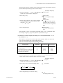
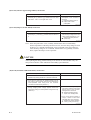
in Table 3.1. In doing wiring, confirm that a contact meeting these conditions is used.
Table 3.1 On/off Identification of Contact Input for Switching “ Remote Range”
On status identification
Off status identification
200 Ω or less
Resistance value (contact)
100 kΩ or more
T33401.EPS
The cable end-treatment procedure and connection procedures on the converter connection side are shown below.
(1) Strip off about 40 mm of the cable insulation covering from the end and attach
suitable terminal lugs fitted to M4 (4 mm) screws to the tip of each conductor.
(2) Connect the cable conductors to “ remote ” range selection terminals R1, R2, and R3
and range contact output terminals A1, A2, A3 and A4.
“Remote range” switching on / off contact input is performed between terminals R1 and
R2, and between terminals R1 and R3 (See figure 3.9). The relationship between the on
/ off contact input and the output range is as shown in Table 3.2.
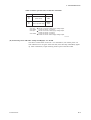
Table 3.2 Contact Input and Output Range
R1
R2
R3
R1-R2
R1-R3
Output range
OFF
OFF
RANGE 1
ON
OFF
RANGE 2
OFF
ON
RANGE 3
T33402.EPS
F33401.EPS
Figure 3.8 contact output range
The range contacts can be output as in Figure 3.9.
A1
COM
A2
RANGE 1
A3
RANGE 2
A4
RANGE 3
F33402.EPS
Figure 3.9 Range Contact Output
3-12
IM 12E04A03-02E
3. INSTALLATION, PIPING, AND WIRING
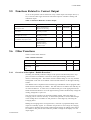
3.3.8
Contact Output (During maintenance, failure, upper or lower limit alarm, during
automatic cleaning, during automatic zero calibration) Wiring (If necessary)
The converter outputs contact signals for failure, maintenance, and upper and lower limit
alarm or automatic cleaning / in calibration. Use a finished OD 6 to 12 mm cable for
this wiring (select a 2-, 3-, or 6-conductor cable depending on the number of contact
outputs used). The contact rating for contact output relays is as shown in Table 3.3. For
the instrument to be connected, select that which satisfies the conditions in Table 3.3.
Table 3.3 Contact Rating for Contact Output Relay
DC relay
AC relay
Maximum permissible contact voltage
220 V
250 V
Maximum permissible contact current
2A
2A
Maximum permissible contact power
60 W
125 VA
T33801.EPS
Connect each conductor of the cable to terminals F1, F2, M1, M2, C1, and C2 respectively. Before connection, end-treat the cable conductors. Strip off the cable insulation
covering by about 40 mm and attach crimp terminal lugs conforming to M4 (4 mm)
screws to each conductor.
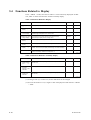
Table 3.4 shows the operation of each contact output.
Table 3.4 Contact Output Operation
Contact
M1, M2
F1, F2
C1, C2 (*1)
Operation
Closed (setting upon shipment from the factory) for maintenance
(other than the < MEAS. > mode). (*2)
Open when a failure occurs (setting upon shipment from the factory). (*2)
Open when the upper or lower alarm is generated (at shipment from the
factory). (*2)
or
Closed during automatic calibration or automatic cleaning. (*2)
(*1) Contacts C1 and C2 can be used in two ways: for upper and lower limit alarms and for
automatic cleaning and calibration. These can be selected with FUNCTION " E " in the
< PROGRAM1 > mode. When shipped from the factory, this is set for the upper and
lower alarms.
(*2) Either open or closed can be selected when the contact operates.
Set them with FUNCTIONs " C " to " F " in the < PROGRAM2 > mode.
T33802.EPS
IM 12E04A03-02E
3-13
4. OPERATION
4.
4.1
OPERATION
Preparation for Operation
For preparation, proceed with the work in turn according to the items in subsections
4.1.1 to 4.1.10.
Since the types and number of valves vary with the specifications for sampling, see the
piping diagrams in Section 2.8. For meaning of the codes, see Section 2.3.
CAUTION
When the detector is opened for preparation, take extreme care not to get the lenses in
the detector (in two places) dirty. If they get dirty, clean the lenses (see Section 7.8).
4.1.1
Checking Piping and Wiring Conditions
Examine that the piping and wiring have been done properly.
4.1.2
Supplying Power
First confirm that the power supply is of the voltage andfrequency that meet the specifications. Also, check that the cap of the fuse holder in the converter is securely tightened.
Turn on thepower switch in the converter.Then, press the [MODE] key on the converter
to go to the <MAINT.> mode.
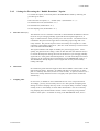
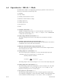
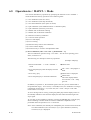
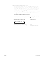
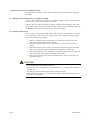
4.1.3
Setting Sampling Specification
To enable the automatic cleaning and zero calibration functions, the FUNCTION “ 9 ”
setting in the section 6.6 (22) <PROGRAM1> mode must be made according to the
specifications of the sampling system assembled with the TB450G, as follows:
1) Press the [MODE] key of the converter to change the mode to <PROGRAM1>,
and call FUNCTION “ 9. ”
2) The code currently set is then displayed (“____1” for example).
3) According to the specifications of the sampling system used, change the code as
necessary using the [>] key and press the [ENT] key to set the code.
d Code ____1:
When using a TB450G converter and detector solely or when
assembling it with a simple sampling system as shown in Section 2.8.1.
d Code ____2:
When assembling a TB450G converter with an automatic
sampling system as shown in Section 2.8.2.
d Code ____3:
When assembling a TB450G converter with automatic
sampling and zero calibration systems as shown in Section 2.8.3.
4) Press the [MODE] key to change the mode to <MAINT.>.
Note 1: Be sure to set the correct code that meets the specifications of the sampling
system used. Otherwise, correct turbidity measurements may not be performed.
IM 12E04A03-02E
4-1
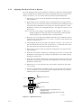
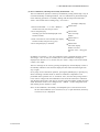
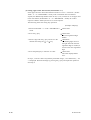
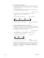
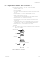
4.1.4
Feeding Zero Calibration Water
1) Feed the tap water to the zero-turbidity filters.
2) Shut all valves except V2 and SV4.
Note 1: SV4 exists only when automatic calibration is used (see Sections 2.8.1 and
2.8.2).
Note 2: Use the valve operation key of the converter to manipulate SV1, SV2, SV3,
and SV4.
3) Loosen the vent plugs at the top of zero-turbidity filters and vent them until tap
water overflows from them. Then, tighten the plugs.
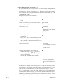
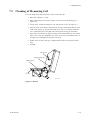
4) Loosen screw A at the lower part of the detector and open the upper part as
shown in Figure 4.1.
5) Open V3 and feed the zero calibration water to the head tank (deaeration tank).
Adjust the opening level of V3 so that the feed flow rate of the zero calibration
water to the head tank may be regulated at 2 to 3 L/min. See note 3 below for
how to check the flow rate.
Note 3: how to check flow rate of feed to head tank: Fully open valve V5 or SV1
below the head tank and measure the amount of discharge from the tank’s
drain outlet for 1 minute using a graduated measuring cylinder or beaker.
Be sure to shut the valve after checking the discharge flow rate.
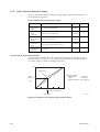
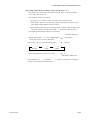
6) Check whether the flow rate of feed to the detector is within 1.5 to 2 L/min. If
the flow rate exceeds this range, adjust it according to the procedure described in
Section 4.1.5. See note 4 below for how to check the flow rate of feed to the
detector.
Note 4: how to check flow rate of feed to detector: While feeding the measured
water or zero calibration water to the detector, disconnect the pipe from the
measured water outlet of the detector and measure the amount of discharge
from the outlet for 1 minute using a graduated measuring cylinder or beaker.
Be sure to connect the pipe to the detector’s outlet again after checking the
discharge flow rate.
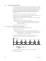
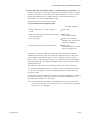
Before operation, always check the flow rate of feed to the detector as
above.
For a flow rate check at regular maintenance, visually check that there are
no ripples on the water surface as shown in Figure 4.2 (b).
4-2
IM 12E04A03-02E
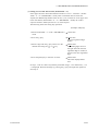
4. OPERATION
Screw B
Screw C
Screw A
F41401.EPS
Figure 4.1 Lower Part of Detector
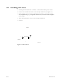
There are ripples on the
measuring surface.
Measuring cell
(a) Measurement is impossible.
The measuring surface is as
smooth as a mirror finish.
(b) Measurement is possible.
F41402.EPS
Figure 4.2 Water Level of Detector
IM 12E04A03-02E
4-3
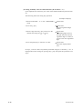
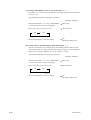
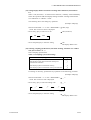
4.1.5
Adjusting Flow Rate of Feed to Detector
Flow rate adjustment has been performed for the detector at the factory before shipment.
If flow rate adjustment is required as the result of checking the flow rate of feed to the
detector in Section 4.1.4, carry out the follow procedure to perform adjustment.
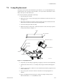
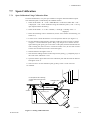
1) Open valve V5 or SV1 below the head tank to discharge water from the head
tank and detector.
2) When neither the zero calibration water nor measured water is being fed to the
detector, place a level at the drain outlet of the measuring cell and adjust the level
by means of the 4 adjustment screws (shown as C and B in Figure 4.1) so that
the detector is level in two orthogonal directions. See Figure 4.3 for how to turn
these screws.
Note 1: If a level is not available, visual adjustment is acceptable. In this case, it
should be adjusted so that water spills out from the drain outlet uniformly
when feeding the zero calibration water or measured water.
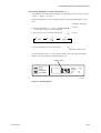
3) Shut valve V5 or SV1 below the head tank and feed the zero calibration water or
measured water to the head tank at 2 to 3 L/min. For how to check the flow rate,
see note 3 in Section 4.1.4.
4) Check whether the flow rate of feed to the detector is within 1.5 to 2 L/min. For
how to check the flow rate, see note 4 in Section 4.1.4. If the flow rate exceed
this range, follow the steps below to adjust the flow rate.
5) Open valve V5 or SV1 below the head tank and discharge water from the head
tank and detector.
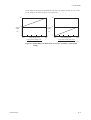
6) If the flow rate of feed to the detector’s measuring cell is below 1.5 L/min, lower
the detector’s measuring cell by turning the 4 adjustment screws while ensuring
the detector remains level.
7) If the flow rate of feed to the detector’s measuring cell is beyond 2.0 L/min, raise
the detector’s measuring cell by turning the 4 adjustment screws while ensuring
the detector remains level.
8) Repeat steps 3 to 6 above until the flow rate of feed to the detector falls within
1.5 to 2 L/min.
9) After flow rate adjustment is finished, turn the 2 screws B (left screws in Figure
4.1) by 2 rotations to lower that side, and then tighten their lock nuts when the
measuring cell is in an inclined position.
Measurement cell
Adjustment screw
Lock nut
First loosen the lock nut and then turn the
adjustment screw.
When adjustment is completed, lock the screw by
tightening the lock nut.
F41501.EPS
Figure 4.3 Adjustment Screws
4-4
IM 12E04A03-02E
4. OPERATION
4.1.6
Feeding Cleaning Water
Check whether the cleaning water flow rate is adequate while zero calibration water is
being fed. This procedure is unnecessary when the cleaning water is not connected to
the detector.
1) Using the [SV2] key of the converter, open cleaning water valve SV2.
Note 1: If the automatic cleaning function is not used, SV2 does not exist.
2) Gradually open V4 and feed the cleaning water at a rate that does not allow water
to splash out of the detector’s measuring cell.
3) Shut SV2.
Note 2: If the automatic cleaning function is not used, leave V4 shut.
4) Shut the detector and tighten screw A (see Figure 4.1) to fix the upper part.
Note 3: If the automatic cleaning function is not used, manually open and shut V4
whenever performing cleaning.
4.1.7
Setting Output Range
Set the analog output range selection (local / remote) and the range. (When shipped from
the factory, this is set to local range selection and to RANGE1 (0 to 10 NTU).) For
output range setting, see Section 5.2.
4.1.8
Running-in
Carry out running-in for an hour or more while allowing “ zero water ” to flow.
4.1.9
Zero and Span Calibrations
After the indication is stable, zero calibration and span calibration is made in use of zero
water and calibration plate respectively.
First, carry out zero calibration.
1. Set FUNCTION “ 1 ” in the < MAINT. > mode.
played.
“ Turbidity value ” is dis-
2. Wait for the indication to stabilize, and then press [ENT]
this order to carry out zero calibration.
[>]
[ENT] keys in
Next, carry out span calibration.
1. Set FUNCTION “ D. ” in the < PROGRAM1 > mode and confirm that “ on ” is
displayed. “ on ” means the calibration using the calibration plate (“ on ” is set
when shipped from the factory).
2. Set FUNCTION “ 4 ” in the < MAINT. > mode.
played.
“ Turbidity value ” is dis-
3. Set to the drain status.
d Close V2 and open V5 (for with sampling system shown in section 2.8.1).
d Close V2 and open SV1 (with sampling system and auto cleaning shown in
section 2.8.2).
d Close SV4 and open SV1 (with sampling system and auto cleaning, auto zero
calihration shown in section 2.8.3).
IM 12E04A03-02E
4-5
4. Loosen screw A at the lower part of the detector to open the detector (see Figure
4.1).
5. Set the attached calibration plate as shown in Figure 4.4 .
6. Close the detector and tighten screw A.
7. Wait for the indication to stabilize and press [ENT]
[>]
[ENT] to calibrate.
8. Open the detector and remove the calibration plate and then tighten screw A.
Press the calibration plate
to the edge of the
measuring cell.
Calibration plate
Screw A
mearing cell
drain
F41901.EPS
Figure 4.4 Calibration Plate Setting
4.1.10 Feeding Measured Water and Adjusting Measured Water Flow Rate
1) Press the [MODE] key to change the mode to <MEAS.>.
2) Set up the hand-operated valves to the measurement positions (see Table 4.1 in
Section 4.2).
Note 1: SV1 to SV4 are automatically set up to the measurement positions when the
mode is set to <MEAS.>.
3) Open V1 and feed the measured water to the head tank (deaeration tank). Adjust
the opening level of V1 so that the measured water is fed to the head tank at 2 L/
min or greater.
Note 2: For how to check the flow rate of feed to the head tank, see note 3 in
Section 4.1.4.
4) Check whether the flow rate of feed to the detector is within 1.5 to 2 L/min. If
the flow rate exceeds this range, adjust it according to the procedure described in
Section 4.1.5.
Note 3: See note 4 in Section 4.1.4 for how to check the flow rate of feed to the
detector.
4-6
IM 12E04A03-02E
4. OPERATION
4.2
Operation
This section describes measurement in the < MEAS. > mode, the on / off operation of
each valve in automatic cleaning and automatic zero calibration, and the settings related
to operation. Refer to 2.8 Example Piping System Diagrams for each valve’s operation.
The actions of the valves are described in reference with piping diagrams shown in
Section 2.8.
4.2.1
Starting Measurement
When the [MODE] key in the converter is pressed to move to the < MEAS. > mode, the
internal timer starts and analog output hold (set when shipped from the factory) is reset
according to the predetermined specifications.
The maintenance contact outputs (M1 and M2) also become open (set when shipped
from the factory) and the mode information is output only once to the digital output (see
the contact output operation in Subsection 3.3.8 and digital communication specifications in Section 2.1).
Table 4.1 shows the valve statuses in the < MEAS. > mode. Valves SV1 to SV4
automatically operate according to the predetermined specifications. The statuses shown
in Table 4.1 are those when no automatic cleaning or automatic zero calibration operates.
Table 4.1 Valve Statuses When Measurement Is Carried Out
Configuration
Diagram of
Recommended Piping
V1
V2
V3
V4
V5
SV1
SV2
SV3
SV4
With sampling system
See Section 2.8.1
Open Closed Closed Closed Closed
With sampling system and automatic cleaning
system
See Section 2.8.2
Open
Open Closed Open
Closed Closed
With sampling system, automaticcieaning
and automatic zero calibration system
See Section 2.8.3
Open
Open
Closed Closed Open Closed
Open
Open
T42101.EPS
IM 12E04A03-02E
4-7
4.2.2
Automatic Cleaning Operation
When automatic cleaning is added, the detector is automatically cleaned in the < MEAS.
> mode. With measuring water (or zero water) flowing, dirty substances on the measuring cell wall and the measuring surface edge are washed out by spouting cleaning water
(tap water) out of two outlets on the side of the measuring cell in the detector. After
cleaning, dirt on the measuring cell, deforming tank, and in the piping between the
deforming tank and the detector is washed out by opening the drain outlet of the
deforming tank.
The above cleaning operation is repeated a predetermined number of times.
The information of start or end is output to the output when automatic cleaning is started
or ended. Refer to 2.1 Digital Communication Specifications.
In addition, there are two types depending on the specifications for automatic cleaning.
d With automatic cleaning
d With automatic cleaning ,and automatic zero calibration
Note: This function is available when parameters of sampling function on the
converter is specified for the system with automatic cleaning function or
automatic zero calibration.
The explanation for each types are followed.
a. With Automatic Cleaning (refer to 2.8.2 Piping Diagrams)
Automatic cleaning can be started in the following two ways:
d Startup with the internal timer
d Startup with FUNCTION “ 6 ” in the < MAINT.> mode (see Section 6.5).
Note: Startup with the internal timer can be selected for execution (on) / stop (off)
using FUNCTION “ A. ” in the < PROGRAM1 > mode. It has been set to
execution (on) when shipped from the factory.
The internal timer operation is shown below. The automatic-cleaning operation is
repeated at every preset time of the cleaning period (A) (Figure 4.5).
Measurement start
1
Cleaning
Cleaning
A
1
A
Cleaning
Cleaning
A
A
Cleaning
A
Cleaning
A
Measurenent start is define to be the point specifid
in the following :
Other mode
<MEAS.> @mode
powee off
Power on (<MEAS.> mode)
F42201.EPS
(*1) Measurement start is defined to be the point specified in the following:
Figure 4.5 Cleaning Period
4-8
IM 12E04A03-02E
4. OPERATION
Figure 4.6 shows the automatic-cleaning operation time chart and Table 4.2 the list of
settings for automatic cleaning.
< Valves used >
SV1: Drain valve
SV2: Cleaning water valve
< Time chart > (Ex.) N (number of cleaning repetitions) = 4
Measurement start
Power on
Cleanig time 1
Draining time 1
Water-filling time1
Relaxation time
Cleaning period
ON
OFF
SV1
(drain)
N= 1
2
3
4
ON
SV2
(cleanig)
OFF
One cleaning cycle
HOLD
HOLD
OFF
Output hold
*1
(*1) During cleaning, the output is always in the hold state.
The display is also set to be held using FUNCTION " 8. " in the < PROGRAM1 > mode.
Contact outputs C1 and C2 can be used as contacts for the period during cleaning and
calibration. This is set using FUNCTION " E. " in the <PROGRAM1> mode.
Note 1
Note 2
N:Number of cleaning repeats
One automatic cleaning cycle = N (cleaning + draining + water filling) + relaxation
F42202.EPS
Figure 4.6 Automatic-cleaning Operation Time Chart
Table 4.2 Cleaning Operation Setpoints
Item
Range that
can be set
Setting when
shipped from
the factory
2.0
Setting mode
Unit
Mode
FUNCTION
Cleaning period
0.1 to 24.0
Hours
PROGRAM2
1
Cleaning time 1
10 to 120
30
Sec
PROGRAM2
4
Draining time 1
10 to 120
10
Sec
PROGRAM2
6
Water filling time 1
10 to 120
100
Sec
PROGRAM2
8
30 to 600
150
Sec
PROGRAM2
A
times
PROGRAM2
Relaxation time
Number of cleaning repetitions
1 to 20
5
3
T42201.EPS
See Section 6.7 for the setting procedures for each setpoint.
IM 12E04A03-02E
4-9
b. With Automatic Cleaning and Automatic Zero Calibration (refer to 2.8.3 Piping Diagrams).
Automatic cleaning can be started in the following two ways:
d Startup with the internal timer
d Startup with FUNCTION “ 6 ” in the < MAINT. > mode (see Section 6.5).
Note: Startup with the internal timer can be selected for execution (on) / stop (off)
using FUNCTION “ A ” in the < PROGRAM1 > mode. It has been set to
execution (on) when shipped from the factory.
The internal timer operation is shown in Figure 4.7.
As shown in the figure, the automatic cleaning operation is repeated at every set time of
the cleaning period (A) and automatic zero calibration is implemented once in every 3
repetitions (for cleaning calibration ratio B = 3).
Measurement start *1
Cleaning
Cleaning
A
A
B=0
Calibration
A
2
Cleaning
A
3
(*1) Measurement start is defined to be the point
specified in the following:
Other mode
< MEAS. > mode
Power off
Power on (< MEAS. > mode)
Cleaning
A
1
Calibration
A
2
3
F42203.EPS
Figure 4.7 Cleaning ( Calibration ) Period ( Ex: for cleaning calibration ratio = 3 )
However, if startup of the automatic zero calibration with the internal timer is stopped,
the cleaning operation becomes the same as in Figure 4.5 because the automatic zerocalibration operation is eliminated.
4-10
IM 12E04A03-02E
4. OPERATION
Figure 4.8 shows the automatic-cleaning operation time chart and Table 4.3 the settings.
< Valves used >
SV1: Drain valve
SV2: Cleaning-water valve
SV3: Measuring-water valve
SV4: “ Zero-water ” valve
< Time chart >
Cleaning start
Draining time 2
Water-filling time 2
Cleaning time 2
N (number of cleaning repetitions) = 4 (example)
Water-filling time 2
Relaxation time
ON
SV1
(Draining)
OFF
N= 1
2
3
4
ON
OFF
SV2
(Cleaning)
ON
SV3
(Measuring water)
OFF
ON
SV4
(Zero water)
OFF
One cleaning cycle
HOLD
Output hold
*1
(*1)
OFF
During cleaning, the output is always in hold state.
The display is also set to be held using FUNCTION " 8 " in the < PROGRAM1 > mode.
Contact outputs C1 and C2 can be used as contacts for the period during cleaning and
calibration. This is set using FUNCTION " E " in the < PROGRAM1 > mode.
(Note 1) N: Number of cleaning repetitions
(Note 2) One automatic cleaning cycle = N (draining + filling + cleaning) +
(draining + filling + relaxation)
F42204.EPS
Figure 4.8 Automatic-cleaning Operation Time Chart
IM 12E04A03-02E
4-11
Table 4.3 Setpoints for Automatic Cleaning and Automatic Zero Calibration
Item
Range that can
be set
Setting when
shipped from
the factory
Setting mode
Unit
Mode
FUNCTION
1
Cleaning period
0.1 to 24.0
2.0
Hours
PROGRAM 2
Cleaning calibration ratio
1
1
times
PROGRAM 2
2
5
to 10
Cleaning time 2
10
to 120
30
second
PROGRAM 2
Draining time 2
10
to 120
10
second
PROGRAM 2
7
9
Water-filling time 2
10
to 120
100
second
PROGRAM 2
Relaxation time
30
to 600
150
second
PROGRAM 2
A
times
PROGRAM 2
3
Number of cleaning repetitions
1
to 20
5
T42202.EPS
For the setting procedures for each setpoint, see Section 6.7.
4.2.3
Automatic Zero-calibration Operation
If the automatic zero calibration is added, zero calibration is automatically performed.
The automatic zero-calibration computation is implemented by passing zero water and at
a stabilized indication after performing the same cleaning operation as automatic
cleaning in subsection 4.2.2 b.
In addition, at the start and end of automatic zero calibration, all starting and completing
digital information is output (see digital communication specifications in Section 2.1).
Automatic zero calibration can be started in the following two ways:
d Startup with the internal timer (see Figure 4.7).
d Startup with FUNCTION “ 7 ” in the < MAINT. > mode (see Section 6.5).
Note: Startup with the internal timer can be selected for execution (on) / stop (off)
using FUNCTION “ B. ” in the < PROGRAM1 > mode. It has been set to
execution (on) when shipped from the factory.
Figure 4.9 shows the automatic zero-calibration operation time chart.
For the setting, see Table 4.3.
< Valves used >
SV1: Drain valve
SV2: Cleaning-water valve
SV3: Measuring-water valve
SV4: “ Zero-water ” valve
Note : This function is available when parameters of sampling function on the
converter is specified for the system with automatic cleaning function or
automatic zero calibration.
4-12
IM 12E04A03-02E
4. OPERATION
< Time chart > N (number of cleaning repetitions) = 4 (Example)
Calibration start
Draining time 2
Water-filling time 2 Relaxation time
Water-filling
Cleaning
time 2
time 2
Draining time 2
Water-filling time 2
Relaxation time
ON
SV1
(Drain)
OFF
N= 1
2
3
4
ON
OFF
SV2
(Cleaning)
ON
SV3
(Measuring water)
OFF
ON
SV4
(Zero water)
OFF
One calibration cycle
HOLD ON
Output hold
*1
OFF
Zero-calibration computation
(*1) During calibration, the output is always in the hold state.
The display is also set to be held using FUNCTION " 8 " in the < PROGRAM1 > mode.
Contact outputs C1 and C2 can be used as contacts for the period during cleaning and calibration.
This can be set using FUNCTION " E " in the < PROGRAM1 > mode.
Note 1
Note 2
N : Number of cleaning repetitions
One automatic zero calibration cycle = N (draining + filling + cleaning) + 2 (draining
+ filling + relaxation)
F42301.EPS
Figure 4.9 Automatic Zero-calibration Time Chart
IM 12E04A03-02E
4-13
5. FUNCTIONS
5.
FUNCTIONS
This chapter describes the functions of the converter. For each function, the relevant
items are arranged. For the setting procedures, see Chapter 6, the operation procedure
for each FUNCTION in each mode.
5.1
Functions Related to Failure Detection
Table 5.1 shows the failure detection functions.
Table 5.1 Failure Detection Function (first page of 2 pages)
Detected item
Details
Generation
mode
Error
No.
FAIL
lamp
Detection on / off setting
Mode
FUNCTION
(1) Turbidity
overrange
This is detected if the measurement
signal from the detector is out of the
permissible range. The permissible
range is approx. +0.5V to - 2.45 V
across S1 and AG terminals in the
converter.
MEAS.
Err11
s
PROGRAM2
1.
(2) Lamp
disconnection
This is detected if the lamp goes off
and the reference signal drops to
approximately - 0.5 V or less.
MEAS.
Err12
s
PROGRAM2
2.
(3) Lamp
voltage
failure
This is detected if the lamp voltage is
out of the permissible range.
The permissible range is approximately
3 V to 6.5 V across terminals P1 and P2
in the converter.
MEAS.
Err13
s
PROGRAM2
3.
(4) AD circuit
failure
1. Detected if analog-to-digital
conversion is not completed in the
predetermined time.
2. If the converted data are out of the
permissible range, this is detected if
the input is switched to a simulated
input and the converted data are
again out of range.
All modes
Err14
s
PROGRAM2
4.
(5) Memory
comparison
failure
Data such as setpoints are stored in
two places in the EEPROM. This is
detected if the results of regular
comparisons of such data do not agree.
All modes
Err15
s
PROGRAM2
5.
(6) RAM failure
Detected if the result of a comparison
of specified data in writing and
reading immediately after turning on
power does not agree. If detected,
subsequent operations cannot be accepted.
When power
is turned on
Err16
s
(7) EEPROM
failure
Immediately after turning on power,
the data stored in two places in the
EEPROM are compare. If they do
not agree, this item is detected if the
result of the comparison of specified
data in writing and reading does not agree.
If detected, subsequent operations cannot
be accepted.
When power
is turned on
Err17
s
(8) Reference
signal
voltage
failure
If the reference signal from the
detector is out of the permissible range,
this item is detected. The permissible range
is approximately + 0.5 V to - 2.45 V across
terminals S2 and AG.
MEAS.
Err18
s
PROGRAM2
6.
(9) Zerocalibration
range
exceeded
Detected when the input value in zero
calibration is out of the permissible range.
The permissible range is 6100 mV.
Err21
3
When
calibration
is carried
out
T51001.EPS
IM 12E04A03-02E
5-1
Table 5.1 Failure Detection Function (second page of 2 pages)
Detected item
Details
Generation
mode
Error
No.
FAIL
lamp
Err22
3
Detection on / off setting
Mode
FUNCTION
(10) Span
calibration
range
exceeded
Detected if the input value in
span calibration is out of the
permissible range. For span
calibration (standard solution
reference), the permissible range
is 50 to 400%.
For span calibration (sensitivity
correction), the permissible range
is 0.25 to 4.00.
For details, see section 5.3 (*3).
When
calibration
is carried
out
(11) Zero-shift
calibration
range
exceeded
Detected if the zero-correction
coefficient in zero-shift calibration
is out of the permissible range.
The permissible range is 6 9 NTU.
When
calibration
is carried
out
Err23
3
(12)Calibration
plate failure
Detected if the input value in
span calibration is out of the
permissible range.
The permissible range is 6 50 % of the
calibration plate setpoint.
When
calibration
is carried
out
Err24
3
(13) Lamp life *1
Detected if the lamp voltage
reaches the upper control limit.
The upper limit is approx. 5.4 V
across terminals P1 and P2.
MEAS.
Err25
s
PROGRAM2
7.
(14) Failure in
automatic
zero calibration
*2
Detected if the zero input value in
automatic zero calibration is out of
the permissible range.
The permissible range is 6 100 mV
MEAS.
Err26
s
PROGRAM2
8.
(15)Upper and
lower limit
alarm *3
Detected if the turbidity signal
exceeds the upper or lower limit
setpoint. When shipped from the
factory, these are set at - 10 (lower)
and 2200 (upper) NTU.
MEAS.
" MEAS. "
flashes.
3
PROGRAM2
9.
(16) CPU failure
CPU failure. Normally this does not occur.
All modes
Only the " FAIL " lamp is lit and no
operations are accepted.
T51002.EPS
d In the “ FAIL lamp ” column, O means the lamp lights and X the lamp goes out.
d The items for detected failures for which both the mode and function are described
can be selected for execution/stop of detection (see Section 6.7).
d Errors detected other than in calibration are automatically reset at the time when the
cause of a failure is removed.
d If the “ FAIL ” lamp is lit, error numbers can be confirmed with FUNCTION “ A ”
in the < MAINT. > mode, while the error can be reset with FUNCTION “ B ” in the
< MAINT. > mode.
d If the “ FAIL ” lamp is lit, analog output mode selection (non-hold, hold, or preset) is
possible with FUNCTION “ 5 ” in the < PROGRAM1 > mode.
d If the “ FAIL ” lamp is lit, FAIL contact output is also obtained.
d If an Err11 to 15, Err18, Err25, or Err26 failure is detected, error numbers are output
by virtue of digital output (see Section 2.1, digital communication specifications).
d If Err16 or Err17 is detected, other operations cannot be accepted with the error
number displayed.
(*1) The TB450G controls the lamp voltage so that a constant light quantity is obtained.
If the amount of lamplight diminishes, the lamp voltage increases. Thus, the lamp
voltage may be an index for the life of the lamp.
(*2) Err26 is detected only if the specifications are for automatic zero-calibration.
5-2
IM 12E04A03-02E
5. FUNCTIONS
(*3) 15. upper and lower limit alarm setpoints can be set using FUNCTION “ 8 ” and “
9 ” in the < PROGRAM1 > mode.
IM 12E04A03-02E
5-3
5.2
Functions Related to Analog Output
5.2.1
Output Range Selection
The output range can be selected among three ranges: auto range, remote range, and
local range. The relationship between these is as shown in Figure 5.1. Table 5.2 shows
the setting modes and function numbers related to the output range selection.
Operation
Auto-range
Auto-range
Execution
Stop
Remote range
Execution
Remote range
Stop
Local range
(Note) The turbidimeter is shipped with the output range set to 1 for the local range.
F52101.EPS
Figure 5.1 Output Range Selection
Table 5.2 Function Related to Output Range Selection
Detected item
Details
Mode
FUNCTION
(1) Output range 1 setting
The upper and lower limits for analog output 1 are set.
PROGRAM1
1
(2) Output range 2 setting
The upper and lower limits for analog output 2 are set.
PROGRAM1
2
(3) Output range 3 setting
The upper and lower limits for analog output 3 are set.
PROGRAM1
3
(4) Auto-range selection
The function that automatically switches the output
ranges (1, 2, and 3) depending on the turbidity value.
PROGRAM1
1.
(5) Remote range selection
The function that switches the output ranges (1, 2, and 3)
by contact inputs (R1, R2, and R3) (when function
PROGRAM1
(4) is " OFF ").
2.
(6) Local range selection
The function that switches the output ranges (1, 2, and 3)
PROGRAM1
using converter key operations (when functions (4)
and (5) are " OFF ").
3.
(7) Auto-range switching
point setting
The auto-range switching point is arbitrarily set when
auto-range is used.
7
PROGRAM1
T52101.EPS
d Corresponding to switching of the output range, the range contact outputs (A1, A2,
A3, A4) are switched and the RNG1, RNG2, or RNG3 lamp is lit.
1) Output range 1: Range contact outputs A1 and A2 are closed ; RNG1 lamp is lit.
2) Output range 2: Range contact outputs A1 and A3 are closed; RNG2 lamp is lit.
3) Output range 3: Range contact outputs A1 and A4 are closed; RNG3 lamp is lit.
d When the output range is switched, digital range information is output only once (see
Section 2.1, “ Digital Communication Specifications ”).
d When the turbidimeter is used with auto-range, the output should be set as shown
below.
1) Set the Low side of the setting to 0 (display is “ L00.00 ”).
2) Set the High side of the setting so that range 1 % range 2 % range 3 holds.
3) If two ranges are required, set range 2 = range 3.
4) If one range is required, set range 1 = range 2 = range 3.
5-4
IM 12E04A03-02E
5. FUNCTIONS
d Range switching timing in auto-range should be taken as follows:
1) The timing of switching from a lower range to a higher range is a point where the
measured value just becomes larger than the auto-range switching point of the
lower range.
2) The timing of switching from a higher range to a lower range is a point where the
measured value just becomes smaller than - 10% of the auto-range switching point
in the lower range (10% is provided for range switching hysteresis).
Note : Auto-range switching should be set in item (7). When the turbidimeter is shipped
from the factory, this is set to 80% of the range.
d In auto-range, the output ranges are switched for contact inputs (R1, R2, and R3).
1) No contact input: Output range 1
2) Contact input (R1, R2) = Closed: Output range 2
3) Contact inputs (R1, R3) = Closed : Output range 3
IM 12E04A03-02E
5-5
5.2.2
Other Functions Related to Output
Table 5.3 shows other functions related to analog output and the operation modes and
function numbers for setting.
Table 5.3 Other Functions Related to Output
Function
Description
Mode
FUNCTION
(1) Line-segment
approximation
output
Setting of break points when an analog signal is output
with line-segment approximation.
PROGRAM1
6
(2) Output hold
during
maintenance
When maintained (other than the < MEAS. > mode), the
function to hold the analog output.
PROGRAM1
4.
(3) Output mode
when a failure is
detected
Analog output mode (non-hold, hold, or preset) selection
when the " FAIL " lamp is lit
PROGRAM1
5.
(4) Holding an
output of 4 mA
or less
If a turbidity value becomes smaller than the output range
lower limit, the output is held at 4 mA (1 V).
PROGRAM1
6.
(5) Setting of output
value if a failure
is detected.
If " preset " is selected in function (3) , the value set
here is output.
PROGRAM1
5
T52201.EPS
(1) Line-segment Approximation Output
The point where a setpoint (%) of the output range span (NTU) corresponds to 50% of
the output signal (4 to 20 mA or 1 to 5 V) span is the break point. The setting range is
O to 100%. Figure 5.2 shows an example of a setting.
20
Break point
Example of setting
Output range
: 0 to 50 NTU
Output
: 4 to 20 mA
Break point setting : 40% (20 NTU)
Output 12
signal
mA
4
0
10
20
30
40
50
Output range (NTU)
40% setting
F52201.EPS
Figure 5.2 Example of Line-segment Approximation Output
5-6
IM 12E04A03-02E
5. FUNCTIONS
If the output range setpoint is determined to be 50%, the output is linear. at 0 % or 100
%, the output is as shown in Figure 5.3 respectively.
20
20
12
12
Output
signal
Output
signal
mA
mA
4
Lower
limit
Output range (NTU)
In the case of setting at 0%
Upper
limit
4
Lower
limit
Output range (NTU)
Upper
limit
In the case of setting at 100%
F52202.EPS
Figure 5.3 Output When the Break Point is set at 0% and 100% of the Output
Range
IM 12E04A03-02E
5-7
5.3
Manual Cleaning and Calibration Functions
Table 5.4 shows a list of manual cleaning and calibration functions. For operation and
setting procedures, see the procedures for each mode and the functions in Chapter 6.
Table 5.4 Manual Cleaning and Calibration Functions
Function
Description
Mode
FUNCTION
(1) Zero calibration
(zero water)
Zero-point calibration using zero water
MAINT.
1
(2) Zero calibration
(lamp OFF) *1
Zero-point calibration with the lamp turned off
When the measurement is over 200 NTU turbidity, zero
calibration can be made at Ramp off.
MAINT.
2
A function to make the zero point agree with the desired value.
MAINT.
3
(4) Span calibration
(calibration
plate/standard
solution)
Span calibration using the calibration plate and standard solution.
The calibration plate and standard solution should be
selected according to function
MAINT.
4
(5) Span calibration
(sensitivity
correction) *3
A function to make the point at the upper end of the span
agree with the desired value
MAINT.
5
(6) Manual start of
automatic
cleaning *2
Cleaning operation can be started in the < MAINT. > mode
MAINT.
6
(7) Manual start of
automatic
calibration *2
Calibration operation can be started in the < MAINT. > mode.
MAINT.
7
(8) Reference
sensitivity
calibration
Reference span calibration carried out with standard solution
upon shipment from the factory. This sensitivity becomes the
reference of the slope display and slope failure assessment.
Normally, this is not used except upon shipment from the factory.
MAINT.
8
(9) Lamp control
reference value
The converter lamp voltage is fixed at 4.9 V and the reference
signal voltage at that time is stored as the reference.
The lamp voltage is controlled by this reference value.
MAINT.
C
(10) Setting of
calibration
plate turbidity
value
The calibration plate turbidity value is set (marked at the rear
of the calibration plate).
PROGRAM1
A
(11) Setting of zero
correction
factors
The zero correction factor obtained in item (3) can be displayed
and changed.
PROGRAM1
B
(12) Setting of
sensitivity
correction
factor
The sensitivity correction factor obtained in item (5) can be
displayed and changed.
PROGRAM1
C
(13) Selection of
calibration
plate/standard
solution
Which span reference is used, either the calibration plate or
the standard solution, for span calibration in item (4), is selected.
PROGRAM1
D.
(3) Zero-shift
calibration *3
T53001.EPS
(*1) (*1) The difference in the zero point between the procedures using “ zero water ”
and the lamp being off is approximately 1 NTU or less.
(*2) For the automatic cleaning operation in the < MEAS. > mode, see subsection 4.2.2.
For the automatic calibration operation in the < MEAS. > mode, see subsection
4.2.3.
5-8
IM 12E04A03-02E
5. FUNCTIONS
(*3) Normal zero and span calibration is carried out using items (1) or (2) and (4) of
Table 5.4 taking the standard solution as the reference (equation 5.1). However, if
the indications are to agree with the arbitrary values using a solution other than the
standard solution as the reference, calibration with item (3) and (5) of Table 5.4 is
carried out. In this case, the zero correction factor and sensitivity correction factor
is used separately from the zero and spans calibration coefficients for calibration
referencing to the standard solution (see equation 5.2).
T1 = S (V - A) ............. Eq. 5.1
T2 = K (T1 + B) .......... Eq. 5.2
where,
T1: Turbidity value using standard solution as the reference
S:
Span calibration coefficient (referencing to standard solution) This is calculated
when calibrating item (4) in Table 5.4, and the ratio of the span calibration
coefficient (S0) calculated by reference sensitivity calibration in item (8) in
Table 5.4 (normally implemented upon shipment from the factory) to this
coefficient, S0 / S, is displayed as the slope in item (8). The permissible range
for item (4) in Table 5.4 is 50% % S0 / S % 400%.
A:
Zero-calibration coefficient (referencing to standard solution) This is calculated
in calibration for items (1) and (2) in Table 5.4 and the turbidity-converted
value of this coefficient (S X A) is displayed as a zero-point error because of
item (7) in Table 5.5.
- 100mV % A % 100 mV is the permissible range of items (1) and (2) in Table
5.4.
V:
Measuring signal, a voltage signal from the detector
T2: Turbidity value after correction
K:
Sensitivity correction factor
This is calculated in the calibration of item (5) in Table 5.4, and can be
displayed and changed using item (12) in Table 5.4.
The permissible range in items (5) and (12) in Table 5.4 is 0.25 % K % 4.00.
B:
Zero-correction coefficient
This is calculated in item (3) in Table 5.4 and can be displayed and changed
using item (11) in Table 5.4.
- 9 NTU % B % 9 NTU is the permissible range for items (3) and (11) in Table
5.4.
(Note 1) Turbidity in the < MEAS. > mode is displayed in T2 (turbidity after correction). However, when the turbidimeter is shipped from the factory, the zero
and sensitivity correction factors are 0.0 NTU and 1, respectively. Thus, T1 =
T2.
(Note 2) For zero and span calibration of (1), (2), (4), and (8) referencing the standard
solution, T1 (turbidity before correction) is always displayed as turbidity.
IM 12E04A03-02E
5-9
5.4
Functions Related to Display
In the < MEAS. > mode, each item in Table 5.5 can be selectively displayed. In addition, Table 5.6 shows the functions related to turbidity display.
Table 5.5 Functions Related to Display
Function
Description
Mode
FUNCTION
(1) Turbidity display
*1
Turbidity is displayed.
MEAS.
1
(2) Lamp voltage
display
The lamp voltage in the converter is displayed. * 1
MEAS.
2
(3) Measured signal
current display
The measured value by the receiving element that measures
scattered light is displayed in the current value.
MEAS.
3
(4) Reference signal
voltage display
The signal of the receiving element that controls the lamp
light quantity is displayed in the voltage value.
MEAS.
4
(5) Analog output %
display
The analog output is displayed after being converted into % FS.
MEAS.
5
(6) Analog outputmA
display
The analog output is displayed after being converted into 4 to 20 mA.
MEAS.
6
(7) Zero error
display
*1
The measured signal in zero calibration does not become 0 mV
exactly. This error (mV) is displayed after being converted to turbidity.
MEAS.
7
(8) Slope display
Sensitivity at the latest span calibration to the sensitivity at
reference sensitivity calibration is displayed in %.
MEAS.
8
T54001.EPS
Table 5.6 Functions Related to Turbidity Display
Function
Description
Mode
FUNCTION
(1) Negative
turbidity display
hoId
*2
If the value of the turbidity is negative, the turbidity is fixed
at 0.00 NTU.
PROGRAM1
7.
(2) Display hold in
automatic
cleaning or zero
calibration
The display in the automatic cleaning or zero calibration is fixed.
PROGRAM1
8.
(3) Selection of
turbidity unit
indication
The unit of turbidity indication (NTU, mg/l, and degree) can
be selected.
PROGRAM1
C.
T54002.EPS
(*1) Owing to item (3). in Table 5.6, the unit indication can be changed.
(*2) Even if this function is on, a negative value is displayed in other than the < MEAS.
> mode.
5-10
IM 12E04A03-02E
5. FUNCTIONS
5.5
Functions Related to Contact Output
An on or off operation can be selected for every contact output. The output AUX (C1,
C2) is used for either upper and lower limit alarm output or automatic cleaning and
calibration output.
Table 5.7 Functions Related to Contact Output
Function
Description
Contact
Mode
FUNCTION
Selection of maintenance contact
output open or close
Open or closed (set upon
shipment from the factory)
M1, M2
PROGRAM2
C
Selection of FAIL contact output
open or close
Open (set upon shipment from
the factory) or closed
F1, F2
PROGRAM2
D
Selection of upper and lower limit
alarm output open or close
Open (set upon shipment from
the factory) or closed
C1, C2
PROGRAM2
E
Selection of automatic cleaning or
zero calibration output open or close
Open or closed (upon shipment
from the factory)
C1, C2
PROGRAM2
F
Selection of C1 and C2 outputs
Selection of upper and lower
limit alarm output or
automatic cleaning or
calibration output
C1, C2
PROGRAM1
E.
T55001.EPS
5.6
Other Functions
Table 5.8 shows other functions.
Table 5.8 Other Functions
Function
Description
Mode
FUNCTION
Converter checks
It can be confirmed that the converter operates normally.
MAINT.
9
Setting of turbidity
signal average
factor
Setting of the average factor of turbidity indication analog
output
PROGRAM1
4
T56001.EPS
5.6.1
Overview of the Option “ Bubble Retardant ”
Normally, the turbidity indication changes to the positive side drastically like a steppulse waveform if air bubbles or dust arise on the light-scattering surface of the
detector’s measuring tank. The amount of such a sudden change is in no way uniform
and depends on the size of air bubbles or dust and their behavior on the light-scattering
surface.
The TB450G NTU-compliant surface-scattered type turbidimeter can be equipped with a
header tank for eliminating air bubbles. This tank removes air bubbles such that they do
not reach the detector. In some cases, air bubbles that grow in the piping between the
header tank and the detector rise to the light-scattering surface and drastically change the
reading, though this is quite rare.
The converter has a function for averaging turbidity signals, where the degree of
averaging can be varied as necessary. It is therefore possible to counter small changes
in the reading due to air bubbles or dust particles to some degree by increasing the
averaging factor.
Making the averaging factor too large however, will cause a proportional delay in the
response of turbidity signals. It is therefore not practical to set too large an averaging
factor and we needed to find a means of detecting the change in readings solely due to
air bubbles or dust particles that would not produce a change on the display or in the
output signal.
IM 12E04A03-02E
5-11
Notes on Use
The “ Bubble Retardant ” option is effective for regular processes where the change in
turbidity is comparatively small; it may not be suitable for processes where turbidity
changes drastically. Even though there is no drastic change in turbidity, the turbidity
indication may sometimes change like a step pulse. If this is the case, this option may
cause a delay in the turbidity indication or output response. When using the option, give
full consideration to your process conditions and adjust the option’s setpoint, little by
little, so that it befits the operating conditions.
Explanation of operation
The “ Bubble Retardant ” is used by following procedure.
1)
Checks the input turbidity signal before averaging.
2)
Calculates the difference between the current input signal level and the preceding input signal level.
3)
Compares the difference to the “ detection level. ”
4)
Performs the normal averaging calculation and updates the turbidity indication
and output if the difference is smaller than the “ detection level. ”
5)
Holds the turbidity indication and output for the “ holding time ” if the difference is greater than the “ detection level. ”
6)
Does not perform the “ detection level ” check during the holding period.
7)
Does not perform the “ detection level ” check but performs the averaging
calculation and updates the turbidity indication and output, for the “ sample
time ” after the holding time has passed.
8)
Starts performing “ detection level ” check again after the “ sample time ” has
passed.
Notes on Use
The “ Bubble Retardant ” option is effective for regular processes where the change in
turbidity is comparatively small; it may not be suitable for processes where turbidity
changes drastically. Even though there is no drastic change in turbidity, the turbidity
indication may sometimes change like a step pulse. If this is the case, this option may
cause a delay in the turbidity indication or output response. When using the option, give
full consideration to your process conditions and adjust the option’s setpoint, little by
little, so that it befits the operating conditions. In conclusion, take note of the following
when using the option.
5-12
1)
Adjust the detection level according to the degree of change in the reading due
to air bubbles or dust.
2)
Do not set the hold time at too large a value, as the turbidimeter may fail to
measure the change in turbidity indication, which is its primary purpose.
3)
If the option is responsible for the delay in the response of the turbidity
indication, try setting a relatively longer sampling time without changing the
hold time.
4)
If the turbidity reading seems to be abnormal, temporarily turn off the option
and wait for a while to see how the state changes. This is because the primary
trends of turbidity readings are often masked if the option is active.
IM 12E04A03-02E
5. FUNCTIONS
5.6.2
Settings for Executing the “ Bubble Retardant ” Option
To actuate this option, set necessary data in the PROGRAM1 mode by following the
procedure given below.
Select from the two options, i.e., “ Enable (ON) ” (FUNCTION “ F. ”).”
Set the detection level (FUNCTION “ D ”).
Set the hold time (FUNCTION “ E ”).
Set the sampling time (FUNCTION “ F ”).
a.
Detection Level (%)
The detection level is a reference value used to check whether the difference between
the level of a pre-averaging turbidity signal and the last-acquired signal level, is
larger or smaller than the value previously set in the converter. The detection level
is defined as the percent of the upper limit of the analog output range that is currently selected. The percent setpoint is then converted by the computer to a value
equivalent to the turbidity signal level. (The ratio of the sensitivity correction factor
is also calculated automatically.)
The regular indication and output of turbidity are post-averaging values. Consequently, the general rule for setting a value for this data item (the detection level) is
to consider the dispersion among the levels of the detector’s pre-averaging turbidity
signal and set a value greater than that dispersion. To find out the dispersion before
averaging, set the averaging factor (FUNCTION 4 in the PROGRAM1 mode) to 1.
The turbidimeter directly outputs a non-averaged value for the present turbidity
reading and output.
b.
Hold Time
Set a hold time greater than the length of time that air bubbles or dust remain on the
light-scattering surface. Normally, air bubbles and dust are carried away or disappear in a relatively short time (as short as a few seconds). In practice, however, set a
shorter time initially and then increase it a slightly if the option does not function
satisfactorily.
c.
Sampling Time
In most cases, air bubbles or dust contaminants do not occur in rapid succession.
Accordingly, you may not necessarily have to set a short period of sampling time.
Setting too short a sampling time may result in a response delay if a drastic change
actually occurs in the turbidity of water under measurement. First set a relatively
long sampling time, and then make it shorter if there is anything wrong with the
behavior of the option. For details on setting in the PROGRAM1 mode, see 6.6.
IM 12E04A03-02E
5-13
Notes on Use
Be careful when using this option as the following restrictions apply.
1)
The option is designed to work in the MEAS. mode only.
Upon a change to the MAINT. mode, the turbidimeter resets the hold-time
timer or sampling-time timer and the option stops working. Further, the option
will not work if in the MAINT. mode, the data item “ Hold Analog Output ” is
set to “ Disable. ”
2)
The option does not work during automatic zero calibration or automatic
cleaning. If automatic zero calibration or automatic cleaning begins when the
option is active (i.e., during the hold time or sampling time), the option stops
working at that moment and the timer is reset.
3)
Both the turbidity reading (including the value of the communication data) and
the analog output are kept in the hold state.
4)
The option does not function during an interval of approximately five seconds
right after the turbidimeter is turned on.
5)
If the turbidimeter is turned off and then back on when the option is active, the
timer is reset.
6)
Since the reference clock runs at a period of approximately 1.07 seconds, the
actual intervals of both the sampling time and hold time are slightly greater
than their respective setpoints.
For example, a setpoint of 10 seconds equals an actual time interval of approximately 11 seconds (i.e., 10 X 1.07).
5-14
IM 12E04A03-02E
6. PROCEDURES FOR CONVERTER OPERATION
6.
PROCEDURES FOR CONVERTER
OPERATION
The converter incorporates a microprocessor and has automatic cleaning, automatic zerocalibration, and self-diagnostic functions as well as turbidity measuring functions. The
converter is operated when display of various data, manual operation of solenoid valves,
etc., or entries of operation parameters, etc. are to be executed. This chapter describes
key operation procedures, details of indications on the display, etc.
6.1
Components of Operation Panel and Their Functions
and Actions
The converter is operated completely with keys on the operation panel. The panel
includes display areas for data, modes, function codes, etc. in which measured values
and operating statuses are displayed.
Figure 6.1 and Table 6.1 shows the operation panel components and their functions.
(1) Data display
(5) < FAIL > indication
(3)Mode indication
area
(6) Operation indication
area 1
FAIL
LAMP
(7) Operation
indication area 2
RN01 RN02 RN03
SV1
SV2
SV4
NTU mg/l
degree
nA
mA
V
%
MEAS.
MAINT.
PROGRAM 1
PROGRAM 2
(8) Status
indication
area
SV3
(4) Unit
indication
area
FUNC
NOLD CAL WASH
>
MODE
>
(9) Mode
key
>
DATA SET
ENT
FUNC
(2) Function
code display
area
MANUAL OPERATION
(11) Data set
keys
SV1
SV2
SV3
SV4
(12) Valve operation keys
(10) Function key
F060101.EPS
Figure 6.1 Operation Panel
IM 12E04A03-02E
6-1
Table 6.1 Operation Keys / Display Indications and Functions
Number
in figure
Name
Function
1
Data display (displays in red LED figures)
Displays measured values, set data, messages, etc.
2
Function code display area (in red)
Displays the function code selected.
3
Mode indication area
(indicates by lighting up a green lamp)
Indicates the operation mode. The lamp relevant to
the current operation mode is lit.
4
Unit indication area
(in green: characters in relief)
Indicates the unit of the data. The unit of the data item
currently displayed in the data display.
5
< FAIL > indication
(in red: characters in relief)
Turns on when the processor fails or other failures are
detected.
6
Operation indication area 1
(in green: characters in relief)
Turns on or off in response to the lamp turning on or off or
the selected range of the analog output.
7
Operation indication area 2
(in green: characters in relief)
8
Status indication area
(in green: characters in relief)
Turns on or off in response to the solenoid valve being on
or off.
Lights up, goes out, or flashes corresponding to the
" output hold ", " calibration " and " cleaning " statuses.
9
Mode key
Used when selecting an operation mode.
10
Function key
Used when selecting the function code.
11
Data set keys
Used when changing data settings or implementing
calibration.
12
Valve operation keys
Used when turning solenoid valves on or off. Every time a
key is pressed, the solenoid valve relevant to the key is
turned on or off.
T060101.EPS
6-2
IM 12E04A03-02E
6. PROCEDURES FOR CONVERTER OPERATION
6.2
Operation Modes and Functions
Operation of the turbidimeter is divided principally into three operation modes (modes
are classified into four types).
(1) Measurement mode (< MEAS. > mode)
(2) Maintenance mode (< MAINT. > mode)
(3) Setting modes
• Data setting/operation setting mode (< PROGRAM1 > mode)
• Automatic cleaning and zero-calibration setting / failure detection function
selection mode (< PROGRAM2 > mode)
Display or setting items for data and command items, such as for calibration, are
determined by functions in each mode. Accordingly, various operations require designation of a mode and a function code.
Table 6.2 outlines the modes and the function codes in each mode, For detail on
function codes, see subsections 6.2.1 to 6.2.4.
Table 6.2 Outline of Modes and Function Codes
Mode
Function code
( FUNCTION )
Description
MEAS.
1 to 8
This is the mode for steady operation in which turbidity is measured.
If execution of automatic cleaning and zero calibration is selected, a sequence
operation is carried out .
MAINT.
1 to F
This is the mode for performing maintenance in which calibration can be done
(implemented items are selected using the [FUNC] key). The data set key and
valve operation keys can be operated.
1 to F
PROGRAM. 1
1. to F.
Data can be set such as output range setting. (The setting items are selected using
the [FUNC] key). The data set key and valve operation keys can be operated.
Operating functions such as range switching (automatic, remote / local) and
execution/stopping of automatic cleaning can be selected (setting items are selected
using the [FUNC] key). The data set key and valve setting keys can be operated.
1 to F
The cleaning and calibration sequence time can be set (setting items are selected
using the [FUNC] key). The data set key and valve operation keys can be operated.
1. to 9.
Execution/stopping of failure detection can be selected (setting items are selected
using the [FUNC] key). The data set key and valve operation keys can be operated.
PROGRAM. 2
T060201.EPS
IM 12E04A03-02E
6-3
6.2.1
Functions in < MEAS. > Mode
Table 6.3 gives details on the functions in the < MEAS. > mode.
Table 6.3 Functions in < MEAS. > Mode
Indication
F
Display range
Example of
indication
Initial (default)
value
Unit
1
Turbidity
-10.00 to 2200
15.0
NTU
2
Lamp voltage
-0.100 to 6.000
4.900
V
3
Turbidity element detection
current
125
nA
4
Reference element
detection current
1.6000
V
5
Analog output in %
-10.0 to 110.0
50.0
%
6
Analog output in mA
2.40 to 21.60
12.00
mA
7
Zero-point error
-30.00 to 30.00
0.02
0.000
NTU
8
Slope
-50.0 to 400.0
150.0
100.0
%
9
|
F.
(Not to be selected)
-50.0 to 200
*1
-0.2000 to 2.4000
*2
Remarks
Degree/mg/l is
also possible.
Degree/mg/l is
also possible.
Note 1: The values in the column for the initial value are those shown when the memory storing the data is initialized.
These are partially different from the values set upon shipment from the factory.
(*1), (*2) These are indicated by reversing the sign (+ or -) for the voltage values obtained by placing the AG terminal
of the detector to the negative side (-).
T060202.EPS
6-4
IM 12E04A03-02E
6. PROCEDURES FOR CONVERTER OPERATION
6.2.2
Functions in < MAINT. > Mode
TabIe 6.4 gives details on the functions in the < MAINT. > mode.
Table 6.4 Functions in < MAINT. > Mode
F
1
2
3
4
5
Operation
Permissible
calibration range
Initial indication
Remarks
Zero calibration
(zero water)
-10 to 10mV
Measured turbidity
value
Zero calibration
(lamp is off)
-10 to 10mV
Measured turbidity
value
Automatic turning off of light source
-9.000 to 9.000 NTU
Measured turbidity
value
Zero-shift calibration (zero correction)
50 to 400%
Measured turbidity
value
Selection of calibration plate/standard
solution
0.25 to 4
Measured turbidity
value
Sensitivity correction for the standard
solution (calibration plate) reference
Effective for the model wit automatic
cleaning
Zero-shift calibration
(zero-point correction)
Span calibration
(standard solution or
calibration plate)
Span calibration
(sensitivity correction)
6
Manual start of automatic
cleaning
JEt
7
Manual start of automatic
calibration
A. CAL
Uses zero water.
Effective for the model with automatic
zero calibration
Measured turbidity
value
Criteria for slope failure
9
Reference sensitivity
calibration (*1)
Converter check
operation
C. CHEC
Checked by switching to dummy input.
Display
50.0 NTU
Output
12mA
A
Error code indication
E. CHEC
B
Error reset
CL-Er
C
Calibration of lamp
control reference value
8
0.6000 to 2.3000V
L. CAL
The lamp voltage is set at 4.9 V and
the reference signal is stored as the
reference value.
D
E
Version number
indication
1.00
F
Password setting for
changing the
adjustment mode
_00
1.
|
F.
(Not to be selected)
(*1) Set the sensitivity after the reference sensitivity calibration performed upon shipment from the factory to 100% and
check the slope in normal span calibration taking this value as a reference.
Note 1: The values in the column for the initial value are those shown when the memory storing the data is initialized.
These are partially different from the values set upon shipment from the factory.
Note 2: If a function code which is not used is selected, "_ _ _ _ _" is displayed.
T060203.EPS
IM 12E04A03-02E
6-5
6.2.3
Functions in < PROGRAM1 > Mode
Table 6.5 gives details on the functions in the < PROGRAM1 > mode .
Table 6.5 Functions in < PROGRAM1 > Mode
F
Operation
1
Output range 1 setting
0.00 to 2000NTU
2
Output range 2 setting
0.00 to 2000NTU
3
Output range 3 setting
0.00 to 2000NTU
4
B
C
D
E
F
1.
Average coefrircient setting
(time constant setting)
Setting of output value in a failed
condition
Output setting of line-segment
approximation
Auto-range changeover point setting
Upper limit alarm setting
Lower limit alarm setting
Setting of turbidity value by calibration
plate
Setting of zero-correction factor
Setting of sensitivity correction factor
Detection level setting
Hold time setting
Sampling time setting
Auto - range selection (*1)
2.
Remote range selection (*1)
3.
Local range selection (*1)
4.
Output holds setting in the < MAINT. >,
< PROGRAM1 >, or < PROGRAM 2 >
mode
Output mode setting in failure
occurrence
5
6
7
8
9
A
5.
Setting range / details
Initial value
1 to 255
L0.000
H10.00
L0.000
H100.0
L0.000
H1000
00030
-10 to 110%
00000
0 to 100%
00050
70 to 100%
-10.0 to 2200.0NTU
-10.0 to 2200.0NTU
00.000 to 0120.0NTU
00080
2200.0
-10.0
10.00
-9.000 to 09.000NTU
0.2500 to 4.000
1 to 100%
1 to 600sec
1 to 600sec
ON/OFF
00.000
1.0000
00010
00060
00030
OFF
ON/OFF
OFF
_ _1/_ _2/_ _3
ON/OFF
_ _1
ON
_ _1/_ _2/_ _3
_ _1
6.
Setting to output holds for 4 mA or less
ON/OFF
OFF
7.
Setting to hold negative turbidity display
ON/OFF
OFF
8.
Automatic cleaning or automatic
calibration added
Basic code (sampling specifications)
setting
ON/OFF
OFF
_ _1/_ _2/_ _3
_ _3
ON/OFF
ON
ON/OFF
ON
_ _1/_ _2/_ _3
_ _1
9.
A.
B.
Automatic cleaning function execution /
stop
Automatic calibration function execution
/ stop
C.
Selection of unit to indicate
D.
ON/OFF
ON
E.
Selection of calibration plate / standard
solution
Selection of AUX contact output
ON/OFF
ON
F.
Bubble retardant
ON/OFF
ON
Remarks
The 90% response time is about 22
seconds.
This varies with the calibration plates.
ON : Execution
OFF : Stop
ON : Execution
OFF : Stop
1
: Output range 1
2
: Output range 2
3
: Output range 3
ON : Hold
OFF : No-hold
1
: No-hold
2
: Hold
3
: Preset
ON : Execution
OFF : Stop
ON : Execution
OFF : Stop
ON : Execution
OFF : Stop
1
: Without automatic cleaning and
automatic zero calibration
2
: Autmatic cleaning added
3
: Autmatic cleaning and zero
calibration added
ON : Execution
OFF : Stop
ON : Execution
OFF : Stop
1
: NTU
2
: mg/
3
: Degree
ON : Calibration late
OFF : Standard solution
ON : Upper and lower limit alarm
OFF : In automatic cleaning or
automatic calibration
ON : Execution
OFF : Stop
(*1) The priorities of these items are as follows (see subsection 5.2.1)
Auto-range > Remote range > Local range
Note 1: The values in the initial value column are those given when the memory storing the data is initialized. These may be
partially different from the values set upon shipment from the factory.
Note 2: If an unused function code is selected, " _ _ _ _ _ " is displayed.
Note 3: If a value out of the set range is entered, " not " is displayed. Pressing the [>] key restores this indication to the data display.
T060204.EPS
6-6
IM 12E04A03-02E
6. PROCEDURES FOR CONVERTER OPERATION
6.2.4
Functions in < PROGRAM2 > Mode
Table 6.6 gives details on the functions in the < PROGRAM2 > mode.
Table 6.6 Functions in < PROGRAM2 > Mode
F
Operation
Setting range / details
Initial value
1
Setting of time range for automatic
cleaning
Setting of cleaning calibration ratio
Setting of number of cleanings
Setting of cleaning time 1 (*1)
Setting of cleaning time 2 (*2)
Setting of drain time 1 (*1)
Setting of drain time 2 (*2)
Setting of filling time 1 (*1)
Setting of filling time 2 (*2)
Setting of relaxation time
0.1 to 24.0 hours
0002.0
1 to 10 times
1 to 20 times
10 to 120 seconds
10 to 120 seconds
10 to 120 seconds
10 to 120 seconds
10 to 120 seconds
10 to 120 seconds
30 to 600 seconds
00001
00005
00030
00030
00010
00010
00100
00100
00150
etting of maintenance contact output
operation
_ _1/_ _2
_ _2/Closed
1
2
: Open in operation
: Closed in operation
D
Setting of FAIL contact output operation
_ _1/_ _2
_ _1/Open
1
2
: Open in operation
: Closed in operation
E
Setting of upper and lower limit alarm
contact output operation
_ _1/_ _2
_ _1/Open
1
2
: Open in operation
: Closed in operation
F
Setting of operation of contact output
during automatic cleaning and
zero-calibration
_ _1/_ _2
_ _2/Closed
1
2
: Open in operation
: Closed in operation
1.
Selection of execution / stopping of
turbidity range-over detection function
ON/OFF
ON
ON : Execution
OFF : Stop
2.
Selection of execution/stopping of
disconnected-lamp detection function
ON/OFF
ON
ON : Execution
OFF : Stop
3.
Selection of execution/stopping of lamp
voltage failure detection function
ON/OFF
ON
ON : Execution
OFF : Stop
4.
Selection of execution/stopping of A/D
circuit failure detection function
ON/OFF
ON
ON : Execution
OFF : Stop
5.
Selection of execution/stopping of
failure-in-memory-comparison detection
function
ON/OFF
ON
ON : Execution
OFF : Stop
6.
Selection of execution/stopping of
reference voltage failure detection
function
ON/OFF
ON
ON : Execution
OFF : Stop
7.
Selection of execution/stopping of endof-lamp-life detection function
ON/OFF
ON
ON : Execution
OFF : Stop
8.
Selection of execution/stopping of
automatic calibration failure detection
function
ON/OFF
ON
ON : Execution
OFF : Stop
9.
Selection of execution/stopping of upper
and lower limit alarm detection function
ON/OFF
ON
ON : Execution
OFF : Stop
2
3
4
5
6
7
8
9
A
B
C
Remarks
A.
B.
C.
D.
E.
F.
(*1) Effective with automatic cleaning
(*2) Effective with automatic cleaning and calibration
Note 1: The values in the initial value column are those given when the memory storing the data is initialized. These may be
partially different from the values set upon shipment from the factory. _ _ _ _ _" is displayed.
Note 2: If an unused function code is selected, "
Note 3: If a value out of the set range is entered, " not " is displayed. Pressing the [>] key restores this indication to the data
display.
T060205.EPS
IM 12E04A03-02E
6-7
6.3
Key Operation
6.3.1
Mode Switching
The current operation mode is indicated by the lit mode indicator lamp. The operation
modes are switched in turn as shown in Figure 6.2 every time [MODE] key is pressed.
However, if a function code other than “ 1 ” is selected in each mode, that mode is not
changed by the first key operation but the function code only returns to “ 1 ”
,MEAS..
,MAINT..
,PROGRAM.1.
,PROGRAM.2.
F060301.EPS
Figure 6.2 Mode Switching by [MODE] Key Operation
6.3.2
Function Switching
Pressing the [FUNC] key switches the function codes. The switched function code is
displayed in the function code display area. In addition, the function code contents are
different in each mode (see Section 6.2). The selectable number of function codes also
changes.
1
2
???
8
9
???
F
1.
???
9.
A.
???
F.
For,MEAS..
For,MAINT..
For,PROGRAM.1.or,PROGRAM.2.
Note : If the [MODE] key is pressed with the function code set to a code other “1”,
the function code returns to “1”.
F060302.EPS
Figure 6.3 shows the switching sequence of function codes by the [FUNC] key
operation.
6-8
IM 12E04A03-02E
6. PROCEDURES FOR CONVERTER OPERATION
6.3.3
Numerical Input
Numerical input is made with the data set keys. Operation of the data set keys becomes
effective in the modes other than the < MEAS. > mode. The data set keys include the
following four keys.
(a) [>] Key (Digit selection key):
This is used to select the digits of a value of displayed data in the data display that
are to be changed. Digits are selected in such a manner that a digit to be changed
moves one place to the right from the most significant digit on the left every time
this key is pressed and returns to the left end from the right end. When the display is
on or off in each mode, pressing the [>] key indicates them alternately. Also, when
the display comprises _ _1, _ _2, and _ _3, pressing the [>] key indicates one of
them in this order.
(b) [ ] Key (Numeral-up key):
Every time this key is pressed, the numeric value of the selected digit increases in
turn ; when it reaches 9, it returns to 0. In the most significant digit, a “ - ” (minus
sign) is inserted next to 9 . However, if the displayed data do not include negative
values, the negative sign is not inserted.
(c) [ ] Key (Numeral-down key):
Every time this key is pressed, the numeric value in the selected digit decreases in
turn; when it reaches 0, it returns to 9. In the most significant digit, a “ - ” (minus
sign) is inserted next to 0. However, if the displayed data do not include negative
values, the negative sign is not inserted,
(d) [ENT] Key (Entry key):
This key is used to enter displayed data. When data are entered, the entire displayed
data flash only once.
6.3.4
Opening / Closing Valves
The opening or closing of a solenoid valve is performed with the valve operation key in
the maintenance mode. When a solenoid valve operates, the relevant lamp is lit. Regardless of a solenoid valve’s open/close status in the maintenance mode, if the mode is
changed to the < MEAS. > mode, e.g., for the specification “ with automatic cleaning
and automatic calibration ”, the predetermined sequential operation is performed and the
solenoid valves automatically open or close.
Table 6.7 shows the use of solenoid valves based on the sampling specifications (basic
code).
Table 6.7 Sampling Specifications (MS Code) and Use of Solenoid Valves
System
SV1
SV2
SV3
SV4
with sampling system
3
3
3
3
with sampling system
and automatic cleaning
s
s
3
3
with sampling system
and automatic cleaning
and automatic zero c
alibration
s
s
s
s
3 : Not used
s : Used
Note : SV1 and SV3 denote motor -operated valves and SV2 and SV4,solenoid valves.
T060301.EPS
IM 12E04A03-02E
6-9
6.4
Operation in < MEAS. > Mode
Each data item in Table 6.3 is displayed by [FUNC] key operation. In this section, the
functions are described in the following order:
(1) Turbidity
(2) Lamp voltage
(3) Turbidity element detection current
(4) Reference element detection voltage
(5) Analog output in %
(6) Analog output in mA
(7) Zero-point error
(8) Slope
(1) Turbidity (FUNCTION “ 1 ”)
Turbidity is displayed in the range of - 10.00 to 2200 NTU. The unit that is displayed can be selected from “ NTU ”, “ mg/l ”, or “ degree ” in the < PROGRAM1
> mode and with FUNCTION “ C.”.
(2) Lamp voltage indication (FUNCTION “ 2 ”)
The output voltage of the converter to the lamp (across terminals P1 and P2) is
displayed.
(3) Turbidity element detection current (FUNCTION “ 3 ”)
The signal detected by the turbidity detecting light-receiving element in the detector
is displayed as the current value (converted value).
(4) Reference element detection voltage (FUNCTION “ 4 ”)
The signal detected by the light-receiving element for the amount of light from the
lamp is displayed as the voltage.
(5) Analog output in % (FUNCTION “ 5 ”)
The current output signal is displayed in a % of the selected output range span.
(Example) In the case of output range: 0 to 10 NTU, and
Turbidity indication: 6.00 NTU
% Indication =
6.00
3 100 = 60.0 %
1020
F060401.EPS
The analog output is sent out in the range of - 10 to 110 % of the output range span.
(6) Analog output in mA (FUNCTION “ 6 ”)
The current analog output value is displayed in a value converted to mA. The value
is directly displayed for a 4 to 20 mA output, but for a 1 to 5 V output, it is displayed by converting it into a 4 to 20 mA output.
(7) Zero-point error (FUNCTION “ 7 ”)
The measuring voltage signal for zero water or with the light source turned off at
zero calibration is displayed in a value converted to turbidity. If the measuring signal
at zero calibration exceeds the range of - 10 to 10 mV, “ Err21 ” is displayed.
6-10
IM 12E04A03-02E
6. PROCEDURES FOR CONVERTER OPERATION
(8) Slope (FUNCTION “ 8 ”)
When the sensitivity at the reference sensitivity calibration is taken as 100%, this
indication displays the ratio as a percentage of the sensitivity obtained at usual span
calibration to 100%. If the sensitivity exceeds the range of 50 to 400% at span
calibration, “ Err22 ” is displayed.
IM 12E04A03-02E
6-11
6.5
Operation in < MAINT. > Mode
This section describes key operations by specifying the functions in the < MAINT. >
mode and describes the key operations in the following order:
(1) Zero calibration (with zero water)
(2) Zero calibration (with lamp turned off)
(3) Zero-shift calibration (Zero-point correction)
(4) Span calibration (with standard solution or calibration plate)
(5) Span calibration (sensitivity correction)
(6) Manual start of automatic cleaning
(7) Manual start of automatic calibration
(8) Reference sensitivity calibration
(9) Converter check operation
(10) Error code display
(11) Error resetting
(12) Reference lamp control value calibration
(13) Version number display
(14) Password entry to switch to the adjustment mode
(1) Zero Calibration (with “ zero water ”) [FUNCTION “ 1 ”]
The zero-calibration operation using “ zero water ”. For the valve operating procedures, see Section 7.6.
The following is a description of the key operations:
(Example of display)
1. Select FUNCTION “ 1 ” in the < MAINT. >
mode.
000.04 NTU
2. Press the [ENT] key after the display becomes
stable.
The “ CAL ” lamp begins to
flash.
3. Press the [>] key.
000.00 NTU is displayed.
4. Press the [ENT] key to terminate calibration.
000.00 NTU
The entire display flashes
once and the “ CAL ” lamp
goes out.
In addition, at operation 4., the measured signal at the zero point is checked and if
the permissible range (- 10 to 10 mV) is exceeded, Err21 (zero calibration overrange)
is displayed (see Section 5.3 *3). In this case, the “ FAIL ” lamp is not lit and a
FAIL contact is not output.
An error message can be reset by pressing the [ENT] key and the display returns to
the turbidity indication. Wait until the display becomes stable and then begin from
step 2 again.
At any stage of zero-calibration operation, pressing the [MODE] key or [FUNC] key
allows switching to another mode or function. Calibration computation is not
performed unless the operation of 4.. is carried out.
Note: At this calibration, the turbidity not multiplied by the correction factor from the
zero-shift calibration (zero correction) in (3) or span calibration (sensitivity
correction) in (5) is displayed.
6-12
IM 12E04A03-02E
6. PROCEDURES FOR CONVERTER OPERATION
(2) Zero Calibration (with lamp turned off) (FUNCTION “ 2 ”)
The zero-calibration operation is done by automatically turning off the lamp. Only in
a measured turbidity exceeding 200 NTU, can zero calibration be performed simply
in the following operations: A turbidity reading with the lamp turned off reads a
value 1 NTU smaller than a reading using “ zero water ”.
(Example of display)
1. Select FUNCTION “ 2 ”, in the < MAINT. >
mode.At this time, the lamp is still lit.
002.00 NTU
2. Press the [ENT] key.
The lamp goes out and the displayed value
becomes smaller.
000.50 NTU
The CAL lamp
flashes.
3. Wait one minute or more and after the display
becomes stable, and press the [>] key.
000.00 NTU is
displayed.
4. Press the [ENT] key to calibrate.
000.00 NTU
The entire display
flashes once and
then the“ CAL ” lamp goes
out.
In addition, at operation 4., the zero-calibration range is checked and if the permissible range (- 10 to 10 mV) is exceeded, Err 21 (zero-calibration overrange) is
displayed (see Section 5.3 *3). In this case, the “ FAIL ” lamp is not lit and a FAIL
contact is not output.
The error message can be reset by pressing the [ENT] key and the display returns to
the turbidity indication. Wait until the display becomes stable and then begin from
step 2. again.
In any stage of zero-calibration operation, pressing the [MODE] key or [FUNC] key
allows switching to another mode or function. Calibration computation is not
performed unless operation of 4. is carried out. Also, since the lamp voltage returns
to the control voltage when the turbidimeter resets from the function for calibration
with the lamp turned off, a little time is necessary until the turbidity reading becomes
stable. When the mode is to be changed to the < MEAS. > mode, change the mode
after waiting for five minutes or more.
Note: At this calibration, the turbidity not multiplied by the correction factor from
the zero-shift calibration (zero correction) in (3) or span calibration (sensitivity
correction) in (5) is displayed.
IM 12E04A03-02E
6-13
(3) Zero-shift Calibration (FUNCTI0N “ 3 ”)
At any turbidity value, this is an operation to zero-shift a turbidity reading within the
permissible range (6 9 NTU).
For details on the function, see Section 5.3 (*3). The zero- correction factor obtained
in this calibration can be displayed and directly changed in FUNCTION “ B ” in the
< PROGRAM1 > mode.
The operation procedures are as follows:
(Example of display)
1. Select FUNCTION “ 3 ” in the < MAINT. >
mode.
000.13 NTU
2. Wait until the display becomes stable, and then
press the [ENT] key.
000.13 NTU
The CAL lamp flashes.
3. Press the [>] key.
00000. NTU
The display is now ready for
determination of the decimal
point position.
4. Press the [>] key to determine the position of
decimal point.
Every time the key is pressed, the decimal point
moves to the right and when the least significant
digit is reached, the decimal point then moves to
the second digit from the left.
000.00 NTU
5. Press the [ENT] key.
000.00 NTU
The second digit from the left
flashes and waits for the
turbidity setting.
6. Select a digit with the [>] key and set the
turbidity value using the [ ] or [ ] key. Every
timethe [>] key is pressed, the flashing digit
moves to the right and
when the least significant digit is reached, it
moves to the second digit from the left.
000.22 NTU
7. Press the [ENT] key to terminate calibration.
000.22 NTU
The entire display flashes
once and the CAL lamp goes
out.
In addition, if the turbidity value set in operation 7. exceeds the permissible setting
range (0 to 2200 NTU), “ not ” is displayed. As this setpoint is out of range, reset the
error message by pressing the [>] key and continue the operation from step 2. Also,
check the zero-correction factor; if it exceeds the permissible range (6 9 NTU), “
Err23 ” is displayed. In this case, the “ FAIL ” lamp is not lit and a FAIL contact is
not output. Reset the error message by pressing the [ENT] key and continue operations from step 2. At any stage of zero-shift calibration operation, pressing the
[MODE] key or [FUNC] key allows switching to another mode or function. Calibration computation is not performed unless operation 7. is carried out.
6-14
IM 12E04A03-02E
6. PROCEDURES FOR CONVERTER OPERATION
(4) Span Calibration (by standard solution or calibration plate) (FUNCTION “ 4 ”)
This is the operation for normal span calibration (by the calibration plate or standard
solution). For details on valve operation and others, see Sections 7.6 and 7.7. Select
whether the calibration plate or standard solution is used in span calibration in
FUNCTION “ D ” in the < PROGRAM1 > mode,
The following is the key operation procedure:
(a) Span calibration with calibration plate
(Example of display)
1. Select FUNCTION “ 4 ” in the < MAINT. >
mode.
0012.5 NTU
2. Wait until the display becomes stable, and then
press the [ENT] key.
0012.5 NTU
The CAL lamp flashes.
3. Press the [>] key.
0012.5 NTU The preset
turbidity value of the calibration plate is displayed.
4. Press the [ENT] key to terminate calibration.
0012.5 NTU
The display flashes once and
the CAL lamp goes out.
In operation 4. check the difference between the current turbidity value and the
calibration plate turbidity value. If it exceeds the permissible range (6 50% of the
preset calibration plate turbidity value), “ Err24 ” is displayed. In this case, the “
FAIL ” lamp is not lit and a FAIL contact is not output. Reset the error message by
pressing the [ENT] key, check that the calibration plate is set in place and continue
operation from step 2.
Also, check the ratio of the current sensitivity (slope) to the reference sensitivity.
If it exceeds the permissible range (50 to 400%), “ Err22 ” is displayed (see Section
5.3 *3). The error message is reset by pressing the [ENT] key. Perform operation
from step 2. again.
At any stage of zero-shift calibration operation, pressing the [MODE] key or [FUNC]
key allows switching to another mode or function. Calibration computation is not
performed unless operation 4. is carried out.
Note: At this calibration, the turbidity not multiplied by the correction factor from
the zero-shift calibration (zero correction) in (3) or span calibration (sensitivity
correction) in (5) is displayed.
IM 12E04A03-02E
6-15
(b) Span calibration with standard solution
(Example of display)
1. Select FUNCTION “ 4 ” in the < MAINT. >
mode.
0020.5 NTU
2. Wait until the display becomes stable, and then
press the [ENT] key.
0020.5 NTU
The CAL lamp flashes.
3. Press the [>] key.
00000. NTU
The display is now ready for
determination of the decimal
point position.
4. Press the [>] key to determine the position of -the
decimal point. Every time the key is pressed, the
decimal point moves to the right and when the
least significant digit is reached, it moves to the
second digit from the left.
0000.0 NTU
5. Press the [ENT] key.
0000.0 NTU
The second digit from the left
flashes and waits for the
turbidity setting.
6. Select a digit with the [>] key and set the turbidity value of the standard solution using the [ ] or
[ ] key. Every time the [>] key is pressed, the
flashing digit moves to the right and when the
least significant digit is reached, it moves to the
second digit from the left.
0020.0 NTU
7. Press the [ENT] key to terminate calibration.
0020.0 NTU
The entire display flashes
once and the CAL lamp goes
out.
If the turbidity value set in operation 7. exceeds the permissible setting range (0 to
2200 NTU), “ not ” is displayed. In this case, the “ FAIL ” lamp is not lit and a
FAIL contact is not output. Reset the error message by pressing the [ENT] key and
continue operation from step 2.
Also, check the ratio of the current sensitivity (slope) to the reference sensitivity. If it
exceeds the permissible range (50 to 400%), “ Err22 ” is displayed (see Section 5.3
*3). The error message is reset by pressing the [ENT] key. Perform operation from
step 2. again.
At any stage of zero-shift calibration operation, pressing the [MODE] key or [FUNC]
key allows switching to another mode or function. Calibration computation is not
performed unless operation 7. is carried out.
Note1: At this calibration, the turbidity not multiplied by the correction factor from
the zero-shift calibration (zero correction) in (3) or span calibration (sensitivity correction) in (5) is displayed.
Note 2: Conduct the span calibration of this meter using a standard solution in the
complete range of linearity from 0 to 200 NTU. It is strongly recommended
that a formazine solution ranging from 10.0 to 100 NTU be used as the
standard solution for the span calibration.
6-16
IM 12E04A03-02E
6. PROCEDURES FOR CONVERTER OPERATION
(5) Span Calibration (sensitivity correction) (FUNCTION “ 5 ”)
Apart from the sensitivity based on the calibration plate (or standard solution) ,
another corrective sensitivity can be provided. For details on this function, see
Section 5.3 (*3). The sensitivity correction factor can be displayed and directly
changed using FUNCTION “ C ” in the < PROGRAM1 > mode. Valve statuses in
the operation of this function are the same as those in the measurement status.
(Example of display)
1. Select FUNCTION “ 5 ” IN the < MAINT. >
mode.
0105.0 NTU
2. Wait until the display becomes stable, and then
press the [ENT] key.
0105.0 NTU
The CAL lamp flashes.
3. Press the [>] key.
00000. NTU
The display is now ready for
determination of the decimal
point position.
4. Press the [>] key to determine the position of the
decimal point.
Every time the key is pressed, the decimal point
moves to the right and when the least significant
digit is reached, it moves to the second digit from
the left.
000.00 NTU
5. Press the [ENT] key.
0000.0 NTU
The second digit from the left
flashes and waits for the
turbidity setting.
6. Select a digit with the [>] key and set the desired
turbidity value using the [ ] or [ ] key. Every
time the [>] key is pressed, the flashing digit
moves to the right and when the least significant
digit is reached, it moves to the second digit from
the left.
0100.0 NTU
7. Press the [ENT] key to terminate calibration.
0100.0 NTU
The entire display flashes
once and the CAL lamp goes
out.
If the turbidity value set in step 7. exceeds the permissible setting range (0 to 2200
NTU), “ not ” is displayed. In this case, the “ FAIL ” lamp is not lit and a FAIL
contact is not output. Reset the error message by pressing the [ENT] key and
continue operation from step 2.
Also, check the ratio of the sensitivity correction to the current sensitivity. If it
exceeds the permissible range (0.25 to 4), “ Err22 ” is displayed. The error message
is reset by pressing the [ENT] key. Perform operation from step 2. again.
IM 12E04A03-02E
6-17
(6) Manual Start of Automatic Cleaning (FUNCTION “ 6 ”)
This is the operation to manually start the automatic cleaning operation. For specification of automatic cleaning, this function can be used. For details on automatic
cleaning, see Subsection 4.2.3.
The following is the procedure for this function:
(Example of display)
1. Select FUNCTION “ 6 ” in the < MAINT. >
mode.
“ JEt ” is displayed.
2. Press the [ENT] key.
The WASH lamp flashes and
automatic cleaning starts.
3. The predetermined cleaning operation is carried
out.
A turbidity value is displayed
during cleaning.
4. Termination
If cleaning is to be repeated, operate from step 2)
again.
“ End ” is displayed. The
WASH lamp goes out.
Even if “ contact output during automatic cleaning and calibration “ is selected as an
auxiliary contact output, the contact is not actuated in a manual start of the automatic
cleaning operation. A digital output is also not sent out. During cleaning, the cleaning operation can be stopped if the mode or the function is switched to another mode
or function using the [MODE] key or [FUNC] key. In this case, the solenoid valve
automatically returns to the status at the start of measurement.
(7) Manual Start of Automatic Calibration (FUNCTION “ 7 ”)
This is the operation to manually start the automatic calibration operation. For
specification of automatic calibration, this function can be used. For details on
automatic calibration, see subsection 4.2.3.
The following is the procedure for this function:
(Example of display)
1. Select FUNCTION “ 7 ” in the < MAINT. >
mode.
“ A.CAL ” is displayed.
2. Press the [ENT] key.
The CAL lamp flashes and
automatic calibration starts.
3. The predetermined calibration operation is carried
out.
The turbidity value is
displayed during cleaning.
4. Termination If cleaning is to be repeated, operate
from step 2. again.
“ End ” is displayed. The
CAL lamp goes out.
Even if “ contact output during automatic cleaning and calibration ” is selected as an
auxiliary contact output, the contact is not actuated in a manual start of the automatic
calibrating operation. A digital output is also not sent out.
During calibration, the calibration operation can be stopped if the mode or the
function is moved to another mode or function using the [MODE] key or [FUNC]
key. In this case, the solenoid valves automatically return to the statuses at the start
of measurement. If a similar operation is performed after completing the calibration
computation, that calibration becomes effective.
6-18
IM 12E04A03-02E
6. PROCEDURES FOR CONVERTER OPERATION
(8) Reference Sensitivity Calibration (FUNCTION “ 8 ”)
The reference sensitivity is determined in this operation using the standard solution
upon the shipment from the factory. The sensitivity obtained at that time is the basis
for an abnormal sensitivity check at normal span calibration and for the sensitivity
(slope) display. Usually, this function is not used except upon shipment from the
factory. The valve operations and supply procedures for the standard solution are the
same as those at span calibration. For details, see Section 7.7.
The following is the procedure for this function:
(Example of display)
1. Select FUNCTION “ 8 ” IN the < MAINT. >
mode.
0105.0 NTU
2. Wait until the display becomes stable, and then
press the [ENT] key.
0105.0 NTU
The CAL lamp flashes.
3. Press the [>] key.
00000. NTU
The display is not ready for
determination of the
decimal point position.
4. Press the [>] key to determine the position of the
decimal point. Every time the key is pressed, the
decimal point moves to the right and when the
least significant digit is reached, it moves to the
second digit from the left.
000.00 NTU
5. Press the [ENT] key.
0000.0 NTU
The second digit from the
left flashes and waits for the
turbidity setting.
6. Select a digit with the [>] key and set the turbidity value of the standard solution using the [ ] or
[ ] key. Every time the [>] key is pressed, the
flashing digit moves to the right and when the
least significant digit is reached, it moves to the
second digit from the left.
0100.0 NTU
7. Press the [ENT] key to terminate calibration.
0100.0 NTU
The entire display flashes
once and the CAL lamp
goes out.
If the turbidity value set in step 7. exceeds the permissible setting range (0 to 2200
NTU), “ not ” is displayed. In this case, the “ FAIL ” lamp is not lit and a FAIL
contact is not output. Reset the error message by pressing the [ENT] key and
continue operation from step 2.
Also in reference sensitivity calibration, the permissible sensitivity range is not
specifically determined in calibration. If calibration of this function is performed, the
slope display in the < MEAS. > mode becomes 100.0%. In any stage of reference
sensitivity calibration operation, pressing the [MODE] key or [FUNC] key allows
switching to another mode or function. The calibration computation is not performed
unless operation 7. is carried out.
Note1: At this calibration, the turbidity not multiplied by the correction factor from
the zero-shift calibration (zero correction) in (3) or span calibration (sensitivity correction) in (5) is displayed.
IM 12E04A03-02E
6-19
Note 2: Conduct the reference sensitivity calibration of this meter in a complete
range of linearity from 0 to 200 NTU. It is strongly recommended that a
formazine solution ranging from 10 to 100 NTU be used as the standard
solution for the span calibration.
(9) Converter Check Operation (FUNCTION “ 9 ”)
This operation checks the operation of the converter by switching the converter input
signal from a measured signal to a simulated signal. The following is the procedure
for this function:
(Example of display)
1. Select FUNCTION “ 9 ” in the < MAINT. >
mode.
“ C.CHEC ” is displayed.
2. Press the [ENT] key.
0050.0 NTU
The converter is normal if the turbidity reading and analog output satisfy the following conditions:
Turbidity reading: 50.060.5 NTU
put: 12.0060.16 mA (or 4 to 20 mA output)
3.0060.05 V (for 1 to 5V output)
If the analog output in the maintenance mode is set to “ hold ”, the analog output is
held at 12 mA (or 3 V) in this operation. When the mode or function is switched to
another mode or function using the [MODE] or [FUNC] key, the converter input
returns to a measured signal from the simulated input. In this case, a little time is
needed until the reading becomes stable. If the < MEAS. > mode is required, wait for
one minute or more and then change the mode.
Note: The time required for the reading to stabilize in returning to a measured signal
from the simulated input depends on the averaging coefficient preset in
FUNCTION “ 4 ” in the < PROGRAM1 > mode.
If the data (30) set on shipment from the factory are changed, the extra time is
needed.
6-20
IM 12E04A03-02E
6. PROCEDURES FOR CONVERTER OPERATION
(10) Error Code Display (FUNCTION “ A ”)
If the FAIL lamp is lit, an error code is not displayed at the time of an error
occurrence. This function is used to confirm an error code. Table 6.8 shows error
codes displayed with this function and their contents.
Table 6.8 Error Codes and Their Contents
Error code
Contents
Mode for detection
Err11
Turbidity overrange
MEAS.
Err12
Lamp disconnection
MEAS.
Err13
Lamp voltage error
MEAS.
Err14
A/D circuit error
Any mode
Err15
Memory comparison error
Any mode
Err18
Reference signal voltage error
MEAS.
Err25
Service life of lamp
MEAS.
Err26
Automatic zero-calibration error MEAS.
T060501.EPS
The following is the procedure for this function:
(Example of display)
1. Select FUNCTION “ A ” in the < MAINT. >
mode.
“ E.CHEC ” is displayed.
2. Press the [ENT] key.
“ Err11 ”
“ Err11 ” flashes. If there is
more than one error, they
appear in turn.
3. Press the [ENT] key.
“ E.CHEC ” is displayed.
If this function is operated when there is no error, “ Good ” is displayed. For
troubleshooting when errors occur, see Chapter 8.
(11) Error Resetting (FUNCTION “ B ”)
This function can reset error statuses (FAIL lamp and FAIL contact output). An
error status is automatically reset at an instance when the causes of an error are
removed but this function can reset the error even if the causes are not removed.
However, if the causes of the error still remain when the mode is changed after
resetting and moved to each error detection mode, that error is again detected.
The following is the procedure for this function:
(Example of display)
1. Select FUNCTION “ B ” in the < MAINT. >
mode.
“ CL_Er ” is displayed.
2. Press the [ENT] key.
“ CL_Er ” display flashes
once and the error is reset.
For troubleshooting when errors occur, see Chapter 8.
IM 12E04A03-02E
6-21
(12) Reference Lamp Control Value Calibration (FUNCTION “ C ”)
This function determines the reference signal of the reference light-receiving
element when the amount of light from the lamp is controlled. Be sure to carry out
this calibration after replacing the lamp and then do a span calibration (calibration
plate). For the lamp replacement procedure, see Section 7.5.
The following is the procedure for this function:
(Example of display)
1. Select FUNCTION “ C ” in the < MAINT. >
mode.
“ L_CAL ” is displayed.
2. Press the [ENT] key. The lamp voltage is fixed at
4.9 V.
1.4203 V
The reference signal is
displayed.
3. Wait for about 5 minutes or more until the
display becomes stable and then press the [ENT]
key.
1.4203 V
The entire display flashes
once and the reference value
is stored.
4. Terminated.
When step 3. is operated, if the displayed reference signal exceeds the permissible
range (0.6 to 2.3 V), “ Error ” is displayed. The error message can be reset by
pressing the [ENT] key. Repeat the procedure from the adjustment of the lamp’s
position.
If the mode is switched to another mode using the [MODE] or [FUNC] key after
step 2. or after calibration is terminated by operating step 3., lamp-voltage control
restarts . As it takes a little time until the lamp voltage stabilizes, allow 30 minutes
or more before starting measurement, Since the lamp voltage does not change
unless step 2. is operated, a waiting time is not necessary.
(13) Version Number Display (FUNCTION “ E ”)
This function displays the converter program version number.
(Example of display)
1. Select FUNCTION “ E ” in the < MAINT. >
mode.
“ 1.00 ”
(14) Password Entry to Switch to the Adjustment Mode (FUNCTION “ F ”)
This function is for only utilization of the service mode by service personnel of
Yokogawa Electric. Thus, this function is not usually operated.
6-22
IM 12E04A03-02E
6. PROCEDURES FOR CONVERTER OPERATION
6.6
Operation in < PROGRAM1 > Mode
In the < PROGRAM1 > mode, data setting operations, such as output range, and
operating status setting operations, such as auto range selection, are carried out.
Functions “ 1 ” to “ F ”: Data settings
Functions “ 1. ” to “ F. ”: Operating status settings
Section 6.6 describes key operations which specify each function in the < PROGRAM1
> mode and the displays accompanying those key operations in the following order:
(1) Setting output ranges 1, 2, and 3
(2) Setting averaging coefficient (time constant)
(3) Setting output value if an error occurs
(4) Setting line-segment function output
(5) Setting change-over point in auto-ranging
(6) Setting upper limit alarm value
(7) Setting lower limit alarm value
(8) Setting turbidity value of calibration plate
(9) Setting zero-correction factor
(10) Setting sensitivity correction factor
(11) Setting detection level for bubble vetardant
(12) Setting hold time for bubble retardant
(13) Setting sampling time for bubble refardant
(14) Auto-range selection
(15) Remote range selection
(16) Local range setting
(17) Setting output hold in maintenance
(18) Setting output mode if a failure occurs
(19) Setting output holds for 4 mA or less
(20) Setting negative turbidity display hold
(21) Setting display-hold in automatic cleaning and calibration
(22) Selecting MS codes (sampling specifications)
(23) Selecting execution/stop of automatic cleaning function
(24) Selecting execution/stop of automatic calibration function
(25) Selecting designation of unit
(26) Selecting calibration plate or standard solution
(27) Selecting AUX (C1, C2) contact outputs
(28) Selecting excution / stop of bubble refardant function
IM 12E04A03-02E
6-23
(1) Setting Output Ranges 1, 2, and 3 (Functions “ 1, ” “ 2, ” and “ 3 ”)
The analog output is sent out by being selected for one of the output ranges, 1, 2, or
3. There are three output range selections as shown below.
• Auto-range selection
• Remote range selection
• Local range selection
For details on selection, see (14), (15), and (16) in Section 6.6. In this item, the
setting of upper and lower limit values in output ranges 1, 2, and 3 is described
taking output range 1 as an example.
(Example of display)
6-24
1. Select FUNCTION “ 1 ” in the < PROGRAM1
> mode. If the lower limit is not to be changed,
start operation from step 6.
L00.00 NTU
2. Press the [>] key.
L0000. NTU
The display is now ready for
determination of the decimal
point position.
3. Determine the decimal point position with the
[>] key. Every time the [>] key is pressed, the
decimal point moves to the right one digit and
when the least significant digit is reached, it
returns to the most significant digit.
L0.000 NTU
4. Press the [ENT] key.
L0.000 NTU
The most significant digit
flashes and waits for the
numerical value entry.
5. Select a digit with the [>] key and set the desired
lower limit using the [ ] or [ ] key. Every time
the [>] key is pressed, the flashing digit moves
to the right one digit and when the least significant digit is reached, it returns to the most
significant digit.
L0.500 NTU
6. When press [ENT] key, current upper limit is
indicated
H10.00 NTU
7. Press the [>] key.
H0000.NTU
The display is now ready for
determination of the decimal
point position.
8. Determine the position of the decimal point
using the [>] key. Every time the [>] key is
pressed, the decimal point moves to the right one
digit and when it reaches the least significant
digit, it returns to the most significant digit.
H00.00 NTU
9. Press the [ENT] key.
H00.00 NTU
The most significant digit
flashes and waits for the
numerical value entry.
IM 12E04A03-02E
6. PROCEDURES FOR CONVERTER OPERATION
10. Select a digit and set the desired upper limit
using the [ ] or [ ] key. Every time the [>] key
is pressed, the decimal point moves to the right
one digit and when it reaches the least significant digit, it returns to the most significant digit.
11. By pressing the [ENT] key, the upper and lower
limits are entered.The entire display flashes
once.
12. When the [ENT] key is pressed, the procedure
returns to 1.
H020.0 NTU
H020.0 NTU
The entire display flashes
once.
L05.00 NTU
In operation of step 6. or 11., if the upper and lower limits are beyond the permissible range (0 to 2000 NTU), “ not ” is displayed. In this case, reset the message by
pressing the [>] key and repeat the operations from step 2.
Also in step 11, if the span between the upper and lower limits does not meet the
following conditions when checked, “ not ” is displayed. Reset the message by
pressing the [>] key in a similar manner and repeat the operations from step 2.
Note: The accuracy of the meter described in this manual is warranted for more than
10 NTU of upper limit setpoint.
Range span (Upper limit - lower limit) ^ 20% of the upper limit ^ 2.00 NTU
If the upper and lower limits are only to be confirmed, pressing the [ENT] key
alternately displays L and H.
If the auto-range switching function is to be used set the ranges as shown below.
• Set 0.000 NTU for all lower limits (L).
• Set, the upper limits (H) in the following manner:
Range 1 % Range 2 % Range 3
• If two-range operation is required, set Range 2 = Range 3.
IM 12E04A03-02E
6-25
• If one-range operation is required, set Range 1 = Range 2 = Range 3.
(2) Setting Averaging Coefficient (time constant) (FUNCTION “ 4 ”)
The converter display and analog output are computed for averaging by the program.
In this setting, the extent of averaging (signal time constant) can be changed. Table
6.9 shows an approximate correspondence between the averaging coefficient and a
90% response time.
The 90% response time is about the averaging coefficient X 0.75 seconds. This
coefficient is set at 30 (about 22 seconds for a 90% response time) upon shipment
from the factory. If the fluctuation of measured readings is large, e.g., due to suspended matter in the measurement object, change the averaging coefficient as
necessary.
Table 6.9 Averaging Coefficient and 90% Response Time
Averaging coefficient Standard for 90% response time
10
Approx. 8 sec.
20
Approx. 15 sec.
30
Approx. 22 sec.
40
Approx. 30 sec.
50
Approx. 38 sec.
100
Approx. 75 sec.
T060601.EPS
The following is the procedure for the setting operation:
(Example of display)
1. Select FUNCTION “ 4 ” in the < PROGRAM1 >
mode.
00030
2. Press the [>] key.
00030
The most significant digit
flashes.
3. Select a digit using the [>] key and set it to the
desired value using the [ ] or [ ] key.
00040
The flashing digit moves to
the right and when the least
significant digit is reached, it
returns to the most significant
digit.
4. Press the [ENT] key to enter the value.
00040
The entire display flashes
once.
In addition, in step 4., if the set value is beyond the permissible range (1 to 255), “
not ” is displayed. Reset the message by pressing the [>] key and repeat operations
from step 2.
Note: If calibration is performed using the calibration plate in FUNCTION “ 4 ” in
the < MAINT. > mode, the averaging coefficient automatically changes to 10
regardless of this setting.
6-26
IM 12E04A03-02E
6. PROCEDURES FOR CONVERTER OPERATION
(3) Setting Output Value If an Error Occurs
If “ preset ” (_ _ 3) is selected in the output mode setting (FUNCTION “ 5 ” in the <
PROGRAM1 > mode) when an error occurs, the analog output when the error occurs
is fixed at this setting value. Display and set the setpoint in the ratio (%) to the
analog output span. The following is an example:
(Example) For a setpoint at “ 50% ”,
The output value holds at 12 mA when an error occurs,
The output value holds at 3 V when an error occurs,
The following is the setting key operation:
(Example of display)
1. Select FUNCTION “ 5 ” in the < PROGRAM1 >
mode.
00000 %
2. Press the [>] key.
00000 %
The most significant digit
flashes.
3. Select a digit with the [>] key and set it to the
desired value using the [ ] or [ ] key.
00050 %
The flashing digit moves to
the right and when the least
significant digit is reached, it
returns to the most significant
digit.
4. Press the [ENT] I key to enter the set value.
00050 %
The entire display flashes
once.
In step 4., if the set value is beyond the permissible range (- 10 to 110), “ not ” is
displayed. Reset the message by pressing the [>] key and repeat the operations from
step 2.
IM 12E04A03-02E
6-27
(4) Setting Line-segment Function Output (FUNCTION “ 6 ”)
Analog output can be provided in the form of a line segment. Set the break point for
such a line segment in this function. A line segment is output, being the set value
(percentage of the output range span) as the break point at 50 % of the output signal
span (4 to 20 mA or 1 to 5 V). For details on the function, see Subsection 5.2.2 (1).
The following is the procedure for the setting operations:
(Example of display)
1. Select FUNCTION “ 6 ” in the < PROGRAM1 >
mode.
00050 %
2. Press the [>] key.
00050 %
The most significant digit
flashes.
3. Select a digit with the [>] key and set it to the
desired value using the [ ] or [ ] key.
00060 %
The flashing digit moves to
the right and when the least
significant digit is reached, it
returns to the most significant
digit.
4. Press the [ENT] key to enter the set value.
00060 %
The entire display flashes
once.
In step 4., if the set value is beyond the permissible range (0 to 100 %), “ not ” is
displayed. Reset the message by pressing the [>] key and repeat the operations from
step 2.
6-28
IM 12E04A03-02E
6. PROCEDURES FOR CONVERTER OPERATION
(5) Setting Change-over Point in Auto-ranging (FUNCTION “ 7 ”)
If auto-range is used, the range is changed over at the point set here. The changeover
point is displayed and set at a ratio (%) to the upper limit setpoint of the range. The
following shows the operating manner:
• The time to change over from the lower range to the higher range is the point
where measured values become larger than the change-over point in the lower
range .
• The timing to change over from the higher range to the lower range is a point
where measured values become 10 % smaller than the change-over point in the
lower range.
The following describes the setting key operations:
(Example of display)
1. Select FUNCTION “ 7 ” in the < PROGRAM1 >
mode.
00080%
2. Press the [>] key.
00080 %
The most significant digit
flashes.
3. Select a digit with the [>] key and set it to the
desired value using the [ ] or [ ] key.
00090 %
The flashing digit moves to
the right and when the least
significant digit is reached, it
returns to the most significant
digit.
4. Press the [ENT] key to enter the set value.
00090 %
The entire display flashes
once.
In step 4., if the set value is beyond the permissible range (70 to 100%), “ not ” is
displayed. Reset the message by pressing the [>] key and repeat the operations from
step 2.
IM 12E04A03-02E
6-29
(6) Setting Upper Limit Alarm Value (FUNCTION “ 8 ”)
If the upper and lower limit alarm detection function is set to “ execution ” (FUNCTION “ 9. ” in < PROGRAM2 > mode), when a measured value exceeds this
setpoint, the MEAS lamp flashes and if AUX (C1, C2) contacts are set for upper and
lower limit alarms (FUNCTION “ E. ” in < PROGRAM1 > mode), the contact
output is actuated. Alarm hysteresis is 2% of the setpoint.
The following shows the setting key operations:
(Example of display)
1. Select FUNCTION “ 8 ” in the < PROGRAM1 >
mode .
2200.0 NTU
2. Press the [>] key.
2200.0 NTU
The most significant digit
flashes.
3. Select a digit with the [>] key and set it to the
desired value using the [ ] or [ ] key.
1000.0NTU
The flashing digit moves to
the right and when the least
significant digit is reached, it
returns to the most significant
digit.
4. Press the [ENT] key to enter the set value.
1000.0 NTU
The entire display flashes
once.
In step 4., if the set value is beyond the permissible range (- 10 to 2200 NTU), “ not
” is displayed. Reset the message by pressing the [>] key and repeat the operations
from step 2.
6-30
IM 12E04A03-02E
6. PROCEDURES FOR CONVERTER OPERATION
(7) Setting Lower Limit Alarm Value (FUNCTION “ 9 ”)
If the upper and lower limit alarm detection function is set to “ execution ” (FUNCTION “ 9. ” in < PROGRAM2 > mode), when a measured value is below this
setpoint, the MEAS lamp flashes and if AUX (C1, C2) contacts are set for upper and
lower limit alarms (FUNCTION “ E. ” in < PROGRAM1 > mode), the contact
output is actuated. Alarm hysteresis is 2 % of the setpoint.
The following shows the setting key operations:
(Example of display)
1. Select FUNCTION “ 9 ” in the < PROGRAM1 >
mode.
-010.0 NTU
2. Press the [>] key.
-010.0 NTU
The most significant digit
flashes.
3. Select a digit with the [>] key and set it to the
desired value using the [ ] or [ ] key.
0000.0 NTU
The flashing digit moves to
the right and when the least
significant digit is reached, it
returns to the most significant
digit.
4. Press the [ENT] key to enter the set value.
0000.0 NTU
The entire display flashes
once.
In step 4., if the set value is beyond the permissible range (- 10 to 2200 NTU), “ not
” is displayed. Reset the message by pressing the [>] key and repeat the operations
from step 2.
IM 12E04A03-02E
6-31
(8) Setting Turbidity Value of Calibration Plate (FUNCTION “ A ”)
Upon shipment from the factory, the value of the attached calibration plate has been
set.
The following shows the setting key operations:
(Example of display)
1. Select FUNCTION “ A ” in the < PROGRAM1 >
mode.
009.00 NTU
2. Press the [>] key.
009.00 NTU
The most significant digit
flashes.
3. Select a digit with the [>] key and set it to the
desired value using the [ ] or [ ] key.
009.50 NTU
The flashing digit moves to
the right and when the least
significant digit is reached, it
returns to the most significant
digit
4. Press the [ENT] key to enter the set value.
009.50 NTU
The entire display flashes
once.
In step 4., if the set value is beyond the permissible range (0 to 120 NTU), “ not ” is
displayed. Reset the message by pressing the [>] key and repeat the operations from
step 2.
6-32
IM 12E04A03-02E
6. PROCEDURES FOR CONVERTER OPERATION
(9) Setting Zero-Correction Factor (FUNCTION “ B ”)
The zero-correction factor obtained in zero-shift calibration (zero correction) (FUNCTION “ 3 ” in < MAINT. > mode) can be displayed or directly changed. For details
on the zero-shift calibration function, see Section 5.3 (*3).
The following is the setting key operations:
(Example of display)
1. Select FUNCTION “ B ” in the < PROGRAM1
> mode. If the display is only to be confirmed,
operations of 2., 3., and 4. are not necessary.
00.000 NTU
2. Press the [>] key.
00.000 NTU
The most significant digit
flashes.
3. Select a digit with the [>] key and set it to the
desired value using the [ ] or [ ] key.
00.050 NTU
The flashing digit moves to
the right and when the least
significant digit is reached, it
returns to the most significant
digit.
4. Press the [ENT] key to enter the set value.
00.050 NTU
The entire display flashes
once.
In step 4., if the set value is beyond the permissible range (69 NTU), “ not ” is
displayed. Reset the message by pressing the [>] key and repeat the operations from
step 2.
IM 12E04A03-02E
6-33
(10) Setting Sensitivity Correction Factor (FUNCTION “ C ”)
The sensitivity correction factor obtained in span calibration with sensitivity
correction (FUNCTION “ 5 ” in < MAINT. > mode) can be displayed or directly
changed. For details on span calibration function, see Section 5.3 (*3).
The following is the setting key operations:
(Example of display)
1. Select FUNCTION “ C ” in the < PROGRAM1 >
mode. If the display is only to be confirmed,
operations 2., 3., and 4. are not necessary.
1.0000
2. Press the [>] key.
1. 0000
The most significant digit
flashes.
3. Select a digit with the [>] key and set it to the
desired value using the [ ] or [ ] key.
1.2000
The flashing digit moves to
the right and when the least
significant digit is reached, it
returns to the most significant
digit.
4. Press the [ENT] key to enter the set value.
1.2000
The entire display flashes
once.
In step 4., if the set value is beyond the permissible range (0.25 to 4), “ not ” is
displayed. Reset the message by pressing the [>] key and repeat the operations from
step 2.
6-34
IM 12E04A03-02E
6. PROCEDURES FOR CONVERTER OPERATION
(11) Setting Detection Level for Bubble Retardant (FUNCTION “ D ”)
1. Select FUNCTION “ D ” in the PROGRAM1
mode.
00010%
(example of reading)
2. Press the > key.
00010%
The MSD blinks.
3. Using the > key, select a digit and then press the
[ ] and [ ] keys to set the digit to the desired
value.
00020%
Blinking shifts right, to the
LSD, and then returns to the
MSD.
4. Press the ENT key to confirm your setting.
00020%
The whole indication blinks
once.
(12) Setting of Hold Time for Bubble Retardant (FUNCTION “ E ”)
1. Select FUNCTION “ E ” in the PROGRAM1
mode.
00030
(example of reading)
2. Press the [>] key.
00030
The MSD blinks.
3. Using the [>] key, select a digit and then press
the [ ] and [ ] keys to set the digit to the desired
value.
00050
Blinking shifts right, to the
LSD, and then returns to the
MSD.
4. Press the ENT key to confirm your setting.
00050
The whole indication blinks
once.
(13) Setting of Sampling Time for Bubble Retardant (FUNCTION “ F ”)
1. Select FUNCTION “ F ” in the PROGRAM1
mode.
IM 12E04A03-02E
00030
(example of reading)
2. Press the [>] key.
00030
3. Using the [>] key, select a digit and then press
the [ ] and [ ] keys to set the digit to the desired
value.
00030
Blinking shifts right, to the
LSD, and then returns to the
MSD.
4. Press the ENT key to confirm your setting.
00030
The whole indication blinks
once.
6-35
(14) Auto-range Selection (FUNCTION “ 1. ”)
This function selects execution / stop of the auto-range switching function. The
auto-range function automatically selects either output range 1, output range 2, or
output range 3 depending on the measured values. For details on the function, see
Subsection 5.2.1. In addition, the contact outputs (A1, A2, A3, and A4) operate
corresponding to the selected output range.
Note: Confirm that the range 1, 2, or 3 setting satisfies the conditions in Section 6.6
(1). If the conditions are not satisfied, auto-range switching does not take
place.
The following describes the setting key operations:
(Example of display)
1. Select FUNCTION “ 1. ” in the < PROGRAM1 >
mode. The current set status is displayed.
OFF (stop)
2. Press the [>] key to select on / off.
ON (execution)
ON
OFF
F060601.EPS
3. Press the [ENT] key to enter the setting.
6-36
ON
The display flashes once.
IM 12E04A03-02E
6. PROCEDURES FOR CONVERTER OPERATION
(15) Remote Range Selection (FUNCTION “ 2. ”)
This function sets execution/stop of the remote range switching function. However,
if the auto-range switching function, item (11) above, is selected (execution), this
setting is invalid. If execution of this function is set, either output range 1, output
range 2, or output range 3 is selected by a contact input (R1, R2, or R3). Contact
outputs (A1, A2, A3, and A4) operate by the selected output range. Table 6.10
shows the remote range switching operation.
The following is the procedure for this function:
Table 6.10 Remote Range Switching Operation
Contact input
Selected range
Range contacr output
Open
Output range 1
A1 to A2 : Closed
Closed
Open
Output range 2
A1 to A3 : Closed
Open
Closed
Output range 3
A1 to A4 : Closed
R1 to R2
R1 to R3
Open
T060602.EPS
The following is the setting key operations:
(Example of display)
1. Select FUNCTION “ 2. ” in the < PROGRAM1 >
mode. The current set status is displayed.
OFF (stop)
2. Press the [>] key to select on / off.
ON (execution)
ON
OFF
F060601.EPS
3. Press the [ENT] key to enter the setting.
IM 12E04A03-02E
ON
The display flashes once.
6-37
(16) Local Range Setting (FUNCTION “ 3. ”)
If automatic range switching and remote range switching are not selected, this
function selects the output range. Contact outputs (A1, A2, A3, and A4) operate by
the selected output range.
For the relationship between output ranges and contact outputs, see Table 6.10.
The following shows the setting key operations:
(Example of display)
1. Select FUNCTION “ 3. ” in the < PROGRAM1 >
mode. The current set range is displayed with a
code.
_ _1 (Range 1)
2. Press the [>] key to select the code.
_ _2 (Range 2)
_ _1
(Range 1)
_ _3
_ _2
(Range 2)
(Range 3)
F060602.EPS
3. Press the [ENT] key to enter the setting.
_ _2 The display flashes
once.
(17) Setting Output Hold in Maintenance (FUNCTION “ 4. ”)
This function sets execution/stop of output hold in maintenance (< MAINT. > or <
PROGRAM1, 2 > mode). If “ execution ” is selected, the output value immediately
before operation holds when the maintenance mode is selected.
The following shows the setting key operations:
(Example of display)
1. Select FUNCTION “ 4. ” in the < PROGRAM1 >
mode. The current set status is displayed.
ON (execution)
2. Press the [>] key to select on / off.
OFF (stop)
ON
OFF
F060601.EPS
3. Press the [ENT] key to enter the setting.
OFF
The display flashes once.
Immediately after setting, the setting status of the analog output becomes effective.
When on (hold) is selected, the HOLD lamp is lit while the output is held. In
addition, even if off (no-hold) is selected, FUNCTION “ 5. ” setting has priority
provided that “ _ _ 2 ” (hold) or “ _ _ 3 ” (preset) is selected in the operation of
FUNCTION “ 5. ” (the next item).
6-38
IM 12E04A03-02E
6. PROCEDURES FOR CONVERTER OPERATION
(18) Setting Output Mode If a Failure Occurs (FUNCTION “ 5. ”)
This function sets the analog output mode (no-hold, hold, or preset) if a failure
occurs (the FAIL lamp is lit).
The operation details are as follows:
• No-hold: Even if a failure occurs, the analog output does not hold.
• Hold: When a failure occurs, the analog output immediately before the occurrence holds until the failure returns to normal.
• Preset: When a failure occurs, the analog output is held at a preset output value.
The preset value is set with FUNCTION “ 5 ” described in this section (3).
The following describes the setting key operations:
(Example of display)
1. Select FUNCTION “ 5. ” in the < PROGRAM1 >
mode. The current set code is displayed.
_ _1 (Non-hold)
2. Press the [>] key to select the setting code.
_ _2 (Hold)
_ _1
_ _2
_ _3
(No-hold)
(Hold)
(Preset)
F060603.EPS
3. Press the [ENT] key to enter the set code.
_ _2
The display flashes once,
In this function, if “ _ _ 2 ” (hold) or “ _ _ 3 ” (preset) is selected, this setting has
priority over the setting in FUNCTION “ 4. ”
IM 12E04A03-02E
6-39
(19) Setting Output Hold for 4 mA or less (FUNCTION “ 6. ”)
By setting “ on ” (execution) in this function, the analog output does not fall below
4 mA (or 1 V).
The following describes the setting key operations:
(Example of display)
1. Select FUNCTION “ 6. ” in the < PROGRAM1 >
mode. The current set status is displayed.
OFF (stop)
2. Press the [>] key to select on or off.
ON (execution)
ON
OFF
F060601.EPS
3. Press the [ENT] key to enter the setting
ON
The display flashes once.
(20) Setting Negative Turbidity Display Hold (FUNCTION “ 7. ”)
When on (execution) is set in this function, the turbidity indication does not fall
below 0.000 NTU even if the turbidity value becomes negative in the computation.
However, this setting is effective only in the < MEAS. > mode.
The following describes the setting key operations:
(Example of display)
1. Select FUNCTION “ 7. ” in the < PROGRAM1 >
mode. The current set status is displayed.
OFF (stop)
2. Press the [>] key to select on or off.
ON (execution)
ON
OFF
F060601.EPS
3. Press the [ENT] key to enter the setting
6-40
ON
The display flashes once.
IM 12E04A03-02E
6. PROCEDURES FOR CONVERTER OPERATION
(21) Setting Display-hold in Automatic Cleaning and Calibration (FUNCTION “
8.”)
When “ ON (execution) ” is selected in this function, a turbidity value immediately
before the operation holds and displays during automatic cleaning and automatic
zero calibration in < MEAS. > mode.
The following shows the setting key operations:
(Example of display)
1. Select FUNCTION “ 8. ” in the < PROGRAM1 >
mode. The current set status is displayed.
OFF (stop)
2. Press the [>] key to select on or off.
ON (execution)
ON
OFF
F060601.EPS
3. Press the [ENT] key to enter the setting
ON
The display flashes once.
(22) Selecting sampling specifications (automatic cleaning ,automatic zero calibration) (FUNCTION “ 9. ”)
Select sampling specifications.
Table 6.11 Sampling system and Settings
Sampling specification
Setting code
Without sampling system
_ _1
With sampling system without automatic cleaning and
automatic zero calibration
_ _1
With sampling system and automatic cleaning
_ _2
With sampling system and automatic cleaning and calibration
_ _3
T060603.EPS
If a change is necessary, perform the key operations in the following procedure:
(Example of display)
1. Select FUNCTION “ 9. ” in the < PROGRAM1 >
mode. The current set code is displayed.
__3
2. Press the [>] key to select the setting code.
__2
_ _1
_ _2
_ _3
F060604.EPS
3. Press the [ENT] key to enter the setting.
IM 12E04A03-02E
__2
The display flashes once.
6-41
(23) Selecting Execution / Stop of Automatic Cleaning Function (FUNCTION “ A.
“) [ _ _ 2 ], [ _ _ 3 ]
This function selects execution / stop of the automatic cleaning function (started
with the internal timer) when the sampling system is added. If off (stop) is selected
in the automatic cleaning function, the manual start operation in FUNCTION “ 6 ”
in the < MAINT. > mode can be executed. As this function is set to on (execution)
upon shipment from the factory, if it becomes necessary to select off (stop),
perform the key operations in the following procedure:
(Example of display)
1. Select FUNCTION “ A. ” in the < PROGRAM1
> mode. The current set status is displayed.
ON (execution)
2. Press the [>] key to select on or off.
OFF (stop)
ON
OFF
F060601.EPS
3. Press the [ENT] key to enter the setting
OFF
The display flashes once.
(24) Selecting Execution / Stop of Automatic Calibration Function (FUNCTION “
B. ”)
This function selects execution / stop of the automatic calibration function (started
with the internal timer) when the [ _ _ 3] (sampling system) is tuned. If off (stop) is
selected in the automatic calibration function, the manual start operation in FUNCTION “ 7 ” in the < MAINT. > mode can be executed. As this function is set to on
(execution) upon shipment from the factory, if it becomes necessary to select off
(stop), perform the key operations in the following procedure:
(Example of display)
1. Select FUNCTION “ B. ” in the < PROGRAM1
> mode. The current set status is displayed.
ON (execution)
2. Press the [>] key to select on or off.
OFF (stop)
ON
OFF
F060601.EPS
3. Press the [ENT] key to enter the setting
6-42
OFF
The display flashes once.
IM 12E04A03-02E
6. PROCEDURES FOR CONVERTER OPERATION
(25) Selecting Designation of Units (FUNCTION “ C. ”)
This function can set the unit of turbidity to be displayed on the converter at either
“ NTU ”, “ degree ”, or “ FTU ”.
If the unit designation is to be changed, perform it using the following key operations:
(Example of display)
1. Select FUNCTION “ C. ” in the < PROGRAM1
> mode. The current set code is displayed.
_ _ 1 (NTU)
2. Press the [>] key to select the setting code.
_ _ 2 (mg/l)
_ _1
(NTU)
_ _3
_ _2
(mg/ )
(degree)
F060605.EPS
3. Press the [ENT] key to enter the setting.
__2
The display flashes once.
The unit selected in step 3. is lit in the unit display area on the right of the data
display when the turbidity is displayed (Figure 6.4).
Turbidity reading
MEAS.
MAINT.
PROGRAM 1
PROGRAM 2
NTU
degree
nA
V
mg/
mA
%
F060606.EPS
Figure 6.4 Unit Designation
IM 12E04A03-02E
6-43
(26) Selecting Calibration Plate/Standard Solution (FUNCTION “ D. ”)
In the span calibration operation for FUNCTION “ 4 ” in the < MAINT. > mode,
this function sets either the calibration plate or the standard solution for span
calibration. Upon shipment from the factory, on (calibration plate) is set. If off
(standard solution) is to be selected, perform the key operations in the following
procedure:
(Example of display)
1. Select FUNCTION “ D. ” in the < PROGRAM1
> mode. The current set status is displayed.
ON (calibration plate)
2. Press the [>] key to select on / off.
OFF (standard solution)
ON
OFF
F060601.EPS
3. Press the [ENT] key to enter the setting.
OFF
The display flashes once.
(27) Selecting AUX (C1, C2) Contact Output (FUNCTION “ E. ”)
The operating conditions for AUX contact output (C1, C2) are selected from the
following two:
• Upper and lower limit alarm contact output (setting: on)
• Contact output during automatic cleaning and automatic zero-calibration
operations (setting: off)
The following shows the setting key operations:
(Example of display)
1. Select FUNCTION “ E. ” in the < PROGRAM1
> mode. The current set status is displayed.
ON
2. Press the [>] key to select on / off.
OFF
ON
OFF
F060601.EPS
3. Press the [ENT] key to enter the setting
6-44
OFF
The display flashes once.
IM 12E04A03-02E
6. PROCEDURES FOR CONVERTER OPERATION
(28) Setting for Execution of “ Bubble Retardant ” Option
1. Select FUNCTION “ F. ” in the PROGRAM1
mode.The display shows the current setting.
OFF
2. Press the [>] key to select between
ON
ON
OFF
F060601.EPS
3. Press the [ENT] key to confirm your selection.
IM 12E04A03-02E
ON
The indication blinks once.
6-45
6.7
Operation in < PROGRAM2 > Mode
In this mode, the time setting operations for automatic cleaning and automatic zero
calibration, the operation settings for contact output and the selection operations for part
of execution/stop of the failure detection function are carried out.
• FUNCTION “ 1 ” to FUNCTION “ F ”: Time settings, contact output operation
settings
• FUNCTION “ 1 ” to FUNCTION “ F. ”: Selection for part of execution/stop of the
failure detection functions
Key operations made by specifying a function in the < PROGRAM2 > mode and the
displays following those key operations are described in the following order:
(1) Time setting for automatic cleaning and automatic zero calibration
(2) Selection of contact output operation (open / close)
(3) Selection of execution/stop of the failure detection functions
(1) Time Setting for Automatic Cleaning and Automatic Zero Calibration
(FUNCTION “ 1 ” to FUNCTION “ A ”)
Table 6.12 shows a list of setting times and operation functions. For details on
automatic cleaning and automatic zero- calibration operations, see subsections 4.2.2
and 4.2.3. For specification without automatic cleaning or automatic zero calibration,
this setting is non-operative.
Table 6.12 Time settings for Automatic Cleaning and Automatic zero Calibration
Setting
FUNCTION
Range of setting
Value upon shipment
from factory
Automatic cleaning period
1
0.1 to 24.0 hours
0002.0
Cleaning calibration ratio (*3)
2
1 to 10 times
00001
Repeated cleanings
3
1 to 20 times
00005
Cleaning time 1 (*1)
4
10 to 120 seconds
00030
Cleaning time 2 (*2)
5
10 to 120 seconds
00030
Draining time 1 (*1)
6
10 to 120 seconds
00010
Draining time 2 (*2)
7
10 to 120 seconds
00010
Filling time 1 (*1)
8
10 to 120 seconds
00100
Filling time 2 (*2)
9
10 to 120 seconds
00100
Relaxation time
A
30 to 600 seconds
00150
(*1) For models without automatic zero calibration, use this time setting.
(*2) For the models with automatic zero calibration and automatic cleaning, use this time setting.
(*3) The time is set for the automatic cleaning period, while for the automatic zero-calibration period,
the cleaning calibration ratio, which means the number of times automatic cleaning is performed
for one automatic zero calibration, is set.
T060701.EPS
6-46
IM 12E04A03-02E
6. PROCEDURES FOR CONVERTER OPERATION
The following shows an example of the setting operations for the automatic cleaning
period. Similar operations apply to the other settings.
(Example of display)
1. Select FUNCTION “ 1 ” in the < PROGRAM2 >
mode. The current setpoint is displayed.
0002.0 (time)
2. Press the [>] key.
0002.0 (time)
The most significant digit
flashes.
3. Select a digit with the [>] key and set the digit
The flashing digit moves to the desired value
using the [ ] or [ ] key.
0004.0 (time)
The right and when the least
significant digit is reached, it
returns to the most significant
digit.
4. Press the [ENT] key.
0004.0 (time)
The entire display flashes
once.
If the setpoint in step 4. is beyond the permissible range, “ not ” is displayed. Reset
the message using the [>] key and repeat the operation from step 2.
(2) Selection of Contact Output Operation (open / closed) (FUNCTION “ C ” to
FUNCTION “ F ”)
Select open or closed for the contact output when operated. Table 6.13 shows the
types of contact outputs and corresponding functions.
Table 6.13 Contact Outputs and Operating Functions
Contact output
Maintenance contact output
FUNCTION
Output terminal
Upon shipment f
rom the factory
C
M1, M2
Closed
Open
FAIL contact output
D
F1, F2
Upper and lower limit alarm contact output
E
C1, C2
Open
Contact output during automatic cleaning
and automatic zero calibration
F
C1, C2
Closed
T060702.EPS
The following shows an example of the setting operations for the maintenance
contact output. Similar operations apply to the other settings.
(Example of display)
1. Select FUNCTION “ C ” in the < PROGRAM2 >
mode. The current set status is displayed.
_ _1 (Open)
2. Press the [>] key to select the setting codes
_ _2 (Closed)
_ _1
_ _2
(Open)
(Closed)
F060701.EPS
3. Press the [ENT] key to enter the setting.
IM 12E04A03-02E
_ _2
The display flashes once,
6-47
(3) Selection of Execution / Stop of the Failure Detection Functions
(FUNCTION “ 1. ” to FUNCTION “ 9. ”)
These functions can select execution/stop of part of the failure detection functions.
Table 6.14 shows the detected failures and their operation functions.
Table 6.14 Detected Failures and Their Operation Functions
Detected failure
FUNCTION
Setting upon
shipment from
the factory
Error code
1.
Err11
ON
Lamp disconnection
2.
Err12
ON
Lamp voltage failure
3.
Err13
ON
A/D circuit failure
4.
Err14
ON
Memory comparison failure
5.
Err15
ON
Reference voltage failure
6.
Err18
ON
Lamp service life
7.
Err25
ON
Automatic calibration failure
8.
Err26
ON
9.
MEAS lamp flashes.
ON
Turbidity overrange
Upper or lower limit alarm
T060703.EPS
For details on each failure detection function, see Section 5.1. The following are the
setting key operations for an example of turbidity overranging. The same procedure
applies to the other settings.
(Example of display)
1. Select FUNCTION “ 1. ” to FUNCTION “ 9. ” in
the < PROGRAM2 > mode.
ON (execution)
2. Press the [>] key to select on / off.
OFF (stop)
ON
OFF
F060601.EPS
3. Press the [ENT] key to enter the setting.
ON
The display flashes once.
Note: Normally, it is not necessary to operate these.
6-48
IM 12E04A03-02E
6. PROCEDURES FOR CONVERTER OPERATION
6.8
Valve Operation
Table 6.15 shows the valve on/off statuses in measurement, draining, or zero calibration
for each sampling specification. However, for operations in automatic cleaning or
automatic zero calibration, see Section 4.2.
Table 6.15 Valve Statuses in Each Operation
Operation
Measurement
Drain
Zero calibration
(with " zero water ")
Manual cleaning
(measuring water)
Sampling
specifications
(set codes)
V1
_ _1
Open
Open Closed Closed Closed
_ _2
Open
Open Closed Open
2
Closed Closed
_ _3
Open
Open
Open
2
Closed Closed Open Closed
V3
Open
V4
V5
SV1
SV2
SV3
SV4
2
2
2
2
2
2
2
2
2
2
2
2
_ _1
Closed Open Closed Closed Open
_ _2
Closed Open Closed Open
2
_ _3
Closed Open
Open
2
_ _1
Closed Open
Open Closed Closed
_ _2
Closed Open
Open
Open
2
Closed Closed
Open
Open
2
Closed Closed Closed Open
Open
OpenClosed
Open Closed Closed Closed
2
2
_ _3
Open
Open
_ _1
Open
Open Closed Open Closed
_ _2
Open
Open Closed Open
2
Closed Open
Open
Open
2
Closed Open
_ _3
Manual cleaning
(" zero water ")
V2
2
2
2
2
2
2
2
2
2
2
Open Closed
Open
Open
_ _1
Closed Open
Open
Open Closed
_ _2
Closed Open
Open
Open
2
Closed Open
Open
2
Closed Open Closed Open
_ _3
Open
Open
Open
2
2
2
2
2
2
Note : Valves SV1 to SV4 are opened or closed with each [SV1] to [SV4] key in the < MAINT. > mode.
T060801.EPS
IM 12E04A03-02E
6-49
7. MAINTENANCE
7.
MAINTENANCE
This chapter describes the inspection and maintenance implemented to maintain the
instrument in good operating condition.
7.1
Items of Inspection and Maintenance and Their Periods
Table 7.1 shows the main inspection and maintenance items to maintain the instrument
in good operating condition and their recommended periods before inspection or
maintenance. As these periods vary with each operating condition, use Table 7.1 only as
a guide.
Table 7.1 Guide for Inspection and Maintenance Periods
Inspection or maintenance item
Period between
inspections or
maintenance
Washing with cleaning water
On occasion
Cleaning of measuring cell
One week
Cleaning of deforming tank
One month
Lamp replacement
Half a year
Zero calibration
One month
Span calibration
One month
Cleaning of lenses
Half a year
Filter replacement
One year *1
Fuse replacement
One year
Cleaning of piping
Half a year
Checking of flowrate and water level
One month
Silicon tube in the case of pinch valve use
One year
T070101.EPS
*1 : This is a guide for the replacement period if the meter is operated at a flowrate of
2 l/min using tap water having an average turbidity of 0.4 NTU.
IM 12E04A03-02E
7-1
7.2
Washing With Cleaning Water
For the specification without automatic cleaning, washing is carried out by opening and
closing the valves manually.
For the specification with automatic cleaning , automatic cleaning (washing) is performed periodically.
For the automatic cleaning operation, see Subsection 4.2.2.
Here washing of the instrument with the specification without automatic cleaning is
described.
In this case, washing is carried out by manually operating valve V4 for cleaning.
1. Select the < MAINT. > mode.
2. Open valve V4 and wash for about 30 seconds (for the statuses of each valve
during washing, see Table 6.15). In order to prevent cleaning water from splashing, wash by passing measuring water or “ zero water “ through the valve.
3. Close valve V4 and open valve V5 for about 10 seconds to drain water.
4. Repeat steps 2 and 3 several times depending on the degree of contamination. 5.
Finished.
5. Close valve V5
Note : This function is available when a cleaning water pipe is connected to the side of
measuring cell.Cleaning of measuring cell is necessary ,see Section 7.3. for the
details.
7-2
IM 12E04A03-02E
7. MAINTENANCE
7.3
Cleaning of Measuring Cell
Clean the inside of the detector directly with a brush or the like.
1. Select the < MAINT. > mode.
2. Select the draining status (for the statuses of each valve during draining, see
Table 6.15).
3. Loosen screw A under the detector cover and open the cover (see Figure 7.1).
4. After the water in the detector is drained off, wipe the inside of the detector with
a soft brush, sponge, or the like. Be careful not to mar or scratch the inside and
not to splash the lenses in the light source and light-receiving part with water.
5. Open valves V4 and SV2 to supply cleaning water and discharge the dirt with the
water. Also in this case, gradually open valve V4 so as not to splash the lenses in
the light source and light-receiving part with water.
6. Tighten screw A after cleaning is completed and execute zero and span calibrations.
7. Finished.
Light source
Light-receiving part
Measuring cell
Screw A
F070301.EPS
Figure 7.1 Detector
IM 12E04A03-02E
7-3
7.4
Cleaning of Deforming Tank
This section describes the cleaning of the deforming tank.
1. Select the < MAINT. > mode.
2. Open the valves so they are set to drain the tank. For the statuses of each valve in
draining, see Table 6.15.
3. After the water in the deforming tank is drained off, open the uppers cover and
wipe the inside of the tank with a soft brush, sponge, or the like.
4. After cleaning is completed, discharge any remaining dirt by supplying tap water
or repeat filling the tank two or three times with “ zero water ” and then draining
it until all of the dirt in the deforming tank is discharged with the water.
5. Finished
Good
No good
Deforming tank
Sample outlet
Always install the deforming tank
so that the sample outlet is placed
in the down position.
Water supply
F70401.EPS
Note
After cleaning the deforming tank, be sure to restore the deforming tank so that the
sample outlet is placed in the down position. Otherwise, bubbles are easy to generate..
7-4
IM 12E04A03-02E
7. MAINTENANCE
7.5
Lamp Replacement
The lamp’s service life is more than half a year. However, it is recommended that it be
replaced with a new one after a period of half a year as preventive maintenance. Some
lamp’s life may be within half a year.
This section describes replacement of the lamp.
1. Turn off the power switch.
2. Remove the four C screws in the upper part of the detector and remove the cover
(see Figure 7.2).
3. Disconnect terminals P1 and P2 by removing them from the terminal board and
remove the two B screws, then remove the lamp holder.
4. Loosen the clamp that locks the lamp.
5. Replace the lamp. In doing this, confirm that the boss of the new lamp is placed
in the position shown in Figure 7.2.
Cover
Four C screws
Terminal P1 and P2
Two B screws
Lamp holder
Z
Z view of detector
Clamp
Lamp boss
F070501.EPS
Figure 7.2 Lamp Replacement
6. Temporarily fix the clamp by tightening it slightly (to allow for later adjustment).
7. Clean the lens from above (i.e., the lamp side) using an alcohol-soaked applicator.
8. Securely fix terminals P1 and P2 on the terminal board and firmly tighten the two
screws marked ‘B.’
9. Turn on the power and wait at least five minutes for the lamp brightness to
stabilize.
10. Carry out calibration for the setting of a reference voltage for lamp control.
Select FUNCTION “ C ” in the MAINT. mode.
IM 12E04A03-02E
7-5
11.Press the ENT key. The converter shows the reference-signal voltage and the
lamp voltage is fixed at approximately 4.9 V.
12. Slowly move the lamp up and down along the holder while measuring the
reference-signal voltage on the display panel. Fix the clamp in the position
where the maximum reading of the voltage is displayed within 0.6 to 2.3 V DC.
Normally, the maximum lies somewhere between 70 mV and 140 mV, though it
does vary more or less depending on the lot in which the plate is manufactured.
The output level becomes higher as the turbidity setpoint of the calibration plate
increases. Fasten the clamp at a tightening torque of 0.7 N•m, using a screwdriver if necessary. If the torque is less than that value, the lamp may move
when the cover is opened or closed.
Note : It does not matter if the clamp is fastened more tightly using a regular flat-blade
screwdriver.
As a general procedure to adjust lamp position, bring the pinhole for emitting light
into the reference device close to the middle of the light beam. This increases the
amount of light and thereby raises the voltage. Check again that the clamp is
securely fastened.
13. Attach the cover and tighten the four screws marked ‘C.’
14. Allow the turbidimeter to warm up for at least one hour. Then, press the ENT
key when the reading stabilizes to update the reference setpoint for lamp control.
If you change the mode during this procedure by pressing the FUNC key, for
example, the updating will not come to a normal end. If the mode needs to be
changed, press the ENT key prior to the change. When you have finished
updating the reference setpoint for lamp control, follow steps 11 and 12 discussed
earlier. Next, wait at least 30 minutes to allow the turbidimeter to stabilize and
then press the ENT key.
15. Lamp replacement is now complete.
Wait at least 10 minutes to allow the lamp voltage to stabilize to approximately
4.9 V, and then carry out zero calibration described in Section 7.6 Zero Calibration and span calibration (using the calibration plate) described in 7.7 Span
Calibration.
7-6
IM 12E04A03-02E
7. MAINTENANCE
7.6
Zero Calibration
7.6.1
Zero Calibration with “ Zero Water ”
Zero calibration using “ zero water ” is described in this subsection.
(1) For specification with automatic cleaning and automatic zero calibration
See 2.8.3
Carry out zero calibration using the manual start functions of automatic zero calibration.
1. Select FUNCTION “ 7 ” in the < MAINT, > mode.
“ A.CAL ” is displayed.
2. Press the [ENT] key.
Automatic zero calibration
starts and the “ CAL ” lamp
flashes.
3. Predetermined calibration operations are performed and terminated.
(2) For specification with automatic cleaning but without automatic zero calibration See 2.8.2
Carry out zero calibration by allowing “ zero water ” to flow for about 30 minutes after
performing cleaning with the manual start function of automatic cleaning.
1. Select FUNCTION “ 6 ” in the < MAINT. > mode.
“ JEt ” is displayed.
2. Press the [ENT] key.
Automatic cleaning starts.
3. After cleaning is completed, allow “ zero water ” to flow for about 30 minutes to
run-in the filter. (For valve statuses, see Table 6.15.)
4. Select FUNCTION “ 1 ” in the < MAINT. > mode.
“ Turbidity value ” is
displayed.
5. Wait until the reading becomes stable and then press the [ENT], [>], and [ENT]
keys in this order to calibrate the meter.
6. Finished.
(3) For specification without automatic cleaning or automatic zero calibration
See 2.8.1
After performing manual cleaning, allow “ zero water ” to flow for about 30 minutes to
perform zero calibration.
1. Select the < MAINT. > mode and open the valves so they are set to drain (for valve
statuses, see Table 6.15).
2. After draining off the measuring water, allow “ zero water ” to flow (for valve
statuses, see Table 6.15).
3. Open valve V4 with “ zero water ” flowing and let cleaning water flow for about
30 seconds.
4. Close valve V4 and open valve V5 to drain off the water.
5. Close valve V5 after about 10 seconds.
6. Repeat operation steps 3 to 5 several times depending on the degree of contamination.
7. Let “ zero water ” flow for about 30 minutes to run-in the filter.
8. Select FUNCTION “ 1 ” in the < MAINT. > mode.
9. “ Turbidity value ” is displayed.
10.Wait until the reading becomes stable and then press the [ENT], [>], and [ENT]
keys in this order to calibrate the meter.
IM 12E04A03-02E
11. Finished.
7-7
7.6.2
Zero Calibration by Turning Off Light Source
If the turbidity to be measured is 200NTU or more, zero calibration can be performed by
turning OFF the light source.
The zero-point difference between this method and the “ zero water ” method is about 1
NTU or less.
1. Select FUNCTION “ 2 ” in the < MAINT. > mode.
“ Turbidity value ” is
displayed.
2. The lamp goes out when the [ENT] key is pressed once.
3. Wait one minute or more until the reading becomes stable, and then press the [>]
and [ENT] keys in this order, Now calibration is over.
4. Finished.
7-8
IM 12E04A03-02E
7. MAINTENANCE
7.7
Span Calibration
7.7.1
Span Calibration Using Calibration Plate
In normal maintenance, carry out span calibration using the attached calibration plate.
The calibration plate is calibrated by the standard solution.
1. Select FUNCTION “ D. ” in the < PROGRAM1 > mode and confirm that “ ON ”
is displayed. “ ON ” means calibration using the calibration plate (“ ON ” is set up
upon shipment from the factory).
2. Select FUNCTION “ 4 ” in the < MAINT, > mode.
“ Turbidity value ” is
displayed.
3. Drain the measuring water in the detector (for the valve statuses when draining, see
Table 6.15).
4. Loosen screw A under the detector cover and open the detector (see Figure 7.3).
5. Set the calibration plate housed in the upper inside part of the converter as shown
in Figure 7.3. If the calibration plate is dirty, wipe the part of its surface used for
light scattering (the glossy part in the center of the plate) with the attached silicone
cloth. In doing this, take care not to scratch the surface. Also, do not clean it with a
solvent such as alcohol (but clean it with a detergent).
6. Shut the detector and tighten screw A.
7. Wait until the reading becomes stable and press the [ENT], [>], and [ENT] keys in
this order. Now calibration is over.
8. Open the detector again and remove the calibration plate and then shut the detector
and tighten screw A.
9. Take care not to let the calibration plate get dirty; house it in the converter.
10. Finished.
Put the plate on the measuring
cell and slide it to the right until
it stops.
Screw A
Calibration plate
Measuring cell
F070701.EPS
Figure 7.3 Setting Calibration Plate
IM 12E04A03-02E
7-9
< Cleaning Procedure for the Calibration Plate >
Dust and dirt on the surface of the calibration plate should be cleaned in the following
procedure:
(1) Wiping with the attached cloth or cleaning by washing
If there is dust on the surface, remove it in a manner of lightly wiping with the attached
cloth. Do not, in this case, rub hard on the surface.
If dust or dirt is not removed merely by wiping, wash the surface letting tap water flow
on the surface. After cleaning, drain off the water, and wipe up the remaining water with
the attached cloth or tissue. In doing this, do not rub the surface.
(2) Cleaning with detergent
If dirt is stuck on the surface through contact with your hand, or dirt cannot be removed
even with wiping as described in (1), clean the plate with a detergent. Cleaning should
be done in the following procedure:
1. Dissolve a suitable quantity of detergent in a certain amount of tap water and
immerse the calibration plate in the solution.
2. Swirl the calibration plate around in the solution to remove the dirt from the
surface.
3. If the dirt cannot be removed only by swirling the plate around, wipe the surface
lightly with tissue that has been dampened in the solution to remove dirt.
4. After dirt has been removed, thoroughly rinse off the solution using tap water and
drain off well the water droplets remaining on the surface.
5. Wipe up the remaining water with the attached cloth or tissue. In doing this, do
not rub the surface.
CAUTION
• Avoid rubbing the surface with any material.
• For cleaning, do not use agents other than a detergent (e.g., a solvent such as ethanol,
acetone, etc.).
• For cleaning, also avoid touching the surface with your fingers.
• If the surface gets scratched, a correct turbidity reading cannot be obtained. Be sure to
exercise care in handling.
7-10
IM 12E04A03-02E
7. MAINTENANCE
7.7.2
Span Calibration Using Standard Solution
Span calibration is carried out normally with the calibration plate. However, if the
standard solution is to be used, do it in the following procedure:
1. Prepare 10 liters or more of the standard solutions (see Subsection 7.15).
2. Select FUNCTION “ D. ” in the < PROGRAM1 > mode and change the setting to
“ OFF ”. “ OFF ” means calibration with the standard solution (“ ON ” is set upon
shipment from the factory).
3. Select FUNCTION “ 4 ” in the < MAINT. > mode.
“ Turbidity value ” is
displayed.
4. Stop supplying the measuring water and once drain the measuring water into the
detector. (see Table 6.15).
5. Drain several times using “ zero water ” and remove the dirt on the detector and
deforming tank. Finally, stop the “ zero water ” and drain off the detector and the
deforming tank so that no water remains in them.
6. Connect the standard solution tank to the measuring water feed inlet and supply the
standard solution at 2 l/min using a pump. Supply the standard solution agitating it
with a magnetic stirrer.
7. When the standard solution begins to overflow the measuring cell, stop supplying
the standard solution by turning off the pump, and drain it off by opening the drain
valve. Then close the drain valve and again supply the standard solution.
8. Allow the standard solution to flow for 4 minutes or more and after the reading
stabilizes, carry out span calibration. For the operating procedure, see Section 6.5
(4).
9. After calibration is completed, stop supplying the standard solution and drain it.
Reconnect the measuring water piping and restart the supply of measuring water. It
takes a certain time until the detector, deforming tank, and piping are completely
filled with new measuring water.
10. Select FUNCTION “ D. ” in the < PROGRAM1 > mode and return the setting to “
ON.”
11. Finished.
IM 12E04A03-02E
7-11
7.8
Cleaning of Lenses
1. Cleaning of Lenses Select the < MAINT. > mode and turn off the power switch.
2. Loosen screw A under the detector cover and open the detector (see Figure 7.4).
3. Check whether or not the lenses in the detector (see Figure 7 .4) are dirty. If they
are, wipe them using, e.g., an applicator. In this case, it is better to soak the applicator in alcohol.
4. After cleaning the lenses, carry out zero and span calibrations.
5. Finished.
Lenses
Screw A
F070801.EPS
Figure 7.4 Lens Positions
7-12
IM 12E04A03-02E
7. MAINTENANCE
7.9
Replacement of Filter (for “ zero water ”)
If the filter employs an element for “ zero water ”, replace it periodically.
1. Select the < MAINT. > mode.
2. Shut valves V2 and V3.
3. Turn the filter case to remove it. (Exercise care because water inside the case may
spill out.)
4. Wipe the inside wall of the case with a brush or the like if it is dirty.
5. Replace the filter element with a new one.
In this case, be sure that the O-ring for preventing water leakage is not bitten.
6. Reassemble the filter in the reverse order of disassembly.
7. Open valves V2 and V3, let “ zero water ” flow and check whether or not any
water leaks out.
8. Loosen the knob of the air vent at the top of the filter and vent the air until tap
water begins to leak out. After the air venting is completed, tighten the knob.
9. Allow water to flow for 20 minutes or more to run-in the filter.
10. Finished.
Note : If the zero filters is not to be used for a prolonged time, remove the filter and dry
and store it in a dry place.
Knob of the air vent
O-ring
Filter element
Turn to remove
Case
F070901.EPS
Figure 7.5 Replacement of Zero Filter
IM 12E04A03-02E
7-13
7.10 Replacement of Fuses
For preventive maintenance, it is recommended that the fuses be replaced each with a
new one after a period of one year.
As there are both 1 A and 3 A fuses, do not mix them up.
1. Turn off the power switch.
2. Remove the caps of the fuse holders on the front panel of the converter (turn
counterclockwise) (see Figure 7.6).
3. Replace the fuses.
4. Close the caps; now the procedure is completed.
ENT
FUNC
RATION
SV3
2
2
M1
V1
7
M2
V2
V8
SV4
G
V3
V9
L1
V4
V10
L2
POWER
ON
V5
V11
V12
Fuse(1A)
OFF
FUSE 1A
FUSE
Fuse(3A)
FUSE 3A
FUSE
F071001.EPS
Figure 7.6 Replacement of Fuses
7.11 Cleaning of Piping
Remove the piping between the detector and the deforming tank and clean it.
1. Select the < MAINT. > mode.
2. Set the meter to drain (for the valve statuses in draining, see Table 6.15).
3. After confirming that the water in the deforming tank is drained off, remove the
piping between the detector and the deforming tank, remove the dirt on the inside
wall of the piping with a slender brush or the like, and last wash out the inside of
the piping with tap water.
4. Attach the piping again in the reverse order of removal.
5. Finished.
7-14
IM 12E04A03-02E
7. MAINTENANCE
7.12 Checking Flowrate (Water Level)
Check the water level of the measuring cell by letting measuring water or “ zero water ”
flows.
1. Select the < MAINT. > mode . Remove screw A under the detector cover to open
the detector (see Figure 7.1). Let each valve be set in the measuring status or the
zero calibration status (see Table 6.15).
2. Confirm that the measuring surface is like a mirror finish and, if the surface is
rippled, adjust the flowrate of the measuring water or “ zero water ”.
3. Check the situation for dirt inside the detector and if is dirty, clean it. If cleaning is
performed, be sure to calibrate zero and span.
4. Checking is finished by closing the detector.
5. Finish
The measuring surface is like a mirror finish.
F071201.EPS
Figure 7.7 Measuring Water Surface
7.13 Operation If Water Supply is Suspended
If the supply of measuring water and tap water (cleaning water and “ zero water ”) is
suspended, normal measurements cannot be carried out. The instrument cannot detect a
suspension of measuring water and tap water (cleaning water and “ zero water ”). Thus,
check the water supply status regularly.
An automatic calibration failure (Err26) or an upper or lower limit alarm may be
detected during an interruption in the supply of measuring water and tap water (cleaning
water and “ zero water ”). If such a failure is detected, check the supply of measuring
water and/or tap water.
IM 12E04A03-02E
7-15
7.14 Operation During Power Failure and at Power Recovery
Setting data are stored in the EEPROM (non-volatile memory). Accordingly, data are
not lost in a power failure. In addition, the current operation mode and function number
are saved in the RAM and backed up for about 30 to 60 minutes.
Hence, if the power supply to the converter is temporarily suspended, the operation
mode and function number status immediately before the power is turned off are
retained unchanged as long as the re-supply of current is performed within the backup
period. However, operations in the way of execution cannot be recovered and the initial
status is restored in that function number.
If the backup time elapses, the status of FUNCTION “ 1 ” (turbidity display) in the <
MEAS. > mode is set when the power is recovered.
If the power fails in the < MEAS. > mode, the internal timer is reset upon power
recovery. Thus, automatic cleaning and automatic zero calibration operations start to
operate at the measurement start point in Figure 7.8.
Measurement (*1)
Cleaning
B
Cleaning
B
Calibration
B
Cleaning
Cleaning
B
B
A
Calibration
B
A
Calibration period (A) and
(*1) Measurement start means the time point when
other modes
,MEAS..mode,or
power off
power on (MEAS.. mode).
cleaning period (B)
F071401.EPS
Figure 7.8 Automatic Cleaning and Automatic Zero Calibration Periods
If the power fails, valves SV1 and SV3 (monitor valves) retain the status before the
power was turned off (open or closed). Note that, even if the power fails, they may not
necessarily be closed. Valves SV2 and SV4 (solenoid valves) are shut.
The contact statuses are as shown in Table 7.2.
Table 7.2 Contact Operation in Power Failure
Contact output
Maintenance output
Terminals
M1,M2
Operation
Closed
FALI output
F1,F2
Open
AUX output
C1,C2
Closed
Range output
A1,A2
Closed
A1,A3
Open
A1,A4
Open
T071401.EPS
7-16
IM 12E04A03-02E
7. MAINTENANCE
7.15 Standard Formazine Solution
The formazine solution used for calibrations must be prepared by diluting the 4000-NTU
standard formazine solution. The following shows how to prepare the 4000-NTU
standard formazine solution and reference formazine solution for span calibrations.
7.15.1 Preparing 400-NTU Standard Formazine Solution
(1) Reagents Used
d Hydrazinesulfate [(NH2)2·H2SO4]
d Hexamethylenetetramine [(CH2)6·N4]
(2) Apparatuses Used
d Two 1-L measuring beakers
d One 2-L measuring flask
d One balance
(3) Preparation Procedure
d Measure 1.000 ± 0.01 g of hydrazinesulfate using the balance, and pour in approximately 700 ml of distilled water to dissolve it (to make liquid A).
d Measure 100.00 ± 0.01 g of hexamethylenetetramine using the balance, and pour in
approximately 700 ml of distilled water to dissolve it (to make liquid B).
d Confirm that the substances in liquids A and B are completely dissolved. After that,
mix them together in a two-liter measuring flask and add distilled water to make the
total solution equal to 2 liters.
d Leave this solution untouched for 48 hours at 25degC± 3degC.
By diluting this 4000-NTU standard formazine solution with distilled water, you can
obtain a standard formazine solution with the required turbidity. Note that a standard
4000-NTU formazine solution is valid for use for one month. You need to record the
date of its preparation.
IM 12E04A03-02E
7-17
7.15.2 Preparing Standard Formazine Solution for Calibration
To prepare a standard formazine solution for calibration, dilute the 4000-NTU standard
formazine solution according to the procedure below.
(1) Precautions
d Use clean glass apparatuses and perform accurate measurements.
d For the dilution liquid, use distillated water or water filtrated by a 1-micron micro
filter.
d Thoroughly mix the 4000-NTU standard formazine solution before sampling it for
dilution.
(2) Procedure for Preparing 20 Liters of Standard Formazine Solution for Calibration
d 100-NTU standard solution: Measure 500 mL of 4000-NTU standard formazine
solution, and add dilution liquid to make the total quantity to 20 L.
d 50-NTU standard solution: Measure 250 mL of 4000-NTU standard formazine
solution, and add dilution liquid to make the total quantity to 20 L.
d 20-NTU standard solution: Measure 100 mL of 4000-NTU standard formazine
solution, and add dilution liquid to make the total quantity to 20 L.
d 10-NTU standard solution: Measure 50 mL of 4000-NTU standard formazine
solution, and add dilution liquid to make the total quantity to 20 L.
7-18
IM 12E04A03-02E
7. MAINTENANCE
IM 12E04A03-02E
7-19
8. TROUBLESHOOTING
8.
TROUBLESHOOTING
If a failure occurs in the converter or the detector, the self-diagnostic function detects the
failure and lights up FAIL lamp to notify of the occurrence of the failure. Details on the
failure can be known by the “ error number checking operation ”. When the FAIL lamp
is lit, first check the error number and then do the checks according to each item
described in Section 8.1.
Improper indications that cannot be checked by the self-diagnostic function may also be
considered. If an indication failure occurs but the FAIL lamp is not lit, do the checks
referring to each item in Section 8.2. For checking, prepare a multimeter, or the like,
that can measure DC / AC voltages, DC currents, and resistances.
As a result, if component replacement or repair is required, or if the location of the
failure cannot be determined, contact Yokogawa Electric.
8.1
Events in Which FAIL Lamp Is Lit
If the FAIL lamp is lit during measurement, check the error number in the following
procedure and carry out making checks corresponding to each number.
< Error Number Confirmation Procedure >
1) Select FUNCTION “ A ” in the < MAINT. > mode and press the [ENT] key.
2) A display appears, such as “ Err11 ”. Check the failure parts according to the
checking procedure for each error number.
(Note 1) When a failure occurs, the FAIL contact operates. If the FAIL status presents
an inconvenience, perform an “ error reset operation ” (FUNCTION “ B ” in
the < MAINT. > mode) to reset the failure. If resetting, be sure to first check
the details by the “ error number checking operation ” before resetting.
IM 12E04A03-02E
8-1
(1) Err11 (turbidity overrange) Occurrence
Carry out checking in the following order:
Operation and checking procedure
Failure section and disposition
1) Measure the DC voltage across the converter connection
terminals [S1 (+) and AG (-)] to make sure of it, and
confirm that it is smaller than - 2.45 V or larger than +0.5V.
2) Check whether or not the turbidity of measuring water
exceeds the measurable range (2200 NTU).
a) " Err11 " is detected when the
turbidity of the measuring water
increases and the detector
signal exceeds -2.45 V.
3) Measure the DC voltage across the converter connection
terminals [V + (+) and AG (-)] and confirm that it is + 5
660.5 V.
b) If the measured voltage is out of
the range, a failure of the + 5 V
power circuit on the converter
analog board is assumed.
Request inspection and / or
repair of the analog board.
4) Measure the DC voltage across the converter connection
terminals [V - (+) and AG (-)] and confirm that it is - 5 6
0.5 V.
c) If the measured voltage is out of
the range, a failure of the - 5 V
power circuit on the converter
analog board is assulned.
Request inspection and / or
repair of the analog board.
5) Introduce the external light onto the scattered-light- d) If the measured voltage does not
change, a failure of the detector
receiving element by opening the detector and check
preamplifier is assumed.
whether the DC voltage across the converter connection
Request inspection and / or
terminals [S1 (+) and AG (-)] changes.
repair of the measuring
preamplifier.
T080101.EPS
(2) Err12 (lamp disconnection) Occurrence
Carry out checking in the following order:
Operation and checking procedure
Failure section and disposition
1) Open the upper cover of the detector and confirm a) If it is not lit, a loosening of the
whether the lamp is lit.
P1 and P2 converter and
detector connection terminal
screws is assumed .
Tighten them again securely.
2) If there is no problem with the terminal screws being
loose, disconnect the wiring to converter connection
terminals P1 and P2, and measure the resistance
between detector connection terminals P1 and P2.
b) If the resistance goes to infinity, it
shows the lamp filament has
burned through.
Replace the lamp with the
spare lamp as an accessory.
After replacing the lamp,
perform " Iamp control
reference value calibration "
and " span calibration."
3) If the lamp is lit, measure the DC voltage across the
converter connection terminals [S2 (+) and AG (-)].
c) If the measured voltage is within
60.5 V, a failure of the lamp
light quantity control receiving
element is assumed.
Request checking and / or
repair of the control
preamplifier.
T080102.EPS
8-2
IM 12E04A03-02E
8. TROUBLESHOOTING
(3) Err13 (Iamp voltage failure) Occurrence
Carry out checking in the following order:
Operation and checking procedure
Failure section and disposition
1) Measure the DC voltage across the converter connection
terminals [P1 (+) and P2 (-)] and confirm that it exceeds
the range of + 3 to + 6 V.
2) Check for shortcircuiting between the converter and
detector connection terminals P1 and P2.
a) As the lamp power supply circuit
has the function of overcurrent
protection, if shortcircuiting is
eliminated, the lamp voltage is
restored by itself.
3) Check for loosening of the primary and secondary
connectors (CN7 and CN8) of the lamp power
transformer in the converter.
b) If there is loosening due to poor
contact, the lamp voltage is
restored by itself by re-inserting
the connectors.
c) If there are no problems in
checking a) and b), a failure of
the lamp power supply circuit on
the converter analog board is
assumed.
Request checking and / or
repair of the analog board.
T080103.EPS
(4) Err14 (A / D circuit failure) Occurrence
A failure of the A / D conversion IC or the measurement and comparison input circuits
is assumed. Request checking and/or repair of the converter analog board.
(5) Err15 (memory comparison failure)
Occurrence A data memory IC (EEPROM) failure is assumed. Request checking and/or
repair of the converter CPU board
CAUTION
If the power is turned off with a memory-comparison failure generated, the stored data
are initialized when the power is turned on again. If initialization is performed, re-setting
of necessary data, zero and span calibration for the input circuit, Iamp control reference
value calibration, and turbidity zero and span calibration are required. If data cannot be
properly written into the memory, “ Err17 ” is displayed to notify of a failure occurrence.
(6) Err16 (RAM failure) Occurrence
A failure of the IC (RAM) used for the computation buffer is assumed.
Request checking and / or repair of the converter CPU board.
Note : Err16 is detected only when the power is turned on. All functions of the converter
are suspended when a failure occurs.
(7) Err17 (EEPROM failure) Occurrence
A failure of the data memory IC (EEPROM) is assumed.
Request checking and/or repair of the converter CPU board.
Note : Err17 is detected only when the power is turned on. All functions of the converter
are suspended when a fanure occurs.
IM 12E04A03-02E
8-3
(8) Err18 (reference signal voltage failure) Occurrence
Operation and checking procedure
1) Measure the DC voltage across the converter connection
terminals [S2 (+) and AG (-)]. Confrrm that it is lower
than about - 2.45 V or it is higher than +0.5V.
Failure section and disposition
a)
A failure of the control
preamplifier in the converter is
assumed.
Request checking and / or
repair of the control
preamplifier.
T080104.EPS
(9) Err25 (Iamp service life ended) Occurrence
Operation and checking procedure
1) Measure the DC voltage across the converter connection
terminals [P1 (+) and P2 (-)]. Confirm that it is about 5.4
V.
Failure section and disposition
a) The lamp brightness decreases
and the lamp voltage shows the
upper control limit (about 5.4 V).
Replace the lamp with the
spare lamp .
T080105.EPS
Note : If the lamp life alarm occurs, turbidity measurement does not immediately
become impossible. If the lamp life alarm occurs, since the lamp voltage is fixed
at about 5.4 V, turbidity measurement can be continued in this state. However,
since the lamp voltage is not controlled, measurement error gradually increases.
Thus, replace the lamp as soon as possible.
CAUTION
After replacing the lamp, perform running-in for an hour or more and then carry out
lamp control reference value calibration and turbidity span calibration.
(10) Err26 (automatic calibration failure) Occurrence
Operation and checking procedure
Failure section and disposition
1) Select the < MAINT. > mode and check the open/shut
operations by turning valves SV 1 and SV3 on and off.
2) If the valve (s) does (do) not operate properly, turn off
the power to the converter one time and remove the
motor-operated valve wiring from the converter
connection terminal board (Table 8.1).
3) Turn on the power again and check whether the valve
driving voltage (power voltage) appears across the
terminals by doing an onloff operation using the SV key
(Table 8.1).
a) If the normal driving voltage is
not output, a failure of the valve
driving circuit on the converter
analog board is assumed.
Request checking and/or
repair of the analog board.
b) If the normal driving voltage is
output, a failure of the motoroperated valve (s) is assumed.
Replace the motor-operated
valve (s) with good one (s).
T080106.EPS
8-4
IM 12E04A03-02E
8. TROUBLESHOOTING
Table 8.1 Motor-operated Valve Connection Terminals
Terminal
Valve
Function
V1
V2
V3
SV1
(Pinch valve)
Open,closed
2
COM
V4
V5
V6
SV3
(Motor operated valve)
Open
Closed
COM
<Example of operation>
SV1 open
Across V1 and V3: Power supply voltage output
SV1 closed
Across V1 and V3: 0 V output
SV3 open
Across V4 and V6: Power supply voltage output
Across V5 and V6: 0 V output
SV3 closed
Across V4 and V6: 0 V output
Across V5 and V6: Power supply voltage output
T080107.EPS
(11) FAIL Lamp Is Lit and Other Lamps and Displays Are All Off
This shows a CPU failure occurrence . For confirmation, turn off the power one
time and then turn it on again. If the CPU fails, the FAIL Iamp immediately lightts
up. After confirmation, request checking and/or repair of the CPU board.
IM 12E04A03-02E
8-5
8.2
FAIL Lamp Not Lit
If an indication failure occurs that the self-diagnostic function cannot detect, check it by
referring to Table 8.2.
Table 8.2 Phenomena for Failures and their Causes and Countermeasures
Phenomenon for
failure
Estimated cause
Checking and disposition
1) Failure of the measuring lighta) Turbidity
receiving element in the detector
reading does not
change.
2) Clogging in the piping between
the detector and the defoaming
tank
3) If the turbidity reading is fixed to
0.00 NTU and thus does not
change, it is assumed that 0.00
NTU was entered in reference
sensitivity calibration.
Conform the reading using the calibration plate. If there is
no change, a failure of the measuring preamplifier in the
detector is assumed. Request checking and/or repair.
Open the detector and, if measuring water does not flow
through the measuring cell, check the piping and clean it
if there is clogging.
Carry out reference sensitivity calibration using the
calibration plate.
1) Unsuitable measuring water
b) Fluctuation of
flowrate
turbidity reading
is large.
2) Shift of level adjustment for the
measuring cell water surface
Open the detector and if the water surface is not like a
mirror finish, adjust the flowrate.
3) Turbidimeter not securely fixed
Check the level adjustment
Confirm the tightness of the anchor bolts or the like .
4) Large vibrations in surroundings Change the signal averaging coefficient greatly. If the
vibrations are violent, change the installation location.
5) The reading may fiuctuate due to Greatly change the signal averaging coefficient.
suspended substances in the
sample water.
c) Abrupt change in 1) Poor contact in wiring between
turbidity reading
the converter and detector
Re-tighten the connection terminal screws of the
converter and detector.
2) Influence from air bubbles
Greatly change the signal averaging coefficient.
Excute bubble retardant function.
d) No change in
analog output
1) Check the range setting and
range operation mode.
Auto-range setting (on / off)
Remote range setting (on / off)
Local range setting (1 / 2 / 3)
Upper and lower range limit setpoints
e) Turbidity value
drift
1) Contamination of the measuring
cell
Clean the measuring cell. For the model with automatic
cleaning, shorten the cleaning interval.
2) If automatic calibration is
excuted, a dirty zero filter
Clean the filter element or for use over a prolonged
period, replace it with a new one.
3) Dim light-receiving lens
Adjust the temperature so that the difference between the
measuring-water temperature and the ambient
temperature is within the predetermined value (308C).
If the lens is dirty, clean it.
f) No converter
display
1) Blown converter fuse
Replace it with the attached fuse required.
g) The " MEAS "
lamp flashes.
1) An upper or lower limit alarm is
detected.
Select FUNCTION " 8 " and/or FUNCTION " 9 " in the
< PROGRAM1 > mode and change the setpoint(s), or
select FUNCTION " 9. " in the < PROGRAM2 > mode and
reset the function. The lamp stops flashing.
T080201.EPS
8-6
IM 12E04A03-02E
9. Spare Parts
9.
Spare Parts
Life limited parts are used in this system. Recommended period to replace the part is
shown in the list. The replacing period shown in the list indicate a recommended period
to perform preventive maintenance. This does not mean that the part is assured for an
accidental failure during the period. The recommended period to replace the part is only
for reference purposes and it depends on the operating conditions. The recommended
period to replace the part may be revised according to the actual information from
operating sites.
Spare Parts
Name
Part No.
Recommend (*1)
K9412AK
1 time / Half a year (*2)
1 micron Filter
K9008ZD
1 time / year
Fuse (1A)
A1109EF
1 time / year
Fuse (3A)
A1094EF
1 time / year
Soft PVC Tube 2m
(ø33 Xø25 Black)
K9411ZF
1 time / year
Change Lamp
T0901.EPS
(*1) Recommended replace period depends on application
condition.
(*2) Please change soon when lamp disconnection (Err12)
or lamp life error (Err25) is appeared.
IM 12E04A03-02E
9-1
Customer
Maintenance
Parts List
TB450G
Surface Scattered Type Turbidity Meter
1
5
2
6
4
7
SV1
8
3
SV2
SV4
SV3
Item Part No.
1
2
3
4
5
K9412AA
K9411UA
K9725LW
K9411GC
K9411JA
Qty
1
1
1
1
K9411JB
6
SV1
SV2
K9411JC
K9411JG
K9411JH
A1113MV
A1114MV
A1115MV
A1116MV
1
1
1
Description
Item Part No.
Converter (see page 2)
Detector (see page 3)
Zero Filter (see page 4)
Zero Filter
Head Tank without Pinch Valve
Tank Assembly with Pintch Valve
(AC100,110V)
Tank Assembly with Pinch Valve
(AC 200,220V)
Head Tank
Valve
(for 100,110 V AC)
(for 200,220 V AC)
Solenoid Valve
(for 100 V AC)
(for 200 V AC)
(for 110 V AC)
(for 220 V AC)
SV3
SV4
K9411VE
K9411VF
A1113MV
A1114MV
A1115MV
A1116MV
Qty
1
1
All Rights Reserved, Copyright © 2000, Yokogawa Electric Corporation.
Description
Motor Valve
(for 100,110 V AC)
(for 200,220 V AC)
Solenoid Valve
(for 100 V AC)
(for 200 V AC)
(for 110 V AC)
(for 220 V AC)
CMPL 12E04A03-02E
1st Edition : Apr. 2000 (YK)
Yokogawa Electric Corporation
2
K9412Eh CONVERTER
Gh
2
1
1
3
4
Item Part No.
1
2
K9411ZG
K9411ZH
K9412EA
K9412EB
K9412EC
K9412ED
K9412GA
K9412GB
K9412GC
K9412GD
Qty
1
1
Description
Item Part No.
Mounting hardware
(Option Code, in case of / P)
(Option Code, in case of / R)
Converter
(for TB450G-L-4-1 and -3)
(for TB450G-L-5-1 and -3)
(for TB450G-L-4-6 and -7)
(for TB450G-L-5-6 and -7)
(for TB450G-H-4-1 and -3)
(for TB450G-H-5-1 and -3)
(for TB450G-H-4-6 and -7)
(for TB450G-H-5-6 and -7)
CMPL 12E04A03-02E
3
4
A1109EF
A1094EF
Qty
Description
1
1
All Rights Reserved, Copyright © 2000, Yokogawa Electric Corporation.
Fuse( 1A)
Fuse( 3A)
1st Edition : Apr. 2000
3
K9412AA DETECTOR
5
1
6
1
4
Z
from Z view
2
3
Item Part No.
1
1st Edition : Apr. 2000
Qty
Description
1
2
3
K9410DC
K9410DE
L9813WE
K9412AJ
1
1
Mounting hardware
(Option Code, in case of / P)
(Option Code, in case of / R)
Clamp
Lamp Assembly
4
5
6
K9412BY
L9811CV
K9410CQ
1
1
1
Holder
Cable Grand
Cable Assembly
All Rights Reserved, Copyright © 2000, Yokogawa Electric Corporation.
CMPL 12E04A03-02E
4
K9411UA ZERO FILTER (1 micron filter)
4
1
2
3
Item Part No.
1
2
3
4
CMPL 12E04A03-02E
K9008ZD
K9411UB
K9008ZE
K9411UD
Qty
1
1
1
1
Description
Filter Element (1 micron)
Case
Plate
O-Ring
All Rights Reserved, Copyright © 2000, Yokogawa Electric Corporation.
1st Edition : Apr. 2000
Revision Record
Manual Title : Model 450G-H NTU-compliant Surface Scattered Type Turbidity Meter [ High Renge Type ]
Manual Number : IM 12E04A03-02E
Edition
Date
Remark (s)
1st
Apr. 2000
Newly published
User's
Manual
Supplement
Model TB450G-H
NTU-compliant Surface Scattered Type
Turbidity Meter [High Range Type]
Thank you for selecting Model TB450G-H NTU-compliant Surface Scattered Type Turbidity Meter [High Range Type].
The Instruction Manual IM 12E04A03-02E 1st edition supplied with this product has been amended as follows, please make
a note in your copy.
-Page 2-7 P/N change of Fuze (3A) for spare parts.
-Page 9-1 P/N change of Fuze (3A) for spare parts.
CMPL 12E04A03-02E has been revised to 4th edition (some of P/N changed).
All Rights Reserved, Copyright © 1999, 4th Edition: Sep.2011 (YK)
Subject to change without notice.
IM 12E04A03-02E
1st Edition
2. SPECIFICATIONS
2.5
Spare Parts
Name
Part No.
Recommend (*1)
Lamp
K9412AK
1 time / half a year (*2)
1 micron Filter
K9008ZD
1 time / year
Fuse (1A)
A1109EF
1 time / year
Fuse (3A)
A1113EF
1 time / year
Soft PVC Tube 2m
(f33 Xf25 Black)
K9411ZF
1 time / year
(*1) Recommended replace period depends on application
condition.
(*2) Please change soon when lamp disconnection (Err12)
or lamp life error (Err25) is appeared.
T25001.EPS
2.6
Sampling Parts
Name
Part No.
Pinch Valve for Drain water (100, 110V AC)
K9411JG
Pinch Valve for Drain water (200, 220V AC)
K9411JH
Solenoid Valve for Cleaning water or
A1113MV
Zero water (100V AC)
Solenoid Valve for Cleaning water or
A1115MV
Zero water (110V AC)
Solenoid Valve for Cleaning water or
A1114MV
Zero water (200V AC)
Solenoid Valve for Cleaning water or
A1116MV
Zero water (220V AC)
Motor Operated Valve for Sampling water
K9411VE
(100, 110V AC)
Motor Operated Valve for Sampling water
K9411VF
(200, 220V AC)
Head Tank (With Manual Valve)
K9411GC
Head Tank (With Pinch Valve 100, 110V AC)
K9411JA
Head Tank(With Pinch Valve 200, 220V AC)
K9411JB
Mounting Bracket for Head Tank
K9411BB
T26001.EPS
IM 12E04A03-02E
2-7
9. Spare Parts
9.
Spare Parts
Life limited parts are used in this system. Recommended period to replace the part is
shown in the list. The replacing period shown in the list indicate a recommended period
to perform preventive maintenance. This does not mean that the part is assured for an
accidental failure during the period. The recommended period to replace the part is only
for reference purposes and it depends on the operating conditions. The recommended
period to replace the part may be revised according to the actual information from
operating sites.
Spare Parts
Name
Lamp
Part No.
Recommend (*1)
K9412AK
1 time / Half a year (*2)
1 micron Filter
K9008ZD
1 time / year
Fuse (1A)
A1109EF
1 time / year
Fuse (3A)
A1113EF
1 time / year
Soft PVC Tube 2m
(f33 Xf25 Black)
K9411ZF
1 time / year
T0901.EPS
(*1) Recommended replace period depends on application
condition.
(*2) Please change soon when lamp disconnection (Err12)
or lamp life error (Err25) is appeared.
IM 12E04A03-02E
9-1
Customer
Maintenance
Parts List
Model TB450G-H
NTU-compliant Surface Scattered Type Turbidity Meter
[High Range Type]
1
2
5
6
4
SV1
7
SV2
SV4
3
SV3
Item Part No.
1
2
3
4
5
K9411UA
K9411GC
Qty
1
1
1
1
1
6
SV1
SV2
K9411JC
K9411JG
K9411JH
A1113MV
A1114MV
A1115MV
A1116MV
1
1
1
Description
Item Part No.
Converter (see page 2)
Detector (see page 3)
Zero Filter (see page 4)
Head Tank without Pinch Valve
Tank Assembly with Pintch Valve
(100,110V AC)
Tank Assembly with Pinch Valve
(200,220V AC)
Head Tank
Valve
(for 100,110 V AC)
(for 200,220 V AC)
Solenoid Valve
(for 100 V AC)
(for 200 V AC)
(for 110 V AC)
(for 220 V AC)
SV3
SV4
K9411DP
K9411DT
K9411DQ
K9411DU
A1113MV
A1114MV
A1115MV
A1116MV
Qty
Description
1
Motor Valve
(for 100,110 V AC, Manufactured before Feb. 2009)
(for 100,110 V AC, Manufactured after Feb. 2009)
(for 200,220 V AC, Manufactured before Feb. 2009)
(for 200,220 V AC, Manufactured after Feb. 2009)
1
Solenoid Valve
(for 100 V AC)
(for 200 V AC)
(for 110 V AC)
(for 220 V AC)
All Rights Reserved, Copyright © 1999, Yokogawa Electric Corporation.
Subject to change without notice.
CMPL 12E04A03-02E
1st Edition : Dec. 1999 (YK)
4th Edition : Aug. 2009 (YK)
2
K9412Eh CONVERTER
Gh
2
1
1
3
4
Item Part No.
Qty
1
1
K9411ZG
K9411ZH
2
CMPL 12E04A03-02E
1
Description
Mounting hardware
(Option Code, in case of / P)
(Option Code, in case of / R)
Converter
(for TB450G-L-4-1 and -3)
(for TB450G-L-5-1 and -3)
(for TB450G-L-4-6 and -7)
(for TB450G-L-5-6 and -7)
(for TB450G-H-4-1 and -3)
(for TB450G-H-5-1 and -3)
(for TB450G-H-4-6 and -7)
(for TB450G-H-5-6 and -7)
Item Part No.
3
4
A1109EF
A1113EF
All Rights Reserved, Copyright © 1999, Yokogawa Electric Corporation.
Qty
1
1
Description
Fuse (1A)
Fuse (3A)
4th Edition : Aug.2009 (YK)
3
K9412AA DETECTOR
5
1
6
1
4
Z
Z View
2
3
Item Part No.
1
Qty
1
2
3
L9813WE
K9412AK
1
1
4
5
6
K9412BY
L9811CV
1
1
1
Holder
Cable Gland
Cable Assembly
K9410DC
4th Edition : Aug.2009 (YK)
Description
Mounting hardware
(Option Code, in case of / P)
(Option Code, in case of / R)
Clamp
Lamp Assembly
All Rights Reserved, Copyright © 1999, Yokogawa Electric Corporation.
CMPL 12E04A03-02E
4
K9411UA ZERO FILTER (1 micron filter)
4
1
2
3
Item Part No.
1
2
3
4
CMPL 12E04A03-02E
K9008ZD
K9411UB
K9008ZE
K9411UD
Qty
1
1
1
1
Description
Filter Element (1 micron)
Case
Plate
O-Ring
All Rights Reserved, Copyright © 1999, Yokogawa Electric Corporation.
4th Edition : Aug.2009 (YK)