1
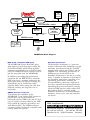
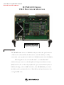
M OT OR OL A CO MP UT ER G RO UP
B o ar d L ev el P r o d u ct s
M V M E 230 0 SE R I E S
V M E P RO CE SSO R M O D UL E S
With compliments
Helmut Singer Elektronik
www.helmut-singer.de [email protected]
fon +49 241 155 315
fax +49 241 152 066
Feldchen 16-24 D-52070 Aachen Germany
A d va n t a g e s
T h e M V M E 2 3 0 0 s e r i e s o f V M E b o a r d s p r o v i d e s th e p e r f o r m a n c e
o f M o to r o l a ’ s P o w e r P l u s A r c h i te c t u r e , a n d t h e a b i l i ty t o fu l l y
c u s to m i z e y o u r a p p l i c a t i o n w i th t w o P CI M e z z a n i n e C a r d s ( P M Cs ).
U ti l i z i n g M o t o r o l a ’ s P o w e r P C 6 0 3 ™ o r P o w e r P C 6 0 4 ™
3 2 -b i t m i c r o p r o c e s s o r s , th e P e r i p h e r a l C o m p o n e n t I n t e r c o n n e c t
( P C I) b u s f o r t h e o n - b o a r d p e r i p h e r a l s , p r o c e s s o r / m e m o r y b u s to
P CI b u s b r i d g e , a n d a V M E i n t e r fa c e , th e M V M E 2 3 0 0 p r o c e s s o r
m o d u l e s p a c k o p ti m u m l e v e l s o f fl e x i b i l i t y a n d p e r f o r m a n c e i n to
a s in gl e V M E sl o t .
F e a t ur e s
T h e M o t o r o l a C om m i t m e n t
• PowerPC 603 or PowerPC 604
32 -bit microprocessor
Motorola Computer Group is committed to providing
• L1 cache—16KB/16KB PowerPC
603 or 32KB/32KB PowerPC 604
MVME2300 series reinforces this commitment by providing
• 16MB to 128MB of on-board ECC
DRAM
the tenets of open computing: modularity, scalability,
best-in-class embedded computing solutions. The
superior hardware, price performance, and faithfulness to
• Two 32-pin PLCC/CLCC sockets for
Flash memory; up to 1MB capacity
for on-board firmware or userspecified requirements
portability, and interoperability.
• 4MB on-board Flash memory for
user-specified requirements
commitment to quality and reliability of products to our
• On-board debug monitor with selftest diagnostics
• Two IEEE P1386.1 compliant
32/64-bit PMC expansion slots with
front panel and P2 I/O
• 64-bit PCI expansion mezzanine
connector
• 8K x 8 NVRAM and time-of-day
clock with replaceable battery
backup
• One asynchronous serial debug port
• Four 32-bit timers, one 16-bit
timer, one watchdog timer
• Ethernet transceiver interface with
32-bit PCI local bus DMA,
10/100Mb/s with auto-negotiate
speed select
• A32/D32/BLT64 VMEbus
master/slave interface with system
controller function; highperformance DMA supports
VMEbus D64 and 64-bit PCI local
bus memory burst cycles
• 4-level requester, 7-level interrupter,
and 7-level interrupt handler for
VMEbus
• One VME slot, even when fully
configured with two PMCs
The MVME2300 is offered with a five-year limited warranty
which reduces the cost of ownership and demonstrates our
OEM partners.
Motorola Computer Group is ISO9001 registered, and
provides world class quality in manufacturing, engineering,
sales, and marketing.
O r d e r i ng I nf o r m a t i o n
Part Number
Description
MVME2301
200 MHz MPC603, 16MB ECC DRAM, 5MB Flash
MVME2302
200 MHz MPC603, 32MB ECC DRAM, 5MB Flash
MVME2303
200 MHz MPC603, 64MB ECC DRAM, 5MB Flash
MVME2304
200 MHz MPC603, 128MB ECC DRAM, 5MB Flash
MVME2305
300 MHz MPC604, 16MB ECC DRAM, 5MB Flash
MVME2306
300 MHz MPC604, 32MB ECC DRAM, 5MB Flash
MVME2307
300 MHz MPC604, 64MB ECC DRAM, 5MB Flash
MVME2308
300 MHz MPC604, 128MB ECC DRAM, 5MB Flash
Note: MVME230 x-900 series available with original style VMEbus ejector
handles
Related Products
PMCSPAN-002
PMCSPAN(1)-002
PMCSPAN-010
PMCSPAN(1)-010
MPMCxxx
Documentation
V2300A/IH
V2300A/PG
PMCSPANA/IH
PPCBUGA1/UM
PPCBUGA2/UM
PPCDIAA/UM
Primary PCI expansion, mates directly to the
MVME2300 providing slots for either two singlewide or one double-wide IEEE P1386.1 compliant
PMC cards; optional PMCSPAN-010
PMCSPAN-002 with original style VMEbus ejector
handles
Secondary PCI expansion, plugs directly into
PMCSPAN-002 providing two additional PMC slots
PMCSAN-010 with original style VMEbus ejector
handles
Motorola’s family of PMC modules; ask your sales
representative for details
MVME2300 Installation and Use
Programmer’s Reference Guide
PMCSPAN Installation Guide
PPC1BUG User’s Manual, Part 1 of 2
PPC1BUG User’s Manual, Part 2 of 2
Firmware Diagnostics Manual
Flash
®
603 or 604
Memory
Controller
PCI Chipset
Bridge
64
RAM
1 MB
Two PLCCs
(Socketed)
PCI Expansion
- 16MB to 128MB
ECC DRAM
- 4MB Flash
16
PowerPC Bus—A32/D64
PCI Local Bus—A32/D64
64
DEC 21140
PMC
Slot 1
PCI to VME
Bridge
PMC
Slot 2
Tundra Universe
W83C553
10BaseT/100BaseTX
FP I/O
PMC FP I/O
ISA Bus—A16/D8
P1
SNAPHAT
Battery
PMC P2 I/O
64
64
Ethernet
PCI to ISA
Bridge
PMC P2 I/O
NVRAM
RTC
Async Serial
PMC FP I/O
P2
VME64 Extension Connectors
PC16550
MK48T59
EIA232
FP I/O
MVME2300 Block Diagram
IEEE P1386.1 Compliant PMC Slots
PowerPlus Architecture
The MVME2300 features dual PMC ports
with support for both front panel and P2 I/O.
P2 I/O–based PMCs which follow the PMC
committee recommendation for PCI I/O when
using the VME64 extension connector will be
pin-out compatible with the MVME2300.
The PowerPlus Architecture is a processor
and bus architecture fully optimized to get the
maximum performance from the PowerPC ®
microprocessor family, the PCI bus, and the
VMEbus. The outstanding performance of
VME processor boards based on the
PowerPlus Architecture is not due to a single
factor. A number of elements in the design of
the PowerPlus Architecture contribute to its
outstanding performance including the
Processor/Memory subsystem, high-speed
local bus, optimally decoupled architecture,
decoupling the processor from PCI, and the
advanced VME interface which reduces PCI
delays. More detail is available on the
PowerPlus Architecture in the MVME2600
datasheet. Contact your sales representative
for details.
In addition to providing high performance
expansion I/O, the IEEE P1386.1 compliant
PMC ports form a common architecture for
future generations of products. Changing I/O
requirements can be satisfied by simply
replacing PMCs while reusing the same base
platform, reducing the long-term cost of
ownership.
VME64 Extension Connector
To maximize the capabilities of the
MVME2300, 5-row 160-pin DIN connectors
replace the 3-row 96-pin connectors
historically used on VME for P1 and P2. Two
rows, Z and D, have been added to the VME
P1/J1 and P2/J2 connectors providing a user
with additional I/O. The VME64 extension
connector is 100% backward compatible with
existing VME card systems.
With compliments
Helmut Singer Elektronik
www.helmut-singer.de [email protected]
fon +49 241 155 315
fax +49 241 152 066
Feldchen 16-24 D-52070 Aachen Germany
S p e c i f i c a t i on s
IEEE P1386.1 PCI Mezzanine Card Slot
MVME2300 VME Processor Module
Address/Data:
Processor
Microprocessor:
Clock Frequency:
On-chip Cache (I/D):
SPECint95, measured:
SPECfp95, measured:
MPC603
200 MHz
16KB/16KB
not available
not available
MPC604
300 MHz
32KB/32KB
10.8
9.72
Memory
ECC Protected Main Memory:
Capacity (60ns EDO):
Capacity (50ns EDO):
Single Cycle Accesses:
Read Burst Mode (60ns):
Read Burst Mode (50ns):
Write Burst Mode:
Architecture:
Dynamic RAM with 66 MHz bus
16 or 32MB
64 or 128MB
9 Read/4 Write
9-1-2-1 idle; 3-1-2-1 aligned page hit
8-1-1-1 idle; 2-1-1-1 aligned page hit
4-1-1-1 idle; 3-1-1-1 aligned page hit
128-bit, 2 way interleaved
EEPROM/Flash:
Capacity:
Read Access (4MB port):
Read Access (1MB port):
On-board programmable
1MB via two 32-pin PLCC/CLCC sockets;
4MB surface mount
68 Clocks (32 byte burst)
260 Clocks (32 byte burst)
NVRAM:
Cell Storage Life:
Cell Capacity Life:
Removable Battery:
8KB; 4KB available for users
50 years at 55° C
10 years at 100% duty cycle
Yes
VMEbus ANSI/VITA 1-1994 VME64
DTB Master:
DTB Slave:
Arbiter:
Interrupt Handler/Generator:
System Controller:
Location Monitor:
(IEEE STD 1014)
A16-A32; D08-D64, BLT
A24-A32; D08-D64, BLT, UAT
RR/PRI
IRQ 1-7/Any one of seven IRQs
Yes, jumperable or auto detect
Two, LMA32
Ethernet Interface
Controller:
PCI Local bus DMA:
Connector:
DEC 21140
Yes
Routed to front panel via an RJ-45
A32/D32/D64, PMC PN1, PN2, PN3, PN4
connectors
PCI Bus Clock:
33 MHz
Signaling:
5V
Power:
+3.3V, +5V, ±12V, 7.5 watts maximum per
PMC slot
Module Types:
One double-wide or two single-wide front
panel I/O or P2 I/O
Note: P2 I/O from PMC slot 2 is only accessible to systems equipped for VME64
extension connectors
PCI Expansion Connector
Address/Data:
PCI Bus Clock:
Signaling:
Connector:
A32/D32/D64
33 MHz
5V
114-pin connector located on the planar of the
MVME2300
Power Requirements
+ 5V ± 5%
MVME2300 w/ MPC603 @ 200 MHz:
4.0 A typical, 4.75 A max.
MVME2300 w/ MPC604 @ 300 MHz:
4.5 A typical, 5.5 A max.
Note: Power requirements are PMC dependent at +12 and –12 volts.
Demonstrated MTBF
Mean/90% Confidence:
190,509 hours/ 107,681 hours
Board Size
Height:
Depth:
Front Panel Height:
Width:
Max. Component Height:
233.4 mm (9.2 in.)
160.0 mm (6.3 in.)
261.8 mm (10.3 in.)
19.8 mm (0.8 in.)
14.8 mm (0.58 in.)
Environmental
Temperature:
Altitude:
Humidity (NC):
Vibration:
Operating
0° C to +55° C,
forced air cooling
5,000 m
10% to 80%
2 Gs RMS,
20–2000 Hz Random
Nonoperating
–40° C to +85° C
15,000 m
10% to 90%
8 Gs RMS,
20–2000 Hz Random
Asynchronous Serial Port
Regulatory Compliance
Controller:
Connector:
Intended for use in systems meeting the following EMI/RFI regulations:
US:
FCC Class B
Canada:
DOC Class B
Europe:
VDE Class B, CISPR-B, CE Mark
Safety:
All printed wiring boards (PWBs) are manufactured with a
flammability rating of 94V-0 by UL recognized manufacturers.
PC16550
Routed to the front panel via an RJ-45
Counters/Timers
TOD Clock Device:
Real-Time Timers/Counters:
Watchdog Timer:
M48T59; 8KB NVRAM
Four 16-bit programmable
Time-out generates reset
Miscellaneous
Front panel:
Reset and Abort switches; four LEDs for Fail,
CPU, PMC1, PMC2
Software Support
The MVME2300 is supported by a variety of operating
systems, including a complete range of real-time
operating systems and kernels.
For more information, visit our World Wide Web site at http://www.mot.com/computer/
For fax-back service dial 1-800-682-6128 in the U.S. and 602-438-4636 outside of the U.S.
To call us dial 1-800-759-1107 in the U.S. and 512-434-1526 outside of the U.S.
Corporate headquarters address: Motorola Computer Group, 2900 S. Diablo Way, Tempe, AZ 85282
Copyright 1997 Motorola, Inc.
Data Sheet: M2300-D3
Computer Group
Motorola and the Motorola logo are registered trademarks of Motorola, Inc. PowerPC and the PowerPC logo are registered trademarks; and PowerPC 603 and PowerPC 604 are trademarks of
International Business Machines Corporation and are used by Motorola, Inc. under license from International Business Machines Corporation. All other names, products, and /or services mentioned
may be trademarks or registered trademarks of their respective holders.
This data sheet identifies products, their specifications, and their characteristics, which may be suitable for certain applications. It does not constitute an offer to sell or a commitment of present or
future availability, and should not be relied upon to state the terms and conditions, including warranties and disclaimers thereof, on which Motorola may sell products. A prospective buyer should
exercise its own independent judgement to confirm the suitability of the products for particular applications. Motorola reserves the right to make changes, without notice, to any products or
information herein which will, in its sole discretion, improve reliability, function, or design. Motorola does not assume any liability arising out of the application or use of any product or circuit
described herein; neither does it convey any license under its patent or other intellectual property rights or under others. This disclaimer extends to any prospective buyer, and it includes Motorola’s
licensee, licensee’s transferees, and licensee’s customers and users. Availability of some of the products and services described herein may be restricted in some locations.