1
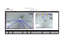
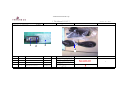
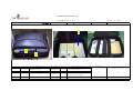
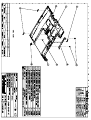
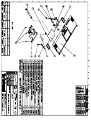
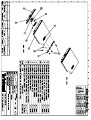
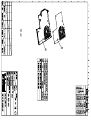
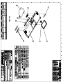
Table of Contents
efio!121A BOM……………………………………………………………….
1
efio!121A Sub. Assembly S.O.P…………………………….………………...
9
efio!121A 12.1" LCD Instruction manual……………………………………..
24
efio!121A System Setup Instruction manual…………………………………..
34
efio!121A (Complete set) Instruction Manual………………………………...
55
efio!121A (CARRYING BAG) Packaging Instruction Manual……………….
67
efio!121A 2-IN-1 Packing S.O.P……………………………………………...
73
efio!121A Disassembly………………………………………………………..
82
efio!121A Notebook BOM
(Internal code: D212A)
========== ===============
LEVELS
ITEM NUMBER
123456789 M-D212A
========== ===============
PCBA
.....5
82-873030-00
....4
80-690000-00D
D212A-PCB ASS'Y-VI-K7-REV:0-W/WI
P22AJ-PCB ASS'Y-VI-USB-REV:D
SYSTEM CABINET
.....5
27-300051-20
.....5
27-330000-00
.....5
28-200022-11
.....5
29-001638-02
.....5
29-015340-00
.....5
40-002311-00
.....5
40-003510-11
.....5
41-721520-03
.....5
41-721526-05
.....5
41-850520-06
.....5
50-022150-70
.....5
50-023421-00
.....5
50-035141-30
.....5
50-035142-30
.....5
50-963001-20
.....5
50-963601-00
.....5
51-350094-01
.....5
51-350094-02
.....5
51-350094-03
.....5
51-350094-10
.....5
51-350094-15
.....5
51-350094-16
N222S1-GASKET TAPE-D4877A
ALL MODEL-THERMAL PAD FOR HEATSI
2nd FAN-L=80mm-W/SPONGE
N222S1-RJ11 JACK HARNESS-SH638B
P22AJ-SB-USB FPC-CA3400
N222S1-HARNESS COVER-C33210
P22AJ-HEATSINK MODULE W/FAN-SCRE
SCREW ISOT-M2X3L-SELF-LOCKING ¡í
SCREW ISOT-M2.6X5L H=0.8mm-NYLOK
SCREW ISOP-M2X6L-SELF-LOCKING-B3
P22AJ-RAM DOOR-#8028-C3323E
D212A-MYLAR FOR RAM DOOR-BLACK-I
D212A-HINGE COVER R-#8028-E4343D
D212A-HINGE COVER L-#8028-E4342E
P22AJ-CPU DOOR ASS'Y-#8028-E1081
D212A-UPPER COVER ASS'Y-#8028/85
CONDUCTIVE SPONGE 5X2X1000mm-KL1
CONDUCTIVE SPONGE 5X3.5X1000mm-K
CONDUCTIVE SPONGE 5X5.5X1000mm-K
CONDUCTIVE SPONGE 5X0.5X1000mm-K
P88S-CONDUCTIVE SPONGE 10X0.5X10
P93S-CONDUCTIOVE SPONGE 10X2X100
===============================================
DESCRIPTION
QTY
D212A ID2 MODEL
===============================================
1
1
1
1
1
1
1
1
1
4
2
17
1
1
1
1
1
1
0.03
0.08
0.08
0.085
0.215
0.03
efio!121A Notebook BOM
(Internal code: D212A)
========== ===============
LEVELS
ITEM NUMBER
123456789 M-D212A
========== ===============
.....5
51-350100-00
.....5
52-000000-20
.....5
52-002020-00
.....5
52-002021-00
.....5
52-002022-20
.....5
52-002030-00
.....5
52-002080-00
===============================================
DESCRIPTION
QTY
D212A ID2 MODEL
===============================================
P88TEM-SPONGE 5X1X1000mm
0.02
P22AJ-RUBBER FOOT-PANTONE 428C-D
2
N222S1-HDD RUBBER-D46930
1
N222S1-SCREW RUBBER-D48290
2
P22AJ-LOWER CD-ROM RUBBER-PANTON
1
N222S8P-SUPPORT RUBBER-20X20X5.5
1
P22AJ-RUBBER FOR USB-4X2mm,T=2mm
1
LOWER COVER KIT
......6
40-002420-04
......6
40-006040-00
......6
40-011951-00
......6
41-420520-03
......6
41-690022-48
......6
50-023310-00
......6
50-023335-00
......6
50-043000-30
......6
51-036041-00
......6
51-036042-00
......6
52-000000-20
P22AU-LOWER COVER #8028M-B1277D
N222S1-BATTERY HOOK-B3377A
N222S1-BATTERY LATCH SPRING-D479
SCREW BPS/W (¡í5.5)-M2X3L-NYLOKWASHER-OD=4.8 IO=2.2 T=0.5-D4883
N222S8L-MYLAR-10X4X0.2T-E43290-S
P22AJ-MYLAR FOR RJ11 LEFT SIDE-t
P22AJ-BATTERY LATCH-#8028-D4540E
N222S1-HDD SPONGE FOR LOWER UP S
N222S1-HDD SPONGE FOR LOWER DOWN
P22AJ-RUBBER FOOT-PANTONE 428C-D
1
1
1
2
2
1
1
1
1
1
2
PALM REST KIT
......6
22-300036-00
......6
29-016338-00
......6
40-007060-00
......6
40-030530-02
......6
40-030696-00
SPK (R)(L) W/MICROPHONE-C33790-S
P22AJ-FFC (P=1.0) FOR TOUCHPAD-C
N222S1-CU-FOIL FOR SPEAKER BRACK
N222S8P-TOUCH PAD BRACKET-B2311C
N222S1-SPEAKER BRACKET-D46900
1
1
1
1
2
efio!121A Notebook BOM
(Internal code: D212A)
========== ===============
LEVELS
ITEM NUMBER
123456789 M-D212A
========== ===============
......6
41-721520-03
......6
50-023320-00
......6
50-023335-20
......6
50-040167-00
......6
50-963601-10
......6
50-963601-20
......6
51-350094-01
......6
73-080052-00
===============================================
DESCRIPTION
QTY
D212A ID2 MODEL
===============================================
SCREW ISOT-M2X3L-SELF-LOCKING ¡í
5
N222S8P-MYLAR 38X10X0.2T-E435301
P22AJ-MYLAR FOR SPEAKER BRACKET1
P78-MICRO PHONE RUBBER-B4549A
1
D212A-PALM REST ASS'Y #8028-W/O WLAN
1
D212A-PALM REST ASS'Y W/WLAN-#8027
1
CONDUCTIVE SPONGE 5X2X1000mm-KL1
0.02
TOUCH PAD-FOR SOTEC-SYNAPTICS-TM
1
UPPER COVER KIT-W/Z ANTENNA
......6
22-600060-11
PIFA ANTENNA-C3530A-P22T
......6
27-300021-00
A2121-DOUBLE ADHESIVE (R)-WX4mm
......6
50-963601-00
D212A-UPPER COVER ASS'Y-#8028/85
1
1
1
24X CDROM ASS'Y FOR TEAC
....4
50-963001-70
1
P22AJ-#8028 TEAC CD-ROM BEZEL AS
24X PANASONIC COMBO ASS'Y #8028
....4
50-963001-10
P22AJ-PANASONIC COMBO BEZEL ASS'
1
24X PANASONIC COMBO ASS'Y #8735
....4
50-963601-D0
D212A-PANASONIC COMBO BEZEL ASS'
1
8X DVD-ROM ASS'Y-FOR QSI
.....5
50-963401-40
1
HDD KIT
P22T-QUANTA DVD-ROM BEZEL ASS'Y-
efio!121A Notebook BOM
(Internal code: D212A)
========== ===============
LEVELS
ITEM NUMBER
123456789 M-D212A
========== ===============
...3
40-008140-00
...3
60-010001-00
....4
40-030691-00
....4
41-870130-04
===============================================
DESCRIPTION
QTY
D212A ID2 MODEL
===============================================
D212A-AL FOIL FOR HDD BRACKET-E4
2
PE BAG 70X120mm
1
N222S1-HDD BRACKET-C3421B
1
SCREW ISOF-M3X4L-B3519K
4
US KB
...3
71-700185-01
K/B-85 KEY-US-N222S8-JME
1
KR KB
...3
71-710104-00
K/B-85 KEY-KR-N222S8PII-NEW MICR
1
SWISS KB
...3
71-710106-00
K/B-85 KEY-SW-36599#-N222S8PII-N
1
GR KB
...3
71-710107-00
K/B-85 KEY-GR-GRAY-N222S8SA-JME-
1
FR KB
...3
71-710105-00
K/B-85 KEY-FR-N222S8SA-JME-FOR S
1
UK KB
...3
71-710108-00
K/B-85 KEY-UK-N222S8SA-JME-FOR S
1
TW KB
...3
71-710102-00
K/B-85 KEY-TW-N222S8SA-JME-FOR S
1
TL KB
efio!121A Notebook BOM
(Internal code: D212A)
========== ===============
LEVELS
ITEM NUMBER
123456789 M-D212A
========== ===============
...3
71-710128-00
===============================================
DESCRIPTION
QTY
D212A ID2 MODEL
===============================================
K/B-85 KEY-TL-N222S8L/P-JME-FOR
1
RU KB
...3
71-810124-00
K/B-85KEYS-RU-#36599-D212A-W/NEW
1
JP KB
...3
71-700185-17
K/B-85 KEY-JP-N222S8-JME
1
N222S1-HARNESS FOR HSD 12.1" LCD
P22AJ-AL FOIL FOR LCD COVER-B233
N222S8-LCD HOOK SPRING-D49610
N222S8P-DISPLAY HINGE-C3663A-SOT
N222S8P-LCD BRACKET R-C36600-SOT
N222S8P-LCD BRACKET L-C36610-SOT
SCREW BPS/W (¡í5.5)-M2X3L-NYLOKSCREW ISOT-M2.6X4L H=0.8mm-NYLOK
SCREW ISOT-M2.6X6L ¡íD4.5/H0.8mm
SCREW ISOT-M2X3L-SELF-LOCKING ¡í
SCREW ISOT-M2X6L-NI+NYLOK #1 I
N222S8L-RUBBER PAD-B4405N-SOTEC
N222S8L-RUBBER PAD-C4328D-SOTEC
N222S8P-MYLAR FOR LCD HARNESS-E4
D212A-MYLAR FOR LCD HOOK-BLACK-E
D212A-LCD COVER ID2-#8027-B12860
N222S8P-MICA FOR LCD COVER-C3665
D212A-LCD HOOK ASS'Y-#8801
1
1
1
2
1
1
2
2
2
6
2
1
1
1
1
1
1
1
DISPLAY ASS'Y
...3
29-001640-01
...3
40-008122-00
...3
40-011701-00
...3
40-015020-00
...3
40-030531-00
...3
40-030532-00
...3
41-420520-03
...3
41-720526-04
...3
41-721026-06
...3
41-721520-03
...3
41-721520-06
...3
50-020385-20
...3
50-021268-20
...3
50-023324-00
...3
50-023420-00
...3
50-033071-00
...3
50-212960-02
...3
50-963601-C0
efio!121A Notebook BOM
(Internal code: D212A)
========== ===============
LEVELS
ITEM NUMBER
123456789 M-D212A
========== ===============
...3
52-002350-10
...3
76-030105-00
===============================================
DESCRIPTION
QTY
D212A ID2 MODEL
===============================================
D212A-HOOK SUPPORT RUBBER-PANTON
1
INVERTER-5V-5W-10X123mm-FOR 12.1
1
5 IN 1 PACKING FOR US
...3
60-010026-00
...3
60-010200-00
...3
60-012001-00
...3
60-012002-00
...3
61-000845-00
...3
61-007051-00
...3
61-012184-00
...3
61-012193-00
...3
61-015060-00
...3
61-050083-10
...3
61-960601-A0
...3
61-960601-B0
...3
63-001132-00
PE BAG 200X150 mm A4382
BIG PE BAG
PE BAG W/ARTWORK 360*380
ANTI-STATIC BAG 110*290
PET OPC 1206 STRAC
N222S1-5IN1 PAPER CUSHION FOR BA
N222S1-5IN1 PAPER BOARD FOR BATT
N222S1-5 IN 1 PAPER TUBE-D48980
N222S1-PROTECT PAPER FOR K/B-D48
N222S1-5IN1 CARTON-A4873B
N222S1-5IN1 LOWER PAPER CUSHION
N222S1-5IN1 UPPER PAPER CUSHION
PACKING LABEL 100X150mm-C4219A
1
0.017
1
1
0
0.2
0.2
0.4
1
0.2
0.2
0.2
0.2
GENERIC 2 IN 1 PACKING
...3
29-130244-00
...3
60-010001-00
...3
60-010070-00
...3
62-030273-00
...3
70-140629-01
...3
76-010562-00
....4
50-020002-00
....4
60-005040-00
P93SE-MODEM CABLE-CA244
PE BAG 70X120mm
PLASTIC BAG-35cmX25cm-FOR CD/MAN
USER'S MANUAL-DE/EN-R:00-D212A
UTILITY CD-R1.01-D212A
ADAPTER-20V-60W-LSE9802A2060-SLS
PLASTIC HANDLE-A3280
R14SE-CARRY BAG FOR GENERIC
1
1
1
1
1
1
1
1
efio!121A Notebook BOM
(Internal code: D212A)
========== ===============
LEVELS
ITEM NUMBER
123456789 M-D212A
========== ===============
....4
60-010003-00
....4
60-010026-00
....4
60-010067-00
....4
60-010200-00
....4
61-007050-00
....4
61-012180-00
....4
61-012195-00
....4
61-015061-00
....4
61-040064-40
....4
61-050094-01
....4
61-960601-80
....4
61-960601-90
===============================================
DESCRIPTION
QTY
D212A ID2 MODEL
===============================================
PE BAG 220X280mm
1
PE BAG 200X150 mm A4382
1
PE-BAG-400X300mm-B4752A-P79S-PE
1
BIG PE BAG
0.041
N222S1-PAPER CUSHION-C34160-FOR
1
N222S1-PAPER TUBE-C3418A-FOR BAT
1
N222S1-PAPER SHEET-C34610-FOR MO
1
N222S1-PROTECT PAPER FOR SYSTEM1
A2010-COLOR BOX W/CARRY BAG-A245
1
P88TE-CARTON FOR W/CARRY BAG-A24
0.5
N222S1-2IN1 L PAPER CUSHION ASS'
1
N222S1-2IN1 R PAPER CUSHION ASS'
1
PARTS KIT FOR GERERIC-W/O LOGO
...3
50-023425-00
D212A PROTECTIVE MYLAR FOR LCD C
...3
50-034080-00
D212A-LCD PANEL W/O LOGO-#8126-B
...3
63-040100-Q0
D212A-FCC LABEL SYSTEM-C3435-FOR
1
1
1
PARTS KIT FOR T/H
...3
40-006120-00
...3
50-034080-10
...3
63-040102-R5
D212A-LCD FRONT PLATE ID2-FOR TW
D212A-LCD PANEL FOR TH-#8126-B12
D212A-MODEL NAME EFIO! 122A LABE
1
1
1
56K MODEM ASS'Y
...3
41-721520-03
...3
63-250190-00
...3
76-060007-00
SCREW ISOT-M2X3L-SELF-LOCKING ¡í
KEY PARTS BARCODE LABEL-KL18260
MDC MODEM CARD-SMART LINK-MDC56S
2
1
1
efio!121A Notebook BOM
(Internal code: D212A)
========== ===============
LEVELS
ITEM NUMBER
123456789 M-D212A
========== ===============
===============================================
DESCRIPTION
QTY
D212A ID2 MODEL
===============================================
POWER CORD FOR JP (2-PIN)
..2
29-020151-10
P10-POWER CORD-JP 2P-BLACK-SP-12
POWER CORD FOR US, TW, Phillippine, Korea, Canada
..2
29-020181-10
N222S1-POWER CORD FOR US/PL/C-SP
1
1
POWER CORD FOR German, French, Holland, Austrian, Swedish, Norwegian, Belgium
..2
29-020183-11
ALL MODEL-POWER CORD FOR GR/FR/H
1
POWER CORD FOR KR
..2
29-020183-20
ALL MODEL-POWER CORD FOR KR-SP-0
1
POWER CORD FOR England, Singapore, Hong Kong
..2
29-020185-20
9000,5000,2000,1000,N222S1-POWER
1
POWER CORD FOR ML
..2
29-020186-10
N222S1,N222S8-POWER CORD FOR CHI
1
WIRELESS
...3
...3
P22T-RUBBER FOR WIRELESS-E45500
WLAN MODULE MINI USB W/HARNESS-T
2
1
52-003091-00
76-070005-00
Tw inhead International Corp.
DOCUMENT CODE:TESOP261
efio!121A Sub Ass'y S.O.P.
REVISION:
0
RELEASE DATE:
DESCRIPTION
NEW RELEASE
PAGE: 14 (total 14 pages)
CONCURRED
PREPARED BY
APPROVED BY
BY
PE:
NA
Twinhead International Corp.
(Document NO.):TESOP261
Page/Version
Name of S.O.P: efio!121A SUB ASSEMBLY SOP
REV: 0
Page
Version
1. Instruction manual
2.Fabricated material setup instruction (19 people
required)
P.01
1
0
P.2~P.14
2
0
3
0
1.6501 Upper Cover Assembly (2 people)
P.02~P.03
4
0
2.6502 LOWER COVER Assembly (3 people)
P.04 ~ P.06
5
0
3.6504 CD-ROM Assembly
P.07~ P.08
6
0
4.6506 HDD Assembly (1 people)
P.09
7
0
5.6551 PalM REST Assembly (5 people)
P.10~ P.14
8
0
9
0
10
0
11
0
12
0
13
0
14
0
(2 people)
BOM calls for real fabric; the numbers in the S.O.P are for reference only
This manual is for efio!121A model System setup
PAGE:01
Page
Version Page
Version
Page
Version
Tw inhead International Corp.
( Twinhead S.O.P )
Name of S.O.P: efio!121A UPPER COVER SOP
Working name: 6501-1
Revision:
( Document NO): TESOP261
0
Date: 2003.09.01
(Manufacturing Section): PE
Explanation of illustration
1
13mm
35mm
2
8mm
3
5
27mm
When attaching this sponge,
align with red lines
Difference
Operating Item
Part name/specification
Part/number
Q'TY
Operation description
Important note
Jig/fixture
Check the appearance
NA
1
efio!121A-UPPER COVER ASS'Y
50-963601-00
1
Check UPPER COVER to make sure it is
not damaged or distorted; clean with
alcohol
2
CONDUCTIVE
SPONGE(10X0.5X45mm)
51-350094-15
2
Attach two conductive sponges as shown
in diagram
Do not allow sponge to cross red
line
NA
3
CONDUCTIVE
SPONGE(10X0.5X45mm)
51-350094-15
1
Attach two conductive sponges as shown
in diagram
Do not allow sponge to cross red
line
NA
4
CONDUCTIVE
SPONGE(10X0.5X35mm)
51-350094-15
1
Attach two conductive sponges as shown
in diagram
NA
NA
5
CONDUCTIVE
SPONGE(10X2X20mm)
51-350094-16
1
Attach two conductive sponges as shown
in diagram
NA
NA
PAGE:
02
Tw inhead International Corp.
( Twinhead S.O.P )
Name of S.O.P: efio!121A upper cover SOP
( Document NO): TESOP261
Revision: 0
Working name: 6501-2
Date: 2003.09.01
(Manufacturing Section): PE
Explanation of illustration
3
4
1
DOUBLE
ADHESIVE 25 mm
2
Difference
Implement
these steps
while wireless
lan function on
Operating Item
Part name/specification
Part/number
Q'TY
Operation description
Important note
Jig/fixture
1
DOUBLE
ADHESIVE(R)(25X4X0.15mm)
27-300021-00
1
Attach DOUBLE ADHESIVE on upper cover part; do Do allow tape to extend over
not allow tape to extend over edge
edge
NA
2
PIFA ANTENNA-C3530A-P22T
H
1
Place antenna on upper cover as shown in diagram;
make sure antenna and upper cover are tightly
connected
N/A
NA
3
TAPE (NARROW)(5~6cm)
61-080022-00
1
Use black tape to fix the antenna as shown in diagram
N/A
N/A
4
403 quick-drying glue
NA
1
Glue antenna magnet hook to upper cover's fillister
N/A
NA
PAGE: 03
Tw inhead International Corp.
( Twinhead S.O.P )
Working name: 6502-1
Name of S.O.P: efio!121A lower cover SOP
( Document NO): TESOP261
Revision: 0
Date: 2003.09.01
Explanation of illustration
(Manufacturing Section): PE
5
4
2
1
Difference
Operating Item
1
3
Part name/specification
Part/number
Q'TY
P22AU-LOWER COVER
40-002420-04
1
Check appearance for scratches or damage.
Operation description
Important note
NA
Jig/fixture
NA
2
N222S1-BATTERY LATCH
SPRING
40-011951-00
1
3
N222S1-BATTERY HOOK
40-006040-00
1
Hook the spring from the rear and assemble onto base.
Installing outer side of spring hook onto base first as
shown in diagram.
4
WASHER-OD=4.8 IO=2.2 T=0.5D48830
41-690022-48
2
Put screw WASHER on base and align with lockhole
NA
NA
5
SCREW BPS/W-M2X3L-NYLOK
41-420520-03
2
Tighten on hook in a.b. order
NA
Electrical screwdriver/Torque: 1.5±
0.5Kgf-cm
PAGE: 04
Note the direction of the spring
NA
NA
Tw inhead International Corp.
( Twinhead S.O.P )
Name of S.O.P: efio!121A lower cover SOP
Working name: 6502-2
Revision: 0
( Document NO): TESOP261
Date: 2003.09.01
(Manufacturing Section): PE
Explanation of illustration
1
5
38mm
3
4
6
Follow the edge of the line to
attach the Mylar. Be careful
to stick in the exact position
indicated.
2
Difference
Operating Item
Part name/specification
Part/number
Q'TY
1
N222S1-HDD SPONGE FOR LOWER
UP SIDE
Important note
Jig/fixture
51-036041-00
1
Attach as shown in diagram
N/A
Mylar
2
N222S1-HDD SPONGE FOR LOWER
DOWN SIDE
51-036042-00
1
Attach as shown in diagram
NA
NA
3
CONDUCTIVE SPONGE (5x3.5x80mm)
51-350094-02
1
Attach as shown in diagram (50mm)
NA
NA
4
CONDUCTIVE SPONGE (5x5.5x80mm)
51-350094-03
1
Attach as shown in diagram (50mm)
NA
NA
5
N222S8L-MYLAR-10X4X0.2T-SOTEC
50-023310-00
1
Attach black MYLAR on bottom cover as shown in
diagram
NA
6
P22AJ-MYLAR FOR RJ11 LEFT SIDE
t:0.2 (7X2X0.2tmm)
1
At RJ11, add Mylar on bottom cover as shown in
diagram
NA
50-023335-00
Operation description
PAGE: 05
NA
NA
Tw inhead International Corp.
( Twinhead S.O.P )
Working name: 6502-3
Name of S.O.P: efio!121A lower cover SOP
( Document NO): TESOP261
Revision: 0
Date: 2003.09.01
(Manufacturing Section): PE
Explanation of illustration
Must move
smoothly
1
Attach tightly
2
Difference
Operating Item
Part name/specification
Part/number
Q'TY
Attach tightly
Operation description
Important note
Jig/fixture
Note the direction: arrow
points right
NA
1
P22AJ-BATTERY LATCH
50-043000-30
1
Install BATTERY LATCH
2
P22AJ-RUBBER FOOT
52-000000-20
2
Attach rubber foot
N/A
NA
3
NA
NA
1
Place bottom cover in a protective bag
NA
NA
PAGE: 06
Tw inhead International Corp.
( Twinhead S.O.P )
Name of S.O.P: efio!121A CD-ROM SOP
Working name: 6504-1
( Document NO): TESOP261
Revision: 0
Date: 2003.09.01
(Manufacturing Section): PE
Explanation of illustration
3
1
b
Operating Item
Part name/specification
Part/number
CD-ROM 24X 224E -TECA
70-130124-00
DVD-ROM
70-200030-00
QSI SBW-242 COMBO
70-210016-00
2
N222S1-CD-ROM BRACKET
40-030692-01
3
SCREW ISOT-M2X3LSELF-LOCKING
1
4
a
c
3
2
Difference
Fixture
keyparts label
Q'TY
Operation description
Important note
Jig/fixture
Do not vibrate the CD-ROM
when carrying.
NA
1
Take a CD-ROM and check it's appearance
1
Install BRACKET on CD-ROM
NA
U type jag
41-721520-03
3
Lock up screws on BRACKET in a.b.c. order as
shown in diagram.
NA
Electrical screw driver/Torque:
1.5± 0.5Kgf-cm
63-250190-00
1
Attach keyparts label as shown in diagram.
NA
NA
PAGE: 07
Tw inhead International Corp.
( Twinhead S.O.P )
Name of S.O.P: efio!121A CD-ROM SOP
Working name: 6504-2
Revision: 0
( Document NO): TESOP261
Date: 2003.09.01
(Manufacturing Section): PE
Explanation of illustration
b
4
3
2
Poke from here
1
a
Difference
Operating Item
Part name/specification
1
NA
CD-ROM BEZEL
2
Part/number
NA
Q'TY
NA
Operation description
Take CD-ROM and eject disc tray
Important note
Jig/fixture
1
Install BEZEL on CD-ROM tray base.
Check that bezel serial number is
correct; Bezel must conform with
CD-ROM. Do not let BEZEL change
shape
NA
Eject tray 30 mm; place it on a table Screwdriver /Torque: 0.8±0.2Kgfsurface
cm
50-962801-XX
DVD BEZEL
50-963401-xx
CD-RW BEZEL
50-962801-XX
3
SCREW BTB 1.7*3L BLACK
41-650217-03
1
Lock up screws on BEZEL as shown in diagram.
CD-RW
4
SCREW BTB 1.7*3L BLACK
41-650217-03
2
Tighten screws in order of a.b. (When screwing CDRW's bezel , at (3)、(4) total of 3 screws.
NA
Electrical screwdriver/Torque:
0.8± 0.2Kgf-cm
Quanta DVD
5
TAPE (NARROW)-1cm
61-080022-00
1
When using Quanta DVD-ROM, attach a tape at the
BEZEL right side hook and then assemble.
Tape is required when using a
Quanta DVD
N/A
PAGE: 08
Tw inhead International Corp.
( Twinhead S.O.P )
Working name:6506-1
Name of S.O.P: efio!121A HDD SOP
( Document NO): TESOP261
Revision: 0
Date: 2003.09.01
Explanation of illustration
Work no.
2
3
1
a
(Manufacturing Section): PE
c
5
4
4
b
d
HDI
Port
7
Difference
Operating Item
1
8
Part name/specification
Part/number
HITACHI 20GB HDD
70-722201-00
HDD-30GB-IBM
70-822300-60
Q'TY
Operation description
1
Check HDD; make sure there are no scratches or damage.
Check the metal pins to make sure it is not banded.
Important note
Jig/fixture
Select drive based on customer's
needs.
NA
NA
HDD-40GB-FUJITSU
70-922400-40
2
KEY PARTS LABEL
63-250190-00
1
Attach as shown in diagram.
NA
3
N222S1-HDD BRACKET
40-030691-00
1
Install as shown in diagram
NA
NA
NA
Electrical screwdriver/Torque:
1.5 ±0.5Kgf-cm
NA
NA
According to BOM
HDD COPY machine
4
SCREW ISOF-M3.0 X 4.0L
41-870130-04
4
Tighten HDD BRACKET in a.b.c.d. order as shown in
diagram.
5
D212A-AL FOIL FOR HDD BRACKET
40-008140-00
2
Attach aluminum foil as shown in diagram
6
HDD IMAGE
65-000110-00
1
Copy HDI
7
MO LABEL
63-000710-00
1
Attach as shown in diagram when HDD COPY is finished.
Attach HDD LABEL as shown in diagram
N/A
NA
8
KAPTON TAPE(10mm)
27-319020-00
1
Attach yellow tape to HDD Bracket as shown in diagram.
Note: Tape should cover rack's
lockhole
NA
PAGE: 09
Tw inhead International Corp.
( Twinhead S.O.P )
Name of S.O.P: efio!121A PARM REST SOP
Working name: 6551-1
( Document NO): TESOP261
Revision: 0
Date: 2003.09.01
(Manufacturing Section): PE
Explanation of illustration
Use jig to clean
jagged edges.
1
3
2
Note gaps between
palm rest and
touchpad.
Difference
Operating Item
Part name/specification
D212A-PALM REST ASS'Y
Have wireless
use this palm
rest
Part/number
Q'TY
50-963601-10
1
Operation description
Check appearance; make sure there are no
scratches and no finger prints on touchpad
1
Important note
Jig/fixture
The windows must not push
out the palm rest's surfaces.
NA
NA
NA
D212A-PALM REST ASS'Y W/WLAN#8028
50-963601-20
1
2
TOUCH PAD-FOR SOTEC-SYNAPTICS
73-080052-00
1
Position TOUCH PAD on palm rest as shown in
diagram.
3
CONDUCTIVE SPONGE(5X2X20mm)
51-350094-01
1
Attach conductive sponge to TOUCH PAD matel Attach it along the edge of the
part as shown in diagram.
metal
PAGE: 10
NA
Tw inhead International Corp.
( Twinhead S.O.P )
Name of S.O.P: efio!121A PARM REST SOP
Working name: 6551-2
Revision: 0
( Document NO): TESOP261
Date: 2003.09.01
(Manufacturing Section): PE
Explanation of illustration
3
2
a
Difference
Operating Item
Note: Wires must
not be covered by
metal slice
Part name/specification
b
1
Part/number
Note: Wires must not be
covered by metal slice
Q'TY
Operation description
Important note
Jig/fixture
Shorter wire is for R side;
longer wire is for L side
NA
1
SPEAKER (R)(L)-W/O MICROPHONE
22-300036-00
1
Install SPEAKER on PALM REST as shown
in diagram.
2
N222S1-SPEAKER BRACKET
40-030696-00
2
Install speaker bracket to support speaker.
NA
NA
3
SCREW ISOT M2.0 X 3.0L
41-721520-03
2
Lock speaker up on speaker bracket in a
order of a.b as shown in diagram
NA
Electrical screwdriver/Torque:
1.5 ± 0.5Kgf-cm
PAGE: 11
Tw inhead International Corp.
( Twinhead S.O.P )
Name of S.O.P: efio!121A PARM REST SOP
Revision: 0
Working name: 6551-3
( Document NO): TESOP261
Date: 2003.09.01
(Manufacturing Section): PE
Explanation of illustration
Make the wires
tighten and stick it
2
4
1
3
wires above
metal slice
arrange wires in
fillister
arrange wires in
fillister
wires above
metal slice
wires inside
hook
Difference
Operating Item
Part name/specification
1
rubber for microphone
Part/number
50-040617-00
Q'TY
1
NA
1
Arrange SPEAKER wires
Attach tape to wires to fix as shown in diagram.
2
NA
3
TAPE (NARROW)-1cm
61-080022-00
1
4
N222S1 CU-FOIL FOR SPEAKER
BRACKET
40-007060-00
1
Operation description
Install rubber on microphone and install it at palm rest
Attach copper foil to right side of PALM REST as
shown in diagram
PAGE: 12
Important note
NA
Jig/fixture
NA
Arrange wires in position pillar
NA
NA
NA
NA
NA
Tw inhead International Corp.
( Twinhead S.O.P )
Name of S.O.P: efio!121A PARM REST SOP
Working name: 6551-4
( Document NO): TESOP261
Revision: 0
Date: 2003.09.01
(Manufacturing Section): PE
Explanation of illustration
Tape must be
attached at wire'ss
connection point.
1
4
3
2
Difference
Operating Item
Part name/specification
Part/number
Q'TY
Operation description
Important note
Jig/fixture
1
N222S8P-TOUCH PAD
BRACKET
40-030530-02
1
Check the metal slice make to sure its shape unchanged;
use jig set at a 30 degree angle.
NA
Adjust jig
2
N222S8P-MYLAR 38X10X0.2T
50-023320-00
1
Attach MYLAR to BRACKET as shown in diagram
NA
NA
3
SCREW ISOT M2X3L-NYLOK
41-721520-03
3
Lock screw on BRACKET in a order of a.b.c as shown
in diagram.
NA
Electrical screwdriver/Torque:
1.5 ± 0.5Kgf-cm
4
P22AJ-FFC (P=1.0) FOR
TOUCHPAD
29-016338-00
1
Insert TOUCH PAD wires as shown in diagram.
Do not cover banded wires.
NA
PAGE: 13
Tw inhead International Corp.
( Twinhead S.O.P )
Name of S.O.P: efio!121A PARM REST SOP
Working name: 6551-5
( Document NO): TESOP261
Revision: 0
Date: 2003.09.01
(Manufacturing Section): PE
Explanation of illustration
3
1
Difference
Operating Item
Part name/specification
2
Part/number
Q'TY
Operation description
Attach 6 cm long tape to fix Touchpad's wires as
shown in diagram.
Important note
Wires must be attached at
fixed point.
Jig/fixture
1
TAPE (NARROW)-2cm
61-080023-00
1
2
Tape(3cm)
61-080023-00
2
After arranging wires, attach 2-3cm long tape to fix
the wires as shown in diagram.
Make sure wires do not cover
lockhole's iron slice tape. Do
not attach on keypad hole
NA
3
P22AJ_MYLAR FOR SPEAKER
BRACKET (41X6.5X0.1mmt)
50-023335-20
1
Attach a Mylar at right side of speaker iron slice as
shown in diagram.
After attaching Mylar, the
iron slice is not visible
NA
4
NA
NA
1
Recheck to make sure palm rest is done and place in
PE bag
NA
NA
PAGE: 14
NA
Tw inhead International Corp.
DOCUMENT CODE:TESOP259
efio!121A 12.1" LCD Instruction manual
REVISION
2
RELEASE DATE:
PAGE: 9 (total 10 page)
DESCRIPTION
1. NEW RELEASE
PREPARED BY
PE:
CONCURRED BY
NA
APPROVED BY
Twinhead International Corp.
(Document NO.): TESOP259
REV:2
Page/Version:
efio!121A 12.1" LCD S.O.P. Contents
Page
Version
1.Instruction manual
P.01
1
2
2.Fabricated material setup instructions
P.02~P.09
2
1
3
0
4
1
1. (Refer to D/C NO:KE3-0113)
5
0
2. (Refer to D/C NO:KE3-0010)
6
0
3.KE3-0058
7
0
8
0
9
1
(Manpower:9 people include testing )
3. References:
4.Tool-Screwdriver, scotch tape
BOM calls for real fabric; the numbers in the S.O.P are for reference only
This manual is for efio!121A 12.1" LCD packaging instr
PAGE:01
Page
Version
Page
Version Page
Version
Twinhead International Corp.
( Twinhead S.O.P )
Working name: 6512-1
Name of SOP: efio!121A LCD MODULE ASS'Y SOP
Revision: 1
Date: 2003.09.25
4
1
2
5
Operating Item
(Manufacturing Section): PE
Examine the
switch, make sure
it works perfectly
3
Difference
(Document NO):TESOP259
Part name/specification
6
Part/number
D212A-LCD COVER-ID1-#8028
50-033070-01
D212A-LCD COVER ID2-#8027-B1286
50-033071-00
1
Q'TY
1
Operation description
Check appearance; make sure cover is not
scratched
Important note
Jig/fixture
NA
NA
Note the direction of the
spring when fitting in
NA
2
D212A-LCD HOOK ASS'Y
50-963601-C0/
50-963601-B0
1
3
D212A-MYLAR FOR LCD HOOK BLACK
50-023420-00
1
4
N222S8-LCD HOOK SPRING
40-011701-00
1
5
SCREW BPS/W M2.0 X 3.0L-NYLOK
41-420520-03
2
Firmly attach LCD hook to LCD cover as shown Check to make sure the hook
in the diagram
is working perfectly
6
N222S8P-MICA FOR LCD COVER
50-212960-02
1
Attach mica sheet to LCD COVER
Attach Mylar to LCD hook, then fit spring on
the LCD cover
PAGE: 02
NA
Electrical screwdriver/torque:1.5±0.5Kgfcm
NA
Twinhead International Corp.
( Twinhead S.O.P )
Name of SOP: efio!121A LCD MODULE ASS'Y SOP
(Document NO) :TESOP259
Revision: 1
Working name: 6512-2
Date: 2003.09.25
(Manufacturing Section): PE
Explanation of illustration
1
3
2
4
Level at the screw
hole, insert the
aluminum foil
between hinge and
iron
Level at the screw
hole, insert the
aluminum foil
between hinge and
iron
5
Difference
Operating Item
Part name/specification
Part/number
Q'TY
Operation description
Assemble LCD bracket on base as shown in the
diagram
Important note
Jig/fixture
NA
NA
1
N222S8P-LCD BRACKET L
40-030532-00
1
2
N222S8P-LCD BRACKET R
40-030531-00
1
3
P22AJ-AL FOIL FOR LCD COVER
40-008122-00
1
4
N222S8P-DISPLAY HINGE -SOTEC
40-015020-00
2
Assemble LCD HINGE on base as shown in the d
NA
NA
5
SCREW ISOT M2.6X4L
41-720526-04
2
Screw up left and right hinge LCD as shown in
the diagram.
NA
Electrical screwdriver/Torque:
2.0±0.5Kgf-cm
Assemble LCD bracket on base as shown in the
NA
diagram
Remove adhesive paper, attach aluminum foil to
Make sure it adheres smoothly
LCD COVER
PAGE: 03
NA
NA
Twinhead International Corp.
( Twinhead S.O.P )
Name of SOP: efio!121A LCD MODULE ASS'Y SOP
Align to
upper side
Explanation of illustration
4
8
5
6
Operating Item
1
Paste
TOSHIBA
LCD
(Manufacturing Section): PE
Align to
right side
1
Paste
Hyundai LCD
Date: 2003.09.15
7
3
2
Difference
(Document NO) :TE
Revision: 1
Working name: 6512-4
2
6cm
Part name/specification
LCD-12.1" XGA TFT-TOSHIBALTD121LAOS-11
Part/number
Q'TY
Operation description
72-11223G-00
1
Check LCD panel to make sure surface is not
scratched
63-250190-00
2
Attach key parts label
Important note
Jig/fixture
NA
NA
NA
NA
NA
NA
LCD wire material must rest
completely on the Mylar
NA
NA
NA
Wire must be places at least 7
cm from the edge
NA
2
KEY PARTS BARCODE LABEL
3
N222S1-HARNESS FOR HSD 12.1" LCD SH640C
29-001640-00
1
4
N222S8P-MYLAR FOR LCD HARNESS
50-023324-00
1
5
KAPTON TAPE
27-319003-00
1
Attach between golden adhesive tape and LCD
CONNECTOR as shown in the diagram
6
TAPE (6cm)
61-080007-01
1
Stick TAPE to fix LCD wire material
N222S8P-MYLAR_T FOR HYUNDAI LCD
50-023326-00
1
Tear off next Mylar; attach it aligned with upper
side as shown in the diagram
NA
NA
N222S8P-MYLAR_R FOR HYUNDAI LCD
50-023327-00
1
Tear off next Mylar; attach it aligned with right side
as shown in the diagram
NA
NA
CONDUCTIVE SPONGE(10x0.5x40mm)
51-350094-15
1
Sponge must be aligned with
the black line
NA
Assemble LCD HARNESS on LCD CONN as
shown in the diagram
Place white Mylar on LCD wire material and LCD
system
7
8
Attach conductive sponge to LCD wire material as
shown in the diagram
PAGE: 04
Twinhead International Corp.
( Twinhead S.O.P )
Name of SOP: efio!121A LCD MODULE ASS'Y SOP
Revision: 0
Working name: 6512-5
(Document NO): TESOP259
Date: 2003.09.01
(Manufacturing Section): PE
Explanation of illustration
1
2
5
3
Difference
4
Operating Item
Part name/specification
1
SCREW ISOT-M2X3L-LOCKING
2
NA
3
INVERTER-5V-5W-FOR 12.1LCD
4
DATE CODE LABEL
5
NA
Part/number
Q'TY
Operation description
Important note
Jig/fixture
NA
Electrical screwdriver/Torque:
1.5±0.5Kgf-cm
41-721520-03
2
Insert into LCD left and right racks as diagram
shows.
NA
1
Combine LCD and LCD COVER
NA
NA
76-030105-00
1
Get INVERTER and attach date code label
NA
NA
Connect INVERTER to LCD wire material and
LCD panel
NA
NA
63-000041-XX
NA
1
0
PAGE: 05
Twinhead International Corp.
( Twinhead S.O.P )
Name of SOP: efio!121A LCD MODULE ASS'Y SOP
(Document NO): TESOP25
Revision: 0
Working name: 6512-6
Date: 2003.09.01
Explanation of illustration
(Manufacturing Section): PE
LCD right side
INVERTER snap close to
bottom and stick it
3
INVERTER fixed as
diagram shows:
1
Scotch tape
fixed inverter
as diagram
shows
LCD left side
2
Difference
Operating Item
Part name/specification
1
NA
2
TAPE
3
SCREW ISOT M2X3L
Part/number
Q'TY
NA
0
27-319003-00
41-721520-03
1
4
Operation description
Attach INVERTER to the base
Attach 6cm golden tape onto the inverter as
shown in the diagram
Insert and tighten screws to the left and right
sides of the LCD as shown in the diagram
PAGE: 06
Important note
Jig/fixture
NA
NA
Golden tape must cover the
inverter
tape stand
NA
Electrical screwdriver/Torque:
1.5±0.5Kgf-cm
Twinhead International Corp.
( Twinhead S.O.P )
Name of SOP: efio!121A LCD MODULE ASS'Y SOP
Revision: 0
Working name: 6512-4
(Document NO): TESOP259
Date: 2003.09.01
(Manufacturing Section): PE
Explanation of illustration
3
1
Difference
4
2
Operating Item
Part/number
Q'TY
1
D212A-LCD PANEL#8126 FOR TH
Part name/specification
50-034080-10
1
2
D212A-HOOK SUPPORT RUBBER-BLACKE4677
52-002350-00
1
3
double adhesive
NA
2
4
double adhesive
NA
2
5
NA
NA
NA
Operation description
Check LCD panel to make sure surface is not
scratched
5
Important note
NA
Rubber hole's position and
panel hole's position must
Attach support rubber to LCD panel
align
Do not extend tape over the
Attach twin adhesive to LCD panel as shown in the d
panel's edge
Attach twin adhesive to LCD panel as shown in the d
Remove twin adhesive's other protective coat
PAGE: 07
Jig/fixture
NA
NA
NA
Do not extend tape over the
panel's edge
NA
NA
NA
Twinhead International Corp.
( Twinhead S.O.P )
Name of SOP: efio!121A LCD MODULE ASS'Y SOP
Explanation of illustration
(Document NO): TESOP259
Revision: 0
Working name: 6512-8
Date: 2003.09.01
(Manufacturing Section): PE
2
1
Do not clip line
here
3
Difference
Operating Item
Part name/specification
Part/number
Q'TY
NA
NA
Operation description
Important note
Jig/fixture
Embed the panel and LCD
NA
NA
1
NA
2
SCREW ISOT-M2X6L
41-721520-06
2
Tighten LCD PANEL as shown in the diagram
NA
Electrical screwdriver/Torque: 1.5±
0.5Kgf-cm
3
SCREW ISOT-M2.6X6L
41-721026-06
2
Tighten LCD PANEL as shown in the diagram
NA
Electrical screwdriver/Torque: 2.0±
0.5Kgf-cm
PAGE: 08
Twinhead International Corp.
( Twinhead S.O.P )
Name of SOP: efio!121A LCD MODULE ASS'Y SOP
Revision: 1
Working name: 6512-11
(Document NO): TESOP259
Date: 2003.09.25
(Manufacturing Section): PE
Explanation of illustration
1
2
3
Difference
Operating Item
Part name/specification
Part/number
Q'TY
NA
1
Operation description
Check appearance and make sure there are
no scratches. Tear a protective cover stick
behind the panel
Important note
Jig /fixture
NA
NA
1
NA
2
N222S8L-RUBBER PAD
50-020385-20
2
Attach rubber pad as shown in the
diagram
NA
NA
3
N222S8L-RUBBER PAD
50-021268-20
2
Attach rubber pad as shown in the
diagram
NA
NA
4
NA
NA
1
Place finished LCD panel into protective
bag
NA
NA
PAGE: 09
Twinhead International Corp.
DOCUMENT CODE:TESOP260
efio!121A System setup instruction manual
REVISION:
3
RELEASE DATE:
DESCRIPTION
1. UPDATE RELEASE
PAGE: 21 (total 21 page)
CONCURRED
PREPARED BY
APPROVED BY
BY
NA
Twinhead International Corp.
(Document NO.): TESOP260
efio!121A Contents of System Ass'y S.O.P.
Page/Version
1.Instruction manual
P.01
2.Fabricated material setup instruction (19 people required)
P.02~P.20
REV: 3
Page
Version
Page
Version
1
3
19
0
2
0
20
0
3
0
1. (D/C NO: KE3-0113)
4
1
2. (D/C NO: KE3-0010)
5
0
3. KE3-0058
6
1
7
1
8
1
9
0
10
0
10-1
0
11
0
12
1
13
1
14
0
15
1
16
2
BOM calls for real fabric; the numbers in the S.O.P are for reference only
17
0
This manual is for efio!121A model System setup
18
0
3. References:
4.Tool: Electrical screwdriver.tape.clip
PAGE:01
Page
Version
Page
Version
Twinhead International Corp.
( Twinhead S.O.P )
Working name: 7051
Name of S.O.P.: efio!121A System Ass'y SOP
(Document NO) : TESOP260
Revision: 0
Date: 2003.09.01
(Manufacturing Section): PE
Explanation of illustration
1
3
Difference Operating Item
Part name/specification
Part/number
2
Q'TY
Operation description
Important note
Jig/fixture
1
D212A-PCB ASS'Y-VI-K7-REV: 0W/WIRELES
82-873030-00
1
Get M/B, check to make sure MYLAR is correctly attached.
MYLAR must not cover LED light;
Check Memory stick for deformities. Check Memory stick
check PCMCIA and MEMORY
to make sure Mylar is properly attached. If all are correct.
STICK rack for deformities
wipe the BARCODE
2
CONDUCTIVE SPONGE
(10X2X10mm)
51-350094-16
1
Attach sponge as shown in diagram
NA
NA
3
PRODUCT BAR CORD LABEL
63-000710-00
1
Attach PRODUCT BAR CORD LABEL on M/B as shown
in diagram
NA
NA
4
NA
NA
1
Wipe M/B Bar code
NA
BARCODE machine
PAGE: 02
NA
Twinhead International Corp.
( Twinhead S.O.P )
Working name: 7053
Name of S.O.P﹕efio!121A System Ass'y SOP
(Document NO) : TESOP260
Revision: 1
Date: 2003.10.14
(Manufacturing Section): PE
Explanation of illustration
3
1
a
2
5
4
Difference
Operating Item
Important note
Jig/fixture
1
Check appearance to make sure there are no scratches
or damage
NA
NA
1
Connect RJ11 JACK HARNESS on MODEM port
NA
NA
61-080022-00
1
Place modem HARNESS and fix with scotch tape as
shown in diagram.
NA
NA
KEY PARTS BARCODE LABEL
63-250190-00
1
PRODUCT BAR CORD LABEL
63-000710-00
1
5
Scotch tape (約5~6cm)
61-080022-00
1
Place modem HARNESS and fix with scotch tape as
shown in diagram
NA
NA
6
SCREW ISOT M2.0 X 3.0L
41-721520-03
2
Assemble MODEM card on M/B; tighten two screws in
a.b. sequence as shown in the diagram
NA
Electrical screwdriver/Torque: 1.5±0.5Kgfcm
7
P22AJ-SB-USB FPC
29-015340-00
1
Connect wire as shown in diagram
The connection wire must plug into the
correct position
NA
1
Part number
according to
BOM
2
3
Part name/specification
Part/number
MDC MODEM CARD-SMART
LINK-MDC56S-I
76-060007-00
N222S1-RJ11 JACK HARNESS
29-001638-02
D212A-RJ11 JACK HARNESSBLACK
29-001638-20
Scotch tape (約2~3cm)
Q'TY
4
Operation description
b
6
7
Attach KEY PARTS LABEL and PRODUCT BAR
CORD LABEL on MODEM as shown in diagram;
wipe BARCODE
PAGE: 04
NA
BARCODE Machine
NA
Twinhead International Corp.
( Twinhead S.O.P )
Working name: 7053
Name of S.O.P﹕efio!121A System Ass'y SOP
(Document NO) : TESOP260
Revision: 0
Date: 2003.09.01
(Manufacturing Section): PE
Explanation of illustration
5
2
3
1
4
Difference
Operating Item
Part name/specification
Part/number
Q'TY
Operation description
Important note
Jig/fixture
SDRAM DDR SO-DIMM
18-060004-F0
1
Use anti-static cloth to carefully wipe connecting parts
NA
NA
BAR CODE LABEL
63-250190-00
1
Attach BAR CODE LABEL as shown in diagram
NA
NA
NA
1
Insert SDRAM into M/B SOCKET
Connecting part s must be clean
NA
01-2000H6-L0
1
When assembling CPU, turn in clockwise direction to
Do not touch CPU chip's center area
lock; turn in counter-clockwise direction to unlock
1
2
NA
3
CPU-AMD K7 MOBILE ATHLON
XP 1500+-1333MHZ
4
Fragile Label
63-000041-XX
1
Attach LABEL as shown in diagram
5
KEY PARTS LABEL
63-250190-00
1
Attach K/P LABEL
PAGE: 03
Flat-headed screwdriver
Do not attach to CPU chip center
area
NA
NA
NA
Twinhead International Corp.
( Twinhead S.O.P )
Working name: 7004
Name of S.O.P﹕efio!121A System Ass'y SOP
(Document NO) : TESOP260
Revision: 1
Date: 2003.09.01
(Manufacturing Section): PE
Explanation of illustration
Explanation of illustration
1
Fan's wire fixed with tape
and then attached at
bottom of the fan
2
When arranging wires, do
not cover parts.
3
Difference
Operating Item
Part name/specification
Part/number
Q'TY
1
2nd FAN-L=80mm-W/SPONGE6B0535AEV2
28-200022-11
1
2
NA
NA
61-080022-00
3
Scotch tape (約2~3cm)
Operation description
Check fan's appearance to make sure there are no
scratches or damage; tear off the adhesive tape from the
back of the fan
Important note
Jig/fixture
Make sure fan's adhesive side and sponge
are not damaged
NA
1
Use tools to attach fans to M/B's north bridge as shown in Note the position of wires when placing
diagram
fans as shown in diagram.
NA
3
Attach TAPE to fix wires; arrange as shown in diagram.
PAGE: 05
Keep wires away from south and north
bridge
NA
Twinhead International Corp.
( Twinhead S.O.P )
Working name: 7004
Name of S.O.P﹕efio!121A System Ass'y SOP
(Document NO) : TESOP260
Revision: 1
Date: 2003.10.14
(Manufacturing Section): PE
Explanation of illustration
2
Wires must be attached below
part
4
Arrange MODEM wires from LOWER
COVER's gap
1
3
Difference
Operating Item
1
Part name/specification
P22AU-#8028M LOWER COVER
KIT-P22T
Part/number
Q'TY
77-630007-C0
1
Operation description
Check bottom cover's appearance to make sure there are
no scratches or damage
Important note
Make sure LAUNCH KEY is not
damaged or out of position
Jig/fixture
Attach following plow groove on
bottom cover
NA
NA
2
CONDUCTIVE SPONGE
(5X1X20mm)
51-350100-00
1
Attach to bottom cover as shown in diagram
3
PRODUCT BAR CORD LABEL
63-000710-00
1
Attach PRODUCT BAR CORD LABEL as shown in
diagram
NA
NA
NA
1
Place M/B in LOWER COVER, arranging wires as
shown in diagram. Plug fans wires into M/B; make sure
fan's position is correct and wires are hidden
NA
NA
4
NA
PAGE: 06
Twinhead International Corp.
( Twinhead S.O.P )
Name of S.O.P﹕efio!121A System Ass'y SOP
Working name: 7054
(Document NO) : TESOP260
Revision: 1
Explanation of illustration
Date: 2003.10.14
(Manufacturing Section): PE
3
When assembling RJ11,
place side of MYLAR
with writing in place first;
do not damage MYLAR
4
2
1
Arrange wires in plow. Do
not place tape in CD-ROM
assembly area. Tape must
not extend over base edge.
Difference
Operating Item
Important note
Jig/fixture
NA
Tape holder
NA
NA
Attach aluminum foil to USB card's left upper side as
shown in diagram.
Aluminum foil must align with hole
NA
1
Attach aluminum foil to USB card's right lower side as
shown in diagram.
Aluminum foil must align with hole
NA
1
Connect USB card and fix it at bottom cover right side as
shown in diagram.
NA
NA
Part/number
Q'TY
61-080022-00
2
80-690000-00D
1
P22AJ-PROTECT RUBBER FOR
USB-7.6x4x1.7t-E46220
52-002082-00
2
3
AL WASHER FOR USB BOARDOD=8,ID=3,T=0.2mm
41-690130-02
1
4
AL WASHER FOR USB BOARDOD=8,ID=3,T=0.3mm
41-690130-03
5
NA
NA
1
Part name/specification
5
Tape, narrow size (around 2~3cm)
P22AJ-PCB ASS'Y-VI-USB-REV: D
2
Operation description
Arrange wires at bottom cover plow, use 2 pieces of tape to
fix it as shown in diagram.
Get a USB card; attach 2 pieces of rubber to USB cards
shown in diagram.
PAGE: 07
Twinhead International Corp.
( Twinhead S.O.P )
Name of S.O.P﹕efio!121A System Ass'y SOP
Working name: 7055
(Document NO) : TESOP260
Revision: 1
Date: 2003.09.25
(Manufacturing Section): PE
Explanation of illustration
1
Attach anti-static tape to parts,
but not on button.
2
4
3
Difference
Operating Item
Part name/specification
Part/number
Q'TY
Operation description
1
CONDUCTIVE SPONGE
5X3.5X15mm
51-350094-02
1
Attach conductive sponge to M/B as shown in
diagram
2
Yellow anti-static tape(12X25mm)
27-319009-00
1
Attach yellow tape to parts as shown in diagram
3
GASKET TAPE 10X10X0.7mm
27-300051-00
1
Attach sponge in the middle of USB card as shown in
diagram
4
P22AJ-RUBBER FOR USB4X2mm,T=2mm
52-002080-00
1
Attach RUBBER vertically along LOWER COVER
as shown in diagram; tightly press on USB card
PAGE: 08
Important note
Jig/fixture
Attach along to red line; do go over
red line.
NA
Do not cover surrounding buttons
NA
NA
NA
Make sure RUBBER tightly pressed
on USB card and fix it in position.
NA
Twinhead International Corp.
( Twinhead S.O.P )
Working name: 7007
Name of S.O.P﹕efio!121A System Ass'y SOP
(Document NO) : TESOP260
Revision: 0
Date: 2003.09.01
(Manufacturing Section): PE
Explanation of illustration
25mm
3
1
20mm
4
Difference
Operating Item
Part name/specification
Part/number
Q'TY
Operation description
1
P22T-#8028 QUANTA DVD-ROM
KIT
77-634008-10
1
Assemble COMBO on M/B in position as shown
2
KEY PARTS LABEL
63-250190-00
1
Wipe CD-ROM bar code
3
CONDUCTIVE
SPONGE(5X0.5X85mm)
51-350094-10
1
Attach alignment sponge to CD-ROM/COMBO's
back edge
4
Tape, narrow size (around 2~3cm)
61-080022-00
1
Use tape to fix USB card's wires as shown in
diagram.
PAGE: 09
Important note
Jig/fixture
NA
NA
bar code machine
Attach along red line
NA
Make sure wires are properly
connected.
Scotch tape
Twinhead International Corp.
( Twinhead S.O.P )
Name of S.O.P﹕efio!121A System Ass'y SOP
Working name: 7055
(Document NO) : TESOP260
Revision: 0
Date: 2003.09.01
(Manufacturing Section): PE
Explanation of illustration
a
4
The UPPER COVER's rib
must be attached to base rib's
left side.
Difference
Operating Item
Part name/specification
Attach conductive
sponge stick along
this red line.
1
3
b
c
2
Important note
Jig/fixture
When assembling UPPER COVER,
the RIB must be fixed in the proper
position.
NA
Check the upper cover; do not cover 5 LED lights.
NA
NA
Part/number
Q'TY
Operation description
77-636007-00
1
Assemble upper cover kit on base foundation.
NA
1
1
D212A-#8028 UPPER COVER KIT
2
NA
3
SCREW ISOP M2.0 X 6.0L
41-850520-06
3
Tighten 2 screws on upper cover in a order a.b c as
shown in diagram.
Do not touch UPPER COVER's iron
plate; if there is dirt, use cleanser to
remove.
Electrical screwdriver/Torque:
1.5±0.5Kgf-cm
4
CONDUCTIVE SPONGE
(10X0.5X45mm)
51-350094-15
1
Attach conductive sponge to upper cover left upper
corner as shown in diagram.
Attach it vertically above red line as
shown in diagram.
NA
PAGE: 10
Twinhead International Corp.
( Twinhead S.O.P )
Name of S.O.P﹕efio!121A System Ass'y SOP
Working name: 7057
Revision: 0
Date: 2003.09.25
(Manufacturing Section): PE
Explanation of illustration
1
2
Difference
When part's
comes
without tapes
then need to
do this
Operating Item
Part name/specification
Part/number
Q'TY
Operation description
1
White scotch tape
NA
1
Attach tapes at keyboard wire's bottom
2
Double-sided adhesive tape T4000
NA
4
Attach 4 double-sided adhesive tapes as shown in diagram and
remove other side to make it adhesive
PAGE: 10-1
Important note
Do not tape over the edge of the
keyboard.
Jig/fixture
NA
NA
NA
Twinhead International Corp.
Name of S.O.P﹕efio!121A System Ass'y SOP
Working name: 7057
( Twinhead S.O.P )
(Document NO) : TESOP260
Revision: 0
Date: 2003.09.25
(Manufacturing Section): PE
Explanation of illustration
Make sure K/B RUBBER
is not over banded
1
2
4
Make sure wires are not
visible from front side.
3
Difference
Operating Item
Part/number
Q'TY
1
K/B-85 KEY-TW-N222S8SAJME-FOR SOTEC
71-710101-00
1
2
KEY PARTS LABEL
63-250190-00
1
Attach KB onto KEY PARTS LABEL; wipe BARCODE
3
NA
NA
1
Connect KB's wires on M/B's CONN as shown in diagram
4
Part name/specification
NA
NA
0
Operation description
Important note
Make sure K/B's RUBBER is
Check the keyboard make sure printing is not fuzzy or damaged;
not over banded as shown in
use cleaner to clean iron plate.
diagram
Fix K/B on UPPER COVER as shown in diagram.
PAGE: 11
Jig/fixture
NA
NA
bar code machine
Connect tightly
NA
Check hook for damage. Note
that K/B upper side must fit
firmly in UPPER COVER
hook; make sure wires are not
visible from front side.
NA
Twinhead International Corp.
( Twinhead S.O.P )
Working name: 7008
Name of S.O.P﹕efio!121A System Ass'y SOP
(Document NO) : TESOP260
Revision: 1
Date:
Explanation of illustration
5
2
2003.10.14
(Manufacturing Section): PE
Plug wireless antenna
into transmission card
at 45 degree angle
4
Plug wires from
here
1
3
Difference
Operating Item
1
Part name/specification
Part/number
Q'TY
WIRELESS LEN MODULE
76-070005-00
1
KEY PARTS LABEL
63-250190-00
1
PRODUCT BAR CORD LABEL
63-000710-00
1
NA
1
Plug wireless antenna into transmission card as shown
Connect as shown in diagram.
in diagram.
52-003091-00
2
Attach 2 rubber pieces to wireless card as shown in
diagram
When attaching rubber, do
cover card's edge or
card's electrical parts.
Electrical screwdriver/Torque:
1.5±0.5Kgf-cm
NA
2
NA
3
P22T rubber for wireless
Operation description
Important note
Jig/fixture
Plug wireless card wire into M/B. Attach KEY PARTS
LABEL and PRODUCT BAR CORD LABEL on M/B
as shown in diagram. Wipe BARCODE
NA
BAR CODE machine
4
SCREW ISOT-M2X3L-SELF-LOCKING
41-721520-03
2
Tighten two screws (M2X3) on wireless transmission
card and fix it on M/B
When tightening, make sure
rubber doesn't not extend
over card's edge
5
Tape, narrow size (around 3~4cm)
61-080022-00
2
Attach 2 pieces of tape to fix wires as shown in
diagram.
Wires must be attached
flat on board; do not band
PAGE: 12
NA
NA
Twinhead International Corp.
( Twinhead S.O.P )
Working name: 7008
Name of S.O.P﹕efio!121A System Ass'y SOP
Explanation of illustration
(Document NO) : TESOP260
Revision: 1
Date: 2003.10.14
(Manufacturing Section): PE
2
1
5
Check left and right buttons:
Press each button's four
corners separately. Replace if
there are any obvious
differences in clicking
4
3
Difference
Operating Item
1
2
Part name/specification
D212A-#8028 PALM REST KITW/WIRELESS LAN
Date mark
3
Tape (約2~3cm)
4
NA
Part/number
Q'TY
77-636009-10
1
63-000042-XX
0
Operation description
Check appearance to make sure there are no scratches
or damage
Attach date mark to palm rest panel's iron part as
shown in diagram.
61-080022-00
1
Connect SPEAKER wires to M/B CONN; fix with
tape.
NA
1
Connect PALM REST TOUCHPAD's wires to M/B;
insert PALM REST into BASE and make sure K/B
wires are not visible.
1
Connect CAP to M/B's connector as shown in diagram.
D212A-CAP FOR WL SWITCH-#8735
50-041100-10
P22AU-CAP FOR WL SWITCH-#8028
50-041100-00
5
PAGE: 13
Check up and down buttons: Press
each button's four corners
separately. Replace if there are any
obvious differences in clicking
Important note
Jig/fixture
NA
NA
NA
NA
Wires need to be arranged in a
straight line and not interfere with
iron parts.
膠台
Insert FFC. If there is rugged edge on
LOWER COVER hook, tidy it up it
before assembling
鑷子
Note arrangement of CAP wires;
arrange wires as shown in diagram.
NA
Twinhead International Corp.
( Twinhead S.O.P )
Working name: 7058
Name of S.O.P﹕efio!121A System Ass'y SOP
(Document NO) : TESOP260
Revision: 0
Date: 2003.09.01
(Manufacturing Section): PE
Explanation of illustration
a
b
c
d
3
e
2
1
Difference
Operating Item
Part name/specification
Part/number
Q'TY
Important note
Jig/fixture
1
NA
NA
1
Wipe CPU and Barcode product labels
NA
Bar code machine
2
SCREW ISOP M2.0 X 6.0L
41-850520-06
5
Tighten 5 screws on LOWER COVER in a.b.c.d.e order as shown
in diagram.
NA
Electrical screwdriver/Torque: 1.5±0.5Kgf-cm
3
SCREW ISOT M2.0 X 3.0L
41-721520-03
2
Tighten 2 screws on bottom cover as shown in diagram.
NA
Electrical screwdriver/Torque: 1.5±0.5Kgf-cm
Operation description
PAGE: 14
Twinhead International Corp.
( Twinhead S.O.P )
Name of S.O.P﹕efio!121A System Ass'y SOP
Working name: 7009
(Document NO) : TESOP260
Revision: 1
Date: 2003.10.14
(Manufacturing Section): PE
Explanation of illustration
2
Both hinge must be installed
horizontally
a
b
1
3
Difference
Operating Item
Part name/specification
Part/number
Q'TY
Operation description
Important note
Jig/fixture
Do not damage upper cover when
assembling. When installing LCD, make
sure both hinges are installed at the same
angle
bar code machine
1
#8028 DISPLAY ASS'Y-12.1" XGA
TFT-FOR HYDIS-D21
86-636905-10
1
Take LCD, wipe BARCODE and install LCD
MODULE on BASE MODULE
2
SCREW ISOP M2.0 X 6.0L
41-850520-06
2
Tighten HINGE SCREW on upper cover in a.b. order as Before locking the screws, make sure the
shown in diagram. Open LCD at both hinges and shake LCD does not rise up at an angle to the base
3-4 times before tightening.
.
3
NA
NA
1
Arrange wires: Place LCD's wires under bottom dent
理;connect LCD wires to M/B.
PAGE: 15
Arrange wires as shown in diagram.
Electrical screwdriver/Torque:
2.0±0.5Kgf-cm
N/A
Twinhead International Corp.
( Twinhead S.O.P )
Working name: 7010
Name of S.O.P﹕efio!121A System Ass'y SOP
(Document NO) : TESOP260
Revision: 2
Date: 2003.10.14
(Manufacturing Section): PE
Explanation of illustration
2
Use hand press before
tightening a.b.c. screws.
a
3
Arrange wires;
insert from here.
c
4
b
1
Difference
Operating Item
Part name/specification
Part/number
Q'TY
Operation description
Important note
Jig/fixture
Make sure heatsink's size is same as red
marked area as shown in diagram.
NA
NA
1
Heatsink for CPU fan
27-330000-00
1
Attach a heatsink onto CPU fan.
2
CONDUCTIVE SPONGE
(5-2-15mm)
51-350094-01
2
Attach two conductive sponges to fan as shown
in diagram.
NA
3
P22AJ-HEATSINK MODULE W/FANSCREW THREAD=2.2mm
40-003510-11
1
Arrange wires beside fan; do not let fan
cover wires as shown in diagram.
4
NA
NA
3
Take HEAT SINK MODULE and connect
wires on M/B. Fix with 3 spring screws in
a.b.c order; arrange wires as shown in diagram.
PAGE: 16
NA
Twinhead International Corp.
( Twinhead S.O.P )
Name of S.O.P﹕efio!121A System Ass'y SOP
Explanation of illustration
Working name: 7011
(Document NO) : TESOP260
Revision: 0
a
Date: 2003.09.01
(Manufacturing Section): PE
b
1
3
2
Difference
Operating Item
Part name/specification
Part/number
Q'TY
Operation description
Important note
Jig/fixture
Screws must lock tight.
Electrical screwdriver/Torque:
2.5±0.5Kgf-cm
Do not damage bottom cover.
NA
N/A
NA
1
SCREW ISOT M2.6 X 5.0L
41-721526-05
2
Lock HINGE SCREW on bottom cover in a.b.
order as shown in diagram.
2
N222S1-HARNESS COVER
40-002311-00
1
Assemble Harness cover on LCD wires as
shown in diagram.
3
P22AJ-RUBBER FOOTPANTONE 428C
52-000000-20
1
Attach RUBBER FOOT to fillister.
PAGE: 17
Twinhead International Corp.
( Twinhead S.O.P )
Name of S.O.P﹕efio!121A System Ass'y SOP
Explanation of illustration
Working name: 7060
(Document NO) : TESOP260
Revision: 1
Date: 2003.09.01
(Manufacturing Section): PE
5
1
2
Note:
CPU DOOR hook
must completely fit in
4
3
Difference
Check CPU cover: It
must not be loose as
shown in the diagram
Operating Item
Part name/specification
Part/number
Q'TY
Operation description
Important note
Jig/fixture
Make sure the CPU DOOR
completely lodged in.
NA
1
P22AJ-CPU DOOR ASS'Y
50-963001-20
1
Install CPU DOOR into BASE MODULE
as shown in diagram
2
P22AJ-RAM DOOR
50-022150-70
1
Install RAM DOOR
NA
NA
3
D212A-MYLAR FOR RAM DOORBLACK
50-023421-00
1
Attach Mylar as shown in diagram.
NA
NA
4
SCREW ISOP M2.0 X 3.0L
41-721520-03
2
Tighten two screws on ram door as shown
in diagram.
NA
Electrical screwdriver/Torque:
1.0±0.5Kgf-cm
5
P22AJ-RUBBER FOOT-PANTONE
428C
50-000000-20
1
Attach rubber foot to fillister
N/A
NA
PAGE: 18
Twinhead International Corp.
( Twinhead S.O.P )
Working name:
Name of S.O.P﹕efio!121A System Ass'y SOP
Revision: 0
Date: 2003.09.01
(Document NO) :TESOP260
(Manufacturing Section): PE
Explanation for illustration
Battery and
upper cover
Gap=<1.0mm
6
(1)LCD and
Panel
Gap=<1.0m
K/B and upper
cover
Gap=<0.3mm
8
Gap=<0.2mm
1
Bottom and upper cover
Gap=<0.3mm
Upper cover and
palm rest
Gap=<0.3mm
Upper cover and
palm rest
Gap=<0.3mm
2
GAP=<0.5mm
GAP=<0.5mm
Palm rest and
bottom
05
Gap=<0.8mm
7
Battery and bottom
cover
Gap=<0.95mm
This area is not
included in testing
3
LCD Module
and Hinge Cap
Gap=<1.5mm
LCD Module
and Hinge Cap
Gap=<1.5mm
CPU Door and
bottom cover
Gap=<0.8mm
4
CD-ROM Bezel and
bottom cover
Gap=<1.4mm
5
RAM Door and
bottom cover
Gap=<0.8mm
LCD Module's four
corner Gap=<0.8mm
Bottom cover
Bezel
PAGE: 19
Upper cover and
bottom cover
Gap=<0.9mm
Upper cover and
Bezel
CD-ROM's Function
must work properly.
T w inhead International Corp.
DOCUMENT CODE:TESOP284
efio!121A (Complete set) Instruction Manual
REVISION:
0
RELEASE DATE:
DESCRIPTION
1. NEW RELEASE
PAGE: 11 (total 11 page)
CONCURRED
PREPARED BY
APPROVED BY
BY
PE:
Twinhead International Corp.
(Document NO.): TESOP284
efio!121A(Complete set) Packaging instruction manual
1.Instruction manual
P.01
2.Fabricated material setup instructions
p.02~p011
Page/Version:
3.Tool-Screwdriver, scotch tape
REV: 0
Page
Version
1
0
2
0
3
0
4
0
5
0
6
0
7
0
8
0
9
10
0
0
11
0
BOM calls for real fabric; the numbers in the S.O.P are for reference only
This manual is for efio!121A model 2-IN-1(Complete set) Packaging instruction manual
PAGE:01
Page
Version
Page
Version
Page
Version
Twinhead International Corp.
( Twinhead S.O.P )
Name of S.O.P:efio!121A Final Ass'y S.O.P
( Document NO):TESOP284
Revision: 0
Working name: 9101-1
Date: 2003.09.08
(Manufacturing Section: PE
Explanation of illustration
5
6
2
1
3
4
Difference
Operating Item
Part name/specification
1
HDD ASS'Y
2
NA
Part/number
Q'TY
86-630004-XX
1
Install HDD
NA
1
Adhere HDD rack's scotch tape on HDD surface as
shown in the diagram
3
HDD RUBBER
52-002020-00
4
tape
61-080022-00
1
5
tape
61-080022-00
1
6
NA
NA
1
1
Operation description
Assemble HDD's rubber beside HDD as shown in
the diagram
Attach scotch tape near bus line and M/B as shown
in the diagram
Attach scotch tape near bus line and M/B as shown
in the diagram
Assemble palm rest on the machine; make sure
palm rest's connection line is not lost.
PAGE: 02
Important note
Jig/fixture
Make sure HDD is plugged
into M/B
NA
NA
NA
NA
NA
NA
NA
NA
NA
NA
NA
Twinhead International Corp.
( Twinhead S.O.P )
Name of S.O.P: efio!121A Final Ass'y S.O.P
Revision: 0
Working name : 9101-2
( Document NO):TESOP284
Date: 2003.09.08
(Manufacturing Section) : PE
Explanation of illustration
1
Difference
Operating Item
1
Part name/specification
NA
Part/number
Q'TY
Operation description
Important note
Jig/fixture
NA
NA
Start up machine; enter BIOS setup screen and make
sure HDD is listed
According to testing instruction
manual
NA
PAGE: 03
Twinhead International Corp.
( Twinhead S.O.P )
Name of S.O.P: efio!121A Final Ass'y S.O.P
Explanation of illustration
Revision: 0
Working name : 9101-3
1
a
f
Difference
Operating Item
Part name/specification
(Manufacturing Section): PE
2
e
c
( Document NO):TESOP284
Date: 2003.09.08
d
g
Part/number
b
Q'TY
1
SCREW ISOP M2X6L
41-850520-06
7
2
BAT-LIION-3S2P-2KmAh
23-050000-23
1
Operation description
Tighten screws in in proper order: a.b.c.d.e.f.g as
shown in the diagram
Remove battery horizontally
PAGE: 04
Important note
Jig/fixture
NA
Electrical screwdriver/torque: 1.5±
0.5Kgf-cm
Horizontally remove it
NA
Twinhead International Corp.
( Twinhead S.O.P )
Name of S.O.P:efio!121A Complete set Ass'y SOP
Explanation of illustration
Working name:
6
Date: 2003.09.08
Battery and upper
cover Gap=<1.0mm
8
Upper cover and
palm rest
Upper cover and palm
rest Gap=<0.5mm
Step=<0.5mm
Bottom and
bottom cover
Gap=<0.8mm
Gap=<0.8mm
7
(Manufacturing Section): PE
For specific spec. Pls refer
to Quality assurance
standard
(1)LCD and Panel
Gap=<0.8mm
1
K/B and upper
cover
Gap=<0 5mm
( Document NO):TESOP284
Revision: 0
Right side is
locked
Battery and bottom
cover Gap=<0.6mm
This e\area
do not
include for
examine
CD-ROM Bezel bottom
cover Gap=<1.4mm
3
2
Gap=<0.2mm
Step=<0.5mm
LCD Module and Hinge Cap
的Gap=<1.5mm
LCD Module and Hinge
Cap的Gap=<1.5mm
CPU Door and
bottom cover
cap=<0.8mm
4
RAM Door and bottom
cover Gap=<0.8mm
Upper cover and
bottom cover
Gap=<0.8mm
LCD Module and four corner
Gap=<1.0mm
Bottom and Bezel
Gap=<1.0mm
Pls refer to Quality assurance standard
PAGE: 05
5
Upper cover and
Bezel Gap=<1.0mm
This e\area is not
includes for
examination, but CDROM's function
should be OK
Twinhead International Corp.
( Twinhead S.O.P )
Name of S.O.P. : efio!121A Complete set Ass'y SOP
( Document NO): TESOP284
Revision: 0
Working name : 9101-5
Date: 2003.09.08
(Manufacturing Section): PE
Explanation of illustration
2
Left
Right
Behind left
Behind right
a
Difference
Operating Item
1
Part name/specification
b
1
Part/number
Q'TY
SCREW RUBBER
52-002021-00
2
D212A-HINGE COVER L
50-035142-30
1
2
D212A-HINGE COVER R
50-035141-30
Operation description
Attach as shown in diagram a and b
Important note
Press the RUBBER into the fillister,
ensure the RUBBER cannot be scarred.
When assembling, right hinge cap
Assemble HINGE CAP L,R at left and right
must fit it in at an angle; To prevent
sides of BASE MODULE as shown in the
hinge breakage, DO NOT fit in
diagram
vertically!
1
PAGE: 06
Jig/fixture
NA
NA
Twinhead International Corp.
( Twinhead S.O.P )
Name of S.O.P. :efio!121A Complete set Ass'y SOP
( Document NO):TESOP284
Revision: 0
Working name : 9101-6
Date: 2003.09.08
(Manufacturing Section): PE
Explanation of illustration
1
Difference
Operating Item
Part number
according to
BOM
1
Part name/specification
D212A-LCD FRONT PLATE-ID1-FOR
TWINHEAD
Part/number
Q'TY
40-006121-00
1
Operation description
Attach LCD COVER pit: Direction is as per
client's request
PAGE: 07
Important note
Jig/fixture
NA
NA
Twinhead International Corp.
( Twinhead S.O.P )
Name of S.O.P: efio!121A Complete set Ass'y SOP
Explanation of illustration
Working name:9101-7
Revision: 0
( Document NO):TESOP284
Date: 2003.09.08
(Manufacturing Section): PE
2
1
Difference Operating Item
Part number
according to BOM
Part name/specification
3
Part/number
Q'TY
1
1
ALL MODEL-LOGO STICKER ON
N/B FOR WIN XP
63-000538-30
2
D212A-FCC LABEL SYSTEM-C3435FOR GENERIC
63-040100-Q0
3
D212A-LABEL FOR 2003
TAIWANESE MARKET
63-000823-B0
1
1
Important note
Jig/fixture
Attach PALM REST in right upper corner beside the
INTEL STICKER as shown in the diagram
NA
NA
Attach of front side of palm rest. Do not cover TOUCH
PAD's edge
NA
NA
Attach label at the bottom of the machine as shown in the
diagram
NA
NA
Operation description
PAGE:08
Twinhead International Corp.
( Twinhead S.O.P )
Name of S.O.P: N222S8PⅡ Final Ass'y S.O.P
Working name: Paste protective cover
( Document NO):TESOP284
Revision: 0
Date: 2003.09.08
Explanation of illustration
Use anti-static
brush to clean dirt
1
2
4
Place LCD protective spacer on LCD
screen
4
3
Difference
Operating Item
(Manufacturing Section): PE
Part name/specification
1
P22AJ-PROTECTIVE SHEET PLATE
2
Attach
paster at four corner to stabilize
Part/number
Q'TY
Operation description
Important note
Jig/fixture
Tear off plastic paper on protective spacer
Do not touch the surface of the
protective spacer
NA
Use anti-static brush to remove dirt
Brush GENTLY; do not
damage the LCD screen
NA
Center protective spacer; Make
sure no dust is on spacer
NA
50-000203-00
1
NA
NA
NA
3
NA
NA
1
Place LCD protective spacer on LCD screen
4
N222S8PII-CLEAR LABEL
63-000940-00
4
Attach paster at four corners to stabilize protective Do not directly touch protective
spacer
spacer .
PAGE: 9
Plastic clip
Twinhead International Corp.
( Twinhead S.O.P )
Name of S.O.P:efio!121A Final Ass'y S.O.P
( Document NO):TESOP284
Revision: 0
Working name :
Date: 2003.09.08
(Manufacturing Section): PE
Explanation of illustration
(1)LCD Front
(3)Bottom
5mm
(5)Front
(2)Front side
left corner
4
Back right side
Back left side
Adjust volume
control to loudest
level
Difference
Operating Item
1
Part name/specification
LCD LOGO
Part/number
Q'TY
Important note
Jig/fixture
NA
0
Check the position on LCD
Operation description
NA
NA
NA
NA
Function key and VR felling
NA
0
Make sure LOCK SWITCH KEY is in the locked
position, check function key VR joint
3
機台底部
NA
0
Check bottom, rubber and label
NA
NA
4
Screw Rubber Pad
NA
0
Check screw's rubber pad
NA
NA
5
機台正面
NA
0
Check position of front side labels
NA
NA
2
PAGE: 10
Twinhead International Corp.
( Twinhead S.O.P )
Name of S.O.P: efio!121A Complete set Ass'y SOP
Working name:9101-10
( Document NO):TESOP284
Revision: 0
Date: 2003.09.08
(Manufacturing Section): PE
Explanation of illustration
5mm
1
Difference Operating Item
Part number
according to
BOM
1
Part name/specification
N222S8P-MICROSOFT COA
STICKER-FOR WINXP HOME
EDITION
Part/number
Q'TY
Operation description
Important note
Jig/fixture
63-910115-41
1
Attach COA LABEL as diagram shows; make certain COA
serial no. is visible
Do not cross over red line when
attaching the label
NA
PAGE:11
Tw inhead International Corp.
DOCUMENT CODE:TESOP029
efio!121A (CARRYING BAG) Packaging
Instruction Manual
REVISION:
0
RELEASE DATE:
PAGE: 5 (total 5 page)
DESCRIPTION
1. NEW RELEASE
PREPARED BY
PE:
CONCURRED BY
QA:
APPROVED BY
Twinhead International Corp.
efio!121A (CARRY BAG) Packaging instruction manual
(Document NO.): TESOP
Page/Version:
efio!121A (CARRYING BAG)
1.Instruction manual
Packaging Instruction Manual
1.Fabricated material setup instruction
Page
Version
P.01
1
0
P.02~P.05
2
0
3
0
4
0
5
0
BOM calls for real fabric; the numbers in the S.O.P are for reference only
PAGE: 01
REV: 0
Page
Version
Page
Version
Page
Version
Twinhead International Corp.
( Twinhead S.O.P )
Name of S.O.P: efio!121A Carry Bag PACKING Ass'y SOP
Explanation of illustration
1
2
Working name: 9001-1
Revision:0
( Document NO): TESOP
Date: 2003.08.08
(Manufacturing Section): PE
3
4
Difference Operating Item
1
2
3
4
Part name/specification
Part/number
ADAPTER-20V-60W
76-010562-00
DATE CODE LABEL
63-000042-XX
NA
POWER CORD FOR US/PL/KR/C
NA
29-020181-10
Q'TY
1
Operation description
Check appearance to make sure the
part is not scratched
Attach the LABEL as shown in the
diagram
Use factory provided plastic bag, put
the ADAPTER in
Check appearance to make sure the
part is not scratched
PAGE: 02
Important note
Jig/fixture
Operate according to BOM
NA
NA
Twinhead International Corp.
( Twinhead S.O.P )
Name of S.O.P: efio!121A Carry Bag PACKING
Explanation
of
Ass'y SOP
Working name: 9001-2
( Document NO): TESOP
Revision:0
Date: 2003.08.08
(Manufacturing Section): PE
illustration
13
3
4
2
1
5
6
12
11
10
7
8
9
14
Difference Operating Item
Part name/specification
1
USER'S MANUAL-TW-R:01
3
MICROSOFT MANUAL
4
CUSTOMER FEEDBACK LIST-TW
5
CD TABLE SHEET -US-R:00
6
UL CAUTION SHEET-US/FR
7
RECOVERY CD FOR DRIVE
8
RECOVERY CD FOR HDI-TW
9
DR.EXE 2002 CD
CATALOG CHINESE TRADITIONAL-TWINHEAD
10
AGENCY PRODUCTS-VER 1.0-ALL M
CATALOG CHINESE TRADITIONAL-TWINHEAD
11
FAMILY-VER 1.0-ALL MODEL
CATALOG CHINESE TRADITIONAL-TWINHEAD
12
WIRELESS PRODUCTS-VER 1.0-ALL
13
modem cable
14
PLASTIC BAG 35cmX25cm FOR CD/MUN
Part/number
62-030150-01
62-10B001-30
62-090010-10
62-400210-00
62-600237-01
70-140372-00
70-140370-00
70-140470-10
62-090122-00
Q'TY
Operation description
Jig/fixture
Check appearance to make sure the items are n
Check appearance to make sure the item is
not scratched
The specific LIST
according BOM
1
62-090120-00
62-090121-00
29-130244-00
60-010070-00
Important note
Place all items in lists 1~9 &13 into PE
BAG and seal with scotch tape
PAGE: 03
NA
Twinhead International Corp.
( Twinhead S.O.P )
Name of S.O.P: efio!121A Carry Bag PACKING
Explanation
of
Ass'y SOP
Working name: 9001-3
Revision:0
( Document NO): TESOP
Date: 2003.08.08
(Manufacturing Section): PE
illustration
6
3
5
2
1
4
Difference
Operating Item
Part name/specification
1
PAPER CUSHION FOR EX-FDD
Part/number
61-007050-00
Q'TY
70-113144-10
2
3
4
5
6
USB FDD
FCC LABEL FDD TWINHEAD
KEY PARTS LABEL
PE-BAG 200X150mm
NA
1
63-040101-00
63-000042-XX
60-010026-00
NA
0
Operation description
Assemble the box as shown in the diagram
Important note
NA
If customer do not
Check appearance to make sure the part is
purchase FDD, skip the
not scratched.
following steps
Attach the LABEL as shown in the diagram
Attach the LABEL as shown in the diagram
Place FDD into plastic bag
Place FDD into box and position it well.
PAGE: 04
Jig/fixture
NA
Twinhead International Corp.
( Twinhead S.O.P )
Name of S.O.P: efio!121A Carry Bag PACKING
Explanation of
Ass'y SOP Working name: 9001-4
( Document NO): TESOP
Revision: 0
Date: 2003.08.08
(Manufacturing Section): PE
illustration
3
2
1
Difference
Operating Item
1
2
Part name/specification
Part/number
Q'TY
CARRY BAG-W/T/H LOGO
60-040081-12
1
MOS LABEL
63-000610-00
1
Operation description
Important note
Jig/fixture
Check appearance to make sure the bag is
not scratched or damaged.
Attach the LABEL as shown in the diagram
NA
NA
3
NA
NA
0
Put the accessories into CARRYING
BAG shown in the diagram
4
NA
NA
NA
Close and zip
PAGE: 05
up the bag
Twinhead International Corp.
DOCUMENT CODE:TESOP285
efio!121A 2-IN-1 Packing S.O.P.
REVISION:
0
RELEASE DATE:
PAGE: 8 (total 8 page)
DESCRIPTION
1. NEW RELEASE
PREPARED BY
PE:
CONCURRED BY
NA
APPROVED BY
Twinhead International Corp.
efio!121A 2-IN-1Packaging Instruction Manual
(Document NO.):TESOP285
Page/Version
efio!121A 2-IN-1 W/ACCESSORY BOX Packaging/Instruction Manual
Page
REV: 0
Version
1. Instruction manual
P.01
1
0
2. Fabricated material setup instructions
P.02~P.08
2
0
3
0
4
0
5
0
6
0
7
0
8
0
BOM calls for real fabric; the numbers in the S.O.P are for reference only
This manual is for efio!121A model 2-IN-1 W/ACCESSORY BOX packaging
PAGE:01
Page
Version
Page
Version
Page
Version
Twinhead International Corp.
( Twinhead S.O.P )
Name of S.O.P.: efio!121A 2-IN-1
Explanation of illustration
Working name:
9102
packing SOP
9501-1
Revision: 0
( Document NO): TESOP285
Date: 2003.09.08
1
2
6
3
4
Difference
Operating Item
Part name/specification
5
Part/number
Q'TY
NA
0
1
NA
2
PROTECTION PAPER FOR K/B
61-015060-00
1
3
PROTECTION PAPER FOR SYSTEM
61-015061-00
1
4
Scotch tape (3CM)
27-319005-00
1
PE BAG 400X285mm FOR PEGASUS
60-010067-00
1
Scotch tape (3CM)
27-319005-00
1
5
6
(Manufacturing Section): PE
Operation description
Double check the serial numbers.
Numbers on the machine and procedures
card should be the same
Place K/B protective cotton sheet on the machine
Place the machine into protective cotton
bag
Cut 3CM scotch tape and seal the bag
Place the machine into PE bag; LCD panel hook
must face down when placed in
Cut 3CM scotch tape and seal the bag
PAGE: 02
Important note
Jig /fixture
NA
NA
The dent of the sheet
must align with
machine's dent
NA
NA
NA
NA
NA
NA
NA
NA
NA
Twinhead International Corp.
( Twinhead S.O.P )
Name of S.O.P.: efio!121A 2-IN-1 packing SOP
Working name:
( Document NO):TESOP285
9501-2
Revision:0
Date: 2003.09.08
(Manufacturing Section): PE
Explanation of illustration
2
3
1
5
4
Difference
Operating Item
According to BOM
1
According to BOM
Part name/specification
Important note
Jig/fixture
NA
NA
Stick the LABEL and BARCODE on the
battery as shown in the diagram
According to BOM
BARCODE machine
1
Stick the LABEL on the battery as shown
in the diagram
According to BOM
NA
60-030005-00
1
Place the battery into the anti-static
bag
The battery must fit
machine model
NA
27-319005-00
1
NA
NA
Part/number
Q'TY
Operation description
BAT-LIION-3S2P-2KmAh
23-050000-23
1
Check machine's appearance; make sure
there are no scratches.
2
KEY PARTS LABEL
63-250190-00
1
3
N222S1-BATTERY LABEL 6 CELL
FOR PS
63-040103-12
4
ANTI STATIC BAG 270X50mm
5
Scotch tape(3CM)
Use scotch tape 3CM to seal the bag
PAGE: 03
Twinhead International Corp.
( Twinhead S.O.P )
Name of S.O.P.: efio!121A 2-IN-1 packing SOP
Explanation of illustration
Working name:
9501-3
( Document NO):TESOP285
Revision:0
Date: 2003.09.08
(Manufacturing Section): PE
4
2
Difference
Operating Item
1
Part name/specification
NA
2
N222S1-2IN1 L PAPER CUSHION
ASS'Y
3
N222S1-2IN1 R PAPER CUSHION
ASS'Y
4
NA
3
Part/number
NA
61-960601-80
Q'TY
1
1
61-960601-90
1
NA
1
Operation description
Important note
Jig /fixture
Double check the serial numbers.
Numbers on the machine and procedures
card should be the same
NA
Notice the difference between left and
right cushions.
NA
NA
Note placement
direction
NA
Fit machine into cushion as shown in the
diagram
PAGE: 04
NA
Twinhead International Corp.
( Twinhead S.O.P )
Name of S.O.P.: efio!121A 2-IN-1 packing SOP
Working name:
9501-4
Revision:0
( Document NO):TESOP285
Date: 2003.09.08
(Manufacturing Section): PE
Explanation of illustration
3
2
1
Difference
Operating Item
Part name/specification
Part/number
Q'TY
1
D212A-COLOR BOX W/CARRY BAGA2453J-FOR T/H
61-040064-80
1
Assemble box
NA
2
PLASTIC HANDLE
50-020002-00
1
Install handle
NA
PACKING LABEL
63-001132-00
1
Notice the direction as
Attach label at left corner of the box with the text
shown in the
directions shown in the diagram
illustration
3
Operation description
Important note
Jig/fixture
NA
PAGE: 05
NA
NA
Twinhead International Corp.
( Twinhead S.O.P )
Name of S.O.P.: efio!121A 2-IN-1
Explanation of illustration
packing SOP
Working name:
9501-5
( Document NO):TESOP285
Revision: 0
Date: 2003.09.08
(Manufacturing Section): PE
1
4
2
3
Difference
Operating Item
1
Part name/specification
N222S1-PAPER TUBE-C3418A-FOR
BATTERY
Part/number
Q'TY
Operation description
Important note
Jig/fixture
61-012180-00
1
Place the battery into the wrapping box and seal it
NA
NA
2
NA
NA
1
Open accessory bag and place battery in it as
shown in the diagram
NA
NA
3
NA
NA
1
Make certain that nothing is missing
from the accessory box; make sure the
band is secure
NA
NA
4
NA
NA
NA
Close the bag and zip up as shown
in the diagram
NA
NA
PAGE: 06
Twinhead International Corp.
( Twinhead S.O.P )
Name of S.O.P.: efio!121A 2-IN-1 packing SOP
Explanation for illustration
Working name:
9501-6
2
Revision: 0
( Document NO):TESOP285
Date: 2003.09.08
3
(Manufacturing Section): PE
4
1
5
Difference
Operating Item
Q'TY
Operation description
Important note
Jig/fixture
NA
1
Place the notebook into the box: LCD panel hook
must face down; serial number should face handle
Note the direction
NA
61-012195-00
1
Place partition into the box as shown in
the diagram
NA
NA
NA
1
Place the accessory bag into box as
shown in the diagram
MO label faces inside
NA
Warranty Card
62-600038-02
1
NA
NA
PE BAG 220X280 mm
60-010003-00
1
NA
1
NA
NA
63-000644-00
1
NA
NA
Part name/specification
1
Notebook
2
N222S1-PAPER SHEET-C34610-FOR
MOUSE & CABLE
3
6
附件包
Part/number
4
5
NA
6
COLOR BOX SEAL LABEL
Place guarantee certificate into PE bag
and placer into the box as shown in the
diagram
Fold handle side board first, then left
and right sides.
Seal the box
PAGE: 07
Twinhead International Corp.
( Twinhead S.O.P )
Name of S.O.P.: efio!121A 2-IN-1 Packing SOP
Working name:
9501-7
( Document NO): TESOP285
Revision: 0
Date: 2003.09.08
(Manufacturing Section): PE
Explanation of illustration
3
1
5
4
2
Difference
Operating Item
Part name/specification
P88TE-CARTON FOR W/CARRY BAG
1
2
NA
3
Scotch tape
4
PACKING LABEL
5
ALL MODULE PACKING
6
7
8
ANGEL PROTECTOR 76X76X800mm
ANGEL PROTECTOR 76X76X1040mm
PALLET FOR SHARP AV-1 KL13020
Part/number
61-050094-01
Q'TY
1
Operation description
Assemble box
NA
2
Place the box into carton; gap faces gap.
61-080007-01
1
Seal the box. 65cm~75cm
63-001132-00
1
Place label as shown in the diagram
63-230XXX-00
2
Attach to the carton at an angle
61-097608-00
61-097615-00
61-110010-00
1
1
1
NA
NA
NA
PAGE: 08
Important note
NA
Jig/fixture
NA
NA
NA
NA
NA
LABEL should be attached
ABOVE carton's part number
as shown above; do not cover
part the part number
NA
Take care not to damage
packing
NA
NA
NA
NA
NA
NA
NA