1
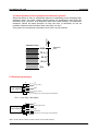
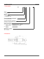
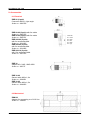
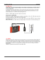
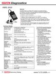
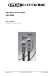
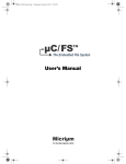
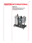
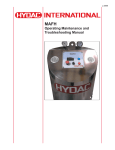
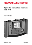
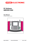
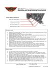
Aqua Sensor
AS 1000
User Manual
Part no.: 669705
Status: 09.04.2008
User Manual AS 1000
09.04.2008
CONTENTS
1. General ......................................................................................................................................... 3
2. Safety instructions......................................................................................................................... 3
3. Installation..................................................................................................................................... 3
4. Function ........................................................................................................................................ 4
4.1 Switching output ...................................................................................................................... 4
4.2 Analogue output....................................................................................................................... 4
4.3 Ideal saturation level in hydraulic and lubrication systems ...................................................... 5
5. Electrical connection ..................................................................................................................... 5
6. Technical specification.................................................................................................................. 6
7. Order details ................................................................................................................................. 7
8. Dimensions ................................................................................................................................... 7
9. Accessories................................................................................................................................... 8
9.1 Electrical .................................................................................................................................. 8
9.2 Mechanical............................................................................................................................... 8
10. Displays ...................................................................................................................................... 9
10.1 HDA 5500 .............................................................................................................................. 9
10.2 HMG 510 ............................................................................................................................... 9
10.3 HMG 3000 ........................................................................................................................... 10
10.4 CMWIN ................................................................................................................................ 10
11. Functions of the AS 1x08-P-000 (programmable) over and above the standard version ......... 11
11.1 Main menu ........................................................................................................................... 11
11.1.1 Output 1 and 2............................................................................................................... 12
11.1.2 System re-start .............................................................................................................. 12
12. Items supplied........................................................................................................................... 13
13. Important information - quick reference .................................................................................... 13
2
User Manual AS 1000
09.04.2008
1. General
If you have any queries regarding technical details or the suitability of the unit for your application,
please contact our technical sales department. The AS 1000 is individually calibrated on
computer-controlled test rigs and subjected to a final test. In this way we can guarantee that the
unit is fault-free on despatch and conforms to the given specifications.
However, if there is a cause for complaint, please return the unit to HYDAC Service outlining the
fault. Interference by anybody other than HYDAC personnel will invalidate all warranty claims.
2. Safety instructions
The Aqua Sensor AS 1000 presents no safety concerns when installed and operated in
accordance with this user manual. However, in order to avoid any risk to the operator or any
damage due to incorrect handling of the unit, please adhere strictly to the following safety
instructions:
• Before commissioning, please read the operating instructions. Ensure that the unit is suitable for
your application.
• During transportation, extra care must be taken to protect the unit from vibration and shock.
• The AS 1000 must not be put into service if any known defects, either electrical or mechanical,
are apparent.
• The unit must be installed exactly according to the instructions.
• Read the information on the type code label.
• Fault investigation and repairs must only be carried out by HYDAC Service.
• All relevant and generally recognised safety requirements must be adhered to.
• If the unit is not handled correctly, or if the operating instructions and specifications are not
adhered to, damage to the product or to personal injury may result.
3. Installation
The sensor can be installed directly in the hydraulic system via the threaded connection. The
recommended mounting position for hydraulic applications is vertical with the mechanical threaded
connection pointing upwards. When fitting, ensure that the sensor is completely submerged in the
fluid and that the fluid can circulate freely around the sensor. It is important, therefore, when tankmounting, to install the sensor in a position where there is guaranteed turbulence.
The electrical connection must be carried out by a qualified electrician according to the relevant
regulations of the country concerned (VDE 0100 in Germany).
The sensors of the AS 1000 series carry the CE mark. A declaration of conformity is available on
request. The sensor conforms to EMC standards: EN 61000-6-1, EN 61000-6-2, EN 61000-6-3
and EN 61000-6-4. The requirements of the standards are fulfilled only if the sensor housing is
earthed correctly by qualified personnel. When installing into a hydraulic block it is sufficient if the
block is earthed via the hydraulic system.
Additional assembly notes which, from experience, reduce the effect of electromagnetic
interference:
Make inline connections as short as possible.
Use screened cables (e.g. LIYCY 5 x 0.5 mm²).
The cable-screening must be fitted by a qualified person subject to the ambient conditions
and with the aim of suppressing interference.
Direct proximity to connecting lines of user units or electrical or electronic units causing
interference must be avoided as far as possible.
3
User Manual AS 1000
09.04.2008
4. Function
The Aqua Sensors in the series AS 1000 are water and temperature sensors for the continuous
and accurate online monitoring of hydraulic and lubrication fluids.
They measure the water content relative to the saturation concentration (saturation point) and read
out the degree of saturation in the range 0..100% as a 4..20mA analogue signal. A reading of 0%
would indicate a fluid free of water, whilst 100% would indicate a fluid that is saturated with water.
The capacitance sensor used in the AS 1000 absorbs water molecules from the fluid which results
in a change in capacitance of the sensor element. The measured value obtained represents the
level of saturation of the fluid in percent.
A thermal element on the sensor measures the temperature in the range
-25 ... +100°C. This is read out as a 4...20mA analogue signal, like the saturation level.
Outputs 1 and 2 can be configured independently of each other as switch or analogue outputs.
4.1 Switching output
With switching output 1 or switching output 2 the following variables can be monitored within
their limits:
Saturation level:
Temperature:
0 % ... 100 %
-25 °C ... +100 °C
"Switch on point" is used to indicate the value at which the output switches when the pre-set
value is exceeded.
"Switch off point" is used to indicate the value at which the output switches back when the
value falls below its pre-set level.
"Switching direction" is used to determine whether the output, when exceeding the pre-set
value, switches:
a) from GND to Ub (N/O function)
b) from Ub to GND (N/C function)
4.2 Analogue output
With analogue output 1 or analogue output 2 the following variables can be displayed within
their limits:
Saturation level:
Temperature:
0 % ... 100 %
-25 °C ... +100 °C
The outputs are always configured as current outputs (4 ... 20 mA).
4
User Manual AS 1000
09.04.2008
Free water
4.3 Ideal saturation level in hydraulic and lubrication systems
Since the effects of free (or emulsified) water are considerably more damaging than
dissolved water, the water content should always be significantly lower than the
saturation point. However, even dissolved water can cause damage,. All reasonable
measures should be taken therefore to keep the level of saturation as low as
possible. Hydraulic and lubrication fluids cannot be "too dry"!
As a guide, we recommend a saturation level of 45% for all systems.
Saturation level
Saturation
point
75 %
50 %
25 %
Dissolved water
100%
0%
5. Electrical connection
1
2
AS 1000-P
+Ub
Progr. output 1
3
GND
4
5
Progr. output 2
HSI* (do not connect during normal operation!)
RLmax = (UB-10V) / 20mA [kΩ]
1
2
AS 1000-C
+Ub
RL
3
4
5
Signal saturation level
GND
RL
Signal temp.
HSI* (do not connect during normal operation!)
* HSI = HYDAC Sensor Interface (HYDAC internal communication interface)
5
User Manual AS 1000
09.04.2008
6. Technical specification
Input data
Measuring range (saturation level)
Measuring range (temperature)
Operating pressure
Overload pressure
Parts in contact with the fluid
Output data
Saturation level
Output signal
Calibration accuracy
Accuracy when measuring in fluids
Pressure dependence
Output data
Temperature
Output signal
Accuracy
Switch output 1 and 2
Output signal
Switch level
Ambient conditions
Nominal temperature range (measurement of
saturation level)
Ambient temperature range
Temperature range of fluid
Viscosity range
Flow velocity
Fluid compatibility
- mark
Protection class to DIN 40050
Other data
Supply voltage
Residual ripple supply voltage
Mechanical connection
Torque value
Electrical connection
Pin 1: +Ub
Pin 2: analogue output 1 / switch output 1
Pin 3: 0V / GND
Pin 4: analogue output 2 / switch output 2
Pin 5: HSI
Reverse polarity protection of the supply voltage,
excess voltage, override and short circuit protection
Weight
Note:
0 .. 100 %
-25 .. +100 °C
max. 50 bar
max. 630 bar
Stainless steel, Viton / or EPDM seal,
ceramic with vapour-deposited metal
4 .. 20 mA
≤ ± 2 % FS max.
≤ ± 3 % FS typ.
+ 0.025 % FS/bar
4 .. 20 mA
≤ ± 2% FS max.
PNP switch output 1 A max
≤ UB
0 .. + 90 °C
-40 .. +100 °C
-40 .. +125 °C
1 .. 5000 cSt
< 5 m/s
Mineral oil based fluids,
synthetic and natural esters
EN 61000-6-1, EN 61000-6-2
EN 61000-6-3, EN 61000-6-4
IP 67
12 .. 32 V DC
≤5%
G3/8A DIN 3852
approx. 25 Nm
M12x1, 5 pole
Provided
approx. 145 g
FS (Full Scale) = relative to the full measuring range
6
User Manual AS 1000
09.04.2008
7. Order details
AS
1 X 0 8
-
X
-
000
Series
1 = Series 1000
Medium
0 = Mineral oils
1 = Phosphate ester
Type of connection, mechanical
0 = G 3/8A DIN 3852
Type of connection, electrical
8 = M12x1, 5-pole (without connector)
Signal technology
C = output 1 (Pin 2)
output 2 (Pin 4)
P = output 1
output 2
saturation level ( 4 .. 20 mA)
temperature (4 .. 20 mA)
programmable
programmable
Modification number
000 = standard
8. Dimensions
hex. AF27
M12x1 – 5 pole connection
7
User Manual AS 1000
09.04.2008
9. Accessories
9.1 Electrical
ZBE 08 (5-pole)
Connector M12x1, right-angle
Order no.: 6006786
ZBE 08-02 (5-pole) with 2m cable
Order no.: 6006792
ZBE 08-05 (5-pole) with 5m cable
Order no.: 6006791
ZBE 08S-02 (5-pole)
with 2m screened cable
Order no.: 6019455
ZBE 08S-05 (5-pole)
with 5m screened cable
Order no.: 6019456
ZBE 08S-10 (5-pole)
with 10m screened cable
Order no.: 6023102
Colour code:
Pin 1:
Pin 2:
Pin 3:
Pin 4:
brown
white
blue
black
Pin 5: grey
ZBE 36
Adaptor AS / HLB - HMG 3000
Order no.: 909737
ZBE 30-02
Sensor cable M12x1, 2m
Order no.: 6040851
ZBE 30-05
Sensor cable M12x1, 5m
Order no.: 6040852
9.2 Mechanical
ZBM 22
Adapter for connecting to a G1/2“ line
Order no.: 3248511
8
User Manual AS 1000
09.04.2008
10. Displays
10.1 HDA 5500
The HDA 5500, version HDA 5500-1-1-AC-000 or HDA 5500-1-1DC-000, is a display unit with 4 programmable switch outputs,
specially designed for use with the AS 1000.
In conjunction with the HDA 5500 it is possible to display the
actual measured values.
Order no.: 908869 HDA 5500-1-1-AC-000
Order no.: 908870 HDA 5500-1-1-DC-000
Connection to a HDA 5500
X1:
Pin 1: + supply HDA 5500
X1:
Pin 2: - supply HDA 5500
X2:
X2:
X2:
X2:
Pin 5:
Pin 6:
Pin 4:
Pin 2:
GND AS 1000
+12V supply AS 1000
temperature
saturation point
(blue)
(brown)
(black)
(white)
10.2 HMG 510
Portable 2-channel data recorder, specially designed to display measured values from HSIand SMART sensors.
In conjunction with the HMG 510 it is possible to display the actual measured values on the
display of the HMG 510.
Order no.: 909889 HMG 510-000
Connection to a HMG 510
Remove the supply cable from the electrical connection of the AS 1000 and screw the
connection adaptor AS / HLB "ZBE 36" into the sensor. Connect one of the inputs A or B of
the HMG 510 to the output of the "ZBE 36" using a sensor cable "ZBE 30-0x"
9
User Manual AS 1000
09.04.2008
10.3 HMG 3000
Portable data recorder with a full graphical colour display for displaying or recording measured
values of the AS 1000. In addition changes can be made to the parameters of the AS 1000
using the HMG 3000.
In conjunction with the HMG 3000 the actual measured values can be shown on the HMG
3000 display. The recordings can also be saved on the HMG 3000 and edited (for a more
detailed description, see HMG 3000 Operating Manual).
Order no.: 909437 HMG 3000-000-E (without accessories)
Connection to a HMG 3000
Remove the supply cable from the electrical connection of the AS 1000 and screw the
connection adaptor AS / HLB "ZBE 36" into the sensor.
Connect one of the inputs A to D of the HMG 3000 to the output "ZBE 36" using a sensor
cable "ZBE 30-0x".
When connecting to an HMG 3000 the voltage supply for the sensor is via the measuring unit.
10.4 CMWIN
Specially developed PC software which communicates via a communication bridge (HMG 510
or HMG 3000) with the AS 1000. Using the software, measurement curves can be transferred
to your PC, saved, displayed and edited or the actual measured values can be displayed. With
the AS 1000 "P" version, it is also possible to configure the sensor according to individual
requirements.
CMWIN is supplied with the HMG 510 and HMG 3000.
10
User Manual AS 1000
09.04.2008
11. Functions of the AS 1x08-P-000 (programmable)
over and above the standard version
In addition to the standard functions, it is possible to configure the AS 1000 "P" version using the
HMG 3000 and the PC software CMWIN under the menu point "Sensor dialogue".
The following menu navigation applies in this case and is identical in both the HMG 3000 and in the
PC software CMWIN:
Main menu
Analogue output 1
Output 1
Switching output 1
Analogue output 2
Output 2
Switching output 2
System re-start
11.1 Main menu
The AS 1000 supports German, English and French. Use the main menu to access the
following setup options of the sensor:
Output 1:
Configuration of output 1 as analogue or switching output
Output 2:
Configuration of output 2 as analogue or switching output
System re-start:
Re-start of the sensor
11
User Manual AS 1000
09.04.2008
11.1.1 Output 1 and 2
Each of the two menu points subdivides into a menu in which outputs 1 and 2 can be
configured independently of the other as either analogue or switching output.
• Analogue output
Here you can set the display parameters. The outputs are always configured as current
outputs (4 .. 20 mA).
Possible display parameters:
• Saturation level:
Display range:
0 .. 100 %
• Temperature:
Display range:
-25 .. +100°C
"Ok" is used to write back the changed data into the sensor. "Cancel" is used to discard the
data and to return to the previous menu.
• Switching output
This is used to set the parameters which are to be monitored, as well as the values of the
switch-on and switch-off points and the switch direction (N/C, N/O).
In the display area, you can select which of the following parameters are to be monitored
within their limits using the switch output:
• Saturation level:
Display range:
0 ... 100 %
• Temperature:
Display range:
-25 .. +100°C
In the "Switch on point“ box, the value is displayed at which the output switches when the
pre-set parameter is exceeded.
In the "Switch off point" box the value is displayed at which the output switches back
once the value falls below the pre-set parameter.
"Switch direction" is used to determine whether the output switches from GND to the
value of the supply voltage Vs (N/O function) or switches from the value of the supply
voltage Vs to GND (N/C function).
"Ok" is used to write back the changed data to the sensor. "Cancel" is used to discard the
data and to display the previous menu.
11.1.2 System re-start
Use this menu point to force the sensor to re-start. Afterwards all the settings previously
made become active. Use the "Ok" button to re-start. Use "Cancel" to return to the main
menu.
This should avoid making changes to the output configuration during operation which can
cause damage to the sensor. The error message which appears can be ignored. Use
"Cancel" to return to the main menu after the re-start.
12
User Manual AS 1000
09.04.2008
12. Items supplied
1 AS 1000 sensor
1 Operating Manual
13. Important information - quick reference
•
We recommend that for hydraulic applications, the sensor is fitted vertically with the
electrical plug pointing downwards.
•
When installing, please ensure that the sensor is completely submerged in the fluid and
that the fluid can circulate freely through the sensor.
•
Please ensure a constant flow and prevent the formation of air bubbles as much as
possible. If the oil is not flowing, the possibility of deviations in measurement is
increased.
13
User Manual AS 1000
09.04.2008
HYDAC ELECTRONIC GMBH
Hauptstr. 27
D-66128 Saarbrücken
Germany
Web: www.hydac.com
E-Mail: [email protected]
Tel.: +49 (0)6897 509-01
Fax.: +49 (0)6897 509-1726
HYDAC Service
For enquiries about repairs or alterations, please contact HYDAC Service.
HYDAC SERVICE GMBH
Hauptstr. 27
D-66128 Saarbrücken
Germany
Tel.:
Fax.:
+49 (0)6897 509-1936
+49 (0)6897 509-1933
Note
The information in this manual relates to the operating conditions and applications described. For
applications and operating conditions not described, please contact the relevant technical
department.
If you have any questions, suggestions, or encounter any problems of a technical nature, please
contact your Hydac representative.
All technical details are subject to change without notice.
14