1
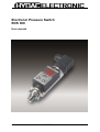
Electronic Pressure Switch
EDS 300
User manual
Stand 06.05.2009
HYDAC ELECTRONIC GMBH
Mat.Nr. 669666
Page 2 of 16
Content
1.
Functions of the EDS 300...............................................................................3
2.
Mounting..........................................................................................................3
3.
Operating keys on the membrane keypad ....................................................4
4.
Digital display..................................................................................................4
5.
Output function ...............................................................................................5
5.1 Switching outputs ............................................................................................................ 5
5.1.1 Switching point setting (SP).......................................................................................... 5
5.1.2 Window function setting (WIN) ........................................................................................ 5
5.2 Analogue output............................................................................................................... 6
5.3 Setting the Switching Points and Hystereses ............................................................... 6
5.4 Setting ranges of the switching points and/or hystereses .......................................... 6
6.
Basic settings..................................................................................................7
6.1 Altering the basic settings .............................................................................................. 7
6.2 Summary of the basic settings ....................................................................................... 8
7.
Programming enable ....................................................................................10
7.1 Altering the operating programming enable ............................................................... 10
7.2 Altering the main programming enable ....................................................................... 10
8.
Error messages.............................................................................................11
9.
Technical specifications...............................................................................12
10. Circuit diagram ..................................................................................................13
11. Model code.........................................................................................................14
12.
Accessories...................................................................................................15
12.1
12.2
For electrical connection ......................................................................................... 15
For mechanical connection ..................................................................................... 15
13.
Dimensions....................................................................................................16
Stand 06.05.2009
HYDAC ELECTRONIC GMBH
Mat.Nr. 669666
Page 3 of 16
1.
Functions of the EDS 300
Depending on the model, the unit offers the following functions:
• Display of the actual pressure, maximum value or a switching point.
• Switching the switching outputs according to the pressure and the pre-set switching
parameters.
• Analogue output
• Menu for basic settings (adapting the EDS 300 to the particular application)
• Two different types of programming enable
Three different output models are available:
• EDS 300 with 1 switching output (1.2 A load capacity, no analogue output)
• EDS 300 with 2 switching outputs (1.2 A load capacity, no analogue output)
• EDS 300 with 1 switching output (1.2 A load capacity) and 1 analogue output (4...20 mA)
2.
Mounting
The EDS 300 can be mounted directly onto a hydraulic block via the pressure connection
(7/16 SAE 4 female).
When used in critical applications (e.g. strong vibrations or knocks) the pressure connection
must be mechanically decoupled via a Minimess hose. Mounting clamps are available as an
accessory (see point 12.2 "Accessories - for mechanical connection").
The electrical connection should be carried out by a qualified electrician according to the
relevant regulations of the country concerned (VDE 0100 in Germany). The pressure switch
housing must be earthed properly at the same time. When fitted into a hydraulic block it is
sufficient if the block is earthed via the hydraulic system. In the case of Minimess hosemounting, the housing must be earthed separately.
Additional assembly notes which, from experience, reduce the effect of electromagnetic
interference:
• Make line connections as short as possible.
• Use screened lines (e.g. LIYCY 4 x 0.5 mm2)
• The cable screening must be fitted by qualified personnel subject to the ambient
conditions and with the aim of suppressing interference.
• Direct proximity to connecting lines of user units or electrical or electronic units causing
interference must be avoided as far as possible.
Stand 06.05.2009
HYDAC ELECTRONIC GMBH
Mat.Nr. 669666
Page 4 of 16
3.
Operating keys on the membrane keypad
HYDAC
EDS 300
4-digit
digital display
SP1
PSI
SP2
keys for setting switching
points, switch-back points and
additional functions
mode
4.
Digital display
After switching on the supply voltage, the unit briefly displays “EdS” followed by the current
pressure.
2s
In the basic settings the display can be altered. For example, the maximum value can be
permanently displayed. This is the largest measured value which has been recorded since
the unit was switched on or was last re-set. A switching point can likewise be permanently
displayed or the display can be set to be dark. Depending on the setting, "TOP", "S.P. 1",
"S.P. 2" or "OFF" appears briefly on the display following the switch-on message.
The actual pressure can be displayed briefly by pressing the
or the
key. This causes
the maximum value to be re-set.
Notes:
• If the actual pressure exceeds the nominal pressure of the unit, it can no longer be
displayed and the display begins to flash.
• If the actual pressure is below 1 % of the nominal range, then 0 is displayed.
Stand 06.05.2009
HYDAC ELECTRONIC GMBH
Mat.Nr. 669666
Page 5 of 16
5.
Output function
5.1 Switching outputs
The EDS 300 has 1 or 2 switching outputs. The following settings can be made under the
basic setting:
5.1.1
Switching point setting (SP)
One switching point and one hysteresis can be set for each switching output. The respective
output switches when the pre-set switching point is reached and switches back when the
pressure falls below the switch-back point. The switch-back point is determined by the preset hysteresis (switch-back point = switching point minus hysteresis).
Abbreviations:
"S.P.1", "S.P.2" = switching point 1 or 2
"h.Y.1", "h.Y.2" = hysteresis 1 or 2
5.1.2 Window function setting (WIN)
The window function enables a range to be monitored. For each switching output, in each
case an upper and a lower switching value can be input which determine the range.
The respective output switches when the pressure enters this range. Upon leaving the
range, i.e. when the switch-back value has been reached, the output switches back. The
lower switch-back value is just below the lower switching value (lower switching value minus
three times the increment, see point 5.4). The upper switch-back value is just above the
upper switching value (upper switching value plus three times the increment, see point 5.4).
The area between switching and switch-back value forms a safety zone which prevents
unwanted switching operations from occurring (e.g. triggered by pulsations from a pump).
Example for switching output 1 (normally open function):
P
Off
hi.1 plus 3xincrement
hi.1
Switch-back valuet
Switching value
Safety zone
On
On
Lo.1
Lo.1 minus 3xincrement
Switching value
Switch-back value
Safety zone
Off
t
ON
Off
Abbreviations:
"hi.1", "hi.2"
"Lo.1", "Lo.2"
= High level 1 or 2
= Low level 1 or 2
= upper switching value 1 or 2
= lower switching value 1 or 2
Note: The window function only operates correctly (switching on and off), when all switching
values (including the safety zone) are greater than 0 bar and lower than the nominal
pressure range.
Stand 06.05.2009
HYDAC ELECTRONIC GMBH
Mat.Nr. 669666
Page 6 of 16
5.2 Analogue output
On specified models, the EDS 300 provides one analogue output with a 4...20 mA signal.
5.3. Setting the Switching Points and Hystereses
• Press "mode" key
• "S.P.1" or "hi.1" is displayed
• Keep pressing the "mode" key until the required parameter is displayed (depending on
the basic setting: "S.P.1", "h.Y.1", "S.P.2", "h.Y.2", "hi.1", "Lo.1", "hi.2" or "Lo.2").
• After 2 seconds the actual setting flashes.
• Use the
or the
keys to alter the setting.
• Use the "mode" key to call up other parameters, if required, and alter the setting using
the
and the
keys.
• If no keys are pressed for 3 seconds, the display changes back and the settings are
saved.
+
mode
mode
press “mode” key
until the required
parameter is
reached.
display
2s
set switching point
=smaller value
=larger value
*
pressure
display
3s
Notes:
• If "LOC" appears in the display when trying to alter the settings, programming is disabled.
Corrective action: set programming enable to "ON"
(see point 7 "Programming enable")
• If the
or the
key is held down during alteration, the value automatically advances.
• If a setting has been altered, "PRG" appears briefly in the display when the display is
switched over. The new setting is then saved in the unit.
5.4
Setting ranges of the switching points and/or hystereses
Measuring range
in psi
-14 .. 75
0 .. 150
0 .. 1000
0 .. 3000
0 .. 6000
0 .. 9000
Switching point
and/or upper
critical value
in bar
-12.5 ..
75.0
3 .. 150
15 .. 1000
45 .. 3000
90 .. 6000
150 .. 9000
Hysteresis and/or
lower critical value
in bar
-0.5 ..
74.0
1 .. 148
5 .. 990
15 .. 2970
30 .. 5940
50 .. 8900
Increment *
in psi
0.5
1
5
20
30
50
* All ranges given in the table are adjustable by the increments shown.
Stand 06.05.2009
HYDAC ELECTRONIC GMBH
Mat.Nr. 669666
Page 7 of 16
6.
Basic settings
In order to adapt the unit to a particular application, the function of the EDS 300 can be
altered via several basic settings. These are combined in a menu.
6.1 Altering the basic settings
Important note: when the menu is activated no switching operations are carried out.
Switch off supply voltage or disconnect the unit from the supply voltage.
+
+
mode
mode
3s
press “mode” key and
hold down. Switch
on supply voltage
(hold key down for 3s)
mode
*
2s
display
(release
“mode” key)
press “mode” key until the
required menu point appears
in the display.
(for summary, see 6.2)
Use
or
to alter
setting, then select next
menu point.
To close the basic setting menu
Call up the menu point "END", set to "YES", the EDS 300 returns to the normal display
mode after 2 seconds.
Note:
If after about 50 seconds no keys have been pressed, the menu automatically closes down.
Any changes which may have been made will not be saved.
Stand 06.05.2009
HYDAC ELECTRONIC GMBH
Mat.Nr. 669666
Page 8 of 16
6.2 Summary of the basic settings
Setting
Display
Switching mode switching output 1 (Sm 1)
Setting
range
SP/ Win
Presetting
SP
ON/ OFF
ON
0.00..75s
0
0.00..75s
0
ACT/
Top/
S.P.1/
S.P.2/
OFF
ACT
YES/ NO
NO
Switching output 1 operates in switching
point / hysteresis function
Switching output 1 operates in window
function
Switching direction switching output 1 (S 1)
“ON”: normally open function.
“OFF”: normally closed function.
Switch-on delay switching output 1 (Ton 1)
Time in seconds which must elapse, once the
particular switching point has been reached or
exceeded, before switching will occur.
Switch-off delay switching output 1 (Toff 1)
Time in seconds which must elapse, once the pressure
has fallen below the particular switch-back point, before
switching will occur.
Switching output 2, as above
Primary display (Primary)
Display value which should remain permanently in the
display:
“ACT.”:
base pressure
“Top”:
pressure peak value
“S.P.1” or “S.P.2”:switching point 1 or 2
“OFF”:
display dark
(for function, see point 4 “Digital display”)
Calibration of sensor zero point (Calibrate)
“YES”: The base pressure is saved as the new zero
point. This is possible in the range +/- 3 % of
the unit’s nominal pressure range.
“new” appears in the display when a
calibration is carried out in the permissible
range, otherwise “Err” is displayed.
This function is useful for example if there is always a
residual pressure in the system which should however
be displayed as 0 bar.
Please note:
Following a zero point adjustment, for example, on a
600 bar unit, a pressure of up to 18 bar is displayed
as 0 bar. Before any work is carried out on the
hydraulic system, ensure that the system is depressurised.
Stand 06.05.2009
HYDAC ELECTRONIC GMBH
Mat.Nr. 669666
Page 9 of 16
Version number (Version)
Display of the current software version (for reference
only)
To close basic settings (End)
Stand 06.05.2009
HYDAC ELECTRONIC GMBH
YES/ NO
NO
Mat.Nr. 669666
Page 10 of 16
7.
Programming enable
The unit has 2 types of programming enable which must both be set to "ON" to change the
settings. The operating programming enable can be set or removed during operation. It
provides protection from unintentional alteration. A programming disable via the main
programming enable has the effect that no change to the settings can be carried out during
operation. This serves, for example, as a safety function or as protection against
unauthorised alterations.
7.1 Altering the operating programming enable
mode
mode
pressure
display
* *
*
3s
press both
arrow keys
simultaneously
and hold down
for 3 s
display
(release
arrow keys)
3s
use
or
to alter setting,
ON = programming possible
OFF = programming disabled
7.2 Altering the main programming enable
Switch off supply voltage or disconnect the unit from the supply voltage.
"main program state"
mode
mode
pressure
display
* *
*
3s
press both arrow
arrow keys
simultaneously
and hold down.
Switch on supply
voltage (hold keys
down for 3 s)
display
(release
arrow keys)
3s
use
or
to alter setting,
ON = programming possible
OFF = programming disabled
Note:
• If a setting has been changed "PRG" is displayed briefly when the display is switched
over. The new setting is then saved in the unit.
Stand 06.05.2009
HYDAC ELECTRONIC GMBH
Mat.Nr. 669666
Page 11 of 16
8.
Error messages
If an error is detected, then a corresponding error message appears which must be
acknowledged by pressing any key. Possible error messages are as follows:
E 01
The switching points and hystereses have been set in such a way that the resulting
switch-back point is no longer within the permissible setting range.
Corrective action:
E 10
A data error has been detected in the saved settings. Possible causes are strong
electromagnetic interference or a component fault.
Corrective action:
E 12
Check all the settings (programming enable, switching points,
switch-back points and basic settings) and correct these if
necessary. If the errors occur frequently, please contact Hydac
Service.
An error has been detected in the stored calibration data. Possible causes are
strong electromagnetic interference or a component fault.
Corrective action:
E 20
Correct the settings
Switch the unit off and on again. If the error message is still
displayed, the unit must be returned to the manufacturer for recalibration or repair.
A short-circuit has been detected on a switching output.
Corrective action:
Stand 06.05.2009
Eliminate the short circuit.
HYDAC ELECTRONIC GMBH
Mat.Nr. 669666
Page 12 of 16
9.
Technical specifications
Input data::
Measuring ranges:
Overload pressures:
Burst pressure:
Output data:
Accuracy (B.F.S.L.) display & analogue
including linearity & hysteresis
Repeatability:
Temperature drift: zero point max.
range max.
Analogue output:
Switching outputs:
Type:
Switching current:
Switching cycles:
Reaction time:
Ambient conditions:
Temperature range of medium:
Ambient temperature range:
Storage temperature range:
Compensated temperature range:
- mark:
Vibration resistance:
Shock resistance:
Other data:
Supply voltage EDS 356-1,2:
Supply voltage EDS 356-3:
Electrical connection:
Current consumption:
Safety type:
Hydraulic connection:
Parts in contact with medium:
Material of housing:
Display:
Weight:
-14 .. 75; 150; 1000; 3000; 6000; 9000 psi
150 % FS, max. 13000 psi
300 % FS
≤ ± 0.5 % B.F.S.L.
≤ ± 0.5 % FS max.
≤ ± 0.016 % / °F (≤ ± 0.03 % / °C)
≤ ± 0.016 % / °F (≤ ± 0.03 % / °C)
4 .. 20 mA, ohmic resistance ≤ 400 Ω
PNP transistor output
max. 1.2 A
≥ 100 million
approx. 10 ms
-13 .. 176 °F (-25 .. + 80 °C)
-13 .. 176 °F (-25 .. + 80 °C)
-40 .. 176 °F (-40 .. + 80 °C)
14 .. 158 °F (-10 .. + 70 °C)
EN 61000-6-1 / -2 / -3 / -4
approx. 10 g / 0..500 Hz
approx. 50 g / 1ms
12 .. 32 V DC
20 .. 32 V DC
plug M12x1
approx. 100 mA (without switching output)
IP 65
see model code
stainless steel
tube: stainless steel
keypad housing: PA6.6 Gf30
4-digit, 7-segment LED, red
approx. 300 g
Note:
FS (Full Scale) = relative to the full measuring range
B.F.S.L. = Best Fit Straight Line
Stand 06.05.2009
HYDAC ELECTRONIC GMBH
Mat.Nr. 669666
Page 13 of 16
10. Circuit diagram
Model with 1 switching output
+
1
EDS 356-1
12..32 V
20..32
-
Imax. 1.2 A
4
SP 1
3
Model with 2 switching outputs
+
Imax. 1.2 A
1
SP 1
EDS 356-2
12
.. 32 V
V
20..32
-
4
Imax. 1.2 A
3
2
SP 2
Model with 1 switching output and
1 analogue output
+
Imax. 1.2 A
1
EDS 356-3
20..32 V
-
4
SP 1
I = 4..20 mA
3
2
analogue
RL
Stand 06.05.2009
HYDAC ELECTRONIC GMBH
Mat.Nr. 669666
Page 14 of 16
11. Model code
EDS 3 5 6 - X - XXXX - XXX
Series
EDS 3 = 300 Series Electronic Pressure Switch
Mechanical connection
5 = SAE-4 female thread (7/16-20 UNF2B)
Electrical connection
6 = M12x1 plug, 4 pole (connector not included)
Output
1 = 1 Switching output
2 = 2 Switching outputs
3 = 1 Switching output an 1 Analog output
Pressure ranges
0089 (-14..75); 0150; 1000; 3000; 6000; 9000 psi
Modification number
400 = standard in psi
401 = vacuum in psi
Stand 06.05.2009
HYDAC ELECTRONIC GMBH
Mat.Nr. 669666
Page 15 of 16
12.
Accessories
12.1
For electrical connection
4-pole connector with flying leads,
M12x1, 90° angled
Female interface
All dimensions
are in inches and
(millimeters)
1.043 ( 26.5)
0.807 (20 .5)
Ø 0.433 (11.0)
1.528 (38.8 )
1 .24 (31.5)
3
4
2
1
M12x1
Ø 0 .571 (14.5)
Wire colors:
Pin 1: brown, Pin 2: white, Pin 3: blue, Pin 4: black
Available types:
12.2
ZBE 06-02: Female Screw-Lock Type 90° Connector (2 meter cord)
ZBE 06-05: Female Screw-Lock Type 90° Connector (5 meter cord)
For mechanical connection
ZBM 300
clamp for wall-mounting the EDS 300 (material: polypropylene)
Mounting:
• Glue damping strips into the recesses of
the base plate.
• Mount base plate, the top is indicated by
"OBEN", "TOP" and 2 arrows.
• Insert EDS 300.
• Fit clip (only one possible position) and
press hard on the cross-pieces until they
engage.
ZBM 310
clamp for wall-mounting the EDS 300 (material: polypropylene, aluminium
AlSi12, steel)
Mounting:
• Weld the steel base plate
• Mount EDS 300 in accordance with the
drawing
Stand 06.05.2009
HYDAC ELECTRONIC GMBH
Mat.Nr. 669666
Page 16 of 16
13.
Dimensions
HYDAC Technology Corporation
Electronic Division
2260 City Line Road
USA-Bethlehem, PA 18017
Phone.: (610) 266-0100
Fax:
(610) 266-3540
E-mail: [email protected]
Stand 06.05.2009
HYDAC ELECTRONIC GMBH
Mat.Nr. 669666