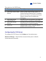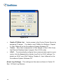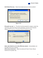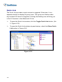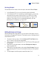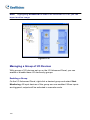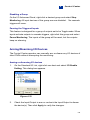
1
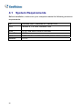
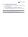
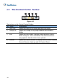
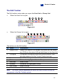
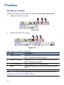
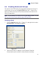
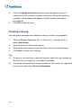
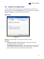
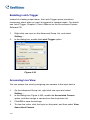
Chapter 4
Control Center
Control Center is a central monitoring station solution (CMS) that provides
the CMS operator with these major features:
•
Access to client DVRs (See Remote DVR)
•
Access to remote desktops (See Remote Desktop)
•
Display of up to 64 cameras from different DVRs on the same screen
(See Matrix View)
•
Remote playback (See Remote ViewLog)
•
Central management for I/O devices from different DVRs (See I/O
Central Panel)
4.1
System Requirements
Before installation, make sure your computer meets the following minimum
requirements:
OS
Windows 2000, Windows XP, Server 2003
CPU
Pentium 4, 2.6 GHz, 800MHz FSB
RAM
2 x 512 MB dual DDR400 SDRAM
Hard Disk
80 GB
VGA
NVIDIA GeForce4 MX440 64MB, 1024 x 768 resolution
Network
TCP/IP
98
4
4.2
1.
Control Center
Installing Control Center
Insert the CMS Software CD to your computer. It will automatically run
and a window appears.
2.
Select the Install V 8.0.0.0 Central Monitoring System item.
3.
Click Control Center System, and follow the on-screen instructions.
Note:
The Control Center application is provided with a USB dongle.
Make sure the dongle is tightly attached to your computer.
99
4.3
The Control Center Toolbar
1
2
3
4
Figure 4-1
The buttons on the Control Center Toolbar:
No. Name
Description
1
Host List
Opens the Host List to create and edit DVR hosts.
2
Group List
Opens the Group List to group cameras from different
DVRs.
3
Edit
Opens the Edit toolbar to display these buttons: Search
DVR, Configure, Save and Delete. The Add Host button
only appears after the Host List is opened.
4
Service
Opens the Service toolbar to display these buttons: Remote
Control, Remote ViewLog and I/O Central Panel.
100
Control Center
4
The Edit Toolbar
The Edit toolbar varies when you open the Host List or Group List.
•
When the Host List is open:
1
2
3
4
5
Figure 4-2
•
When the Group List is open
1
2
3
4
6
7
Figure 4-3
The buttons on the Edit toolbar:
No. Name
Description
1
Search DVR
Opens the Search DVR window, by which you can detect
2
Configure
any DVRs on the same LAN and add them to the Host List.
Configures the startup mode and screen position, and
change password for the Control Center services.
3
Save
4
Delete
Saves the changes made on the Host List and Group List.
Deletes the highlighted Host or Group.
5
Add Host
Adds a Host.
6
Rename
Renames the highlighted Group.
7
Add Group
Adds a Group.
Note:
The small toolbars appearing on both the Host List and Group List
correspond to the Edit Toolbar options.
101
The Service Toolbar
The Service Toolbar varies when you open the Host List or Group List.
•
When the Host List is open:
1
2
3
Figure 4-4
•
When the Group List is open:
4
2
3
Figure 4-5
The buttons on the Host List toolbar:
No. Name
1
Remote Control
Description
Highlight a host, and click this button to run Remote
DVR or Remote Desktop services.
2
Remote ViewLog
Highlight a Host or Group, and click this button to
open ViewLog for playback.
3
I/O Central Panel
4
Matrix
Click to open the I/O Central Panel.
Highlight a group, and click this button for a Matrix
View.
Note:
The small toolbars appearing on both the Host List and Group List
correspond to the Service Toolbar options.
102
4
4.4
Control Center
Creating Hosts and Groups
You need to create DVR hosts and groups before starting the services. To
create hosts, you can click the Search DVR button (No. 1, Figure 4-2) to
detect any DVR on the same LAN and then add them to the Host List. Or
follow the steps below.
Note:
For the Search DVR feature, the DVR host needs to open TCP port
5201 and the Control Center needs to open UDP port 5200.
Creating a Host
1.
Click the Host List button (No. 1, Figure 4-1), and right-click to select
Add Host DVR. This dialog box appears.
Figure 4-6
2.
Type the host name, IP address, ID and Password. Keep the
communication ports as default, unless otherwise necessary.
103
3.
Click the Update Information button to get the latest number of
cameras and I/O modules installed at the host. When the update is
complete, this message will appear: Update system information
successfully.
4.
Click OK to add the host.
Creating a Group
You can group cameras from different hosts by function or geography.
1.
Click the Group List button (No. 2, Figure 4-1), and right-click to
select Add Group.
2.
Type the name for the created group.
3.
Drag the desired cameras from the Host List to the created group.
4.
Click Save to store your settings.
Tip:
(1)
To enjoy a live view from a desired camera, right-click any camera on
the Host List or Group List, and select Live View.
(2)
To see the information of a single camera on the Group List, right-click
any camera, and select Device Information.
104
4
4.5
Control Center
System Configuration
You can configure the startup mode and screen position for the Control
Center services. Click the Configure button (No. 2, Figure 4-2), and select
System Configure to display the following dialog box.
[General]
Figure 4-7
[Startup]
Automatically runs the Control Center at startup.
[Layout]
Display host name in the Group List:
Displays the individual
camera’s host name on the Group List.
Save Window Position and Size:
Saves the position of the Control
Center toolbar and the size of Host List and Group List. The position
and size will be restored when the Control Center starts.
105
[Remote DVR]
Figure 4-8
[Panel Resolution]
Sets the resolution of the Remote DVR panel to 800 x
600, 1024 x 768 or 1280 x 1024.
[Position]
When the panel resolution is set to 1280 x 1024, align the
positions of the RemoteDVR window on screen.
[Active Camera]
starts.
106
Enable the desired cameras when the Remote DVR
4
Control Center
[Remote ViewLog]
Figure 4-9
[Panel Resolution]
Sets the resolution of the Remote ViewLog panel to
800 x 600, 1024 x 768 or 1280 x 1024.
[Position]
When the screen resolution is set to 1280 x 1024, align the
positions of the Remote ViewLog window on screen.
107
[Matrix]
Figure 4-10
[Position]
You can open up to four Matrix windows in one monitor or
separate four monitors at a time. Align the positions of four Matrix windows
on screen.
108
4
Control Center
[I/O Central Panel]
Figure 4-11
[Exit Option]
Automatically closes the I/O Central Panel when the Control
Center is shut down.
[Position]
When the screen resolution is set to 1280 x 1024, align the
position of the I/O Central Panel on screen.
109
4.6
Connecting to the Control Center
To configure the client DVR in order to access the Control Center remotely
through a network connection, click the Network button on the main screen,
point to Control Center Server, and then select Start Default Service or
Start Default Service for connection.
The Control Center Server Window
When the client DVR starts the Control Center Service (CCS) as described
above, the server will be minimized to the system tray. Click the server’s
icon
to restore its window.
1
2
3
4
5
Figure 4-12
110
4
Control Center
The controls on the CMS Server:
No. Name
Description
1
Stop All Service
Stops all Control Center Server services.
2
Start/Stop Control Center Starts or stops these services: Matrix, I/O
Service
Central Panel and Remote DVR. It indicates
that the user allows or not allows the Control
Center to access his I/O modules and
GV-System.
3
4
5
Start/Stop Remote
Indicates that the user allows or not allows the
ViewLog Service
Control Center to access his ViewLog files.
Start/Stop Desktop
Indicates that the user allows or not allows the
Service
Control Center to control his desktop.
Event List
Indicates login ID and IP address, service
activation and connection time.
Configuring the CCS Server
To configure the CCS Server, click Configure on the window menu.
[Network Settings]
Keep the three communication ports in defaults,
unless otherwise necessary.
111
Figure 4-13
Enable IP White List:
assigning IP ranges.
Limits access to the Control Center Server by
For details, see IP White List Settings, Chapter
6, User’s Manual on the Surveillance System Software CD.
Codec:
Sets video compression to Geo Mpeg4 or Geo H.264. Note
that Remote Desktop doesn’t support Geo H.264 codec.
UPnP:
To automatically configure three communication ports on your
router, click the Arrow button beside Log Port for UPnP settings. For
details on UPnP, see UPnP Setting, Chapter 6, User’s Manual on the
Surveillance System Software CD.
[Event Log Settings]
The settings are the same as those in Center V2.
See 1.8 Event Log Browser
112
4
[Set Default Service]
Control Center
Select the desired services to start by default.
Figure 4-14
[Prompt to accept …]
The client can be prompted to accept or reject the
connection when the Control Center attempts to access his GV-System
(Remote DVR service) or Desktop (Remote Desktop service).
Figure 4-15
[Auto start default service when Windows starts]
Automatically runs
the default services at startup.
[Hide when minimized]
Hides the minimized Control Center Server
window to the system tray.
113
4.7
Remote DVR
The Remote DVR service allows the Control Center to access client
GV-Systems and configure their settings remotely. This feature reduces the
trips to each client DVR individually.
Running the Remote DVR
1.
The client DVR must activate Control Center Service (No. 2, Figure
4-12) first.
2.
At the Control Center, highlight a DVR in the Host List.
Then click the Remote Control button
and select Remote DVR.
If the connection is established, the main screen of the client DVR will
display on the Control Center desktop. At the same time, the client DVR will
display the following message, advising the GV-System is in use and has
been locked.
Figure 4-16
If the client wants to interrupt the connection, he or she can click the button
at the bottom right corner. A valid ID and Password are required to
stop the connection.
Tip:
If you do not wish to overload the bandwidth by viewing all cameras
of the client DVR, you can choose to view certain cameras. There are two
ways to activate and deactivate cameras:
114
4
(1)
Control Center
Before connecting to the client DVR, in the Control Center, click the
Configure button
, select System Configure, and then click
the Remote DVR tab. In the Active Camera field, check or uncheck
desired cameras. Click OK to save to your settings.
(2)
When connecting to the client DVR, on the main screen of the client
DVR, click the Exit button, and then select Activate Camera. Check
or uncheck cameras.
Note:
Remote DVR currently doesn’t support audio output, PTZ and I/O
control.
115
4.8
Remote Desktop
Not only does Remote Desktop provide the Remote DVR feature of working
on client GV-Systems, but allow you to exit to Windows. Viewing the client
desktop as a website view, the center operator has a full control to client
GV-System and its operation system.
Running the Remote Desktop
1.
The client DVR must activate Remote Desktop Service (No. 4, Figure
4-12) first.
2.
At the Control Center, highlight a DVR in the Host List. Then click
the Remote Control button
, and select Remote Desktop.
When the connection is established, the client desktop will appear on the
Control Center desktop.
Note:
116
Remote Desktop currently doesn’t support the file transfer feature.
4
4.9
Control Center
Remote ViewLog
The Remote ViewLog service allows the Control Center to access the
ViewLogs of the client DVRs and play back event files.
Running the Remote ViewLog
1.
The client DVR must activate Remote ViewLog Service (No. 3,
Figure 4-12) first.
2.
At the Control Center, highlight a DVR in the Host List or a group in the
Group List. Then click the Remote ViewLog button
.
When the connection is established, the ViewLog of client DVR will appear
on the Control Center desktop. For details on ViewLog, see Chapter 3,
User’s Manual on the Surveillance System Software CD.
If highlighting a group for the Remote ViewLog service, you can access the
event files of up to 64 cameras. However, the Multi View of ViewLog can
only display up to 16 cameras. So you need to select the desired cameras
for Multi View mode. On the ViewLog function panel, click the Setting
button to display the System Configuration dialog box, and select the Multi
View tab. Then check the 16 cameras you want to display on the screen.
117
4.10
Matrix View
Matrix view allows the center operator to monitor up to 64 cameras from
different client DVRs on the same screen. Further, the operator can
remotely change camera’s monitoring status and properties. The Matrix
view provides these features:
•
Display of 1, 4, 9, 16, 32, 36, 48 or 64 cameras at a time
•
Display of up to 4 Matrix windows in one monitor or separate four
monitors at a time
•
Support for the remote configuration of camera status and properties
•
Support for the Camera Scan function
•
Access to client ViewLog for playback
Running Matrix View
1.
The client DVR must activate Control Center Service (No.2, Figure
4-12) first.
2.
At the Control Center, highlight a Group and select the Matrix button
. The Matrix window appears.
118
4
1
2
3
4
Control Center
6
5
7
Figure 4-17
The controls on the Matrix window:
No. Name
Description
1
Exit
Closes or minimizes the Matrix window.
2
Screen Division Select screen divisions with the choices of 1, 4, 9, 16, 32,
3
Date/Time
Indicates the current date and time.
4
Monitor
Starts or stops monitoring.
5
Configure
Access the Matrix settings and camera properties.
6
ViewLog
Opens ViewLog.
7
Camera Scan
Rotates through screen divisions.
36, 48 or 64 channels.
119
Configuring Matrix View
On the Matrix window, click the Configure button (No. 5, Figure 4-17).
[System Configure]
Figure 4-18
Caption:
Displays the ID, Location or Camera Name stamp on
screen.
Camera Scan:
Sets the rotation interval between cameras. Click the
Arrow button to set rotation mode of 1, 4 or 9 channels.
DirectX:
Sets the DirectDraw function.
[Camera Configure]
Adjusts the properties and recording settings of
cameras.
[Video Attributes]
[Image Quality]
Adjusts video attributes of cameras.
Adjusts the video quality with the choices of Best, Normal
and Low. The better quality will result in bigger image size and need bigger
bandwidth.
[Auto Retry when Connection Broken]
Automatically reconnects when
the connection between the Matrix View and cameras is lost.
120
4
4.11
Control Center
I/O Central Panel
The I/O Central Panel provides a centrally managing solution for I/O
devices from different DVRs. Its major features are:
•
Group I/O devices from different DVRs
•
Trigger I/O devices in cascade mode
•
Monitor different I/O cascade configurations at different times of the
day
•
Quick access triggered I/O devices by a Quick Link window
Note:
The Advanced I/O Panel at the client DVR and the I/O Central
Panel at the Control Center can conflict each other. It’s recommended that
the client DVR cleans up the settings in the Advanced I/O Panel and
renders the I/O control to the Control Center.
Running the I/O Central Panel
1.
The client DVR must activate Control Center Service (No. 2, Figure
4-12) first.
2.
Click the I/O Central Panel
on the Control Center toolbar.
When the connection is established, the I/O Central Panel will display on
the Control Center desktop.
121
The I/O Central Panel
1
2
3
4
5
6
7
8
10
9
Figure 4-19
The controls on the I/O Central Panel:
No. Name
Description
1
Configure
Accesses Panel and Schedule settings.
2
Mode Schedule
Starts/stops Mode Schedule.
3
Toggle Quick Link
Displays the Quick Link window for quick access
to triggered I/O devices.
4
Advanced I/O List Style
Displays the Advanced I/O List in various styles:
5
Expand Tree Row
Expands tree branches.
6
Collapse Tree Row
Collapses tree branches.
7
Mode
Configures various cascade modes.
8
Standard I/O List
Displays connected I/O modules.
9
Advanced I/O List
Groups I/O devices in cascade mode.
View/Edit, Icon and Detail.
122
4
Control Center
Creating a Group for Cascade Triggers
You can group I/O devices by function or geography. Further, the group
allows cascade triggers, meaning that the trigger actions of one trigger can
activate another trigger.
For this example, you might have a group called “Entrance” that contains all
I/O devices installed at entrances. The “Entrance” group might contain other
sub groups, each of which contains just the related I/O devices in various
geographic locations:
Group containing all I/O devices installed at entrances
Input 2 installed at the front entrance
Output 1 sub group at the kitchen
Output 3 sub group at the garage
Figure 4-20
When Input 2 is triggered, it will trigger Output 1 and Output 3 sub groups,
and Output 1 will trigger Output 2 in a cascade series.
Creating a Group:
1.
Right-click on Advanced I/O List, and then select Add A Group. This
dialog box appears.
123
Figure 4-21
Group Name:
Names the group.
Invoke Alarm:
Invokes the computer alarm on I/O trigger.
Select a sound from the drop-down list.
Enable advanced logical input in Multicam:
See The
Advanced Logical Input Status option, later in this chapter.
2.
Click Save to apply the settings, and return to the panel.
3.
To create a cascading hierarchy, drag the desired inputs/outputs from
the left Standard I/O List to the group.
Note:
In the cascading hierarchy, each input can only be used once while
the same output can be used repeatedly.
Editing a Group:
To modify group settings, right-click a group, and select View/Edit. This
dialog box appears.
124
4
Control Center
Figure 4-22
[Group Name] As described in Figure 4-21.
[Group Notify Setting]
As described in Figure 4-21.
[Current Pin Setting] To enable this option, highlight an I/O device from the
group list at the bottom.
Trigger Associated Outputs: Triggers outputs in cascade mode.
Click the Finger tab to apply the change to all I/O devices at the same
group.
Change Icon: To enable this option, select one of two displayed icons:
Normal or Trigger. Click the Change Icon tab to change an icon. Click
the Finger tab to apply the change to all I/O devices at the same
group.
125
Editing an I/O Device:
In addition to editing groups, you can also edit the settings of individual I/O
device. Right-click an I/O device, and select Setting. This dialog box
appears.
Figure 4-23
[Display Setting] You can define the nature of I/O devices by colors. Note
that the setting only affects the Detail style of the Advanced I/O List (No. 4,
Figure 4-19).
Alarm Level drop-down list: Click the drop-down list, and select one
of the six default colors: Fire, Smog, Vibration, Intruder, Motion and
Emergency. For the Level Undefined option, select Text Color or
Background Color, and then click the Input/Output drop-down list to
change its color.
[Trigger Setting]
Trigger Associated Outputs: Triggers outputs in cascade mode.
126
4
Control Center
Configuring the Advanced I/O Panel
On the panel toolbar, click the Configure button, and select Panel Setting.
This dialog box appears.
Figure 4-24
[Startup]
Show Quick Link:
Opens the Quick Link window at panel startup.
Start Schedule Monitoring:
Starts Mode Schedule at panel startup.
For details, see Setting up Mode Schedule below.
[Layout]
Show Host Name:
Displays the host name of each I/O device on the
Advanced I/O List.
Use User-defined Text:
Allows you to modify the text of Alarm Level
(see Figure 4-23).
Setting up Mode Schedule
The Mode Schedule allows you to monitor different I/O cascade
configurations at different time. For example, you may want I/O cascade
triggers one way during business hours and another way for non-business
hours. Modes can be switched automatically at a scheduled time.
127
Creating a Mode:
1.
Click the Mode drop-down list (No. 7, Figure 4-19), and select More
Edit. This dialog box appears.
Figure 4-25
2.
Click Add, and name the created mode. You can create up to 100
modes.
3.
Click Save to return to the panel.
4.
Select the created mode from the Mode drop-down list, and create the
groups in the Advanced I/O List. For details, see Creating a Group for
Cascade Triggers earlier in this chapter.
Creating a Mode Schedule:
Define the times and days you like the panel to switch modes.
1.
On the panel toolbar, click the Configure button, and select Schedule
Setting. This dialog box appears.
128
4
Figure
2.
Control Center
4-26
Click Add to create a schedule. This dialog box appears.
Figure 4-27
Name: Type a name for the schedule.
Mode: Select a mode from the drop-down list.
Time: Define a time period you want the mode to run.
Days: Check the day box(es) you want the mode to run.
3.
Click OK to apply the settings, and click Save to return to the panel.
4.
To start the mode schedule, click the Mode Schedule button (No. 2,
Figure 4-19), and then select Mode Schedule Start.
129
Quick Link
The Quick Link provides a quick access to triggered I/O devices. It is a
separate window to display all group icons. The group icon flashes when
any included I/O device is triggered. Clicking the flashing icon will bring you
to the I/O location in the Advanced I/O List.
To open the Quick Link window, click the Toggle Quick Link button. (No.
3, Figure 4-19).
To open the Quick Link window at panel startup, check the Show Quick
Link option in Figure 4-24.
Figure 4-28
130
4
Control Center
Forcing Output
To manually force an output, click one output, and select Force Output.
In the Standard I/O List, you can force the output individually.
In the Advanced I/O List, considering cascade triggers, you can only
manually force the output at the top level, e.g. Figure 4-29. Other
outputs at sub levels cannot be forced manually, e.g. Figure 4-30.
However, if the output is not in a cascading hierarchy, you can
definitely force it manually, e.g. Figure 4-31
Figure 4-29
Figure 4-30
Figure 4-31
Editing Background Image
With the Background Image feature, you can import a floor plan to lay out
the locations of triggered I/O devices. This feature works in the Icon style of
the Advanced I/O List.
1.
To switch to the Icon style, click the Advanced I/O List Style button
(No. 4, Figure 4-19) and then select Icon.
2.
Select a group in the Advanced I/O List. The I/O icons of this group will
be displayed.
3.
Right-click on the right screen, and select Background Image to
import a graphic file.
4.
Right-click on the right screen, and uncheck Auto Arrange. Now you
can freely drag the I/O icons to the desired locations on the imported
map.
5.
To add images to another group, repeat the steps 2 to 4.
131
Note:
Highlighting Advanced I/O List in the Advanced I/O List, you can
import another image.
Figure 4-32
Managing a Group of I/O Devices
With groups of I/O devices set up on the I/O Advanced Panel, you can
enable or disable these I/O devices by groups.
Enabling a Group
On the I/O Advanced Panel, right-click a desired group and select Start
Monitoring. All input devices of this group are now enabled. When inputs
are triggered, outputs will be activated in cascade mode.
132
4
Control Center
Disabling a Group
On the I/O Advanced Panel, right-click a desired group and select Stop
Monitoring. All input devices of this group are now disabled.
No cascade
triggers will occur.
Pausing the Triggered Inputs
This feature is designed for a group of outputs set to be Toggle mode. When
inputs activate outputs in cascade triggers, right-click this group and select
Pause Monitoring. The inputs of the group will be reset, but the outputs
keep on alarming.
Arming/Disarming I/O Devices
The Control Center operator can manually arm or disarm any I/O devices of
client DVRs without interrupting the monitoring.
Arming or disarming I/O devices
1.
On the Standard I/O List, right-click one host and select I/O Enable
Setting. This dialog box appears.
Figure 4-33
2.
Check the Input/Output to arm or uncheck the Input/Output to disarm
the device(s). Then click Apply to verify the changes.
133
Enabling Latch Trigger
Instead of a lasting output alarm, the Latch Trigger option provides a
momentary alarm when an input is triggered in cascade mode. For details,
see Latch Trigger, Chapter 2, User’s Manual on the Surveillance System
Software CD.
1.
Right-click one input on the Advanced Group List, and select
Setting….
2.
In the dialog box, enable the Latch Trigger option.
Figure 4-34
Accessing Live View
You can access live view by assigning one camera to the input device.
1.
On the Advanced Group List, right-click one input and select
Setting….
2.
In the dialog box (Figure 4-340, enable the Associated Camera
option, and then assign a camera from the drop-down list.
3.
Click OK to save the settings.
4.
To view live video, click that input on the panel, and then select View
Associated Camera.
134