1
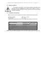
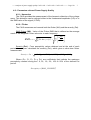
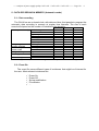
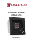
ANALYZER OF POWER SUPPLY QUALITY CAVA Series (251 / 252 / 253) USER’S MANUAL ( M98120201-20-09A ) (c) CIRCUTOR S.A. ----- Analyzer of power supply quality CAVA-251 / CAVA-252 / CAVA-253 ------- Page No. 1 CONTENTS OF THE CAVA-251 USER’S MANUAL page 1.BASIC INSTRUCTIONS ...................................................................................................................... 2 1.1.- Check the contents of your package ...................................................................................................... 2 1.2.- Safety conditions .................................................................................................................................. 3 1.3.- Connection instructions ........................................................................................................................ 3 2.- MAIN FEATURES ............................................................................................................................... 4 3.- CAVA MODELS .................................................................................................................................. 5 4.VARIABLES MEASURED AND RECORDED BY THE CAVA.......................................................... 6 4.1.- Instantaneous variables measured and calculated. ................................................................................. 6 4.2.- Parameters referred Power Supply Quality............................................................................................ 7 4.2.1.- Harmonics ................................................................................................................................... 7 4.2.2.- Flicker.......................................................................................................................................... 7 4.2.3.- Voltage sags ............................................................................................................................... 8 4.2.4.- Line interruptions ........................................................................................................................ 8 4.2.5.- Percentage of Voltage Quality .................................................................................................. 8 5.DATA RECORDING IN MEMORY (Automatic mode)........................................................................ 9 5.1.- Data recording...................................................................................................................................... 9 5.2.- Event file.............................................................................................................................................. 9 6.INSTALLATION AND STARTUP..................................................................................................... 10 6.1.- Installing the CAVA........................................................................................................................... 10 6.2.- CAVA connection procedure .............................................................................................................. 11 7.OPERATION MODE.......................................................................................................................... 12 7.1.- Communications................................................................................................................................. 12 7.2.- Setup procedure .................................................................................................................................. 13 8.- SPECIFICATIONS ............................................................................................................................. 15 9.- SAFETY CONSIDERATIONS 10.- MAINTENANCE ............................................................................................................................... 16 11.- TECHNICAL SERVICE ..................................................................................................................... 16 ....................................................................................... 16 ----- Analyzer of power supply quality CAVA-251 / CAVA-252 / CAVA-253 ------- Page No. 2 1.- BASIC INSTRUCTIONS This manual is aimed to familiarize de user with the operation of the measuring analyzers model CAVA in order to get the best from its features. CAVA analyzers have been built with components incorporating the most advanced technology in microelectronics and offer benchtop features over the market in measurement and recording of electrical magnitudes for the control of the quality of L.V. power systems. You are kindly requested to carefully read this manual before connecting and powering the analyzer in order to avoid irreversible damage which might be caused by an improper connection. 1.1.- Check the contents of your package After receiving the analyzer, please check the following points: a) The analyzer model corresponds with your order specifications. b) After unpacking, check that the instrument has not been damaged in transit. c) The standard set includes the following items: 1 CAVA unit (Ordered model) 1 Power supply cord 1 RS-232 communication cable. 1 Instruction manual. 3.5” floppy disks with the software for PC ----- Analyzer of power supply quality CAVA-251 / CAVA-252 / CAVA-253 ------- Page No. 3 1.2.- Safety conditions The manual you hold in your hands contains information and warnings about the CAVA that the user should respect in order to guarantee a proper operation of all the instrument functions and keep its safety conditions. 1.3.- Connection instructions Before powering and connecting the analyzer check the following points: a) Supply voltage: 230 V a.c., ± 15 % b) Frequency: 50...60 Hz. c) Maximum measurable current: according to the ammeter clamp used Clamp CP-2000-200 Clamp CPR-1000 Clamp CPR-500 Clamp CP-200 (M1-U) Clamp CP-100 (M1-U) Clamp CP-5 20 to 2000 A a.c. (switch at 2000) 2 to 200 A a.c. (switch at 200) 10 to 1000 A a.c. 5 to 500 A a.c. 2 to 200 A a.c. 1 to 100 A a.c. 50 mA to 5 A a.c. NOTE: It is advisable to measure close to full-scale value to get better accuracy. ----- Analyzer of power supply quality CAVA-251 / CAVA-252 / CAVA-253 ------- Page No. 4 2.- MAIN FEATURES CAVA series meters for the analysis of power supply quality are programmable instruments that measure, calculate and save in memory the main quality parameters of single-phase power systems. The set-up procedure of this instruments is performed by means of a P.C.. Before powering the analyzer, please carefully read sections referred to CONNECTIONS AND SET-UP to choose the most appropriate operation mode for your requirements. The CAVA measures in true R.M.S. mode, through the own power supply and external, .../2V c.a., ammeter clamps (the input current is not used in the CAVA-251) The CAVA collects data in a 1 Mb internal memory for a further downloading to a PC. Measured and calculated data are periodically saved on that memory at user-definable time intervals (from 5 s to 4 h). ----- Analyzer of power supply quality CAVA-251 / CAVA-252 / CAVA-253 ------- Page No. 5 - OTHER FEATURES - Low size instrument. True R.M.S. measuring mode. Recording of maximum and minimum value. Led for communication indication. Led for indication of recording process state (Store on/Store off) Capture of voltage sags and voltage dropouts. Measurement of harmonic distortion (THD or D). Measurement of Flicker. 3.- CAVA MODELS Different CAVA models are available according to measured and recorded parameters: CAVA Model Features 7 71 091 CAVA-251 Voltage Quality + Voltage 7 71 092 CAVA-252 Voltage Quality + Voltage + Current 7 71 093 CAVA -253 Voltage Quality + Voltage + Power Voltage Quality involves detection of voltage sags and voltage dropouts, as well as, harmonic distortion and flicker measurement. ----- Analyzer of power supply quality CAVA-251 / CAVA-252 / CAVA-253 ------- Page No. 6 4.- VARIABLES MEASURED AND RECORDED BY THE CAVA 4.1.- Instantaneous variables measured and calculated. - - VOLTAGE, RMS value.. 2 1 Vn = Vrms = u (t ) dt ; T [ Vrms = N 1 2 1 (u ) N CURRENT, RMS value (CAVA-252 & CAVA-253). 2 1 N 1 i (t ) dt ; [ Irms = In = Irms = 1 (i T N - ACTIVE POWER (CAVA-253). 1 N 1 Pn = u(t ) i (t ) dt ; [ P = 1 u i ] T N - POWER FACTOR (of each phase): PF1, PF2 & PF3. Pn PFn = Irms Urms - 2 ) ] ] REACTIVE POWER: Inductive and capacitive (CAVA-253) Value measured from the current signal 90 º shifted with respect to voltage signal. 1 u(t ) i (t / 2) dt Qn = T - FREQUENCY (Hz). ----- Analyzer of power supply quality CAVA-251 / CAVA-252 / CAVA-253 ------- Page No. 7 4.2.- Parameters referred Power Supply Quality 4.2.1.- Harmonics The CAVA provides the measurement of the harmonic distortion of the voltage wave. This distortion can be referred either to the fundamental amplitude (%D) or to the RMS value of the signal (%THD). 4.2.2.- Flicker The CAVA measures and records both the flicker (WA) and the severity (Pst). RMS Flicker (WA) : Value of the Flicker RMS that is defined as the average result of the weighted Flicker value due to each frequency. N RMS Flic ker Flic ker weighted 1 n 2 dVn % N V 1 FTn 2 Severity (Pst) : From perceptivity values obtained and at the end of each period the analyzer calculates the severity (Pst), which gives a short-term flicker measurement. Severity Pst 0,0314 P0.1 0,0525P1 0,0657 P3 0,28 P10 0,08 P50 Where (P0.1, P1, P3, P10 y P50) are coefficients that indicate the maximum perceptivity reached during the l 0,1%, 1%, 3%, 10% & 50% of the defined Pst period. 2 Perceptivity RMS _ FLICKER ----- Analyzer of power supply quality CAVA-251 / CAVA-252 / CAVA-253 ------- Page No. 8 4.2.3.- Voltage sags Voltage sags are defined as these cases where the R.M.S. value of a voltage semicycle is lower a pre-defined voltage value. The CAVA will inform about the number of semicycles having a R.M.S. value lower than the preset value that have been detected. The CAVA will also provide the number of intervals these voltage sags have occurred within. 4.2.4.- Line interruptions The CAVA is also equipped with a counter to give the number of cycles within the last period where a voltage dropout has occurred. The CAVA will also provide the number of intervals these voltage dropouts have occurred within. Moreover, the CAVA will save into an internal file all above mentioned events, together with the type and occurrence time of each event. 4.2.5.- Percentage of Voltage Quality The CAVA provides a value of the percentage of cycles presenting no event incidence (nor voltage sag neither voltage dropout) referred to the total of cycles within the set period. Voltage Quality No. of cycles wih no event 100 Total of cycles in the period ----- Analyzer of power supply quality CAVA-251 / CAVA-252 / CAVA-253 ------- Page No. 9 5.- DATA RECORDING IN MEMORY (Automatic mode) 5.1.- Data recording The CAVA has an on-board clock, with date and time, that permits to program the automatic data recording in memory at regular time intervals. The size of each record will depend on the number of variables to be stored in. Electric parameters (*) R.M.S. Voltage Current Apparent power Active power Reactive power Power Factor Frequency Voltage sags/ No. of cycles Voltage dropouts Intervals Line interruptions/ No. of cycles Power on/off Intervals Voltage Quality % cycles with no event Flicker (*) WA Pst Harmonics (*) THD CAVA-251 x CAVA-252 x x x x x x x x x x x x x x x x x x x x CAVA-253 x x x x x x x x x x x x x x x (*) maximum, minimum and average values of the period are saved in memory. 5.2.- Event file The event file saves different types of incidences that might be of interest for the user. Most relevant incidences are: Power On Power Off Set-up modification File deletion ... ----- Analyzer of power supply quality CAVA-251 / CAVA-252 / CAVA-253 ------- Page No. 10 6.- INSTALLATION AND STARTUP The manual you hold in your hands contains information and warnings that the user should respect in order to guarantee a proper operation of all the instrument functions and keep its safety conditions. Whether the instrument is not used according to manufacturer’s specifications, the protection of the instrument can be damaged. When any protection failure is suspected to exist or external damages are observed, the instrument must be immediately put out of service. Contact then with a qualified service representative. 6.1.- Installing the CAVA Before powering and connecting the analyzer, check the following points: a.- Supply/measuring voltage: - Single-phase voltage: 230 V a.c., ± 15 % Frequency : 50...60 Hz Burden : 3 VA b.- Maximum measurable current: according to the ammeter clamp used c.- Working conditions: - Operation temperature: 0 to 50 ºC - Operation humidity : 25 to 80 % RH e.- Safety : Designed to meet class III as per EN 61010 . Note that with the instrument powered on, cover opening or elements removal actions may allow accessing dangerous parts. ----- Analyzer of power supply quality CAVA-251 / CAVA-252 / CAVA-253 ------- Page No. 11 6.2.- CAVA connection procedure 1 2 3 4 5 6 Supply/Measurement Clamp connector Hold / Run led Communications led Hold / Run switch RS-232 Supply/Measurement: Voltage measurement is done from the own instrument’s supply. Check that the monitored power system is within allowable voltage limits of the analyzer. Clamp connector: This connector is used for the input of the ammeter clamp in models CAVA-252 & 253. Since the model CAVA-251 does not measures current, this connector is not used. The primary of the ammeter clamp in use must be set. During the installation process, note that the current direction through the line must coincide with the arrow marked on the clamp, otherwise, no power value will be recorded by the CAVA-253. Hold / Run led: This led indicates several operation modes: Whether the led is quickly blinking: a reset action is being carried out. Whether the led is blinking once per second: the analyzer has detected the switch at the “Run” position and this is storing data into the internal memory. Whether the led is always on and is not blinking: the analyzer has detected the switch at the ““Hold”” position and no data is being stored into the internal memory. Communications led: This led must be on while the analyzer is communicating with the P.C. Hold / Run switch: The position of this switch is only considered when powering up the analyzer. If at this moment the switch is at “Run”, the analyzer will record data into the internal memory, otherwise, if the switch is at “Hold” no data will be stored into the internal memory. RS-232: Connector for the communication and data downloading to a P.C. ----- Analyzer of power supply quality CAVA-251 / CAVA-252 / CAVA-253 ------- Page No. 12 7.- OPERATION MODE Before connecting the analyzer to a single-phase power system in order to record data or to transfer data to a P.C. check the “Hold/Run” switch to be at the right position. The position of this switch is only considered when powering up the analyzer. No later modification of the switch position will be effective once the analyzer is already running. It is advisable to observe the “Hold / Run” led to check that the analyzer is at the right operation mode according to our requirements (See section 6.2.-) The position of this switch is only considered when powering up the analyzer. 7.1.- Communications Setup procedure and data retrieval can only be performed through the RS-232 serial port in the CAVA; therefore, the configuration of the serial port of the PC and the CAVA must entirely coincide. The default configuration of the CAVA serial port is: Peripheral : 00 Communication parameters: 9.600 / 7 / N / 1 The CAVA only permits to modify the baud rate. Available baud rates are: 2400, 4800, 9600 & 19200 bauds When setting the data management software for the CAVA in the PC, the serial port used to communicate to the CAVA (Com 1, Com 2) must be correctly defined. The software will automatically check at different baud rates whether a CAVA is connected to the set port. ----- Analyzer of power supply quality CAVA-251 / CAVA-252 / CAVA-253 ------- Page No. 13 7.2.- Setup procedure A correct operation of the CAVA will depend on a right setup and connection actions. Parameters to be user-programmed through the appropriate PC software are following ones: Time: Time of the on-board analyzer clock. A right set is important to get correct information about the time that difference incidences occurred. Communications: To modify the baud rate when communicating to the P.C. Rated voltage: The rated voltage of the single-phase power system to be monitored by the CAVA. This point is very important since determine limits for the analysis of power supply quality. Time constant for voltage measurement(seg): The CAVA is set by default to provide the average value of the voltage for a period of one second. If required, this integration time can be modified just setting at this option the desired period is seconds. Voltage threshold: For some application it is not effective to monitor the maximum/minimum absolute value of the voltage but to record the percentage related to the whole period (x% of the period) that a maximum value has been exceeded, or that a minimum value has not been exceeded. If the maximum voltage value of reference is desired to be the absolute one, then the value 0% must be set. Quality threshold: % of the rated voltage. The analyzer counts the number of cycles whose R.M.S. value is within these limits. According to the number of right cycles the CAVA will give the percentage of voltage quality. Voltage sag and dropout threshold: % of the rated voltage. Every cycle whose R.M.S. value is below this limit is stated to be voltage sag or dropout. ----- Analyzer of power supply quality CAVA-251 / CAVA-252 / CAVA-253 ------- Page No. 14 Primary of the current transformer (CAVA-252 & CAVA-253): The primary of the ammeter clamp used for measuring must be set to obtain proper measured values. Time constant for current measurement (CAVA-252 y CAVA-253): The CAVA is set by default to provide the average value of the current for a period of one second. If required, this integration time can be modified just setting at this option the desired period is seconds. Rated frequency: The rated frequency of the monitored power system must be set to obtain right data when measuring instantaneous values. Time constant for frequency measurement (CAVA-252 & CAVA-253): The CAVA is set by default to provide the average value of the frequency for a period of one second. If required, this integration time can be modified just setting at this option the desired period is seconds. THD/D: Set here the distortion value measuring method: % D -> Harmonic distortion referred to the fundamental value. % THD -> Harmonic distortion referred to the R.M.S. value. Period: Integration period for data recording in memory. Campaign: This option enables to set different measurements into the same file. ----- Analyzer of power supply quality CAVA-251 / CAVA-252 / CAVA-253 ------- Page No. 8.- SPECIFICATIONS Supply/measuring circuit Single-phase 230 V c.a. Voltage tolerance: ±15 % Frequency: 50 ... 60 Hz Burden ............................ 3 VA Operation temperature range ......... 0 to 50 º C Current measurement .............. according to ammeter clamp Accuracy class: Voltage ............................... 0.5 % or readout Current ................................ 0.5 % or readout Powers ................................ 1 % or readout Test conditions for accuracy determination: - Ammeter clamps not included. - Ambient temperature: from + 5 ºC to + 45 ºC Dimensions : 136 x 70 x 57 mm - Safety ................................ Category III, as per EN-61010 Standards: EN 60664, VDE 0110, UL 94, EN 60801, EN 50081-1, EN-61010-1 , EN 50082-1, EN 60868 15 ----- Analyzer of power supply quality CAVA-251 / CAVA-252 / CAVA-253 ------- Page No. 16 9.- SAFETY CONSIDERATIONS The user should take into account all installation instructions referred in sections INSTALLATION AND START-UP and SPECIFICATIONS of this manual. Note that with the instrument powered on, the terminals could be dangerous to touching and cover opening actions or elements removal may allow accessing dangerous parts. 10.- MAINTENANCE The CVM-96 does not require any special maintenance. No adjustment, maintenance or repairing action should be done over the instrument open and powered and, should those actions are essential, high-qualified operators must perform them. Before any adjustment, replacement, maintenance or repairing operation is carried out, the instrument must be disconnected from any power supply source. When any protection failure is suspected to exist, the instrument must be immediately put our of service. 11.- TECHNICAL SERVICE For any inquiry about the instrument performance or whether any failure happens, contact to CIRCUTOR’s technical service. CIRCUTOR S.A. - After-sales service Vial Sant Jordi, s/n 08232 – Viladecavalls (Spain) Tel - + 34 93 745 29 00 & fax - + 34 93 745 29 14 E-mail : [email protected]


![Scheda Uso e Manutenzione motorizzazione [E]MOTION](http://vs1.manualzilla.com/store/data/006106500_1-479863b779602a28983780b045b6ec57-150x150.png)