1
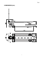
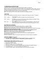
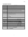
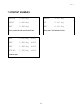
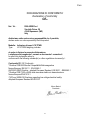
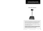
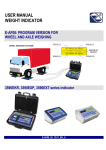
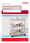
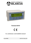
PALLET TRUCK SCALE
TPWN
USER MANUAL
TPWN_03_06.10_UK_U
TPWN
INDEX
INTRODUCTION ......................................................................................................... page 3
PALLET TRUCK SCALE
WARNINGS................................................................................................................. page 4
1 TECHNICAL SPECIFICATIONS .............................................................................. page 5
2 DIMENSIONS ........................................................................................................... page 6
3 OPERATING INSTRUCTIONS ................................................................................. page 7
4 REFERENCE DRAWINGS ....................................................................................... page 9
5 POWER SUPPLY & START UP............................................................................... page 10
WEIGHT INDICATOR
6 FRONT PANEL KEYS.............................................................................................. page 12
7 SYMBOLS ON LCD DISPLAY ................................................................................. page 13
8 BASIC FUNCTION ...................................................................................................page 14
8.1 ZERO SCALE....................................................................................................page 14
8.2 TARE OPERATIONS......................................................................................... page 14
8.3 AUTO SWITCH-OFF FUNCTION...................................................................... page 15
8.4 MULTIRANGE AND MULTIDIVISION FUNCTION ............................................ page 15
8.5 FUNCTIONING WITH REMOTE CONTROL ..................................................... page 15
8.6 PRINTING ......................................................................................................... page 16
8.7 REENABLING OF THE PRINTOUTS AND
INDICATOR FUNCTIONS ................................................................................ page 16
8.8 METRIC DATA VISUALISATION (inFO) ........................................................... page 16
8.9 DISPLAY WITH SENSITIVITY X 10 (VISS)
(TO BE USED IN TESTING DURING THE CALIBRATION) ............................. page 17
8.10 NET/GROSS SWITCHING .............................................................................. page 17
9 SELECTABLE FUNCTIONING MODES ..................................................................page 18
9.1 NORMAL (norM)................................................................................................ page 18
9.2 PEAK (PEAK) ....................................................................................................page 18
9.3 HOLD (HoLd).....................................................................................................page 18
9.4 TOTALISER (tot) ............................................................................................... page 18
10 INSTRUMENT MESSAGES ................................................................................... page 19
11 PRINTOUT EXAMPLES ......................................................................................... page 20
CE DECLARATION OF CONFORMITY ...................................................................... page 21
WARRANTY AND AUTHORISED SERVICE CENTER STAMP .................................page 22
2
TPWN
INTRODUCTION
This manual contains alla the instructions for use and all information necessary for the correct operation of the
weighing system.
In thanking you for the acquisition of this weight system, we want to call to your attention some aspects of this
manual:
• This booklet supplies useful instrucions for the correcr operarion and maintance of the weighing system to
which it refers; it is therefore necessary to pay the utmost attention to all the paragraphs which illustrate the
most simple and secure way to operate;
• This booklet must be considered an integral part of the weighing system and must included with the deed
of sale;
• Neither this publication, nor part of it, can be reproduced without written authorization on the part of the
manufacturing firm;
• All of the information reported herein is based on data avaiable at the moment of printing; the
manufacturing firm reserves the right to carry out modifications to its own products at any moment, without
notice and without any sanction. It is therefore suggested to always verify possible updates.
• Some functions written in the sections regarding the weight indicator might not be available, because these
depend on the type of weighing system that has been purchased.
PS: The person responsible for the use of the weight indicator must make sure that all of the safety
rules in force in the country of its use should be applied, to guarantee that the equipment is used in
conformity with the use for which it is destined and avoid any dangerous situation for the utilizer.
The manufacturing firm declines any responsability derivable from possible errors of wheighing.
RECYCLING INSTRUCTION
The crossed-out wheeled bin on the product means that at the product end of life, it must
be taken to separate collection or to the reseller when a new equivalent type of equipment
is purchased. The adequate differentiated refuse collection in having the product recycled,
helps to avoid possible negative effects on the environment and health and supports the
recycling of the materials of which the equipment is made. The unlawful disposal of the
product by the user will entail fines foreseen by the current regulations.
NOTE FOR THE USER:
Please take note that when the “ TECH.MAN.REF.” is mentioned, means that an advanced function is
being described (therefore for the technical personnel) which will be further explained in the
corresponding technical manual.
3
TPWN
PALLET TRUCK SCALE
!! WARNING !!
THIS PALLET TRUCK SCALE HAS BEEN DESIGNED TO ONLY WEIGH ON
PALLETS
1.
2.
3.
4.
5.
6.
7.
Never exceed maximum load, see the weight indicator’s label.
Do not use in an environment with any risk of explosion
Load only when forks are in the lowest position.
Check that the pallet truck scale is in good operating conditions.
!! CAUTION !! To get the best weighing results, lift up the forks about 5-10 cm.
Do not expose the weighing indicator to atmospheric agents ( rain, sun, etc. ).
Read and understand all instructions.
FIX THE LOAD ON THE PALLET, AS SHOWN IN THE DRAWING
4
TPWN
1 TECHNICAL SPECIFICATIONS
POWER SUPPLY
OPERATING TEMPERATURE
DISPLAY
KEYBOARD
TARE FUNCTION
AUTO POWER OFF
MAXIMUM LOAD
STRUCTURE
LOAD CELLS
LOAD CELL POWER SUPPLY
LOAD CELL CONNECTIONS
STEERING WHEELS
FORK’S ROLLS
Fitted with 9 V alkaline battery (not rechargeable)
From -10 to +40 ° C (14 to 104 ° F)
LCD display with 6 high contrast 25mm digits with indication of active
functions.
Waterproof and functional keypad.
Available on entire range
Adjustable from 1 to 30 minutes (may be disabled)
2000kg
Extra thick sheet-steel and oven fire painted interior construction.
4 1000-Ohm shear beam aluminium load cells.
5Vdc ± 5%, 120mA protection from short circuit.
4 wires (EXC+, EXC -, S+, S-).
∅ 200 mm vulkolan made
∅ 82 mm vulkolan made, double.
5
TPWN
2 DIMENSIONS (mm)
6
TPWN
3 OPERATING INSTRUCTIONS
A pallet truck scale is an electronic weighing system directly installed on a pallet truck.
Must be used on even solid surfaces and driven always in the normal position. Before loading, check the
maximum load allowed by the pallet truck scale in use, refer to instruction plate on the side of the pallet truck.
The rudder has a double function, direction control and hydraulic lifting.
N.B. Lift up or pull down ONLY when the pallet truck scale is in a standing still position.
CONTROLS
The lever on the right side of the rudder can be put in 3 positions, like it shows on the plate “Y” in figure B.
POS. 1 – centre =
TRANSPORT The rudder is completely free to allow driving control.
POS. 2 – down =
LIFT UP By moving the lever downward the lifting mechanism is activated. Pushing
down the rudder will cause the load to lift up.
POS. 3 – up
PULL DOWN By moving the lever upward the load will descend. When the lever is
quickly moved upward, a special valve controls the descending speed of the load.
=
MAINTENANCE WARNINGS
Before you perform any service, make sure the pallet truck is in a condition of safety.
Never discharge any residue without taking the necessary environmental precautions.
Only perform the service described in this manual. Maintenance and repair jobs not included in this manual
must be performed by authorised personnel only.
Serious injury could result from service or maintenance performed by unqualified personnel.
Never alter the safety level of the machine. Always use identical replacement parts.
Never remove or hide in anyway instruction plates and stickers.
The more intricate maintenace and/or the repair must be carried out by specialized personnel.
Do not modify the pallet truck.
Do not use inflammable cleaners. Do not use direct jets of water. Do not pour liquids on the indicator.
RUDDER ASSEMBLY (figure D)
1. Lock rudder ( 228 ) to hydraulic pump ( 200 ) with screws ( 27 ) that you can find in the box.
2. Lock chain ( 208 ) to lift down pedal ( 50 ). Rotate pedal to simplify the connection.
DESCENDING SPEED REGULATION (figure D)
1.
2.
3.
4.
5.
6.
Lift up forks to maximum height.
Set right lever to POS. 1 ( centre ).
Make sure the rudder ( 228 ) is in a vertical position.
Unscrew bolt ( 2 ) and turn clockwise the adjustable screw ( 48 ) until the forks start to descend.
Turn adjustable screw 1 ½ turn counter clockwise, then screw bolt ( 2 ).
You should be able to obtain a descending movement from every position of the rudder.
7
TPWN
OIL LEVEL (figure C)
Check oil level every 6 months. Only use hydraulic oil. No engine oil or brake oil.
Oil viscosity 30 Cst at 40°C . Quantity 0.3 lt.
With the fork in the lower position follow these steps:
1. Remove cover ( 204 ), o-ring ( 11 ) and cap ( 202 ).
2. If necessary add oil. Maximum filling level is 200mm below top of tank.
3. Turn on the pump to get air out of the hydraulic circuit.
4. Put cap ( 202 ), o-ring ( 11 ) and cover (204 ) back.
DAILY MAINTENANCE
To keep the pallet truck scale in good operating condition, the operator must perform daily these
checkpoints:
• Check overall conditions.
• Check weighing scale.
• Check printer ( if installed ).
• Check pump.
• Check rollers and wheels.
SCHEDULED MAINTENANCE
Maintenance performed by qualified personnel only.
Make sure to put the pallet truck scale on a flat and solid surface.
• Check that nothing is blocking the rollers.
• Grease rollers and wheels bearings.
• Grease control lever on rudder.
• Check oil every six months. Fill up if necessary with IP46 hydraulic oil.
N.B. If oil needs to be replaced, follow the necessary precaution and law requirements for the disposal of
the exhausted oil.
• Replace rollers and wheels when necessary.
For any questions or problems check with an Authorised service Centre.
8
TPWN
4 REFERENCE DRAWINGS
1170
120
C"
9
TPWN
D"
5
10
TPWN
5 POWER SUPPLY & START UP
The instruments are powered with a stabilised 9 Vdc tension supplied from a 9 V not rechargeable alkaline
battery (supplied).
TO TURN ON the instrument press the ON/OFF key until the turning on and release.
The display shows in sequence:
07.01
in which 07 indicates the instrument type, 01 indicates the metrological software version.
XX.YY.ZZ
is the installed software version.
LEGAL o hIrES if the instrument is APPROVED or NON APPROVED, respectively.
9.XXXXX
it’s the gravitational value (only with APPROVED instrument).
----advancement bar.
The indicator has an “auto zero at start-up” function: in other words it means that if at start-up a weight within
+/- 10% of the capacity is detected, it will be zeroed; if the weight is not within this tolerance, with a non
approved instrument the display shows the present weight after a few instants, while with an approved
instrument “Z - LoW” (weigh too low) or “Z - hiG” (weigh too high) is shown continuously on the display, until
the weight does not re-enter within this tolerance; the auto zero function at start-up may be disabled through
the PC Tool (TECH.MAN.REF.).
TO TURN OFF the instrument keep the ON/OFF key pressed until the “- OFF –“ message appears on the
display and release the key.
11
TPWN
WEIGHT INDICATOR
6 FRONT PANEL KEYS
The front panel is designed for quick but simple weighing applications. It consists of an LCD display with easy to
read digits, 25 mm in height and 25 symbols for indicating the status or the active function.
IR Interface (*)
ON/OFF key
- It turns the instrument on and off.
- Allows viewing the scale’s metric information: capacity, division, minimum weigh for
each configured range.
- In the numeric input phase, it allows to exit without saving the modifications.
ZERO/TARE key
- If pressed for an instant it carries out the semiautomatic tare.
- If pressed at length, it clears the displayed gross weight, if it is within +/- 2% of the total
capacity.
F1 key
- If pressed at length, it allows to enter a manual tare from the keyboard.
- In the numeric input phase, it increases the digit to be modified.
- It enables the selected function.
- In the totaliser mode, it accumulates the weight.
12
TPWN
F2 key
- In the numeric input phase, it serves to select the digit to be modified (blinking).
- It executes the printing of the weight data.
- In the totaliser mode, it prints the accumulated total.
(*) Only in the models which provide for it
7 SYMBOLS ON LCD DISPLAY
20
19
18
17
1
16
2
15
3
14
4
5
6
NUMBER
1
2
3
4
5
6
7
8
9
10
11
12
13
14
15
16
17
18
19
20
7
8
9
10
11
12
13
FUNCTION
Indicates that the weight detected on the weighing system is near zero, within the interval of –
1/4 ÷ +1/4 of the division.
Indicates that the weight is unstable.
Indicates that the displayed weight is a net weight.
Indicates that the displayed weight is a gross weight.
Indicates the battery charge level.
When viewing the metric information, it identifies the indicated capacity range.
When viewing the metric information, it identifies the indicated minimum weigh range.
When viewing the metric information, it identifies the indicated division range.
Indicates that a semiautomatic tare is active.
Indicates that a manual tare is active.
Indicates that the instrument is in the first weighing range.
Indicates that the instrument is in the second weighing range.
Indicates that the instrument is in the third weighing range.
Indicates the unit of measure in use (kilogram).
Indicates the unit of measure in use (pounds).
Indicates the unit of measure in use (tons).
This is shown around the specific digits during the visualisation x 10.
Indicates that a specific function of the indicator is active.
Indicates that the peak function is active
Indicates that the hold function is active
13
TPWN
8 BASIC FUNCTIONS
8.1 ZERO SCALE
By pressing a long the ZERO/TARE key, it is possible to zero a gross weight value which is within +/- 2% of
the capacity; after the zeroing, the display shows 0 weight and the relative pilot lights are turned on.
8.2 TARE OPERATIONS
SEMI-AUTOMATIC TARE
By pressing for an instant the ZERO/TARE key any weight value present on the display is tared: the display
shows “ tArE” , “ -tA” for an instant and then 0 (net weight); the pilot lights turn on.
In any case a new tare operation cancels and substitutes the previous one.
NOTE: The semiautomatic tare will be acquire only if the weight is AT LEAST A DIVISION, STABLE (instability
~ led off) and VALID (in other words, the OVERLOAD condition must not be created).
ENTERING THE MANUAL TARE FROM KEYBOARD
Press F1 for a few seconds: the display shows “tArE“ and then "000000". Enter the desired value using the
following keys:
F1
F2
ON/OFF
increases the blinking digit.
selects the digit to be modified (blinking); the scrolling of the digits takes place from left to
right.
if pressed for an instant it zeros the enable tare i(f present) and allows to return to weighing mode
Confirm with the ZERO/TARE key; the value will be subtracted from the weight present on the plate and the
relative pilot lights will turn on.
If the entered value is not a multiple of the scale’s minimum division, it will be rounded off.
In any case a new tare operation cancels and substitutes the preceding one.
CANCELLING A TARE
One can manually cancel the tare value in different ways:
- unload the scale and press the ZERO/TARE key.
- carry out the tares in deduction, partially unloading the scale and pressing TARE to zero the display.
- enter a manual tare equal to 0.
LIMITATION OF THE TARE FUNCTIONS
- With a non approved instrument, the tare operations are unlimited, in other words, these are always active.
- With approved instrument, it is possible to limit the tare functions, using the PC tool (TECH.MAN.REF.); the
tare operations will have the following specifications:
SCALE CAPACITY
< = 100kg
> 100kg
FUNCTIONING
All the tare functions are disabled
- The SEMIAUTOMATIC TARE value can not be modified with a
manual tare or from database.
- The manual tare or from database can be entered or modified
only with an UNLOADED scale.
14
TPWN
8.3 FUNCTION OF AUTOMATIC TURN-OFF
The scale is fitted of a programmable automatic turn-off function, which allows to save energy in case of not
using it temporarily; the automatic turn-off starts functioning when the scale is unloaded (gross weight = 0) for
the time (in minutes) programmed in MoFF step (TECH.MAN.REF.).
The values vary among:
00
DISABLED
01
1 minute
02
2 minutes
…
30
30 minutes
8.4 MULTIRANGE AND MULTIDIVISION FUNCTION
The multi range functioning allows to subdivide the scale capacity in two or three ranges, each which is up
to 3000 divisions, improving in this way the first range division in the dual range and the first two ranges in the
triple range.
For example it is possible to approve the weighing system with:
- A single range: 6 kg capacity and 2 g division (3000 div.).
- Dual range: 6 /3 kg capacity and 2/1 g division (3000 + 3000 div.).
- Triple range: 15 / 6 / 3 kg capacity and 5/2/1 g division (3000 + 3000 + 3000 div.).
NOTE: For the approval of the weighing system in dual and triple range the cell must have better technical
features in comparison to the cell used for the approval in a single range.
This functioning is indicated by the turning on of the symbol which identify the range in which one is working:
W1 first range, W2 second range, W3 third range (if configured); by passing to the W2 range, the second
range division is enabled; by passing to the W3 range, the third range division is enabled, at this point the W1
first scale division is restored only by passing the gross zero of the scale.
The multidivisional functioning is similar to multirange, but with the difference that a range division is
enabled as soon as one enters in its range interval (in other words without passing by the scale zero).
NOTE: The selection of the range number with multirange and multidivisional functioning is made during the
indicator calibration (TECH.MAN.REF.).
8.5 REMOTE CONTROL
If the model is provided for an infrared ray interface, with the remote control it is possible to remotely use
all the scale functions or just the semiautomatic tare. To choose which type of functioning, one has to use the
Pc Tool (TECH.MAN.REF.).
In the “multifunction” configuration, the remote control keys take on the following functions:
ZERO
It carries out the zero scale, and in the input phase it confirms the entered value.
TARE
If pressed for an instant it executes the semiautomatic tare; if pressed at length it
allows to enter the manual tare.
MODE
increments the blinking digit.
PRINT
selects the digit to be modified (blinking), from left to right.
15
TPWN
8.6 PRINTING
• In the normal, peak, hold functioning modes, by pressing the F2 key, one will have:
- GROSS weight
- TARE weight
- NET weight
NOTE: If the hold or peak function is active, the printed weights are always the “frozen” ones.
• In the totaliser functioning mode by pressing F2 one will have:
- NET weight or weigh number.
By pressing the F1 key one will have:
- Net weight total and total number of weighs.
NOTE: The print data is not modifiable.
Executing printouts with NON approved scales.
In order to print with non approved scales the following conditions must exist:
- the weight must be stable;
- the gross weight must be >= of a division;
- the printing is always active.
Legal for Trade scale printing.
In order to be able to print with a legal for trade scale the following conditions must exist:
− the weight must be stable;
− the net weight must be >= the minimum weight (minimum of 20 divisions).
− the printing is reactivated depending on the setting of a parameter through the PC Tool: passage by zero
of the NET weight or weight instability (see section 6.7 “REENABLING OF THE PRINTOUTS AND OF
THE INDICATOR FUNCTIONS”).
8.7 REENABLING THE PRINTOUTS AND THE INDICATOR FUNCTIONS
While using the indicator, it is possible to incur into the “rELoAd” message shown on the display; this means
that the printing or the function which one wants to carry out must be reenabled (in order to avoid unwanted
executions).
It is possible to set the reenabling in different ways: “passage by zero of the net weight”, or “weight instability”,
by using the PC Tool (TECH.MAN.REF.)
8.8 DISPLAY OF METRIC DATA (inFO)
The indicator is fitted with a function named “INFO”, thanks to which it is possible to view the configuration
metric data:
- First range capacity, first range minimum weigh, first range division.
- Second range capacity, second range minimum weigh, second range division.
- Third range capacity, third range minimum weigh, third range division.
NOTES:
- The minimum weigh corresponds to 20 net weight divisions.
- The data of the second and third range appear only if actually configured.
16
TPWN
To view the metric data:
- Keep the ON/OFF key pressed until the display shows “inFO”, and release.
- The capacity value of the first range will appear and the following data will automatically scroll in this
order:
Capacity 1° range ð Minimum weigh 1° range ð Division 1° range ð Capacity 2° range ð Minimum
weigh 2° range ð Division 2° range ð Capacity 3° range ð Minimum weigh 3° range ð Division 3°
range.
- The indicator automatically returns in the weighing mode.
8.9 DISPLAY WITH SENSITIVITY X 10 (TO BE USED IN TESTING DURING THE
CALIBRATION)
-
Press at length the F2 key; the display shows “H- 10”.
Press ZERO/TARE to confirm.
The scale division will be divided by 10 (the relative pilot lights will turn on). If one prints during the
visualisation x 10, the weight values will be printed with the normal sensitivity.
-
To disable the function, press at lenght the F2 key (the display shows “H- 10”).
Press ZERO/TARE to confirm.
TAKE NOTE: In case the instrument is LEGAL FOR TRADE, the sensitivity times 10 is displayed for five
seconds after which the instrument returns to standard weight displaying. Furthermore, in case of 5-key
instrument, this displaying is possible only with capacities over 100 kg (220 lb).
8.10 NET/GROSS SWITCH
If one sets a tare, it is in any case possible to view the gross weight on the display:
- Press at length the F2 key; the display shows “H- 10”.
- Press the F1 or F2 key; the display shows “GroSS”.
- Press ZERO/TARE to confirm: the display shows the gross weight (the relative pilot lights turn on).
-
To disable the funciton, press at length the F2 key (the display shows “H- 10”).
Press the F1 or F2 key, the display shows “GroSS”.
Press ZERO/TARE to confirm.
NOTE: If the instrument is APPROVED, when “MODE” is pressed, the visualisation of gross weight remains
for about five seconds; then the instrument automatically will display the net weight.
17
TPWN
9 SELECTABLE OPERATING MODES
Besides the standard weighing function with the tare subtraction, the indicator can carry out an additional
function of either HOLD, PEAK or TOTALIZER.
The functioning mode si set in the “ ModE” step of the set-up environment, TECH.MAN.REF.
9.1 NORMAL (norM)
Simple display functioning mode, with no function linked to the F1 key.
9.2 PEAK (PEAK)
Simple display functioning mode. It is possible to use the instrument to store the maximum detected weight
value during the weighing (PEAK), useful to measure, for example, the break load of the materials. By
pressing the F1 key the peak mode is activated; for an instant the “PEAK” message appears and the
maximum weight reached until that moment is displayed. To end the test and return to the displaying of the
weight on the scale, press again the F1 key (the display shows for an instant the message “norM”).
The weight value detected will be:
• The maximum before a fast weight drop (measurement of break load).
• The maximum detected persisting on the scale.
NOTE: If the weight goes into overload, the scale automatically returns into the “normal” weighing mode.
9.3 HOLD (HoLd)
Simple display functioning mode. By pressing the F1 key for an instant the message “HoLd” will appear, and
then the weight value on the scale will be frozen on the display. To return to standard displaying, press again
the F1 key (for an instant the message “norM” will appear and the weight returns to be the current one on the
scale).
9.4 TOTALIZER (tot)
Simple display functioning mode; every time one wants to accumulate and print the weight it is necessary to
press F2 (the message “SUMXXX” appears on the display, in which XXX is the number of the current weigh).
To avoid undesired accumulations, the F2 key is active just once; it reenables itself if the weight passes by net
zero or by unstability (otherwise the display shows “Reload”).
NOTE: The reenabling can be set by using the tool on the PC (TECH.MAN.REF.)
To view and print the accumulated total, press F1; the display shows, in sequence:
- “totXXX” in which XXX is the number of the total weighs.
- the net weight total, blinking.
To clear the accumulated total, press ZERO/TARE while the net weight total is viewed (the display shows
“totCLr”); press another key to not clear.
If the accumulated total is equal to 0 kg, the instrument avoids the request of zeroing the total.
NOTES
- The accumulated total is cancelled when the instrument is turned off.
- The maximum number of totalisations is 999, it is necessary to clear the total in order to continue.
18
TPWN
10 INSTRUMENT MESSAGES
MESSAGE
- ok Z - LoW
Z - hiG
P-LoW
P-hiG
_____
¯ ¯ ¯ ¯ ¯
rELoAd
n-StAb
- PCund100
T-No-Z
G-No-Z
LEGAL
oVr999
Err -10
Err -11
Err -12
Err -13
Err -14
Err -15
Err -16
Err -17
Err -18
Err -19
Err -20
Err -21
Err -30
no-PrG
DESCRIPTION
New scale zero acquired correctly
The weight is too low to acquire the scale zero.
The weight is too high for acquiring the scale zero.
The weight is too low in order to print or totalise.
The weight is too high in order to print or totalise.
Underload condition (weight under the gross zero minus the 16,6% of the capacity).
Overload condition (weight exceeds the capacity value plus 9 divisions).
Weight not passed by net 0 or by unstability.
Unstable weight.
Communication with PC under way.
Indicates that, with approved scale, the visualisation with sensitivity times 10 is not
allowed if the capacity is less than 100 kg.
The tare is not 0: it’s not possible to execute the manual tare (with limitation of the
active tare)
The gross weight is not 0: it’s not possible to execute the manual tare (with limitation
of the active tare)
Function not allowed with approved scale.
Once reached 999 totalisations one must clear the total in order to execute other
ones.
Invalid first calibration point; check the calibration (TECH.MAN.REF.).
Invalid first calibration point; check the calibration (TECH.MAN.REF.).
Invalid first calibration point; check the calibration (TECH.MAN.REF.).
Invalid first calibration point; check the calibration (TECH.MAN.REF.).
Invalid second calibration point; check the calibration (TECH.MAN.REF.).
Invalid second calibration point; check the calibration (TECH.MAN.REF.).
Invalid second calibration point; check the calibration (TECH.MAN.REF.).
Invalid second calibration point; check the calibration (TECH.MAN.REF.).
Invalid third calibration point; check the calibration (TECH.MAN.REF.).
Invalid third calibration point; check the calibration (TECH.MAN.REF.).
Invalid third calibration point; check the calibration (TECH.MAN.REF.).
Invalid third calibration point; check the calibration (TECH.MAN.REF.).
Invalid zero tracking value; with the tool on the PC check in the “FUNCTIONING
MODE / PRINTOUTS” mode (TECH.MAN.REF.).
The indicator has not been set correctly: check the capacity, division values and the
calibration (TECH.MAN.REF.).
19
TPWN
11 PRINTOUT EXAMPLES
GROSS
3.000 kg
GROSS
3.000 kg
TARE
2.400 kg
PT
2.400 kg
NET
0.600 kg
NET
0.600 kg
Norm, peak, hold with semiautomatic tare.
NET
0.600 kg
n001
NET
0.800 kg
n002
NET
1.000 kg
n003
TOTAL
1.000 kg
n003
Norm, peak, hold with manual tare
Totaliser Mode.
20
TPWN
DICHIARAZIONE DI CONFORMITA'
Declaration of conformity
CE06
Noi / We :
DINI ARGEO srl
Via della Fisica, 20
41040 Spezzano (MO)
Italy
dichiariamo sotto nostra unica responsabilità che il prodotto,
declare under our sole responsibility that the product
Modello: Indicatore di peso LCS-TPWN
Type:
LCS-TPWN weighing indicator
al quale si riferisce la presente dichiarazione,
è conforme alla/e seguente/i norma/e o documento/i normativo/i :
to which this declaration refers to,
conforms with the following standard(s) or other regulations document(s) :
Conformità CE / CE Conformity :
* Direttiva CEE 89/336 sulla Compatibilità Elettromagnetica
Norme Europee EN 55011 , EN 50082-1
89/336 EU EMC Directive adopted European Standard EN 55011 , EN50082-1
* Direttive CEE 73/23 e 93/68 sulla sicurezza elettrica in bassa tensione.
Norma Europea EN 61010-1
73/23 and 93/68 EU Directives regarding low voltage electrical safety.
Adopted European Standard EN 61010-1
Marco Bertoni
Presidente
21
TPWN
ONE YEAR WARRANTY
The ONE YEAR warranty period begins on the day the
instrument is delivered. It includes spare parts and labour
repair at no charge if the INSTRUMENT IS RETURNED
prepaid to the DEALER’S PLACE OF BUSINESS. Warranty
covers all defects NOT attributable to the Customer (such as
improper use) and NOT caused during transport.
If on site service is requested (or necessary), for any reason,
where the instrument is used, the Customer will pay for all of
the service technician’s costs: travel time and expenses plus
room and board (if any).
The Customer pays for the transport costs (both ways), if the
instrument is shipped to DEALER or manufacturer for repair.
The WARRANTY is VOIDED if any of the following occurs:
repairs or attempted repairs are made by unauthorised
personnel, connected to equipment installed by others, or is
incorrectly connected to the power supply, or instrument has
defects or damage due to carelessness or failure to follow
the guidelines in this instruction manual.
This warranty DOES NOT provide for any compensation for
losses or damages incurred by the Customer due to
complete or partial failure of instruments, even during the
warranty period.
AUTHORISED SERVICE CENTRE STAMP
22