1
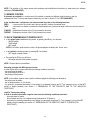
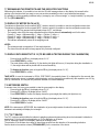
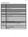
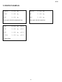
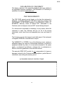
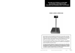
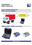
ELECTRONIC CRANE SCALES
“MCWL
”
SMART
USER MANUAL
MCWL_03_07.06_UK_U
MCWL
INDEX
INTRODUCTION............................................................................................................................................................page 2
WARNINGS ...................................................................................................................................................................page 2
SYMBOLS......................................................................................................................................................................page 3
CRANE SCALE
1 TECHNICAL SPECIFICATIONS.................................................................................................................................page 4
2 OPERATING INSTRUCTIONS ...................................................................................................................................page 4
3 DIMENSIONS..............................................................................................................................................................page 5
4 POWER SUPPLY AND START UP ............................................................................................................................page 6
WEIGHT INDICATOR
5 FRONT PANEL KEYS ................................................................................................................................................page 7
6 SYMBOLS ON LCD DISPLAY....................................................................................................................................page 8
7 BASIC FUNCTION......................................................................................................................................................page 8
7.1 ZERO SCALE...................................................................................................................................................... page 8
7.2 TARE OPERATIONS .......................................................................................................................................... page 8
7.3 AUTO SWITCH-OFF FUNCTION........................................................................................................................ page 9
7.4 MULTIRANGE AND MULTIDIVISION FUNCTION.............................................................................................. page 9
7.5 FUNCTIONING WITH REMOTE CONTROL..................................................................................................... page 10
7.6 DATA TRANSMISSION TO PRINTER OR PC.................................................................................................. page 10
7.7 REENABLING OF THE PRINTOUTS AND INDICATOR FUNCTIONS ............................................................ page 11
7.8 METRIC DATA VISUALISATION (inFO) ........................................................................................................... page 11
7.9 DISPLAY WITH SENSITIVITY X 10 (VISS) (TO BE USED IN TESTING DURING THE CALIBRATION)......... page 11
7.10 NET/GROSS SWITCHING.............................................................................................................................. page 11
7.11 TILT DEVICE................................................................................................................................................... page 11
7.12 LOW BATTERY WARNING ............................................................................................................................ page 12
8 SELECTABLE FUNCTIONING MODES...................................................................................................................page 12
8.1 NORMAL (norM) ............................................................................................................................................... page 12
8.2 PEAK (PEAK).................................................................................................................................................... page 12
8.3 HOLD (HoLd) .................................................................................................................................................... page 12
8.4 TOTALISER (tot) ............................................................................................................................................... page 12
9 INSTRUMENT MESSAGES......................................................................................................................................page 13
10 PRINTOUT EXAMPLES .........................................................................................................................................page 14
CE DECLARATION OF CONFORMITY ......................................................................................................................page 15
WARRANTY AND AUTHORISED SERVICE CENTER STAMP .................................................................................page 15
1
MCWL
INTRODUCTION
This manual contains alla the instructions for use and all information necessary for the correct operation of the weighing
system.
In thanking you for the acquisition of this weight system, we want to call to your attention some aspects of this manual:
· This booklet supplies useful instrucions for the correcr operarion and maintance of the weighing system to which it
refers; it is therefore necessary to pay the utmost attention to all the paragraphs which illustrate the most simple and
secure way to operate;
· This booklet must be considered an integral part of the weighing system and must included with the deed of sale;
· Neither this publication, nor part of it, can be reproduced without written authorization on the part of the manufacturing
firm;
· All of the information reported herein is based on data avaiable at the moment of printing; the manufacturing firm
reserves the right to carry out modifications to its own products at any moment, without notice and without any sanction.
It is therefore suggested to always verify possible updates.
· Some functions written in the sections regarding the weight indicator might not be available, because these depend on
the type of weighing system that has been purchased.
PS: The person responsible for the use of the weight indicator must make sure that all of the safety rules in force
in the country of its use should be applied, to guarantee that the equipment is used in conformity with the use for
which it is destined and avoid any dangerous situation for the utilizer.
The manufacturing firm declines any responsability derivable from possible errors of wheighing.
WARNING
Any attempt to repair or alter the unit can expose the user to the danger of electric shock and it will void our warranty. This
instrument is covered under warranty provided that IT HAS NOT BEEN OPENED BY THE USER for any reason.
Organizational measures
· Only trained and instructed persons may operate the appliance.
· Make sure that the instruction manual is always available on the installation site of the crane.
· Have installation, commissioning, maintenance and repairs carried out by specially trained personnel
only.
· Only use original replacement parts.
· All the connections of the indicator have to be made respecting the rules applicable in the zone and in
the installing environment.
Intended use
· Use the crane scale exclusively for lifting and weighing freely moveable loads and for tension
measurements.
· Movable loads which can cause torque stresses must be hanged with flexible or turnable constraints.
· DO NOT exceed the rated load capacity of the crane, crane scale or any load bearing item attached to
the crane scale.
· DO NOT trasport persons.
· DO NOT tear, loose, pull or drag loads.
· Changes or modifications to the crane scale or the crane are NOT permitted.
· DO NOT pour liquids on the indicator.
· DO NOT use solvents to clean the indicator.
2
MCWL
· DO NOT expose instrument to either direct sun light or any heat sources.
· DO NOT expose to heavy magnetic or electric fields.
· DO NOT not install in an environment with any risk of explosion
Safety conscious working methods
· Never walk or stand under hanging loads.
· Only position the crane so that the load is lifted vertically.
· Wear personal safety equipment (helmet, safety gloves) when working with the crane and crane scale.
· Position the load without causing knocks.
· Do use hardware that creates single point attachments and allows the scale freedom of alignment.
· DO NOT use oversize interface hardware which restricts single point loading.
· DO NOT use multiple attachments.
· DO NOT push or pull the load or the loaded scale.
· Read carefully & apply what described in the POWER SUPPLY & START-UP section.
SYMBOLS
Please find below the symbols used:
- in the manual to recall the attention of the reader.
- on the instrument to recall the attention of the user.
Warning! This operation must be performed only by qualified personal.
Conforms to the standards of the European Union.
Identifies the Class Of Precision defined by the OIML to represent 3000 divisions
“ TECH.MAN.REF.” means that an advanced function is being described (therefore for the technical personnel) which
will be further explained in the corresponding technical manual.
The crossed-out wheeled bin on the product means that at the product end of life, it must be taken to
separate collection or to the reseller when a new equivalent type of equipment is purchased. The
adequate differentiated refuse collection in having the product recycled, helps to avoid possible
negative effects on the environment and health and supports the recycling of the materials of which the
equipment is made. The unlawful disposal of the product by the user will entail fines foreseen by the
current regulations.
It is forbidden to halt or transit under suspended load.
3
MCWL
CRANE SCALE
1 TECHNICAL SPECIFICATIONS
LOAD CELL
POWER SUPPLY
REMOTE CONTROL
DISPLAY
STATUS INDICATORS
KEYBOARD
AUTO POWER OFF
OPERATING TEMPERATURE
CASE
Strain gauge based with high accuracy and repeatability.
9 V alkaline internal battery easy to replace. About 35-hour operating time.
fitted; it provides a maximum range of 8 m, configurable to operate tare function only
or as 4 keys remote keyboard.
LCD, character height 25 millimeters
20 multifunction symbols on the LCD display
Water resistant key polycarbonate membrane with tactile feedback.
Adjustable from 1 to 30 minutes of no use, disinsertable.
From – 10 to +40° C
Oven fired, painted.
2 BASIC OPERATING INSTRUCTIONS
1) Suspend the instrument from the crane it will be used on and press push-button ON/OFF for a few seconds: all
segments on the display will light for a few seconds as the crane scale conducts a lamp and other self-tests.
2) After the self-tests, press button for a few seconds marked ZERO/TARE. Especially important if the display shows a
non-zero value without a load on the scale.
3) If any accessories have been applied to the crane scale (connection rings, chains, hooks etc.) it is necessary to press
the ZERO/TARE key (pressed for an instant) or by using the remote control’s TARE button.
NOTES:
- The "TARE" key can be used with any weight applied in the range of its capacity.
- If slings are used to handle the load, make sure that the load is properly balanced and that the slings are positioned
properly.
4) When the display indicates " 0 ", the instrument is ready for use.
5) Start lifting the load slowly.
4
MCWL
3 DIMENSIONS (in mm)
C
E
D
B
F
MCWL600 / MCWLT6 / MCWLT1M / MCWLT5M
E
D
C
F
B
MCWLT10
MCWL600
MCWLT1M
MCWLT6
MCWLT10
MCWLT5M
A
B
C
D
E
F
G
H
I
184
171
49
24
43
125
94
291
144
214
171
59
33
58
125
94
353
158
241
171
64
46
75
125
94
419
171
5
MCWL
4 POWER SUPPLY & START UP
The instruments are normally powered with a stabilised 9 Vdc voltage supplied by a non rechargeable alkaline battery.
TO TURN ON the instrument press the ON/OFF key until the turning on and release.
The display shows in sequence:
- on 07.01
in which 07 indicates the instrument type, 01 indicates the metrological software version.
XX.YY.ZZ
is the installed software version.
LEGAL or hIrES if the instrument is APPROVED or NON APPROVED, respectively.
9.XXXXX
it’s the gravitational value (only with APPROVED instrument).
----advancement bar.
The indicator has an “auto zero at start-up” function: in other words it means that if at start-up a weight within +/- 10% of the
capacity is detected, it will be zeroed; if the weight is not within this tolerance, with a non approved instrument the display
shows the present weight after a few instants, while with an approved instrument “Z - LoW” (weigh too low) or “Z - hiG”
(weigh too high) is shown continuously on the display, until the weight does not re-enter within this tolerance; the auto zero
function at start-up may be disabled through the PC Tool (TECH.MAN.REF.).
TO TURN OFF the instrument keep the ON/OFF key pressed until the “- oFF – “ message appears on the display and
release the key.
6
MCWL
WEIGHT INDICATOR
5 FRONT PANEL KEYS
The front panel is designed for quick but simple weighing applications. It consists of an LCD display with easy to read digits, 25
mm in height and 20 symbols for indicating the status or the active function.
IR Interface
ON/OFF key
- It turns the instrument on and off.
- Allows viewing the scale’s metric information: capacity, division, minimum weigh for
each configured range.
ZERO/TARE key
- If pressed for an instant it carries out the semiautomatic tare.
- If pressed at length, it clears the displayed gross weight, if it is within +/- 2% of the total
capacity.
F1 key
- If pressed at length, it allows to enter a manual tare from the keyboard.
- In the numeric input phase, it increases the digit to be modified.
- It enables the selected function.
- In the totaliser mode, it prints the accumulated total
F2 key
- In the numeric input phase, it serves to select the digit to be modified (blinking).
- It executes the printing of the weight data.
- In the totaliser mode, it accumulates the weight.
7
MCWL
6 SYMBOLS ON LCD DISPLAY
20
19
18
17
1
16
2
15
3
14
4
5
6
NUMBER
1
2
3
4
5
6
7
8
9
10
11
12
13
14
15
16
17
18
19
20
7
8
9
10
11
12
13
FUNCTION
The weight detected on the weighing system is near zero, within the interval of – 1/4 ÷ +1/4 of the
division.
The weight is unstable.
The displayed weight is a net weight.
The displayed weight is a gross weight.
Indicates the battery charge level.
When viewing the metric information, it identifies the indicated capacity range.
When viewing the metric information, it identifies the indicated minimum weigh range.
When viewing the metric information, it identifies the indicated division range.
A semiautomatic tare is active.
A manual tare is active.
The instrument is in the first weighing range.
The instrument is in the second weighing range.
The instrument is in the third weighing range.
Indicates the unit of measure in use (kilogram or gram).
Indicates the unit of measure in use (pounds).
Indicates the unit of measure in use (tons).
This is shown around the specific digits during the visualisation x 10.
A specific function of the indicator is active.
The peak function is active
The hold function is active
7 BASIC FUNCTIONS
7.1 ZERO SCALE
By pressing a long the ZERO/TARE key, it is possible to zero a gross weight value which is within +/- 2% of the capacity;
after the zeroing, the display shows 0 and the relative pilot lights are turned on.
7.2 TARE OPERATIONS
SEMI-AUTOMATIC TARE
By pressing for an instant the ZERO/TARE key any weight value present on the display is tared: the display shows “ tArE” ,
“ -tA” for an instant and then 0 (net weight); the pilot lights turn on.
NOTE: The semiautomatic tare will be acquire only if the weight is AT LEAST A DIVISION, STABLE (instability ~ led off)
and VALID (in other words, the OVERLOAD condition must not be created).
8
MCWL
ENTERING THE MANUAL TARE FROM KEYBOARD
Press F1 for a few seconds: the display shows “tArE“ and then "000000". Enter the desired value using the following keys:
F1
F2
ON/OFF
increases the blinking digit.
selects the digit to be modified (blinking); the scrolling of the digits takes place from left to
right.
if pressed for an instant it zeros the enable tare (if present) and allows to return to weighing mode
Confirm with the ZERO/TARE key; the value will be subtracted from the gross weight and the relative pilot lights will turn on.
If the entered value is not a multiple of the scale’s minimum division, it will be rounded off.
CANCELLING A TARE
One can manually cancel the tare value in different ways:
- unload the scale and press the ZERO/TARE key.
- carry out the tares in deduction, partially unloading the scale and pressing TARE to zero the display.
- enter a manual tare equal to 0.
LIMITATION OF THE TARE FUNCTIONS
With approved instrument, it is possible to limit the tare functions, using the PC tool (TECH.MAN.REF.); the tare operations
will have the following specifications:
SCALE CAPACITY
< = 100kg
> 100kg
FUNCTIONING
All the tare functions are disabled
- The SEMIAUTOMATIC TARE value can not be modified with a
manual tare or from database.
- The manual tare can be entered or modified only with an
UNLOADED scale.
7.3 FUNCTION OF AUTOMATIC TURN-OFF
The scale is fitted of a programmable automatic turn-off function, which allows to save energy in case of not using it
temporarily; the automatic turn-off starts functioning when the scale is unloaded (gross weight = 0) for the time (in minutes)
programmed in MoFF step (TECH.MAN.REF.).
The values vary among:
00 DISABLED
01 1 minute
02 2 minutes
…
30
30 minutes
7.4 MULTIRANGE AND MULTIDIVISION FUNCTION
The multi range functioning allows to subdivide the scale capacity in two or three ranges, each which is up to 3000
divisions, improving in this way the first range division in the dual range and the first two ranges in the triple range.
For example it is possible to approve the weighing system with:
- A single range: 6 kg capacity and 2 g division (3000 div.).
- Dual range: 6 /3 kg capacity and 2/1 g division (3000 + 3000 div.).
- Triple range: 15 / 6 / 3 kg capacity and 5/2/1 g division (3000 + 3000 + 3000 div.).
NOTE: For the approval of the weighing system in dual and triple range the cell must have better technical features in
comparison to the cell used for the approval in a single range.
This functioning is indicated by the turning on of the symbol which identify the range in which one is working: W1 first range,
W2 second range, W3 third range; by passing to the W2 range, the second range division is enabled; by passing to the W3
range, the third range division is enabled, at this point the W1 first scale division is restored only by passing the gross
zero of the scale.
The multidivisional functioning is similar to multirange, but with the difference that a range division is enabled as soon as
one enters in its range interval (in other words without passing by the scale zero).
9
MCWL
NOTE: The selection of the range number with multirange and multidivisional functioning is made during the indicator
calibration (TECH.MAN.REF.).
7.5 REMOTE CONTROL
If the model is provided for a remote control it is possible to remotely use different scale functions or just the
semiautomatic tare. To choose which type of functioning, one has to use the Pc Tool (TECH.MAN.REF.).
In the “ multifunction” configuration, the remote control keys take on the following functions:
ZERO
It carries out the zero scale, and in the input phase it confirms the entered value.
TARE
If pressed for an instant it executes the semiautomatic tare; if pressed at length it allows to enter the manual
tare.
F1/MODE Emulates the function of the F1 key pressed for an instant.
F2/PRINT Emulates the function of the F2 key pressed for an instant.
7.6 DATA TRANSMISSION TO PRINTER OR PC
· In the normal, peak, hold functioning modes, by pressing the F2 key, one will have:
- GROSS weight
- TARE weight
- NET weight
NOTE: If the hold or peak function is active, the printed weights are always the “frozen” ones.
· In the totaliser functioning mode by pressing F2 one will have:
- NET weight or weigh number.
· By pressing the F1 key one will have:
- Net weight total and total number of weighs.
NOTE: The print data is not modifiable.
Executing printouts with NON approved scales.
In order to print with non approved scales the following conditions must exist:
- the weight must be stable;
- the gross weight must be ≥ 0;
- the printing is always active.
NOTE: In the totaliser mode in order to print the totalised weight the following must take place:
- the weight must be stable;
- the net weight must be >= of a division;
- the printing is reactivated depending on the setting of a parameter through the PC Tool: passage by zero of the NET
weight or weight instability (see section 7.7 “REENABLING OF THE PRINTOUTS AND OF THE INDICATOR
FUNCTIONS”).
Legal for Trade scale printing.
In order to be able to print with a legal for trade scale the following conditions must exist:
- the weight must be stable;
- the net weight must be >= the minimum weight (minimum of 20 divisions).
- the printing is reactivated depending on the setting of a parameter through the PC Tool: passage by zero of the NET
weight or weight instability (see section 6.7 “REENABLING OF THE PRINTOUTS AND OF THE INDICATOR
FUNCTIONS”).
10
MCWL
7.7 REENABLING THE PRINTOUTS AND THE INDICATOR FUNCTIONS
While using the indicator, it is possible to incur into the “rELoAd” message shown on the display; this means that the
printing or the function which one wants to carry out must be reenabled (in order to avoid unwanted executions).
It is possible to set the reenabling in different ways: “passage by zero of the net weight”, or “weight instability”, by using the
PC Tool (TECH.MAN.REF.).
7.8 DISPLAY OF METRIC DATA (inFO)
The indicator is fitted with a function named “INFO”, thanks to which it is possible to view the configuration metric data:
The indicator is fitted with a function named “INFO”, thanks to which it is possible to view the configuration metric data:
- Keep the ON/OFF key pressed until the display shows “inFO”, and release.
- The capacity value of the first range will appear and the following data will automatically scroll in this order:
Capacity 1° range ð Minimum weigh 1° range ð Division 1° range ð
Capacity 2° range ð Minimum weigh 2° range ð Division 2° range ð
Capacity 3° range ð Minimum weigh 3° range ð Division 3° range.
- The indicator automatically returns in the weighing mode.
NOTES:
- The minimum weigh corresponds to 20 net weight divisions.
- The data of the second and third range appear only if actually configured.
7.9 DISPLAY WITH SENSITIVITY X 10 (TO BE USED IN TESTING DURING THE CALIBRATION)
-
Press at length the F2 key; the display shows “H- 10”.
Press ZERO/TARE to confirm.
The scale division will be divided by 10 (the relative pilot lights will turn on). If one prints during the visualisation x
10, the weight values will be printed with the normal sensitivity.
-
To disable the function, press at lenght the F2 key (the display shows “H- 10”).
Press ZERO/TARE to confirm.
TAKE NOTE: In case the instrument is LEGAL FOR TRADE, the sensitivity times 10 is displayed for five seconds after
which the instrument returns to standard weight displaying, and this displaying is possible only with capacities over 100 kg
(220 lb). Furthermore, one can print only when the indicator is in normal sensitivity.
7.10 NET/GROSS SWITCH
If one sets a tare, it is in any case possible to view the gross weight on the display:
- Press at length the F2 key; the display shows “H- 10”.
- Press the F1 or F2 key; the display shows “GroSS”.
- Press ZERO/TARE to confirm: the display shows the gross weight (the relative pilot lights turn on).
-
To disable the funciton, press at length the F2 key (the display shows “H- 10”).
Press the F1 or F2 key, the display shows “GroSS”.
Press ZERO/TARE to confirm.
NOTE: If the instrument is APPROVED, the visualisation of gross weight remains for about five seconds; then the
instrument automatically will display the net weight.
7.11 "TILT" DEVICE
The TILT is a device which inhibits the indicator’s weighing system and starts working when the instrument’s inclination is
greater than 2% for the pallet truck application or 5% for application on lift trucks.
The “tilt” message is shown on the display, alternate to the weight value.
The activation of the tilt alarm has a delay of about three seconds from the detection of the exceeding inclination.
See the electrical connection scheme (TECH.MAN.REF.) for the connection of the device.
11
MCWL
7.12 LOW BATTERY WARNING
The indicator is able to recognize whether it is powered from the mains or through a battery.
The charge level is shown in the weighing phase by the battery symbol:
-
: battery is charged.
-
:battery is discharged: change the battery.
NOTES:
- The instrument automatically turns off when the voltage goes below the minimum level: the "Lo-bAt " message appears on
the display for a few seconds.
8 SELECTABLE OPERATING MODES
Besides the standard weighing function with the tare subtraction, the indicator can carry out an additional function of either
HOLD, PEAK or TOTALIZER.
The functioning mode si set in the “ ModE” step of the set-up environment, TECH.MAN.REF.
8.1 NORMAL (norM)
Simple display functioning mode, with no function linked to the F1 key.
8.2 PEAK (PEAK)
It is possible to use the instrument to store the maximum detected weight value during the weighing (PEAK), useful to
measure, for example, the break load of the materials. By pressing the F1 key the peak mode is activated; for an instant the
“PEAK” message appears and the maximum weight reached until that moment is displayed. To end the test and return to
the displaying of the weight on the scale, press again the F1 key (the display shows for an instant the message “norM”).
NOTE: If the weight goes into overload, the scale automatically returns into the “normal” weighing mode.
8.3 HOLD (HoLd)
By pressing the F1 key for an instant the message “HoLd” will appear, and then the weight value on the scale will be frozen
on the display. To return to standard displaying, press again the F1 key (for an instant the message “norM” will appear and
the weight returns to be the current one on the scale).
8.4 TOTALIZER (tot)
Every time one wants to accumulate and print the weight it is necessary to press F2 (the message “SUMXXX” appears on
the display, in which XXX is the number of the current weigh).
To avoid undesired accumulations, the F2 key is active just once; it reenables itself if the weight passes by net zero or by
unstability (otherwise the display shows “Reload”).
NOTE: The reenabling can be set by using the tool on the PC (TECH.MAN.REF.)
To view and print the accumulated total, press F1; the display shows, in sequence:
- “totXXX” in which XXX is the number of the total weighs.
- the net weight total, blinking.
To clear the accumulated total, press ZERO/TARE while the net weight total is viewed (the display shows “totCLr”); press
another key to not clear. If the accumulated total is equal to 0 kg, the instrument avoids the request of zeroing the total.
NOTES
- The accumulated total is cancelled when the instrument is turned off.
- The maximum number of totalisations is 999, it is necessary to clear the total in order to continue: by pressing the
F1 key, the "oVr999" message appears.
12
MCWL
9 INSTRUMENT MESSAGES
MESSAGE
- ok Z - LoW
Z - hiG
P-LoW
P-hiG
d-SALE
ubAL-1
ubAL-2
ubAL-3
ubAL-4
_____
¯ ¯ ¯ ¯ ¯
rELoAd
no-Stb
- PCund100
T-No-Z
G-No-Z
t-MAn
t-rEGr
oVr-r
LEGAL
oVr999
Err -10, Err -11,
Err -12, Err -13
Err -14, Err -15,
Err -16, Err -17
Err -18, Err -19,
Err -20, Err -21
Err -30
no-PrG
DESCRIPTION
New scale zero acquired correctly
The weight is too low to acquire the scale zero.
The weight is too high for acquiring the scale zero.
The weight is too low in order to print or totalise.
The weight is too high in order to print or totalise.
It shows that, with an approved scale, the tare operation is not permitted unless the capacity is
equal or less than 100 kg.
Load unbalanced on channel 1.
Load unbalanced on channel 2.
Load unbalanced on channel 3.
Load unbalanced on channel 4.
Underload condition (weight under the gross zero minus the 16,6% of the capacity).
Overload condition (weight exceeds the capacity value plus 9 divisions).
Weight not passed by net 0 or by unstability.
Unstable weight.
Communication with PC under way.
Indicates that, with approved scale, the visualisation with sensitivity times 10 is not allowed if
the capacity is less than 100 kg.
The tare is not 0: it’s not possible to execute the manual tare (with limitation of the active tare)
The gross weight is not 0: it’s not possible to execute the manual tare (with limitation of the
active tare)
Active manual tare: it’s not possible to execute the semiautomatic tare (with limitation of the
active tare)
Tare in subtraction: it’s not possible to execute the semiautomatic tare (with limitation of the
active tare)
Value greater than the scale capacity: it’s not possible to carry out the tare.
Function not allowed with approved scale.
Once reached 999 totalisations one must clear the total in order to execute other ones.
Invalid first calibration point; check the calibration (TECH.MAN.REF.).
Invalid second calibration point; check the calibration (TECH.MAN.REF.).
Invalid third calibration point; check the calibration (TECH.MAN.REF.).
Invalid zero tracking value; with the tool on the PC check in the “FUNCTIONING MODE /
PRINTOUTS” mode (TECH.MAN.REF.).
The indicator has not been set correctly: check the capacity, division values and the calibration
(TECH.MAN.REF.).
13
MCWL
10 PRINTOUT EXAMPLES
GROSS
3.000 kg
GROSS
3.000 kg
TARE
2.400 kg
PT
2.400 kg
NET
0.600 kg
NET
0.600 kg
Norm, peak, hold with semiautomatic tare.
NET
0.600 kg
n001
NET
0.800 kg
n002
NET
1.000 kg
n003
TOTAL
1.000 kg
n003
Norm, peak, hold with manual tare
Totaliser Mode.
14
MCWL
DECLARATION OF CONFORMITY
This device conforms to the essential standards and norms relative to
the applicable European regulations. The Declaration of Conformity is
available in the web site www.vetek.com
ONE YEAR WARRANTY
The ONE YEAR warranty period begins on the day the instrument is
delivered. It includes spare parts and labour repair at no charge if the
INSTRUMENT IS RETURNED prepaid to the DEALER’S PLACE OF
BUSINESS. Warranty covers all defects NOT attributable to the
Customer (such as improper use) and NOT caused during transport.
If on site service is requested (or necessary), for any reason, where the
instrument is used, the Customer will pay for all of the service
technician’s costs: travel time and expenses plus room and board (if
any).
The Customer pays for the transport costs (both ways), if the instrument
is shipped to DEALER or manufacturer for repair.
The WARRANTY is VOIDED if any of the following occurs: repairs or
attempted repairs are made by unauthorised personnel, connected to
equipment installed by others, or is incorrectly connected to the power
supply, or instrument has defects or damage due to carelessness or
failure to follow the guidelines in this instruction manual.
This warranty DOES NOT provide for any compensation for losses or
damages incurred by the Customer due to complete or partial failure of
instruments, even during the warranty period.
AUTHORIS ED SE RVICE CENTR E STAMP
15