1
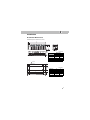
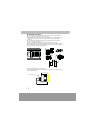
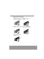
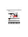
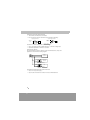
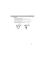
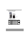
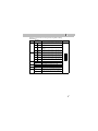
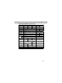
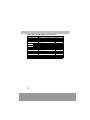
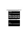
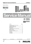
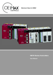
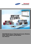
Instruction Manual
LX700
Important User Information ............................................................. 3
Safety Instructions ............................................................................ 4
Installation ......................................................................................... 5
Installation Dimensions ...................................................................................
Installation Location.........................................................................................
Installation Environment and Precaution ......................................................
Mounting/Dismounting Module .....................................................................
5
6
7
8
Wiring................................................................................................. 9
Power Supply Module Wiring ..................................................................... 9
Grounding....................................................................................................... 11
Operating Condition Setting .......................................................... 12
LX-CPU700p Processor Module.................................................................... 12
Input/Output Modules..................................................................... 14
Digital Input Module Specifications ..........................................................
Digital Relay Output Module Specifications .............................................
Digital Transistor Output Module Specifications......................................
Digital SSR Output Module Specifications ...............................................
15
16
17
17
Input/Output Module Wiring Diagrams......................................... 18
LX-X16D Wiring Diagram ..............................................................................
LX-X32D Wiring Diagram ..............................................................................
LX-X64D Wiring Diagram ..............................................................................
LX-X16A110 and LX-X16A220 Wiring Diagram ..........................................
LX-Y16R and LX-Y16RV Wiring Diagram .....................................................
LX-Y32RV Wiring Diagram ............................................................................
LX-Y16T Wiring Diagram...............................................................................
LX-Y32T Wiring Diagram...............................................................................
LX-Y16SSR Wiring Diagram..........................................................................
18
18
19
19
20
20
21
21
22
Important User Information
Solid state equipment has operational characteristics differing from those of
electromechanical equipment. Because of this difference, and also because of the
wide variety of uses for solid state equipment, all persons responsible for applying
this equipment must satisfy themselves that each intended application of this
equipment is acceptable.
In no event will L&T be responsible or liable for indirect or consequential damages
resulting from the use or application of this equipment.
The examples and diagrams in this manual are included solely for illustrative
purposes. Because of the many variables and requirements associated with any
particular installation, L&T cannot assume responsibility or liability for actual use
based on the examples and diagrams.
No patent liability is assumed by L&T with respect to use of information, circuits,
equipment, or software described in this manual.
Reproduction of the contents of this manual, in whole or in part, without written
permission of L&T is prohibited.
Throughout this manual we use the following symbols to make you aware of safety
considerations.
WARNING
IMPORTANT
ATTENTION
Identifies information about practices or circumstances which may
lead to serious personal injury or death, property damage, or
economic loss.
Identifies information that is critical for successful application and
understanding of the product.
Identifies information about practices or circumstances that can
lead to minor personal injury, property damage, economic loss, or
product malfunction. However, depending on the situation, failure
to follow the directions accompanying this symbol may also lead to
serious consequences.
3
4
4
Safety Instructions
Please read this manual and the related documentation thoroughly and familiarize
yourself with product information, safety instructions and other directions before
installing, operating, performing inspection and preventive maintenance.
Please be aware that the instructions are marked with either a warning symbol or
attention symbol.
WARNING
ATTENTION
4
4
• If this product is used in a situation that may cause personal
injury and/or significant product damage, implement safe
measures such as use of fault-safe equipment.
• Be sure to cutoff outer power source while wiring, maintenance,
and cleaning. Do not touch terminals when electric current is
flowing. Otherwise it may cause an electric shock.
• Do not use this product under any conditions exposed to
explosive gases. It may cause an explosion.
• Use the product under the allowed conditions directed in
product specifications and be cautious to keep away extraneous
materials from entering the product during installation.
– Do not expose to high temperature, high humidity, dense dust,
salinity, mineral particles, corrosive gas, inflammable gas,
solvent, abrasive materials, and direct sunlight.
– Keep away from vibrations, and contacts of other objects. It is
the cause of damage, malfunction, or aging.
• Fasten the terminal screws tightly to ensure that the cable
connection is secure. Incorrect cable connection may cause
overheating and product malfunction.
• Make sure to use an external device when configuring the
protective circuit breakers for emergencies or interlock circuits.
• Operate the product under the allowed conditions directed in
product specifications. Incorrect conditions can cause abnormal
heat dissipation or product malfunction.
• Do not dissemble or modify the product, or it may cause
malfunctions. Use the service centers for product repairs.
• Do not touch the terminals when the power is on. It may cause
an electric shock.
• Only use the product for functions explicitly specified in the
product and the manual.
• Abide by the industrial waste disposal standard when disposing
the product.
5
5
Installation
Installation Dimensions
LX700 PLC System Dimensions (mm)
A
B
Y16T
Y16T
TR OUT
Y16T
TR OUT
Y16T
TR OUT
Y32T
TR OUT
DC IN
X32D
TR OUT
X64D
DC IN
CP U
X64D
DC IN
CPU750B
115.5 118.5
Progrmmable
Controller
OPEN
unit (mm)
111.0
Slot Type
Dimensions
A
B
3-slot type
205.0
184.0
5-slot type
276.0
254.0
8-slot type
381.0
360.0
10-slot type
452.0
430.0
12-slot type
522.0
501.0
Slot Type
P
L
3-slot type
205.0
153.8
5-slot type
276.0
224.2
8-slot type
381.0
329.8
10-slot type
452.0
400.2
12-slot type
522.0
470.6
5.0 * 4
27.5
unit (mm)
81.0
22.5
L
P
7.0
5
Installation Location
OPEN
Controller
19
18
20
POWER
20
17
16
19
18
4
3
15
14
6
5
11
10
13
12
2
1
15
14
4
3
6
5
8
7
9
11
10
13
12
Programmable
Be sure to maintain a sufficient distance from wiring ducts, and other machines
below and above the module for proper ventilation.
Do not install the modules stacked up or horizontally. Doing so will prevent proper
cooling of the module and cause overheating inside the PLC (programmable
controller).
Do not install the module above devices which generate heat such as heaters,
transistors or large scale resistors.
In order to eliminate any effects from noise emission, power wires and
electromagnetic devices should be kept at least 100 mm away from the surfaces of
the module. When installing the module behind the doors of the operation panel, be
especially careful to maintain these distances.
RS232C
PROG
RMT
RUN
TEST
INIT
17
16
2
1
8
7
9
Duct
4039
1 2
40 39
2
1
40 39
2
12
20
19
18
11
10
17
16
15
9
8
7
14
13
6
5
4
3
2
1
20
12
11
10
9
8
7
6
5
19
18
4
17
3
2
14
13
RS232C
POWER
16
15
PROG
RMT
INIT
RUN
TEST
INIT
TEST
RUN
RMT
PROG
1 2
4039
2 1 3940
Y16T
1
40 39
1
Y32T
TR OUT
X32D
DC IN
X64D
TR OUT
X64D
DC IN
COM1
COM2
ERROR
CP U
RUN
PROG
TEST
BATT
DC IN
CPU700p
2
2 1 3940
1
40 39
2
Min. 50 mm
1
Programmable
Controller
OPEN
COM 1
RS232C
RS485
COM 1
RS232C
RS485
POWER
20
20
19
18
19
18
17
16
15
40 39
40 39
4039
1 2
INIT
RS232C
17
16
15
12
TEST
RUN
RMT
LX
OPEN
14
13
14
13
12
1
40
39
1
2
1
40
39
2
1
11
10
9
9
8
7
8
7
6
5
2
3
Controller
4
3
2
1
1
4
5
6
7
8
9
10
9
10
11
12
11
12
13
14
13
14
PROG
OPEN
RMT
RUN
2
1
2
1
2 1 3940
RS232C
15
15
16
17
16
17
18
19
18
19
20
20
TEST
INIT
2
1 39
40
39
40
POWER
Duct
PLC
Other device
100 mm or more
Door
of
rack
Space for Programming Tool Connection
Leave a space of at least 180 mm from the mounting surface for programming tool
connections and wiring.
Approx. 110 mm
Programming Cable
Approx. 180 mm
6
6
2
3
4
5
6
7
8
Controller
Programmable
6
5
4
3
2
1
2
PROG
Programmable
11
10
Min. 50 mm
Installation Environment and Precaution
ATTENTION
Do not install your multi-wire link modules if any of the following
conditions are present:
•
•
•
•
•
•
•
•
•
•
•
ATTENTION
Ambient temperature out of the range of 0 to 55 °C (32 to 131 °F)
Humidity out of the range of 30% to 85% (non-condensing)
Inflammable or corrosive gases
Excessive or conductive dust, metal particles, or salinity
Chemicals that may affect electronic parts
Benzene, thinner, alcohol, other organic solvents or strong
alkaline solutions such as ammonia or caustic soda
High voltage, strong magnetic fields, or strong electromagnetic
influences
Direct impact and excessive vibration
Sudden temperature changes causing condensation
Direct sunlight
Location near high-tension wires, high-voltage devices, power
cables, power devices, or other devices with generate large
power surges or electronic fields when starting and stopping
(esp. if within 100 mm)
Precautions for Electrostatic Discharges
Excessive static electricity can be generated in dry conditions, so
please make sure to discharge electrostatic charges by touching a
grounded metal bar before contacting the module.
ATTENTION
Contacting the Module
Do not use thinners, which can damage or degrade PCB circuit
board.
Proper Compressed Connection Terminal
•
•
•
Circular type terminal (O type Lug)
Circular type terminal with insulation resistance
Open type terminal (Y type Lug)
7
Mounting/Dismounting Module
Mounting
Dismounting
1. Insert the module by inserting the 1. Unfasten the screw that holds the
tab into the groove first and pushing module in place using a
screwdriver.
the module against the backplane.
2. Push the top of the module toward 3. Hold on pressing the locking button
the backplane until it is clamped in
on the top edge of the module, and
place.
pull the module from the backplane
Locking button
4. Ensure that the module is in place
against the backplane, and then
fasten the screw using a
screwdriver.
screwdriver
8
8
Wiring
Power Supply Module Wiring
LX700 power supply module)
Breaker
Use an isolation
transformer when effects
from noise are great.
POWER
CPU
Use 2mm2 or thicker
twisted pair cable.
FUSE
USE ONLY
250V 1.5A
85 to 264 VAC
Frame ground
Use 2mm2 or thicker cable
for grounding
+
24V DC 0.5A Output
-
Control power (24V)
(See Attention below.)
ATTENTION
Control Power (24V)
24V can be supplied to an I/O Module.
Must avoid parallel connections with other 24V power supply
modules or with other power supply modules.
Allowable Voltage Range of the Power Supply Module
The power supply voltage connected to the power supply module must be within
allowable limits.
Catalog number
LX-POWER
Rated input
voltage
110 to 220V ac
Allowable voltage
range
Remarks
85V to 264V ac
LX700 Power Supply
Module
9
Terminal for the Power Supply Module
•
The terminal screw M3.5 is recommended.
•
The compressed connection terminal is recommended for the wiring.
Open type terminal
Circular type terminal
7.0mm or
less
7.0mm or
less
Φ 3.7 ~ Φ 4.3
Use 2mm2 or Thicker Twisted Pair Cable
•
Use power supply wire that is thicker than 2mm2 to minimize voltage drops.
•
Use twisted pair cable to minimize noise effects.
Power Supply System
Use separate wiring systems for the PLC system, external I/O devices, and power
equipment as shown in the following diagram.
Power
equipment
External I/O
device
isolation transformer
PLC
isolation transformer
Use Isolation Transformer in Noisy Environments
•
Use a low noise power supply.
•
Use an isolation transformer to reduce the noise as illustrated above.
10
10
Grounding
Grounding the PLC in Noisy Environments
•
Connected to the metal part of backplane, the frame ground terminal is
connected to a solid earth ground.
•
Use ground wires with a minimum of 2mm2 and the triple grounding connection
which has a resistance of less than 100 Ω.
•
The point of grounding should be as close to the PLC as possible and the ground
wire should be as short as possible.
•
If two devices share a single ground point, it may produce an adverse effect.
Always use an exclusive ground for each device.
PLC
Other devices
such as AC drive
PLC
Other devices
such as AC drive
11
Operating Condition Setting
LX-CPU700p Processor Module
CPU700P
COM1
COM2
ERROR
CPU
RUN
PROG
TEST
BATT
INIT
TEST
RUN
RMT
PROG
COM1
RS232C
RS485
4 3 21
87 6 5 43 2 1
COM1
RS232C
RS485
Operating Condition
Setting Switches
ON
(Front)
(Bottom)
Operating Condition Setting Switches
Switch for Termination Resistance Setting (DIP Switch 1)
Pin No.
Pin setting
(Pin No.)
Description
ON (4)
ON (3)
For RS-485 communication, set both pins 3 and 4 to
On if the system is a termination station. (Enables
termination for COM1 terminal)
OFF (4)
OFF (3)
For RS-485 communication, set both pins 3 and 4 to
Off if the system is not a termination station.
(Disables termination for COM1 terminal)
ON (2)
ON (1)
For RS-485 communication, set both pins 1 and 2 to
On if the system is a termination station. (Enables
termination for COM2 terminal)
OFF (2)
OFF (1)
For RS-485 communication, set both pins 1 and 2 to
Off if the system is not a termination station.
(Disables termination for COM2 terminal)
DIP Switch
1
4, 3
12
12
4 3 2 1
2, 1
ON
Switch for Communication and Program Booting Method Setting
(DIP Switch 2)
Pin No.
Pin setting
(Pin No.)
Sets the communication speed on COM2 terminal to
9600 bps
ON (8)
OFF (7)
Sets the communication speed on COM2 terminal to
19200 bps
OFF (8)
ON (7)
Sets the communication speed on COM2 terminal to
38400 bps
ON (8)
ON (7)
Sets the communication speed on COM2 terminal to
4800 bps
OFF (6)
OFF (5)
Sets the communication speed on COM1 terminal to
9600 bps
ON (6)
OFF (5)
Sets the communication speed on COM1 terminal to
19200 bps
OFF (6)
ON (5)
Sets the communication speed of COM1 terminal to
38400 bps
ON (6)
ON (5)
Sets the communication speed on COM1 terminal to
4800 bps
6, 5
3
2
ON (4)
Selects RS-485 communications for COM1
OFF (3)
Selects RS-232C communications for COM1
ON (3)
Selects RS-485 communications for COM2
OFF (3)
Selects RS-232C communications for COM2
OFF (2)
Always set to Off. (Reserved for system setting)
ON (1)
Loads the program from EEPROM (flash ROM) at
power-on.
OFF (1)
Operates the system with the program in RAM at
power-on.
1
DIP Switch 2
8 7 6 5 4 3 2 1
OFF (7)
8, 7
4
Description
OFF (8)
ON
13
Input/Output Modules
The following table shows the general I/O modules that can be used in an LX700
PLC system whose processor module is LX-CPU700p. For more information on
these I/O modules, refer to the LX700 Plus System (LX-CPU700p) User Manual.
Besides those I/O modules, a wide range of special modules including A/D, D/A,
RTD, TC conversion modules are available. For more information on the special
modules that can be used in an LX700 PLC system, refer to the LX700 Plus System
(LX-CPU700p) User Manual and the installation instructions and user manual for
each module.
Category
Digital input
Catalog number
16-point 12 to 24V dc input
LX-X32D
32-point 12 to 24V dc input
LX-X64D
64-point 12 to 24V dc input
LX-X16A110
16-point 100 to 120V ac input
LX-X16A220
16-point 200 to 240V ac input
LX-Y16R
16-point 2A 250V ac/30V dc relay output
LX-Y16RV
16-point 2A 250V ac/30V dc relay output with varistor as
surge absorber
LX-Y32RV
32-point 1A 250V ac/30V dc relay output with varistor as
surge absorber
Digital output
14
14
Description
LX-X16D
LX-Y16T
16-point 12 to 24V dc transistor output (NPN)
LX-Y32T
32-point 12 to 24V dc transistor output (NPN)
LX-Y64T
64-point 12 to 24V dc transistor output (NPN)
LX-Y16SSR
16-point 100 to 240V ac SSR output
Digital Input Module Specifications
Input type
DC Input
AC Input
Catalog number
LX-X16D
LX-X32D
LX-X64D
LX-X16A110
Number of input
points
16 points
32 points
64 points
16 points
LX-X16A220
Insulation method Photocoupler
Rated input
voltage
12 to 24V dc
100 to 120V ac 200 to 240V ac
Operating voltage
range
10.2 to 26.4V dc
85 to 132V ac
Max. input current 10 mA or less (at 24V)
ON voltage/
current
170 to 264V ac
20 mA or less
Min. 9.6V
Min. 80V/
6 mA
Min. 160V/
6 mA
OFF voltage/
current
Max. 2.5V
Max. 30V/
3 mA
Max. 50V/
3 mA
Input impedance:
Approx. 3KΩ
Approx. 15KΩ Approx. 20KΩ
10 ms or less
15 ms or less
OFF →
Response ON
time
ON →
OFF
10 ms or less
20 ms or less
Internal current
consumption (5V)
65 mA or less
130 mA or less 250 mA or less 60 mA or less
Common method
8 points/1 COM
32 points/1 COM
(Common for
(Common for polarity +, -)
polarity +, -)
8 points/1 COM
LED (indication
by 32 points
LED
conversion)
Operation
indicator
LED
External cable
connection type
Removable
terminal block
(M3.5, 20 pins)
Recommended
cable size
0.5 to 1.25 mm2 0.2 mm2
Weight
170 g
140 g
200 g
200 g
Type
(A) Type
(B) Type
(C) Type
(A) Type
Connector
Connector
Removable terminal block
(40 pin x 1 EA) (40 pin x 2 EA) (M3.5, 20 pins)
0.5 to 1.25 mm2
15
Digital Relay Output Module Specifications
Output type
Catalog number
Relay Output
LX-Y16R
LX-Y16RV
Number of output points
16 points
Insulation method
Photocoupler
Rated load voltage
2A 250V ac, 2A 30V dc
Response time
Life time
OFF → ON
10 ms or less
ON → OFF
10 ms or less
LX-Y32RV
32 points
1A 250V ac,
1A 30V dc
Mechanical 30 million times
Electric
External power supply
200 thousand times
24V 150 mA or less
Surge protection
None
Internal current
consumption (5V)
120 mA or less
180 mA or less
Common method
8 points/1COM
32 points/1COM
Operation indicator
LED
External cable connection
type
Removable terminal block (M3.5, 20 pins)
Recommended cable size
0.5 to 1.25 mm
Weight
225 g
Type
(A) Type
16
16
Varistor
2
Connector
(40 pin x 1 EA)
0.2 mm2
235 g
300 g
(B) Type
Digital Transistor Output Module Specifications
Transistor Output
Output type
NPN
Catalog number
LX-Y16T
LX-Y32T
LX-Y64T
Number of input points
16 points
32 points
64 points
0.4A/point
0.2A/point
180 mA or less
250 mA or less
Insulation method
Photocoupler
Rated load voltage
12 to 24V dc
Operating load voltage range 10 to 30V dc
Max. load current
0.6A/point
OFF state leakage current
100 µA or less
Response time
OFF → ON
1 ms or less
ON → OFF
1ms or less
Internal current consumption
120 mA or less
(5V)
Surge absorber
Zener diode
Common method
8 points/1COM
Operation indicator
LED
External cable
connection type
Removable terminal
block (M3.5, 20 pins)
32 points/1COM
LED (indication by 32
points conversion)
2
Connector
(40 pin x 1 EA)
0.2 mm
Connector
(40 pin x 2 EA)
2
Recommended cable size
0.5 to 1.25 mm
Weight
170 g
140 g
205 g
Types
(A) Type
(B) Type
(C) Type
Digital SSR Output Module Specifications
Output type
SSR Output
Catalog number
LX-Y16SSR
Number of input points
16 points
Insulation method
SSR
Rated load voltage
100 to 240V ac
Operating load voltage range
85V to 264V ac
Max. load current
0.5A/point
OFF state leakage current
100 µA or less
Response time
OFF → ON
ON → OFF
Internal current consumption (5V)
1ms or less
0.5 cycle + 1 ms or less
250 mA or less
Fuse rating
3A
Common method
8 points/1 COM
Operation indicator
LED
External cable connection type
Removable terminal block (M3.5, 20 pins)
Recommended cable size
0.5 to 1.25 mm2
Weight
Approx. 240 g
Type
(A) Type
17
Input/Output Module Wiring Diagrams
LX-X16D Wiring Diagram
Internal circuit
Vcc
12V to 24V DC
COM
12V to 24V DC
COM
NC
NC: No Connection
NC
LX-X32D Wiring Diagram
Internal circuit
X0
1
2
X1
2
3
4
3
4
5
6
5
6
8
A
C
XE
9
11
12
B
13
14
XF
18
20
21
22
23
24
25
26
27
28
29
30
31
32
NC
33
34
NC
NC
COM
35
36
NC
37
38
COM
39
40
18
1A
1C
X1E
COM
COM
D
16
16
18
10
19
14
18
8
9
17
12
24V
DC
7
15
X10
0 to 1F
7
X11
13
15
17
19
1B
1D
X1F
COM
• The COM terminal of a connector has a short inside
of the unit.
• For more information on wiring method, refer to the
LX700 Plus System (LX-CPU700p) User Manual.
• Use separate commercial cable harness (LXCBLDC) and Pin Type Ass'y (LX-PIN40) for external
connection.
• NC: No Connection
LX-X64D Wiring Diagram
COM
COM
24V
DC
NC
NC
X0
2
4
6
8
A
C
XE
X10
12
14
16
18
1A
1C
X1E
40
38
36
34
32
30
28
26
24
22
20
18
16
14
12
10
8
6
4
2
39
37
35
33
31
29
27
25
23
21
19
17
15
13
11
9
7
5
3
1
COM
COM
X0
2
NC
NC
X1
3
5
7
4
6
8
A
C
XE
9
X10
B
D
XF
12
14
16
X11
18
13
15
1A
1C
17
19
1B
1D
X1F
X1E
24V
DC
NC
NC
COM
COM
1
3
5
7
9
11
13
15
17
19
21
23
25
27
29
31
33
35
37
39
2
4
6
8
10
12
14
16
18
20
22
24
26
28
30
32
34
36
38
40
X1
3
5
7
9
B
D
XF
X11
13
15
17
19
1B
1D
X1F
• The internal circuit is the same
with LX-X32D.
• The connectors [I] and [II] have
opposite orientation each other,
so be careful with wiring.
• The COM terminal of the
connector has a short inside of
the unit.
• For more information on wiring
method, refer to the LX700 Plus
System (LX-CPU700p) User
Manual.
• Use separate commercial cable
harness (LX-CBLDC) and Pin
Type Ass'y (LX-PIN40) for
external connection.
• NC: No Connection
NC
NC
COM
COM
(II)
(I)
LX-X16A110 and LX-X16A220 Wiring Diagram
Internal circuit
0 F
COM
COM
COM
LX-X16A110: 100 to 120V ac
LX-X16A220: 200 to 240V ac
19
LX-Y16R and LX-Y16RV Wiring Diagram
Internal circuit
250V AC
30V DC
COM
COM
24V DC
Varistor
LX-Y16R: Has no varistor
LX-Y16RV: Has a varistor
LX-Y32RV Wiring Diagram
L
Y0
L
2
L
L
L
4
6
8
L
A
L
C
L
YE
L Y10
L
L
L
12
14
16
L
18
L
1A
L
1C
L Y1E
COM
COM
24V DC+
24V DC-
20
20
1
3
5
7
9
11
13
15
17
19
21
23
25
27
29
31
33
35
37
39
2
4
6
8
10
12
14
16
18
20
22
24
26
28
30
32
34
36
38
40
Y1
L
3
L
5
L
7
L
9
L
B
L
D
YF
Y11
13
15
17
19
1B
1D
L
• The internal circuit is the same with LX-Y16RV.
• The COM terminal of the connector has a short
inside of the unit.
• For more information on wiring method, refer to the
LX700 Plus System (LX-CPU700p) User Manual.
• Use separate commercial cable harness (LX-CBLRY)
and Pin Type Ass'y (LX-PIN40) for external
connection.
L
L
L
L
L
L
L
L
Y1F L
COM
COM
24V DC+
24V DC-
Max.
250V ac
30V dc
LX-Y16T Wiring Diagram
Internal circuit
12V to 24V DC
COM (-)
Y0 to YF
12 to 24V DC(+)
12V to 24V DC
LX-Y32T Wiring Diagram
Internal circuit
L Y0
L 2
L 4
L 6
L 8
L A
L C
L YE
L Y10
L 12
L 14
L 16
L 18
L 1A
L 1C
L 1E
NC
NC
VDC+
VDC - (COM)
1
3
5
7
9
11
13
15
17
19
21
23
25
27
29
31
33
35
37
39
2 Y1 L
3
L
4
5 L
6
7
L
8
9
L
10
12 B L
D
L
14
YF
L
16
Y11
L
18
13 L
20
15
L
22
24 17 L
19 L
26
1B
L
28
1D L
30
1F L
32
34 NC
36 NC
38 VDC+
40 VDC - (COM)
COM (-)
Y0 to YF
12 to 24V DC(+)
• COM (VDC-) and VDC+ (12 to 24V) terminals of the
connector has a short inside of the unit.
• For more information on wiring method, refer to the
LX700 Plus System (LX-CPU700p) User Manual.
• Use separate commercial cable harness (LX-CBLTR) and
Pin Type Ass'y (LX-PIN40) for external connection.
• NC: No Connection
21
LX-Y64T Wiring Diagram
VDC (-COM)
40
38
NC 36
NC 34
L Y1F 32
1D
L
30
L 1B 28
19
L
26
17
L
24
L 15 22
L 13 20
L Y11 18
YF
L
16
L D 14
B
L
12
L 9 10
L 7
8
5
L
6
L 3
4
L Y1
2
VDC+
39
37
35
33
31
29
27
25
23
21
19
17
15
13
11
9
7
5
3
1
VDC (-COM)
VDC+
NC
NC
Y1E L
1C L
1A L
18 L
16 L
14 L
12 L
Y11
L
YE
L
C L
A
L
8 L
6 L
4
L
2 L
Y0 L
(I)
L Y0
2
L
L 4
1
3
5
6
L
7
8
L
9
L A
11
L C
13
L YE 15
Y10
L
17
L 12 19
14
L
21
L 16 23
L 18 25
1A
L
27
L 1C 29
L 1E 31
NC 33
NC 35
VDC+
37
VDC (-COM) 39
2
4
6
8
10
12
14
16
18
20
22
24
26
28
30
32
34
36
38
40
Y1 L
3
L
5 L
7
9
B
D
YF
L
L
L
L
L
Y11
L
13 L
15
L
17 L
19 L
1B
L
1D L
1F L
• The internal circuit is the
same with LX-Y32T..
• COM (VDC-) and VDC+ (12
to 24V) terminals of the
connector has a short
inside of the unit.
• For more information on
wiring method, refer to
the LX700 Plus System
(LX-CPU700p) User
Manual.
• Use separate commercial
cable harness (LX-CBLTR)
and Pin Type Ass'y (LXPIN40) for external
connection.
• NC: No Connection
NC
NC
VDC+
VDC (-COM)
(II)
LX-Y16SSR Wiring Diagram
Internal circuit
L
L
L
L
L
L
L
L
L
L
L
L
L
L
L
L
AC 10 0 t o 2 4 0 V
22
22
0
1
2
3
4
5
6
7
8
9
A
B
C
D
F
F
COM
VCC
Electrical & Electronics Division (EBG), Gate No.7
Powai Campus, Mumbai 400 072
Product improvement is a continuous process at L&T.
For the latest information please contact us
Tel. No: 022-67050505
For the latest information please contact us
Website: www.LNTEBG.com
Publication LX700-IN002B-EN-P-Aug 2007
Fax: 022-67051324/1746