1
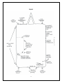
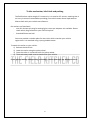
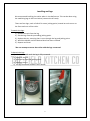
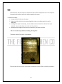
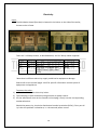
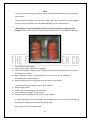
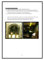
USER MANUAL 1 Trailer User Manual This manual contains all the technical specifications and instructions on set-up and use of all internal and external equipment. Contents Page Layout 3 Keys 4 Trailer hitchlock; towing and parking 6 Levelling and legs 7 Door, canopy and steps 8 Electricity and lighting 10 Gas 12 Water and waste 13 Appliances 15 Cleaning and return 16 Troubleshooting and Contacts 18 2 Layout 3 Keys Trailer door & hitch lock: There is a push-button key safe located on the A-frame of the trailer. The code for this is located on your booking confirmation. The push-button key safe contains two keys: one for the hitch lock and one for the trailer door. The trailer door is a barn door: this means that the top section may be opened independently. When the door is open it must be secured to prevent slamming. *Please note that the trailer door and hitch lock must be locked when the trailer is on hire and not in use. Gas, spare wheel, electricity, jacking legs lockers: These are all accessed using a T key. Please note that there is only one ‘T’ key per trailer and it is located in the first cupboard inside the kitchen on the right. We recommend that all lockers are kept locked when not in use. Fridges and freezer: Each fridge and freezer has a key. This is located in the fridge frame above each door and the key must remain in the lock. Remember to lock whilst in transit! Canopy: The canopy may be opened by releasing the antiluces and the spring bolts, as below: 1) Release the two antiluces, which are located on the exterior; lift the locking mechanism and drop it forward into a horizontal position. 2) Release the spring bolts, which are located inside. Pull the spring handle to the left and/or right (away from the canopy) until the bolt retracts through the ring fastening, then twist the handle upwards to keep it pinned back. 3) Push the canopy open. 4) Fold the antiluces back to the vertical position, and put the safety pin in. 4 To close the canopy: 1) Lift the antiluces’ locking mechanisms to a horizontal position. Check that the spring bolts are pinned back. 2) Carefully fold down the canopy and flip the antiluces’ to the vertical position. 3) Inside, release the spring bolts. 4) Replace the safety pin into the antiluces’ – see picture 3 *Please note that the canopy must be locked shut when the trailer is not in use. 5 Trailer mechanism, hitch lock and parking The field kitchen trailer weighs 2.5 tonnes dry. It is rated to 3.5 tonnes, meaning that it can carry 1 tonne of consumables providing your vehicle meets these requirements. Please check with your vehicle manufacturer. Our trailers are fitted with: - one 12V thirteen pin plug for towing lights; seven pin adaptors are available. Please check which plug connection your vehicle requires. - Standard 50mm tow ball. You must provide a number plate for the trailer which matches your vehicle registration. It is attached using a spring-loaded mount. To attach the trailer to your vehicle: 1) Release the hitch lock. 2) Lower the trailer using the jockey wheel. 3) Once the trailer is connected raise the jockey wheel. 4) The break-away cable must be attached to your vehicle. If you are not familiar with attaching and towing a trailer please do not attempt to do so. 6 Levelling and legs We recommend levelling the trailer when in situ before use. This can be done using the stabilising legs in the front locker (nearest the A frame). There are four legs, each of which fit onto a jacking point, located at each corner on the front and rear of the trailer. To attach the legs: 1) Remove the pin from the leg. 2) Slot the leg onto the protruding jacking point. 3) Replace the pin, ensuring that it runs through the leg and jacking point. 4) Wind the handle until the desired level has been reached. 5) Repeat until level. *Do not attempt to move the trailer with the legs connected. To detach the legs: 1) Wind the handle until the leg is fully retracted. 2) Remove the pin. 3) Pull the leg from the jacking point. 4) Replace the pin. 5) All legs should be stowed in their locker. 7 Door, canopy, slide-out and steps For information regarding the keys for door and canopy please refer to page 2. Trailer door: The trailer door is a barn door: this means that the top section may be opened independently. When the door is open it must be secured to prevent slamming. * The trailer door and hitch lock must be locked when the trailer is not in use. Canopy: The canopy may be opened by releasing the antiluces and the spring bolts, as below: 1) Release the two antiluces, which are located on the exterior; lift the locking mechanism and drop it forward into a horizontal position. 2) Release the spring bolts, which are located inside. Pull the spring handle to the left and/or right (away from the canopy) until the bolt retracts through the ring fastening, then twist the handle upwards to keep it pinned back. 3) Push the canopy open. 4) Fold the antiluces back to the vertical position and insert the safety pin. To close the canopy: 1) Lift the antiluces’ locking mechanisms to a horizontal position. Check that the spring bolts are pinned back. 2) Carefully fold down the canopy and flip the antiluces’ to the vertical position. 3) Inside, release the spring bolts. *The canopy must be closed and locked when the trailer is not in use. Slide-out: To extend the slide-out: 1) Ensure the canopy is open. 2) Inside, lift the spring bolts on either side of the slide-out. 3) Push the slide-out to fully extend. 4) Drop the spring bolts back into their lowered position. To stow the slide-out: 1) Lift the spring bolts. 2) Pull the slide-out towards you. 3) Drop the spring bolts through the catches so that the slide-out is secured. *The slide out must be secured with the internal spring bolts at all times. 8 Steps: Please ensure that the steps are attached to the trailer body before use. The steps are located inside hooked onto the shelves opposite the oven. To attach the steps: 1) Locate the bolt holes on the steps. 2) Align the holes with the corresponding bolts that protrude beneath the trailer doorway. 3) Holding the steps horizontally, slot the holes onto the bolts then lower the steps towards you, so that they are in the correct position. 4) Wind down the legs on the steps to ensure they are level and safe. *Do not use the steps without levelling the legs first. The black square foot spins up and down. Please make sure the steps are put back inside the kitchen before travelling anywhere. 9 Electricity Input: The distribution board (fuse box) is located in the locker on the side of the trailer, closest to the A frame. There are 3 x 32amp sockets, as detailed below, and 3 x 32amp cables supplied: Socket 1 2 3 Amps 32 32 32 Powers Coffee machine/bain marie Oven x 2 Ring main, life support light, fridges, freezer, lights, water pump Manual page 13-14 13-14 13-14 *Note that insufficient electricity supply could lead to equipment damage. Please refer to the manual pages 14-15 for specific information on each piece of equipment and appliance. To power the trailer: 1) Locate the cables in the electricity locker. 2) The male plug is to be attached to the generator or power source. 3) Lift the waterproof cover on the female end and plug it firmly into the corresponding numbered socket. Should the power trip, check the distribution board trip switches (PCDs); if they are all ‘up’ then the problem is elsewhere, i.e. the external power source. 10 Lighting: The light switches are located inside above the door. Switch 1 2 3 Florescent work lights Service spot lights External lights Extractor light The extractor light switch is located on its control panel towards the top left of the extractor fan. Life support light The ‘life support’ light is located above the door on the exterior of the trailer. When this light is on, it indicates that the ring main (PLUG 3) is supplied with power. Small appliances: The 13amp (household) plugs located around trailer are capable of supplying a total of 6000 watts. Please see the table below for examples of small appliances’ power consumption and note that this is an estimate only. Small appliance Kettle Radio/stereo Panini grill/toastie machine Toaster Blender Stand mixer Wattage 3000 W 60 W 650 – 1800 W 2000 W 300 W 300 – 1500 W All our appliances PAT tested. 11 Gas The trailer requires two gas cylinders to run the boiling table (six burner hob) and the water boiler. The gas locker, located on the side of the trailer, can carry a maximum of two 19kg gas cylinders. Larger cylinders may be used depending on your requirements. *Gas cylinders stored in the locker must be secured at all times using the straps supplied. The pictures below show the yellow shut off valve in the OPEN/ON position. 4) To connect the gas supply: Open the gas locker (see the keys page 4). There are two black rubber gas tails (hoses) each with a hand-wheel screw; screw one onto each gas cylinder. When both gas cylinders are connected, turn one or both on, as required, by unscrewing the valve at the top. Secure the gas cylinders using the strap and close the gas locker. 1) 2) 3) 4) To disconnect the gas supply, or to change a bottle: Open the gas locker. Release the strap holding the gas cylinders. Screw both gas cylinders’ valves closed. Unscrew the hand-wheel and remove the gas cylinder. 1) 2) 3) It is also possible to connect an additional gas appliance next to the 6 burner hob using the bayonet fitting located behind the boiling table. All our appliances are CORGI tested. 12 Water and waste *Oil and food should not be put down the sink! Water input: Standard hose lock fitting (supplied) and on-board 200 litre tank. Remember to turn the water boiler on to get a hot water supply. This is a switch located at hip height by the sink area. Water Tank The tank may be filled and used without further supply. Alternatively, as soon water is connected to the tank the pump will enable water to be used in the trailer, without having to fill the tank entirely. To fill the tank: 1) Take the hose located in the locker at the front of the trailer by the A frame (see layout on page 3). 2) Plug one end into the water input, located on the exterior in the recess beside the gas locker. 3) Plug the other end into your water supply. To empty the tank: 1) Turn off the water supply and disconnect the hose, if attached. 2) Locate the valve underneath the trailer, on the side with the lockers (see layout on page 3). 3) Turn the valve so that it is vertical to open it and allow the water to run out. 4) Once the water has ceased, return the valve to the horizontal closed position. The tank should be emptied before return or transport. Water pump: The trailer is supplied with a pump to take the water from the tank to the taps. It works automatically (once electricity is supplied). Please see trouble shooting or emergency contacts should it not work. Waste water: All waste water leaves through a grey water pump. This must be connected using the hose length supplied. 13 To connect the waste water hose: 1) Select the required waste hose length from beneath the sink. 2) Locate the female hose outlet on the exterior of the trailer (see layout on page 3) 3) Fold the arms of the camlock away from you, insert the male waste hose, then pull the arms back towards you, returning them to the locked position. 4) Insert the other end of the waste hose into your chosen receptacle. Below Left: The large black round inlet is for a manual feed. Below this the left metal nozzle is for water in and the copper pipe is the breather/water overflow. Below Right: Waste water hose connection located under the kitchen. 14 Appliances Undercounter 3 door fridge – Polar G622 All fridge appliances must have their doors locked for transit Electrical supply is on the ring main Upright fridge – Polar CD084 All fridge appliances must have their doors locked for transit As above Undercounter freezer – Polar CD081 All fridge appliances must have their doors locked for transit Boiling Table Turn on the main gas supply using the yellow lever – turn to 3 o’clock. Choose the gas ring you want to light and find corresponding tap Turn tap from 12 o’clock (off) to 10 o’clock – holding in the Thermo couple Light the ring using a long lighter and keep the button depressed for 3 seconds. Turn tap to adjust gas power. To turn off turn tap back to 12 o’clock (off). Turn off main gas supply when leaving the trailer unused. Oven Blue seal turbo fan E31D4 Please secure the doors for transit Push Blue power button to turn on Set required temperature – the initial warm up will use alot of power The digital display light will let you know when the oven has reached the required temperature Push Blue power button to turn off Water boiler – Morco F-11 EL To switch the water boiler on flick the light switch at hip height under the counter by the sinks. It should automatically ignite when the hot water tap is turned on. Extractor Fan Please turn on as soon as you start using the ovens, boiling table or any other hot cooking equipment. There is a light for the extractor; the switch is on the front left next to the on off switch. 15 Cleaning and return The trailer must be thoroughly cleaned before return. This includes all interior and exterior fittings, fixtures and appliances, including any moveable or removable parts, and anything additionally hired. All perishables must be removed. *Please do not use any acid, wire brushes or abrasive cleaners Checklist for cleaning: Ceiling Walls Surfaces including slide-out Cupboards and shelves Floor Extractor Exterior edge Interior edge Baffles x 4 – must be completely removed, both parts cleaned, dried and replaced Fridges x 2 Exterior Interior Racks Freezer Exterior Interior Racks Oven x 2 Exterior Interior Racks Boiling table Grease traps Burners Sink and taps Cables and hoses Electrical cables Water hoses Waste hoses 16 Gas cylinders Lockers Signage, decoration or extras applied to the interior or exterior Glue residue Additionally hired equipment or appliances Coffee machine Bain marie Exterior Inserts Return checklist: Perishables removed Slide-out secured (see page 7) Empty water tank Water hose disconnected and stored Waste hose disconnected and stored Gas cylinders closed and stored Electrical cables disconnected and stored Legs removed and stored (see page 6) All lockers locked (see page 4) Lock fridges and freezer (see page 4) Secure oven doors Canopy locked (see page 7) Door locked T key returned to under sink Trailer and hitch lock key returned to push-button key safe Please be aware that photographs and a hire check in/out sheet recording the interior and exterior of the trailer will be taken on delivery and return. If any damage has been caused during the hire period, please inform us as soon as possible and include supporting photographs. 17 Troubleshooting See also Disaster Recovery document Please call 07766 861405 if you have any questions or queries Contacts In case of breakdown when towing, please call: Andrew McCabe 07538 368 825 (24 hrs) Evean Recovery 020 7476 3000 (24 hrs) Kavanagh Rescue and Recovery 020 8394 4999 (24 hrs) 18