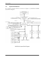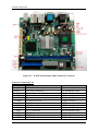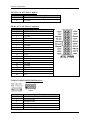
1
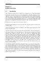
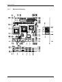
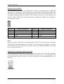
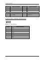
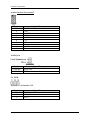
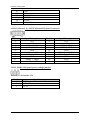
WADE-8141
Mini ITX Main Board
User's Manual
Version 1.1
Copyright © Portwell, Inc., 2006. All rights reserved.
All other brand names are registered trademarks of their respective owners.
Preface
Table of Contents
How to Use This Manual
Chapter 1 System Overview.......................................................................................................1-1
1.1 Introduction.................................................................................................................................. 1-1
1.2 Check List ..................................................................................................................................... 1-2
1.3 Product Specification .................................................................................................................. 1-2
1.3.1 Mechanical Drawing......................................................................................................... 1-4
1.4 System Architecture .................................................................................................................... 1-5
Chapter 2 Hardware Configuration ...........................................................................................2-1
2.1 Jumper Setting ............................................................................................................................. 2-1
2.2 Connector Allocation .................................................................................................................. 2-1
Chapter 3 System Installation....................................................................................................3-1
3.1 Socket 478/479 Processors ......................................................................................................... 3-1
3.2 Main Memory .............................................................................................................................. 3-3
3.3 Installing the Mini ITX................................................................................................................ 3-3
3.3.1 852GM Integrated Graphics Controller.......................................................................... 3-4
3.3.2 Dual Realtek 81xx 10/100 Base-TX Ethernet controller............................................... 3-5
3.3.3 Drivers Support ................................................................................................................. 3-5
Chapter 4 BIOS Setup Information............................................................................................4-1
4.1 Entering Setup.............................................................................................................................. 4-1
4.2 Main Menu ................................................................................................................................... 4-2
4.3 Standard CMOS Features ........................................................................................................... 4-3
4.4 Advanced BIOS Features............................................................................................................ 4-4
4.4.1 CPU Feature ....................................................................................................................... 4-5
4.5 Advanced Chipset Features ....................................................................................................... 4-8
4.6 Integrated Peripherals .............................................................................................................. 4-11
4.6.1 OnChip IDE Device......................................................................................................... 4-12
4.6.2 Onboard Device............................................................................................................... 4-13
4.6.3 Onboard I/O Chip Setup ............................................................................................... 4-15
4.7 Power Management Setup ....................................................................................................... 4-18
4.8 PnP/PCI Configurations .......................................................................................................... 4-21
4.8.1 IRQ Resources.................................................................................................................. 4-23
4.9 PC Health Status........................................................................................................................ 4-24
4.10 Frequency/Voltage Control................................................................................................... 4-25
4.11 Set Supervisor Password ........................................................................................................ 4-26
4.12 Set User Password ................................................................................................................... 4-27
Preface
How to Use This Manual
This manual is written for the system integrator, PC technician and knowledgeable
PC end user. It describes how to configure your WADE-8141 to meet various
operating requirements. The user’s manual is divided into four chapters, with each
chapter addressing a basic concept and operation of the server board.
Chapter 1 : System Overview. Presents what you have inside the box and gives you
an overview of the product specifications and basic system architecture for the
WADE-8141 server board.
Chapter 2 : Hardware Configuration. Shows the definitions and locations of Jumpers
and Connectors so that you can easily configure your system.
Chapter 3 : System Installation. Describes how to properly mount the CPU, main
memory, and M-System Flash disk for a safe installation. It will also introduce and
show you the driver installation procedure for the Graphics Controller and Ethernet
Controller.
Chapter 4 : BIOS Setup Information. Specifies the meaning of each setup parameter,
how to get advanced BIOS performance and update to a new BIOS
The content of this manual and EC declaration document is subject to change without
prior notice. These changes will be incorporated in new editions of the document.
Portwell may make supplement or change in the products described in this
document at any time.
Updates to this manual, technical clarification, and answers to frequently asked
questions will be shown on the following web site : http://www.portwell.com.tw
System Overview
Chapter 1
System Overview
1.1
Introduction
The WADE-8141 Series all-in-one Mini ITX is designed to fit a high performance
Pentium M / Celeron M processor and compatible for high-end computer system
application with PCI bus architecture. It is made to meet today’s demanding pace,
and keep complete compatibility with hardware and software designed for the IBM
PC/AT. The on-board devices support one PCI slot and integrated graphics and
on-board Dual Marvell Gigabit Ethernet controller. It’s beneficial to build up a high
performance and high data availability system for VARs, or system integrators.
WADE-8141 Series support the following processors:
Intel ® Pentium ® Mobile processor Socket 478/479 supporting based on 0.90 micron
(CPUID = 0xh).
Intel ® Celeron M ® processor ULV 800MHz /1Ghz (90nm) supporting based on 0.90
micron (CPUID = 0xh).
This Mini ITX can run with Intel Socket 478/479 Pentium M / Celeron M processors,
and support DIMM up to 1GB DDR Memory. The enhanced on-board two PCI-IDE
interface can support 4 drives up to PIO mode 4 timing and Ultra
ATA33/66/100/133 synchronous mode feature , The on-board Super I/O chipset
support four serial ports, one SIR (Serial Infrared) port, and one parallel port. Fourth
high performance 16C550-compatible UARTs provide 16-byte send/receive FIFOs
and the multi-mode parallel port supports SPP/EPP/ECP function. three RS-232
serial port interface and one RS-232 pin herder .Besides, H/W monitor function, ,
Intel High Definition Audio as 5.1 surround sound , Hi-Speed USB 2.0 x 6 ports offer
up to 40X greater bandwidth over USB 1.1 Also provide dual display function by
VGA and LVDS interface..
The Mini-ITX standard makes the WADE-8141 Series work with the one slot PCI .
One 6-pin Mini-DIN connectors are provided to connect PS/2 mouse and keyboard.
The on-board Flash ROM is used to make the BIOS update easier. The high precision
Real Time Clock /calendar is built to support Y2K for accurate scheduling and
storing configuration information. One 20-pin standard connector is designed to
support ATX power function. A feature of CPU overheat protection will give user
more security and stability. All of these features make WADE-8141 Series excellent in
stand-alone applications.
WADE-8141 User’s Manual
1-1
System Overview
1.2
Check List
The WADE-8141 package should cover the following basic items
One Quick Installation Guide for WADE-8141 series
User’s Manual (this manual in PDF file format)
One WADE-8141 Mini ITX
One 34pin FDD cable
One 40pin IDE cable
One 26pin Parallel Port cable
One 9pin COM 4 Port cable
One USB 2.0 cable
One I/O Shield
One CD-Title to support internal VGA display driver network controller driver.
If any of these items is damaged or missing, please contact your vendor and keep all
packing materials for future replacement and maintenance.
1.3
Product Specification
CPU
- Support Intel Pentium Mobile / Celeron M processor up to 2.1GHz and above or
Celeron M processor 800MHz / 1GHz on board
- CPU bus clock : 400 MHz
Chipset Intel® 82852GM GMCH & 82801DB ICH4 Main Memory
- One 184-pin DIMM socket
- 256 MB to 1GB using 256MB/512MB/1GB
- Supports up to CL2 or 2.5 or 1 DIMMs at DDR200/DDR266/333MHz memory
bus.
System BIOS
- AWARD BIOS with PC’99 support
- FWH 4Mb Flash ROM for easy upgrades
- Support ACPI, DMI, PnP, and Green function
Super I/O Winboand W83627EHG
- Serial Ports : Support Four RS232 ports
- IrDA Interface : Support one Infrared port
- Parallel Port : Support one SPP, EPP/ECP bi-directional parallel port
Storage IDE Interface
Support Two Ultra DMA 33/66/100/133 support four IDE devices by one 44-pin
(Master) and one 40-pin IDE connector, one Compact Flash socket (reverse side)
WADE-8141 User’s Manual
1-2
System Overview
USB
Support 6 x USB 2.0 ports
Keyboard and PS/2 Mouse Interfaces
Support two mini-DIN 6-pin connectors for Keyboard and Mouse.
Auxiliary I/O
- One 2-pin system reset switch
- One 2-pin system power on LED
- One 2-pin HDD active indicator interface
- One 2-pin ATX power control interface
- Two 3-pin headers for CPU and system fan
Real-Time Clock/Calendar (RTC)
- Build-in ICH4
- Y2K compliant
System Monitoring and Protection
- Monitoring system temperature, voltage, and cooling fan status
- Auto throttling control when CPU overheats
- System automatically restored on recovery of AC power loss
Wake On LAN & Modem Ring on
Support system wake up function from Network and Modem
On-chip VGA Display
- Intel® FW82852GM GMCH integrated Extreme Graphics controller
- One DSUB-15 connector for CRT display interface.
- Two LVDS connectors for 18bit dual channel LVDS panel display interface.
- CRT mode: Support Maximum resolution up to 2048 x 1536 for 3D at refresh
rates 75Hz.
- Multiple Maximum overlay display resolution up to 1600 x 1200 (85Hz)
On-board Ethernet Function
- Support dual Ethernet function two RJ-45 interface ports, by Realtek (8100C)
Ethernet controller support 10/100BASE-T
- Support two LED indicators to display active and link message
One PCI Interfaces
Support one extended PCI slot compliant with PCI 2.2 specification.
Physical and Environmental requirements :
- Outline Dimension (L x W) : 170mm (6.69 inch) X 170mm (6.69 inch)
- Power Requirements: +5V@165mA (typical), +12V@405mA, -12V@61mA,
[email protected]
- Operating Temperature : 0 ~ 60 ℃
- Storage Temperature : -20~70℃
- Relative Humidity : 5% to 95%, non-condensing
WADE-8141 User’s Manual
1-3
System Overview
1.3.1
Mechanical Drawing
北橋Sink
CPU Sink
WADE-8141 User’s Manual
1-4
System Overview
1.4
System Architecture
All of details operating relations are shown in (Figure 1-1) WADE-8141 SERIES
System Block Diagram.
WADE-8141 System Block Diagram
WADE-8141 User’s Manual
1-5
Hardware Configuration
Chapter 2
Hardware Configuration
This chapter indicates jumpers’, headers’ and connectors’ locations. Users may find
useful information related to hardware settings in this chapter. The default settings
are indicated with a star sign (Ì).
2.1
Jumper Setting
In general, jumpers on the Mini ITX are used to select options for certain features.
Some of the jumpers are designed to be user-configurable, allowing for system
enhancement. The others are for testing purpose only and should not be altered. To
select any option, cover the jumper cap over (SHORT) or remove (NC) it from the
jumper pins according to the following instructions. Here, NC stands for “Not
Connect”.
2.2
Connector Allocation
I/O peripheral devices are connected to the interface connectors (Figure 2-1)
WADE-8141 User’s Manual
2-1
Hardware Configuration
Figure 2-1 WADE-8141 Jumper and Connector Locations
Connector Function List
Connector
QN5
PANEL1 1-3
PANEL1 2-4
PANEL1 6-8
PANEL1 5-7
COM1
COM2
COM3
COM4
DIO
LPT
USB1
USB2
Function
RTC CMOS Clear
IDE active indicator
System Power On LED
System Power on Switch
System reset
COM1 serial port
COM2 serial port
COM3 serial port
COM4 serial port
DI/O connector
Parallel port connector
USB 2.0 port 1
USB 2.0 port 2
WADE-8141 User’s Manual
Remark
1x3 shrouded header
1x2 shrouded header
1x2 shrouded header
1x2 shrouded header
1x2 shrouded header
COM1 connector
COM2 connector
COM3 connector
2x5 shrouded header
2x4 shrouded header
13x2 header, pitch 2.54mm
USB1LAN1 connector
USB1LAN1 connector
2-2
Hardware Configuration
USB3
USB4
USB5
USB3
JP1
JP2
AUDIO1
ATX_PWR
VGA
LVDS
LCD Inverter
LVDS_PWR
IDE0
IDE1
KBMS1
CPU_FAN
SYS_FAN
USB 2.0 port 3
USB 2.0 port 3
USB 2.0 port 3
USB 2.0 port 3
Setting COM1 / COM2 ring function
Setting COM3 / COM4 ring function
AUDIO interface
20-PIN ATX Power connector
DUB-15 port
Dual Channel 24 bit LVDS
LVDS Inverter power voltage
Setting LVDS power voltage
IDE0 (Primary) interface
IDE1 (Secondary) interface
PS/2 keyboard & mouse connector
CPU FAN connector
System Fan connector
USB2LAN2 connector
USB2LAN2 connector
2x5 shrouded header
2x5 shrouded header
2x5 shrouded header
2x5 shrouded header
2x5 shrouded header
2x10 power connector
VGA connector
Hirose DF13-20DP
Hirose DF13-9DP
1x3 shrouded header
22x2 header, pitch2.0mm
20x2 header, pitch 2.54mm
Double deck connector
3x1wafer , pitch 2.54mm
3x1wafer , pitch 2.54mm
QN5 : RTC CMOS Clear Jumper Setting
Normal: 1-2 Short Ì
Clear CMOS: 2-3 Short
PANEL1 5-7: System Reset
Pin No.
7
9
Signal Description
Reset
Ground
Panel1 1-3: IDE1 active indicator
Pin No.
1
3
Signal Description
+5V (Pull-up for HDD LED)
HDD active# (LED cathode terminal)
WADE-8141 User’s Manual
2-3
Hardware Configuration
PANEL1 6-8: ATX Power Button
Pin No.
6
8
Signal Description
Power button control signal
Ground
PWR1: ATX_20P Power Connector
Pin No.
1
2
3
4
5
6
7
8
9
10
11
12
13
14
15
16
17
18
19
20
Signal Description
+3.3V
+3.3V
Ground
+5V
Ground
+5V
Ground
PW_OK
+5V SB
+12V
+3.3V
-12V
Ground
PS ON
Ground
Ground
Ground
-5V
+5V
+5V
COM1/COM2/COM3/COM4 Interface
Pin No.
1
2
3
4
5
6
Signal Description
Data Carrier Detect
Received Data
Transmit Data
Data Terminal Ready
Ground
Data Set Ready
WADE-8141 User’s Manual
2-4
Hardware Configuration
7
8
9
10
Request To Send
Clear To Send
Ring Indicator
Not used
DIO Interface
Pin No.
1
2
3
4
5
6
7
8
Signal Description
GPIO 32
GPIO 36
GPIO 33
GPIO 37
GPIO 34
GPIO 38
GND
GND
PWR1 : ATX_24P2R Power Connector
Pin No.
1
3
5
7
9
11
13
15
17
19
21
23
25
Signal Description
STB#
D1
D3
D5
D7
BUSY
SLCT
ERR#
SLIN#
GND
GND
GND
GDN
WADE-8141 User’s Manual
Pin No.
2
4
6
8
10
12
14
16
18
20
22
24
26
Signal Description
D0
D2
D4
D6
SCK#
PE
AFD#
INIT#
GND
GND
GND
GND
NC
2-5
Hardware Configuration
External USB3 (USB2.0)
This motherboard provides one USB headers on the board allowing for 2 additional
USB ports. To make use of this header, you must attach a USB bracket/cable with
USB ports (some models will come packaged with a USB 2-port bracket-cable). The
optionally packaged bracket will have two connectors that you can connect to the
headers (USB1, USB2). The other end (bracket containing the USB ports) is attached to
the computer casing.
Pin No.
1
3
5
7
9
Signal Description
5VSB
Data_AData_A+
GND
NC
Pin No.
2
4
6
8
10
Signal Description
5VSB
Data_BData_B+
GND
GND
Note:
If you are using a USB 2.0 device with Windows 2000/XP, you will need to install the
USB 2.0 driver from the Microsoft® website. If you are using Service pack 1 (or later)
for Windows® XP, and using Service pack4 (or later) for Windows® 2000,you will not
have to install the driver.
USB & LAN Connectors: USB/ b LAN 1&2
This motherboard comes with 4 USB ports and two LAN ports. The USB connectors
are used to attach to keyboards, mice and other USB devices. You can plug the USB
devices directly into this connector. The LAN connectors can be attached directly to a
network.
WADE-8141 User’s Manual
2-6
Hardware Configuration
Pin No.
1
2
3
4
Pin No.
1/5
2/6
Signal Description
TX+
TXRX+
NC
Pin No.
5
6
7
8
Signal Description
NC
RXNC
NC
Signal Description
+5 V (fused)
USBP0-/P1-
Pin No.
3/7
4/8
Signal Description
USBP0+/P1+
Ground
JP1/JP2: for COM1~COM4 Ring Function Selectors
Default is 7-9 & 8-10 short
Pin No.
1
2
3
4
5
6
7
8
9
10
Signal Description
VCC5
VCC5
XNR11
XNR12
VCC12
VCC12
XNR11
XNR12
NR11
NR12
WADE-8141 User’s Manual
2-7
Hardware Configuration
Audio function for external
Pin No.
1
2
3
4
5
6
7
8
9
10
Signal Description
F_MIC1
GND
F_MIC2
VCC5
LOUTR
F_R
NC
NC
LOUTL
F_L
Audio Jack
Pin No.
1(Orange)
2(Black)
Signal Description
Speak-Out
MIC-in
CF_PWR
Default is 1-2 short be 3.3V
Pin No.
1
2
3
Signal Description
VCC3
VCC_CF
VCC5
WADE-8141 User’s Manual
2-8
Hardware Configuration
CPU_FAN / SYS_FAN
Pin No.
1
2
3
Signal Description
Ground
+12V
RPM signal
PS/2 Keyboard & Mouse(KBMS1)
Pin No.
1
2
3
4
5
6
Signal Description
Keyboard Data
Mouse Data
Ground
+5V
Keyboard Clock
Mouse Clock
VGA D-SUB15 Connector
Pin No.
1
2
3
4
5
6
7
8
9
Signal Description
Red Signal
Green Signal
Blue Signal
NC
GND
GND
GND
GND
VCC
WADE-8141 User’s Manual
2-9
Hardware Configuration
10
11
12
13
14
15
GND
NC
DCC_DATA
HSYNC
VSYNC
DCC_CLK
LVDS 1(Channel A) / LVDS 2(Channel B) panel Connector
Pin No.
1
3
5
7
9
11
13
15
17
19
Signal Description
VCC
VCC
YAM0 / YBM0
YAP0 / YAP0
GND
YAM1 / YBM1
YAP1 / YBP1
GND
YAM2 / YBM2
YAP2 / YBP2
Pin No.
2
4
6
8
10
12
14
16
18
20
Signal Description
VCC
VCC
YAM3 / YBM3
YAP3 / YBP3
GND
CLKAM / CLKBM
CLKAP / CLKBP
GND
GND
GND
LVDS_PWR LVDS panel power voltage jumper
Default is 1-2 short be 3.3V
Pin No.
1
2
3
Signal Description
VCC3
VCC_CF
VCC5
WADE-8141 User’s Manual
2-10
Hardware Configuration
LCD Inverter Power voltage Connector
LCD inverter power voltage
Pin No.
1
2
3
4
5
Signal Description
VCC12M1
VCC5V
VCC12M1
LVDS_BKLTEN
GEN
Compact Flash Connector
Pin No.
1
3
5
7
9
11
13
15
17
19
21
23
25
27
29
31
33
35
37
39
41
43
45
47
49
Signal Description
GND
HD04
HD06
CS0#
GND
GND
VCC
GND
GND
A01
HD00
HD02
CD2#
HD11
HD13
HD15
NC
HIOW#
INTRQ
CSEL#
RESET#
DMAREQ
DASP#
HD08
HD10
WADE-8141 User’s Manual
Pin No.
2
4
6
8
10
12
14
16
18
20
22
24
26
28
30
32
34
36
38
40
42
44
46
48
50
Signal Description
HD03
HD05
HD07
GND
GND
GND
GND
GND
A02
A00
HD01
IOCS16#
NC
HD12
HD14
CS1#
HIOR#
WE#
VCC
NC
IORDY
DMAACK#
PDIAG#
HD09
GND
2-11
System Installation
Chapter 3
System Installation
This chapter provides you with instructions on how to setup your system. The
additional information shows you how to install CPU/ FAN and memory.
3.1
Socket 478/479 Processors
Installing Pentium M / Celeron M Processor
I. The processor socket comes with a screw to secure the processor, please unlock the
screw first.
II. Position the CPU above the socket and the gold triangular mark on the CPU
must align with pin 1 of the CPU socket. Then Insert the CPU gently seated in
place.
III. Turn the screw to the lock position.
Unlock
Lock
Pin 1 of the
socket
Gold
triangular
mark
Notes:
(1) Do not force the CPU into the socket. It may bend the pins and damage the CPU
(2) WADE-8141 (On-Board CPU) no need to installed .
WADE-8141 User’s Manual
3-1
System Installation
Installing Processor FAN Cooler and Heat Sink
1. Tear the sticker off on the bottom of the CPU cooler which combined with the fan
and heat sink.
2. Place the CPU cooler right upon the buckle holes.
Fan
Heat Sink
Sticker
Buckle
Buckle holes
CPU fan connector
CPU Installed
(Rear side)
Notes:
(1) Make sure the CPU fan and heat sink assembly and the CPU top surface are in
total contact to avoid CPU overheating problem that would cause the system to
hang or unstable.
(2) The WADE-8141 (On-Board PCU) no need it , which it already have CPU heat sink
for fan less.
WADE-8141 User’s Manual
3-2
System Installation
3.2
Main Memory
WADE-8141 Series provides 1 DIMMs (184-pin Dual In-line Memory Module) to
support 2.6V DDRAM (Synchronized DRAM) as on-board main memory. The
maximum memory size is 256B~ 1GB with using 256MB/512MB/1GB technology.
Supports up to 1 double sided DIMMs at 266/333 MHz. The memory architecture
adopts 128-bit data interface to support for x8 and x16 DDRAM(DDR1) device width.
In addition, it only support Non-ECC memory.
For system compatibility and stability, don’t use memory module without brand.
You can also use the single or double-side DIMM .The three DIMMs can be out of
order. You can install different size of DDRAM module on DIMM1, or all to boot up
system.
Without out the contact and lock integrity of memory module with socket, it will
impact on the system reliability. Follow normal procedure to install your DDRAM
module into memory socket. Before locking, make sure that the module has been
fully inserted into the DIMM slot.
Note:
For maintaining system stability, do not change any of DDR memory parameters in
BIOS setup to upgrade your system performance without acquiring technical
information.
3.3
Installing the Mini ITX
To install your WADE-8141 Series into standard chassis or proprietary environment,
you need to perform the following steps:
1. Check all jumpers setting on proper position
2. Install and configure CPU and memory module on right position
3. Place WADE-8141 Series into the dedicated position in your system
4. Attach cables to existing peripheral devices and secure it
Note:
Please refer section 3.4 to install display and Ethernet drivers and setup your system.
WARNING:
Please ensure that your SBC properly inserted and fixed by mechanism. Otherwise,
the system might be unstable or do not work from bad contact of golden finger.
WADE-8141 User’s Manual
3-3
System Installation
3.3.1
852GM Integrated Graphics Controller
Intel® FW82852GM GMCH integrated Extreme Graphics controller, one DSUB-15
connector for CRT display interface. Two LVDS connectors for 18bit dual channel
LVDS panel display interface. CRT mode :Support Maximum resolution up to 2048 x
1536 for 3D at refresh rates 75Hz. Multiple Maximum overlay display resolution up
to 1600 x 1200 (85Hz).
The 852GM supports the modes which appear in the table below.
WADE-8141 User’s Manual
3-4
System Installation
3.3.2
Dual Realtek 81xx 10/100 Base-TX Ethernet controller
Dual Realtek 81xx 10/100 BASE-TX Ethernet controller by PCI .
The WADE-8141 Series provides two LED indicators on RJ-45 connector to show
LAN interface status.
These messages will give you a guide for troubleshooting.
Yellow LED indicates transmit and receive activity.
Blinking : indicates transmit/receive activity
On : indicates no activity but link is valid
Off : link is invalid
Green LED indicates Link speed
On : link speed at 100Mbps
Off : link speed at 10Mbps
3.3.3
Drivers Support
WADE-8141 Series provides on CD-Title to support on-board VGA and Ethernet
device drivers in various operating systems. Before installing the device drivers,
please see the reference files in each sub-directory. You cannot install drivers from
CD-Title directly.
CD-Title List:
852GM CHIPSET INTEGRATED GRAPHY: support Win2000, XP , Win2003
and … environment
INTEL 852GM & ICH4(R) CHIPSET DRIVER: support Win2000 , XP , Win2003
and … environment
Dual Realtek 81xx Ethernet controller driver support :Win2000 , XP , Win2003 ,
and….. environment
Audio AC97 Realtek ALC 655 codec controller driver support: Win2000 , XP ,
Win2003 , and….. environment
WADE-8141 User’s Manual
3-5
BIOS Setup Information
Chapter 4
BIOS Setup Information
WADE-8141 series is equipped with the Phoenix (AWARD) BIOS stored in Flash
ROM. These BIOS has a built-in Setup program that allows users to modify the basic
system configuration easily. This type of information is stored in CMOS RAM so that
it is retained during power-off periods. When system is turned on, WADE-8141 series
communicates with peripheral devices and checks its hardware resources against the
configuration information stored in the CMOS memory. If any error is detected, or
the CMOS parameters need to be initially defined, the diagnostic program will
prompt the user to enter the SETUP program. Some errors are significant enough to
abort the start-up.
4.1
Entering Setup
Phoenix-Award BIOS has a built-in setup program that allows users to modify the
basic system configuration. This information is stored in CMOS RAM whose power is
supplied by a battery so that it can retain the setup information even when the power
is turned off. Press Delete when you Power on or Reboot the computer system. (i.e.
After the logo appears at the center of the screen, please press Delete to enter the BIOS
setup program). In the BIOS, make sure that everything is working fine before you try
to optimize it for maximum performance.
↑↓→ ←
Enter
+ / - /PU /PD
ESC
F1
F2
F5
F6
F7
F9
F10
General Help
: Move
: Select
: Value
: Exit
: General Help
: Item Help
: Previous Values
: Fail-Safe Defaults
: Optimized Defaults
: Menu in BIOS
: Save
WADE-8141 User’s Manual
4-1
BIOS Setup Information
4.2
Main Menu
When you enter the PHOENIX-AWARD™ CMOS Setup Utility, the Main will appear
on the screen. The Main allows you to select several configuration options. Use the
left/right arrow keys to highlight a particular configuration screen from the top
menu bar or use the down arrow key to access and configure the information below.
WADE-8141 User’s Manual
4-2
BIOS Setup Information
4.3
Standard CMOS Features
Date (mm/date/year) and Time (hh/mm/ss)
Allow you to change the date and time of the system clock. No matter how good the
quality of the motherboard, remember that losing (or gaining) several seconds per
month is not a surprising thing.
IDE Channel 0 Master/Slave
You can press Enter to see the submenus they contain.
IDE Channel 1 Master/Slave
You can press Enter to see the submenus they contain.
Drive A
You can press Enter to see the submenus they contain. Available options are
360K/5.25 in ,1.2M/5.25 in ,720K/3.5 in, 1.44M/3.5 in , 2.88M/ 3.5 in
Video
Allows you to select the type of displaying standard you are using. Available options
are EGA/VGA, CGA 40, CGA 80 and MONO.
WADE-8141 User’s Manual
4-3
BIOS Setup Information
Halt On
Select the situation in which you want the BIOS to stop the POST process and notify
you. Available options are All Errors, No Errors, All, but keyboard, All, but
diskette, and All, but disk/key.
Base Memory
Displays the amount of conventional memory detected during boot up.
Extended Memory
Displays the amount of extended memory detected during boot up.
Total Memory
Displays the total memory available in the system.
4.4
Advanced BIOS Features
WADE-8141 User’s Manual
4-4
BIOS Setup Information
4.4.1
CPU Feature
Thermal Management
This BIOS feature controls the activation of the Thermal Monitor’ s automatic mode.
It allows you to determine when the Pentium M’ s Thermal Monitor should be
activated in automatic mode after the system boots. In general, the Thermal Monitor
should not be activated immediately on booting since the processor will be under a
heavy load during the booting process, which results in the sharp rise in die
temperature from its cold state, which leads to the unstable system. Therefore, to
ensure optimal booting performance, the activation of the Thermal Monitor must be
delayed for a set period of time. But how do you possibly know the optimal delay
time? It is recommended that you set this to its lowest value that exceeds the time it
takes to fully boot up your computer.
This item will monitor the CPU thermal to prevent the CPU damage from high
temperature.
TM2 BUS Ratio
Select the Represents the frequency (bus ratio of the throttled performance state that
will be initiated when the on-die sensor goes from not hot to hot.
WADE-8141 User’s Manual
4-5
BIOS Setup Information
TM2 BUS VID
Select Represents the voltage of the throttled performance state that will be initiated
when the on die sensor gose from not hot to hot.
Execute Disable Bit
Select when disable, forces the XD feature flag to always return 0.
CPU L1 & L2 & L3 Cache
Cache memory is much faster than conventional DRAM system memory. These fields
allow you to enable or disable the CPUs Level 1 built-in cache and Level 2 external
cache. Both settings are left as Enabled to significantly enhance the performance of
your computer.
Quick Power On Self Test
Enable this function to reduce the amount of time required to run the POST (Power
On Self Test). BIOS will save time by skipping certain tests during POST. It is
recommended that you disable this setting. Finding a problem during boot up is
better than loosing data during your work.
First/Second/Third/Other Boot Device
Allow you to select the First, Second and Third Boot Device. If your computer is
newly constructed, the next thing you want to do is load the Operating System from
scratch, directly off its CD. Before that, you need to set the First Boot Device to the
CDROM. This instructs the BIOS to boot from the CD drive before trying to boot from
the hard drive, which is still blank.
Boot Up Floppy Seek
This function defines the seek disk drivers during boot up. Disabling seed boot up.
Boot Up NumLock Status
This function defines the keyboard's numberpad as number keys or arrow keys. If it
is set at On the number keys will be activated, if it is set at Off the arrow keys will be
activated.
Gate A20 Option
Select if chipset or keyboard control should control Gate A20.
Typematic Rate Setting
When enabled, you can set the following two-typematic control items. When
disabled, the keyboard controller determines keystrokes arbitrarily in your system.
WADE-8141 User’s Manual
4-6
BIOS Setup Information
Typematic Rate (Chars/Sec)
The typematic rate sets the rate at which characters on the screen repeat when a key is
pressed and held down.
Typematic Delay (Msec)
The typematic delay sets how long after you press a key that a character begins
repeating.
APIC Mode
By enabling this option, “MPS version control for OS” can be configured. Disabled
is recommended.
MPS Version Control for OS
The 1.1 version is the older version that supports 8 more IRQs in the Windows NT
environment. Choose the new 1.4 version for Windows 2000 and Windows XP.
Options: 1.4 (default)、1.1
OS Select For DRAM > 64MB
IBM’s relic. If your system's DRAM is larger than 64MB and you are running OS/2,
select OS/2 as the item value. Otherwise, set the item value to Non-OS/2 for all other
operating systems.
Report No FDD For Win95
The original Windows 95 requires the presence of a floppy. Unless the BIOS tells it to
disregard the absence of the drive, it will generate an error message. For other
operating systems as Win98 etc this field is without relevance.
WADE-8141 User’s Manual
4-7
BIOS Setup Information
4.5
Advanced Chipset Features
DRAM Timing Selectable
This item determines DRAM clock/timing using SPD or manual configuration. Make
sure your memory module has SPD (Serial Presence Data), if you want to select the
“By SPD” option.
The choice: Manual、By SPD (default)
CAS Latency Time
CAS is short for column address strobe, which is a kind of signals. When the CPU
needs data from SDRAM, CAS signals will be sent via the CAS line to specify the
column where the data is needed. This controls the time delay (in clock cycles - CLKs)
that passes before the SDRAM starts to carry out a read command after receiving it.
This also determines the number of CLKs for the completion of the first part of a burst
transfer. In other words, the lower the latency, the faster the transaction.
WADE-8141 User’s Manual
4-8
BIOS Setup Information
Note that some SDRAM modules may not be able to handle the lower latency and
will become unstable and lose data. Therefore, set the DRAM CAS Latency Time to 2
for optimal performance if possible but increase it to 2.5 if your system becomes
unstable.
Interestingly, increasing the CAS latency time does have an advantage in that it will
enable the SDRAM to run at a higher clockspeed, thereby giving you an edge in
overclocking your system. So, if you hit a snag while overclocking, try increasing the
CAS latency time.
DRAM RAS# to CAS# Delay
This item allows you to select a delay time between the CAS and RAS strobe signals.
It only applies when DRAM is written to, read from, or refreshed. This field is
adjustable only when “DRAM Timing Selectable” is set to “manual”. This field is
locked when “DRAM Timing Selectable” is set to “By SPD” and is automatically
determined by the system.
The choice: 4、3、2
DRAM RAS# Precharge
This item allows you to select the DRAM RAS# precharge time. The ROW address
strobe must precharge again before DRAM is refreshed. An inadequate configuration
may result in incomplete data. This field is adjustable only when “DRAM Timing
Selectable” is set to “manual”. This field is locked when “DRAM Timing Selectable”
is set to “By SPD” and is automatically determined by the system.
The choice: 4、3、2
MGM Core Frequency
This field sets the frequency of the DRAM memory installed.
The choice: Auto Max 266MHz, 400/266/133/200 MHz, 400/200/100/200 MHz,
400/200/100/133 MHz, 400/266/133/267 MHz.
System BIOS Cacheable
Enabling this function allows caching of the system BIOS ROM at F0000h-FFFFFh,
which results in better system performance. However, if any program writes to this
memory area, a system error may result. It is advisable to leave it in default setting.
Caching the system BIOS results in better performance than shadowing the system
BIOS.
WADE-8141 User’s Manual
4-9
BIOS Setup Information
Video BIOS Cacheable
This feature is only valid when the BIOS is shadowed. It enables or disables the
caching of the video BIOS ROM at C0000h~C7FFFh via the L2 cache. This greatly
speeds performance because the OS bypasses the BIOS using the graphics driver to
access the video card’s hardware directly.
On-Chip VGA
This item is enabled as the onboard VGA is used.
The choice: Enable / Disable
On-Chip Frame Buffer Size
This item is to select the amount of system memory that will be utilized as internal
graphics device memory.
The choice: 1MB, 4MB, 8MB, 16MB, 32MB.
Boot Display
This item is to select the display device that the screen will be shown
The choice: CRT , LFP(LVDS), CRT+LFP(LVDS).
Panel Number
This item is to select the Panel display resolution that will be displayed depending on
the LCD panel (LFP)
The choice: 640x480 18 / 800x600 18 / 1024x768 18 / 1280x1024 24x2 / 1400x1050 24 /
1600x1200 24 / 1280x768 24 / 1680x1050 24 / 1920x1200 24 / 1024x768 24
/ 1024x76818x2 / 1024x768 24x2 / 1280x800 18 / 1280x600 18 .
WADE-8141 User’s Manual
4-10
BIOS Setup Information
4.6
Integrated Peripherals
WADE-8141 User’s Manual
4-11
BIOS Setup Information
4.6.1
OnChip IDE Device
On-Chip channel 0/channel 1 PCI IDE
The motherboard chipset contains a PCI IDE interface with support for two IDE
channels. These two IDE channels are for IDE1 and SATA1/2/3/4 connectors use.
Select “Enabled” to activate the first and/or second IDE interface. Select “Disabled”
to deactivate the interface if you are going to install a primary and/or secondary
add-in IDE interface.
The choice: Enabled (default)、Disabled
IDE channel 0/channel 1 Master/Slave PIO
Set all of these to Auto and let the BIOS determine if each drive is capable of Ultra
DMA support, and its respective PIO mode.
IDE channel 0/channel 1 Master/Slave UDMA
Same as above.
IDE HDD Block Mode
Enabled is recommended for the best hard drive performance. Windows NT 4.0 users
should set this to Disabled unless they can confirm they have been updated with a
Service Pack that will work with it.
WADE-8141 User’s Manual
4-12
BIOS Setup Information
4.6.2
Onboard Device
USB Controller
This option should be enabled if your system has a USB port installed on the system
board. You will need to disable this feature if you add a higher performance
controller.
The choice: Enabled (default)、Disabled
USB 2.0 Controller
This option should be enabled if your system has a USB 2.0 device installed on the
system board. You will need to disable this feature if you install a USB 1.1 device.
The choice: Enabled (default)、Disabled
USB Keyboard Support
Enables support for USB attached keyboards.
The choice: Disabled (default)、Enabled
WADE-8141 User’s Manual
4-13
BIOS Setup Information
USB Mouse Support
Enables support for USB attached mouse.
The choice: Disabled (default)、Enabled
Audio Device
This item allows you to control the onboard audio.
The choice: Auto (default)、Disabled
Onboard LAN 1 Device
Enables support for USB attached mouse.
The choice: Disabled (default)、Enabled
Onboard LAN Boot ROM
This item allows you to control the onboard audio.
The choice: Auto (default)、Disabled
Onboard LAN 1 Device
Enables support for USB attached mouse.
The choice: Disabled (default)、Enabled
Init Display First
This item allows specifies which VGA card is your primary graphic adapter.
WADE-8141 User’s Manual
4-14
BIOS Setup Information
4.6.3
Onboard I/O Chip Setup
Power On Function
This option allows you to select a way to power on your computer. Options:
Password、Hot KEY、Mouse Left、Mouse Right、Any KEY、BUTTON ONLY (default),
and Keyboard 98.
Hot Key Power ON
This option allows you to use the Ctrl key along with a hot key (function key) to
power on your system. This field is only configurable when “Power On Function” is
set to “Hot Key”.
The choice: Ctrl-F1、Ctrl-F2…… Ctrl-F12
Onboard FDC Controller
Select “Enabled” if your system has a floppy disk controller (FDC) installed on the
system board and you wish to use it. If you install an add-in FDC or the system has no
floppy drive, select “Disabled”.
The choice: Enabled (default)、Disabled
WADE-8141 User’s Manual
4-15
BIOS Setup Information
Onboard Serial Port 1
Select an address and corresponding interrupt for the first/ second serial port.
The choice: Disabled 、 3F8/IRQ4 (default for port1) 、 2F8/IRQ3 、 3E8/IRQ4 、
2E8/IRQ3、Auto
Onboard Serial Port 2
Select an address and corresponding interrupt for the first/ second serial port.
The choice: Disabled 、 3F8/IRQ4 (default for port1) 、 2F8/IRQ3 、 3E8/IRQ4 、
2E8/IRQ3、Auto
Onboard Serial Port 3
Select an address and corresponding interrupt for the first/ second serial port.
The choice: Disabled、3E8 (default for port1)、2F8、3F8、2E8
Serial Port 3 Use IRQ
Select an address and corresponding interrupt for the first/ second serial port.
The choice: Disabled、IRQ10 (default for port1)、IRQ11、IRQ3、IRQ4
Onboard Serial Port 4
Select an address and corresponding interrupt for the first/ second serial port.
The choice: Disabled、2E8 (default for port1)、2F8、3F8、3E8
Serial Port 4 Use IRQ
Select an address and corresponding interrupt for the first/ second serial port.
The choice: Disabled、IRQ11 (default for port1)、IRQ10、IRQ3、IRQ4
Onboard Parallel Port
Select an address and corresponding interrupt for the onboard parallel port.
The choice: 378/IRQ7 (default)、278/IRQ5、3BC/IRQ7、Disabled
WADE-8141 User’s Manual
4-16
BIOS Setup Information
Parallel Port Mode
This option allows you to select a parallel port mode for the onboard parallel port.
Options:
ECP (default) Extended Capabilities Port.
EPP
Enhanced Parallel Port.
SPP
Standard Printer Port.
ECP+EPP
ECP & EPP mode.
Normal
EPP Mode Select
Select EPP port type 1.7 or 1.9. This field is only configurable if “Parallel Port Mode”
is set to “EPP” or “ECP+EPP”.
The choice: EPP 1.9(default)、EPP 1.7
ECP Mode Use DMA
Select a DMA Channel for the parallel port when using the ECP mode. This field is
only configurable if “Parallel Port Mode” is set to “ECP”.
The choice: 3 (default)、1
Power On After Power Fail
This item is to set whether to run AC loss Auto Re-star or OFF.
WADE-8141 User’s Manual
4-17
BIOS Setup Information
4.7
Power Management Setup
WADE-8141 User’s Manual
4-18
BIOS Setup Information
ACPI Suspend Mode
This item specifies the power saving modes for ACPI function. Available options are:
1. S1 (POS)
The S1 state is low power state. In this state, no system context (CPU or Chipset) is
lost and the hardware maintains all system contexts.
2. S3 (STR)
The S3 state is a lower power state, where the information of system configuration
and opened applications / files are saved to main memory. The remaining power of
other hardware components are turn off to save energy.
The information stored in memory will be used to restore the system when a wake up
event occurs.
3. S1 & S3
If S3 state is supported by the system, by default [S3] is automatically selected.
Otherwise [S1] is selected.
Run VGABIOS if S3 Resume
Select whether you want to run VGABIOS when the system wakes up from the S3
suspend function. This field is not configurable if “ACPI Suspend Type” is set to
“S1(POS)”. Options: Auto (default)、Yes、No
WADE-8141 User’s Manual
4-19
BIOS Setup Information
Video Off Method
Blank Screen: The system BIOS will only blank off the screen when disabling video.
V/H SYNC + Blank: In addition to Blank screen, BIOS will also turn off the V-SYNC
& H-SYNC signals from VGA cards to monitor.
DPMS: Select this option if your monitor supports the Display Power Management
Signaling (DPMS) standard of the Video Electronics Standards Association (VESA).
Use the software supplied for your video subsystem to select video power
management values.
Note:
Green monitors detect the V/H SYNC signals to turn off it's electron gun.
Video Off In Suspend
This determines whether power to the monitor is switched off when the computer is
in suspend mode.
The choice: Yes、No (default)
Suspend Type
This item allows you to select the suspend type under the ACPI operating system.
The choice: Stop Grant (default)、PwrOn Suspend
Modem Use IRQ
This determines the modem’s IRQ.
The choice: 3 (default)、4、5、7、9、10、11、NA.
Suspend Mode
This item allows you to select the suspend time under the ACPI operating system.
The choice: Disabled(default)、1Min、2Min、4Min、8Min、12Min、20Min、30Min、
40Min、1Hour
HDD Power Down
It shuts down any IDE hard disk drives in the system after an idle period. This feature
does not affect SCSI hard drives. Disabled is recommended.
Soft-Off by PWRBTN
When set to Delay 4 Sec., this function allows the power button to put the system in
Suspend, a power saving mode. When set to Instant-Off, the Soft-Off by PWR-BTN
function is disabled and the computer turns completely off when the power button is
pressed.
WADE-8141 User’s Manual
4-20
BIOS Setup Information
Resume by Alarm
When “Enabled”, you can set the date and time at which the RTC (real-time clock)
alarm awakens the system from Suspend mode. Options: Enabled、Disabled (default).
Date (of Month) Alarm
You can choose which date of the month the system will boot up. This field is only
configurable when “RTC Wake Up” is set to “Enabled”.
Time (hh:mm:ss) Alarm
You can choose the hour, minute and second the system will boot up. This field is
only configurable when “RTC Wake Up” is set to “Enabled”.
Reload Global Timer Events
When a system goes into suspend mode, certain devices must be inactive for a period
of time. Conversely, if any of those devices have any activity, the system will awaken.
You can select the devices that will participate in suspend/power-on activity by
configuring these fields. Devices include: Primary IDE 0/ Primary IDE 1/ Secondary
IDE 0/ Secondary IDE 1/ FDD, COM, LPT Port/ PCI PIRQ [A-D] #.
The choice: Disabled (default), Enabled
4.8
PnP/PCI Configurations
WADE-8141 User’s Manual
4-21
BIOS Setup Information
Reset Configuration Data
If you just install a new hardware or modify your computer ' s hardware
configuration, the BIOS will automatically detect the changes and reconfigure the
ESCD(Extended System Configuration Data). Therefore, there is usually no need to
manually force the BIOS to reconfigure the ESCD. However, the occasion may arise
where the BIOS may not be able to detect the hardware changes. A serious resource
conflict may occur and the operating system may not even boot as a result. This is
where the Reset Configuration Data BIOS feature comes in. This BIOS feature allows
you to manually force the BIOS to clear the previously saved ESCD data and
reconfigure the settings. All you need to do is enable this BIOS feature and then
reboot your computer. The new ESCD should resolve the conflict and allow the
operating system to load normally. Please note that the BIOS will automatically reset
it to the default setting of Disabled after reconfiguring the new ESCD. So, there is no
need for you to manually disable this feature after rebooting.
WADE-8141 User’s Manual
4-22
BIOS Setup Information
Resources Controlled By
This BIOS feature determines if the BIOS should automatically configure IRQ and
DMA resources. The BIOS is generally capable of automatically configuring IRQ and
DMA resources for the devices in your computer. Therefore, it is advisable that you
set this feature to Auto. However, if the BIOS has problems assigning the resources
properly, you can select the Manual option to reveal the IRQ and DMA assignment
fields. You can then assign each IRQ or DMA channel to either Legacy ISA or
PCI/ISA PnP devices. Legacy ISA devices are compliant with the original PC AT bus
specification and require a specific interrupt and/or DMA channel to function
properly. PCI/ISA PnP devices, on the other hand, adhere to the Plug and Play
standard and can use any interrupt or DMA channel.
4.8.1
IRQ Resources
When resources are controlled manually, you can assign each system interrupt a
type, depending on the type of device using the interrupt. This is only configurable
when “Resources Controlled By” is set to “Manual”.
The choice: IRQ-3/ 4/ 5/ 7/ 9/ 10/ 11/ 12/ 14/ 15 assigned to PCI device
WADE-8141 User’s Manual
4-23
BIOS Setup Information
PCI / VGA Palette Snoop
This option is only useful if you use an MPEG card or an add-on card that makes use
of the graphics card's Feature Connector. It corrects incorrect color reproduction by
"snooping" into the graphics card's framebuffer memory and modifying
(synchronizing) the information delivered from the graphics card's Feature
Connector to the MPEG or add-on card. It will also solve the problem of display
inversion to a black screen after using the MPEG card.
4.9
PC Health Status
WADE-8141 User’s Manual
4-24
BIOS Setup Information
4.10
Frequency/Voltage Control
This item allows you to adjust your CPU core voltage. Options: 0.85~1.9. The default
depends on your CPU.
Auto Detect PCI Clk
This item is setting the PCI Clock be automation detect.
The choice: Enable (default) , Disable.
Spread Spectrum
The spikes generated by your motherboards clock generator create EMI
(Electromagnetic Interference). This function reduces the EMI by modulating the
pulses so that the spikes of the pulses are reduced and hence gives reduced EMI. But
this reduction can mean that some of your time-critical devices such as SCSI devices
can be affected and their stability reduced. Leave the setting disabled especially if
you are overclocking your system. If you find you have to try this use the smallest %
setting possible.
Some BIOS's have a Smart Clock setting which can turn off AGP, PCI & SDRAM clock
signals when not in use which reduces EMI without giving system stability problems.
This also gives a slight reduction in power consumption.
WADE-8141 User’s Manual
4-25
BIOS Setup Information
CPU Clock Ratio
This field will only display if the CPU has not been set to a locked state by the CPU
manufactory. If your CPU is locked, you will not be able to adjust the “CPU Clock
Ratio”. The default depends on your CPU.
4.11
Set Supervisor Password
This feature consists of two options -- Set Password as well as Security Option. If
you set a password for security, the Security Option will enable you to determine
whether the code needs to be entered during the boot process or when you enter the
BIOS settings.
WADE-8141 User’s Manual
4-26
BIOS Setup Information
4.12
Set User Password
Load Fail-Safe Defaults
WADE-8141 User’s Manual
4-27
BIOS Setup Information
Load Optimized Defaults
Load System Default Settings
To avoid errors, this option allows you to recover the original defaults of BIOS. In
fact, this is the first skill you should know as you try to set other defaults of BIOS.
Load System Turbo Settings
This option has the similar function to the previous one. The difference between them
is that this is more efficient in settings, and this has the disadvantage of potentially
making the system unstable. So, the decision is up to you.
Load CMOS From BIOS
Load defaults from flash ROM for systems without batteries.
Save CMOS To BIOS
Save defaults to flash ROM for systems without batteries.SAVE to COMS and Exit.
WADE-8141 User’s Manual
4-28
BIOS Setup Information
Save & Exit Setup
If you select this and type Y followed by Enter, the values entered in the setup
utilities will be recorded in the CMOS memory of the BIOS chip.
Exit Without Saving
Same as above, but without saving
WADE-8141 User’s Manual
4-29