1
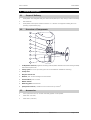
K&F�SONA�5
User's�Manual
Important�Information,
Please�Read�Before�Use!
KLING & FREITAG GmbH
Junkersstraße 14
D-30179 Hannover
TEL +49 (0) 511 96 99 70
FAX +49 (0) 511 67 37 94
www.kling-freitag.de
Revison 3.0
Released: 29.03.2010
User's manual
K&F SONA 5
Table of contents
1
Introduction
4
1.1
Symbols in User's Manual
4
1.2
Information about this User's Manual
4
2
Product�Description
5
2.1
Scope of Delivery
5
2.2
Overview of Components
5
2.3
Accessories
5
2.4
Required Tools
6
Safety�Instructions
6
3
3.1
Mounting the Speakers / Wall and Ceiling Installation
6
3.2
Notes for Mounting the Speakers
7
3.3
Preventing hearing damage
7
3.4
Protecting the Speakers / Operating Safety
7
4
Wall�and�Ceiling�Installation
8
5
Stand�Installation
11
6
Proper�Alignment�of�the�Loudspeakers
11
7
Operation�with�or�without�a�controller
12
8
Wiring
12
8.1
Terminal assignment
12
8.2
Wiring Diagrams
12
8.3
Wiring instructions
12
9
Notes�for�the�Version�with�'100�Volt'�Option
13
10
Operating�the�Speakers
13
11
Technical�Specifications
15
12
Measuring�diagrams
15
13
Dimensions
16
13.1
with swivel arm M (56mm) - (included)
16
13.2
with swivel arm M (32mm) - (Accessory)
17
13.3
with swivel arm M (109mm) - (Accessory)
18
14
Disposal
14.1
19
Regulations for Disposal
19
14.1.1
Germany
19
14.1.2
EU, Norway, Iceland, and Liechtenstein
19
14.1.3
All other Countries
19
KLING & FREITAG GMBH © 2009
Revision 3.0
Page 3 of 19
User's manual
1.
K&F SONA 5
Introduction
Thank you for your decision to buy a KLING & FREITAG sound system. To guarantee a trouble-free operating of the equipment and to allow your KLING & FREITAG SONA 5 system to achieve its full potential
please read the operating instructions carefully before use. With the purchase of a SONA 5 system, you
have acquired a large sound system with the highest possible quality and performance capabilities. As
the owner of a SONA 5 system, you now have a versatile and highly professional tool which, when
operated properly, is a true pleasure to use.
1.1
Symbols�in�User's�Manual
This symbol indicates the possibility of life-threatening danger and a health risk for persons. Not following
these instructions may result in serious health problems including potentially fatal injuries.
Warning
This symbol indicates a possibly dangerous situation. Not following these instructions may cause minor
injuries or cause property damage.
Caution
This symbol gives instructions for the proper use of the described products. Not following these instructions may cause malfunctions or property damage.
Important
This symbol indicates notes that help you to handle the described products easier.
Tip
1.2
Information�about�this�User's�Manual
© Kling & Freitag GmbH, 2008, all rights reserved.
All specifications in this manual are based on information available at the time of publishing for the
features and safety guidelines of the described products.
Technical specifications, measurements, weights and properties are not guaranteed.
The manufacturer reserves the right to make product alterations within legal provisions as well as changes
to improve product quality.
All�persons�who�use�the�speaker�system�must�have�this�guide�and�all�further�information�for
safe�operations�available�to�them�during�assembly,�disassembly,�and�use.The�speaker�system
may�neither�be�set�up�nor�used�until�this�manual�has�been�read,�understood�and�kept�readily
available�on�site.
We appreciate any input with suggestions and improvements for this manual. Please send this to us at
the following address:
[email protected] or to:
KLING & FREITAG GMBH Junkersstr.14 D-30179 Hannover.
Phone +49 (0) 511 96 99 70, Fax +49 (0) 511 67 37 94.
KLING & FREITAG GMBH © 2009
Revision 3.0
Page 4 of 19
User's manual
2.
K&F SONA 5
Product�Description
2.1
Scope�of�Delivery
•
Loudspeaker with integrated ball joint swivel arm M (56mm) for wall, ceiling or stand mountings
•
User's Manual
•
Loudspeakers with option 'Phoenix connector' or '100 Volt' are supplied including the corresponding 4-pole Phoenix plug.
2.2
Overview�of�Components
1
2
3
4
5
6
7
8
9
1.
Loudspeaker�enclosure, hightech moulding material (flame retardant class V0 according to UL94)
with textured paint finish
2.
Safety�eyelet for 5 mm quick link (quick link not included but available as accessory)
3.
Clamp�collar
4.
Ball�joint�swivel�arm
5.
Retainer, 5/8" inner threading for thread reducer
6.
Thread�reducer, 5/8" on M10
7.
Rubber�washer
8.
Mounting�plate with M10 bolt
9.
Quad�push�connector, suitable for wire cross section up to 4mm
2.3
2
Accessories
•
5 mm quick chain link. For use with the safety eyebolt on the speaker.
•
Swivel arm S (32 mm)
•
Swivel arm L (109 mm)
KLING & FREITAG GMBH © 2009
Revision 3.0
Page 5 of 19
User's manual
2.4
K&F SONA 5
Required�Tools
•
2.5 mm Allen head wrench
•
19 mm jaw spanner
•
Mounting accessories for installation on walls or ceilings
3.
3.1
Safety�Instructions
Mounting�the�Speakers�/�Wall�and�Ceiling�Installation
The speakers may only be mounted to wall and ceilings by qualified personnel.
The technicians responsible for assembling the speakers on site are responsible for the safe setup and
use of the speakers and guarantee this.
Warning
Never use signal cables or power cords for suspending, aligning or securing the systems.
Before carrying through ceiling and wall installations, it is essential to consider the load capacity of walls,
ceilings and panelling as well as the stability and type of the construction. If there is wall panelling, for
example, it is then necessary to examine the solidity of the wall and use the appropriate wall plugs.
Make sure to comply with the stipulated tightening torques.
If not otherwise stated in this manual, only original KLING & FREITAG parts may be used for mounting the
speakers. The use of other parts - in particular parts by other manufacturers - is not permitted in this case.
Ensure that all installation connections comply with the applicable safety guidelines and that the size
and strength are sufficient.
Ensure that all connections are secured against coming loose and that only authorized, statically tested
and correctly sized supports, mounting equipment, wire ropes and chains are used.
As a basic principle, you must visually inspect all components of the speaker before every use. If there are
signs of wear, cracks, or deformation, then you must replace the parts immediately. The visual inspection
also includes checking the screwed connections on supporting elements.
The information described here does not relieve the user of the duty to follow the given safety requirements and legal regulations.
Fixed�installations�(stationary):
•
For fixed installations without safety, always secure the retainer nut and the M10 thread of the
thread reducer to prevent loosening. ou can do so either by using the provided rubber washer or
– with longer threads – glue for securing screws.
Mobile�installations�(non-stationary):
•
Always secure the speaker with a second independent safety device to prevent falling.
•
To do so, use an approved safety rope with a 5 mm quick link on the safety eyebolt of the
speaker enclosure. You can get an appropriate quick link available as an accessory from Kling &
Freitag.
KLING & FREITAG GMBH © 2009
Revision 3.0
Page 6 of 19
User's manual
3.2
K&F SONA 5
Notes�for�Mounting�the�Speakers
Mount the speakers securely. To avoid injury or damage, always be sure to mount the speakers securely
so that they do not fall. Please note that speakers can move as a result of vibrations. To prevent them
from falling from their mounted position, they must be secured properly. When laying out the connecting
cables, make sure that nobody can trip.
Caution
The stability of stacked systems (also valid for the use of stands and distance rods!) is contingent upon
the following stability requirement:
Stacked� systems� may� not� fall� over� even� if� they� are� inclined� by� 10°� in� each� direction.� If� this
requirement�is�not�fulfilled,�then�it�is�necessary�to�take�steps�to�achieve�compliance.�Possible
measures� include� strapping� it� to� an� appropriate� base� structure� or� fastening� it� using� safety
straps.
3.3
Preventing�hearing�damage
Avoid beeing too close to operating speakers. This equipment is capable of delivering sound pressure
levels in excess of 90 dB/SPL, which may cause permanent hearing damage.
Caution
KLING & FREITAG GMBH © 2009
Revision 3.0
Page 7 of 19
User's manual
3.4
Important
K&F SONA 5
Protecting�the�Speakers�/�Operating�Safety
In general, audio signals should not be overdriven. This may be caused by mixing consoles, equalizers,
effect equipment, etc. and should be indicated on this equipment. When a power amplifier is overloaded
at the output (clipping), then the amplifier should activate a clipping warning signal. Power amplifiers
can also be overloaded at the input circuit without the amplifier signalling the clipping, i.e. when there is
not sufficient headroom in the input circuit. We, therefore, recommend turning up the power amplifiers
all the way and adjusting the level before the power amplifier in order to avoid overloading the input
circuit. In any case, the signal must be reduced as soon as it sounds unnaturally distorted.
Operations�without�CD�44�Controller:
•
To protect the speakers from being destroyed and to avoid fire hazard, they should only be operated with professional power amplifiers with a maximum rated output power of 200W@16Ω
(equiv. 400W@8Ω / equiv. 800W@4Ω).
•
If power amplifiers have power ratings lower than 100W@16Ohm, then it is imperative that the
amplifiers have clipping limiters. Alternately, you can also insert a clipping limiter before the amplifier.
•
To protect the loudspeaker from mechanical damage when high SPL is required a highpassfilter
of 24dB/oct. at 60Hz has to be inserted into the signal chain.
Operations�with�CD�44�Controller:
•
For optimal performance and operating safety of the SONA 5 speakers we recommend using
the system controller K&F CD 44.
•
When operating the loudspeaker with amplifers without clipping limiter and nominal amplifier
power less than 100W@8Ohm requires to set a Limit Reduction of 3dB for the K&F CD 44 controller. You can find more detailed information about this option in the K&F CD 44 hardware
manual.
•
The destruction of speakers and the risk of fire as a result of a very rare power amplifier or
speaker defect may not be avoided by the controller in any case.
For�damage�caused�by
•
overloading the speakers
•
using power amplifiers with other than the recommended maximum output power
we do not assume warranty and excludes liability for possible consequential damage.
The�following�signals�may�damage�the�speakers:
•
clipping power amplifiers
•
permanent high-level signals with high frequency and continuous noise from feedback.
•
permanently distorted high-level signals.
•
noises, which occur when the amplifier is on while equipment is being con-nected, disconnected
or switched on.
Do�not�install�devices�in�any�of�the�following�places:
•
where the devices are permanently exposed to direct sunlight.
•
where the devices are exposed to high moisture or rain.
•
where the devices are exposed to strong vibrations and dust.
Avoid�damage�caused�by�the�speakers'�magnetic�fields
Speakers are permanently surrounded by a magnetic field, even when they are not connected. Therefore,
during transport and placement of the speakers, it is important to ensure that there is a sufficient distance
between the speakers and magnetic data media and computer/video monitors (except flat panels).
KLING & FREITAG GMBH © 2009
Revision 3.0
Page 8 of 19
User's manual
4.
K&F SONA 5
Wall�and�Ceiling�Installation
Screw the mounting plate (A) through all 4 mounting holes onto the wall or ceiling. Choose fasteners that are suitable for the wall or ceiling material.
After installation, the mounting plate incl. speaker must be capable of carrying the 6-fold of its
own weight. Take suitable measures to prevent the
screw connection from loosening itself.
Ensure that the rubber washer (B) is on the bolt.
Screw the thread reducer (C) hand tight onto the
bolt of the mounting plate. Make sure the slit of the
thread reducer is facing the mounting plate. After
assembly the M10 bolt has to protrude from the
thread reducer.
As an alternative to the mounting plate, you can also mount the swivel arm with other suitable 10 mm
bolts.
If you screw the swivel arm onto another 10 mm bolt that is longer than that of the wall mount, the
rubber safety washer loses its function. In this case, if you were to install the speaker without an additional
safety, you would have to secure the thread of the 10 mm bolt and the thread of the connecting nut so
they do not loosen themselves (i.e. with glue for securing screws).
Warning
Loosen the Allen screws with a 2.5 mm Allen head
wrench.
Loosen one or two of the three Allen screws only.
This way you can avoid having to tighten an Allen
screw that got covered by the swivel arm while you
aligned the speaker.
Tip
Loosen this screw(s) just enough so that you can
move the swivel arm with some resistance. This will
simplify the final alignment of the speaker. This will
simplify the final alignment of the speaker.
KLING & FREITAG GMBH © 2009
Revision 3.0
Page 9 of 19
User's manual
K&F SONA 5
Screw the retainer nut (A) onto thread reducer (B)
using a 19 mm jaw spanner. While doing this, align
the swivel arm.
Now align the loudspeaker arm as desired, and
then re-tighten the Allen screws that you previously
loosened.
Tighten the screws enough so that the speaker reliably keeps its position. Using excessive force to
tighten the screws can result in irreparable destruction of the threads!
Important
KLING & FREITAG GMBH © 2009
Revision 3.0
Page 10 of 19
User's manual
5.
K&F SONA 5
Stand�Installation
The retainer nut of the swivel arm is equipped with a 5/8" thread into which a reducer with an inner
thread of M10 is screwed. You can exchange this thread reducer for a commercially available reducer
for microphone stands so you can mount the swivel arm onto a microphone stand. Depending on the
design of the stand, the thread reducer for microphone stands have a 3/8" or a 1/2" inner thread that
fit onto the thread bolts of the stands.
Exchange the provided 5/8" thread reducer with a
standard thread reduce for stands (A).
Screw the the thread reducer (A) onto the bolt of
the stand by hand. Make sure the slit of the thread
reducer is facing the stand.
Using a 19 mm jaw spanner, screw the retainer nut
onto the bolts of the stand.
To ensure that the speaker does not loosen and
cannot turn, you must screw the retainer nut tightly onto the knurled nut of the stand.
6.
Proper�Alignment�of�the�Loudspeakers
Please note that precisely targeted speaker systems can significantly improve the acoustic result. It is not
possible to make generalities about the alignment of specific systems because the room has a substantial
influence on the signal and the audible result.
As a rule, the mid- and high-transducers of loudspeakers should be mounted above the audience's face
value, so that the sound distribution cannot be shadowed.
In many cases it is advisable to mount a loudspeaker higher, so that the sound will be distributed throughout the room more evenly. Low standing systems result in a greater difference in volume between front
and back seats than higher standing systems.
To simulate the correct alignment of the speakers beforehand, there are various programs such as
‘Ease’ or ‘Ulysses’. The Kling & Freitag speaker system data is available for download on our website
www.kling-freitag.de.
KLING & FREITAG GMBH © 2009
Revision 3.0
Page 11 of 19
User's manual
7.
K&F SONA 5
Operation�with�or�without�a�controller
Operation�without�a�Controller
Important
The SONA 5 system is designed so that it can be operated passively without a controller directly on
a power amplifier. Follow the instructions in chapter "[Protecting the Speakers / Operating Safety]"
beginning on page 7.
•
For safe operation, they must only be operated with professional power amplifiers with a maximum rated output power of 200W@16Ω (equiv. 400W@8Ω or 800W@4Ω).
•
If power amplifiers have power ratings lower than 100W@16Ohm, then it is imperative that the
amplifiers have clipping limiters. Alternately, you can also insert a clipping limiter before the amplifier.
•
To protect the loudspeaker from mechanical damage when high SPL is required a highpassfilter
of 24dB/oct. at 60Hz has to be inserted into the signal chain.
Operation�with�a�Controller
When operating the loudspeaker with amplifers without clipping limiter and nominal amplifier power
less than 100W@8Ohm requires to set a Limit Reduction of 3dB for the K&F CD 44 controller. You can
find more detailed information about this option in the K&F CD 44 hardware manual.
8.
Wiring
Electrical current of loudspeaker signal may be hazardous for the human body.
Always make sure the connectors secured against touch when the equipment is in use.
Warning
Always fully insert bared wire ends into the push connector or the Phoenix plug such that bared parts
of wire can not be touched.
For speakers with Phoenix connector the bared wire ends have to be accurately screwed into the plugs.
8.1
Terminal�assignment
Clamp�connector
8.2
Option�'Phoenix�connectors'
Option�'100�Volt'�with�Phoenix
connectors
Wiring�Diagrams
You will find all necessary pin diagrams for operations with the CD 44 Controller in the User’s Manual
of the CD 44! This applies for use with and without the K&F Subwoofer.
KLING & FREITAG GMBH © 2009
Revision 3.0
Page 12 of 19
User's manual
8.3
K&F SONA 5
Wiring�instructions
•
Before connecting your SONA 5 system switch off all equipment and turn down all level controls.
•
Only use high-quality speaker cables with a sufficient wire gauge. The wire gauge depends on
the length of the speaker cable.
Minimum�Wire�Gauge�(mm²)
=�Required�Cable�Length�(m)�/�(2�x�Speaker�Impedance�(Ω))
•
For connections to the power amplifier inputs, please use 2-pin shielded microphone cable (balanced) with high-quality connectors.
•
Avoid ground loops.
•
Please pay attention to the pin assignments shown in this manual.
•
Make sure that the +/- polarity of the speakers at the amplifier is correct. When simultaneously
using power amplifiers from different manufacturers, be sure to use the correct specific pin configuration. It may be necessary to modify the pin configuration on the power amplifiers or on
the connectors leading to them.
•
Upon completing the wiring, ensure that the connected speaker channels are working in phase.
To do so, use i.e. a phase checker. A phase error can also be recognized when the connected
channels are used simultaneously. During simultaneous use the bass frequencies become notably
quieter or the mid-frequencies such as voices cannot be located.
•
If several loudspeakers are connected, the signal can be linked through from one loudspeaker to
the next. Please make sure that the total impedance of the loudspeakers R(Ω) is not lower than
the minimal impedance indicated on the power amplifier.
1/R1�+�1/R2�+�1/R3�+�...�=�1/Rtotal
Important
9.
Notes�for�the�Version�with�'100�Volt'�Option
Kling & Freitag speakers with '100V' option are fitted with high-quality transformers. This serves to
minimize loss of sound. Highly professional sound reinforcement results can be achieved using '100 Volt'
Kling & Freitag speakers.
Reasons�for�choosing�Speakers�with�100�Volt�Transformers:
•
Reduction in conduction loss.
•
Easy installation of a loudspeaker network due to simple parallel wiring. The sum of the output
power of the individual speakers (stated as VA = W) must not exceed the output power of the
100 Volt amplifier.
•
Speakers are galvanically isolated.
•
Speakers can be integrated into existing 100 Volt systems.
KLING & FREITAG GMBH © 2009
Revision 3.0
Page 13 of 19
User's manual
K&F SONA 5
10. Operating�the�Speakers
Important
•
Switch off all equipment and turn down all level controls of the mixing console and the power
amplifiers.
•
Wire your systems according to the instructions in this manual. SONA 5
•
Switch on the mixing console first, then the controller and the power amplifier. Always use the
before mentioned switching order. Otherwise switching noises may damage the sound system.
•
If there is interference, turn off all appliances in the reverse order and check all cable connections.
•
Successively turn up the individual power amplifier channels and send a signal with low volume
to the system. Check to see if the desired signals are applied to the intended speakers and make
sure there is no interference.
With�controller: The SIGNAL LEDs of the CD 44 Controller will light up if the output level is
higher than -45 dB. Your system should now be ready for operation.
•
Turning down the input level controls may not always prevent distortions in the input section
of the power amplifier, especially if this section has a relatively low headroom. A clipping signal
may not be displayed by the clipping indicator then! To prevent signal interruptions or damages
to the speakers, turn the level controls of the power amplifier to the maximum position, if possible. Set the output level of the mixing console or the controller to a level that doesn't overload
the power amplifiers or decrease the limiter threshold of the controller.
•
When turning off the system, the input controls for the power amplifiers should be turned
down first followed by the power switches of the amplifiers. After that, the other appliances can
be turned off.
KLING & FREITAG GMBH © 2009
Revision 3.0
Page 14 of 19
User's manual
K&F SONA 5
11. Technical�Specifications
Design
Passive 2-way bassreflex system
Frequency�range�-10�dB
80 Hz - 23 kHz
Frequency�range�+/-�3�dB
110 Hz - 22 kHz
Coverage�angles�nominal
120° x 90° (hor. x vert.)
Power�handling
100 watts (IEC 268-5)
SPL�(1W�/�1m)
89 dB SPL
Max.�SPL�(1m)
115 dB SPL
Components
5‘‘ low-mid chassis
1" Dome tweeter plus waveguide
Impedance�(nominal)
16 Ω
Connectors
Quad push connector (parallel)
Enclosure
high tech moulding synthetics
(flame retardant class V0 according to UL94),
safety eyelet for quick chain link,
ball joint swivel arm with mounting plate,
textured paint finish in black or white,
exchangeable front grille
Dimensions
140 x 230 x 170 mm
Weight
2,8 kg
Options
'100 Volt' with 10/20/40 VA transformer
and Phoenix connectors (3.4 kg),
'Phoenix connectoers' instead of clamp connectors,
'Special finish in RAL colours'
Accessories
5 mm quick chain link, certified,
'Swivel arm S (32 mm)',
'Swivel arm L (109 mm)'
12. Measuring�diagrams
KLING & FREITAG GMBH © 2009
Revision 3.0
Page 15 of 19
User's manual
K&F SONA 5
13. Dimensions
13.1
with�swivel�arm�M�(56mm)�-�(included)
56 mm / 2,218"
120 mm / 4,724"
230 mm / 9,055"
140,3 mm / 5,524"
9,9 mm / 0,390"
170 mm / 6,693"
2,5 mm / 0,098"
60 mm / 2,362"
212 mm / 8,348"
90
°
150,2 mm / 5,915"
262,7 mm / 10,343"
Ø 5,5 mm / Ø 0.217
277,1 mm / 10,908"
100 mm / 3,937"
3 4°
45 mm / 1,772"
KLING & FREITAG GMBH © 2009
Revision 3.0
Page 16 of 19
User's manual
13.2
K&F SONA 5
with�swivel�arm�M�(32mm)�-�(Accessory)
202 mm / 7,954"
230 mm / 9,052"
1 9°
266,5 mm / 10,491"
32 mm / 1,261"
KLING & FREITAG GMBH © 2009
45°
173,6 mm / 6,834"
200 mm / 7,865"
Revision 3.0
Page 17 of 19
User's manual
13.3
K&F SONA 5
with�swivel�arm�M�(109mm)�-�(Accessory)
279 mm / 10,980"
°
242,7 mm / 9,554"
90
9,9 mm / 0,390"
212 mm / 8,346"
109 mm / 4,288"
212 mm / 8,347"
90
°
203 mm / 7,998"
62,7 mm / 2,469"
KLING & FREITAG GMBH © 2009
Revision 3.0
Page 18 of 19
User's manual
K&F SONA 5
14. Disposal
14.1
Regulations�for�Disposal
14.1.1
Germany
It�is�not�allowed�to�dispose�of�used�electrical�equipment�as�domestic�waste.
Dispose�of�the�SONA�5�loudspeaker�at�public�collection�points�for�recycling!
The SONA 5 loudspeaker is a so called dual-use product intended for domestic and commercial use.
Therefore old SONA 5 loudspeakers can be disposed of in public collection/recycling points, contrary to
Kling & Freitag products which are limited to commercial use. Of course old SONA 5 loudspeakers can
be returned to us and KLING & FREITAG GmbH will take care of appropriate disposal.
Explanation
ElektroG is the enforcement of Directive 2002/95/EC, regulating, amonst others, the collection and recycling of electrical components and equipment.
From 03/24/2006 onwards KLING & FREITAG GmbH has thus labelled all products mentioned in the
WEEE with a sign with a crossed out waste bin and a white bar below. This sign indicates that the disposal
as domestic waste is prohibited and that the product has been put into circulation on 03/24/2006 at
the earliest.
KLING & FREITAG GmbH has been legally registered as a manufacturer with the German registration
office EAR. Our�WEEE�registration�number�is:�DE64110372.
14.1.2
EU,�Norway,�Iceland,�and�Liechtenstein
It�is�not�allowed�to�dispose�of�used�electrical�equipment�as�domestic�waste.
From 08/13/2005 onwards KLING & FREITAG GmbH has thus labelled all products for EU-Member countries as well as Norway, Iceland and Liechtenstein (except Germany) mentioned in the WEEE with a sign
with a crossed out waste bin and a white bar below. This sign indicates that the disposal on domestic
waste is prohibited and that the product has been put into circulation on 08/13/2005 at the earliest.
Unfortunately the European directive WEEE has been complied with implementing different national
provisions of law throughout all member countries, which makes it impossible for us to offer consistent
solutions for the disposal throughout Europe.
Responsible for complying with these provisions of law is the local distributor (importer) of each country.
For proper disposal of used products in accordance with these local provisions in the mentioned countries
of the European Union (except Germany) please ask your local dealer or the local authorities.
14.1.3
All�other�Countries
For proper disposal of used products in accordance with local provisions in other than the above mentioned countries please ask your local dealer or the local authorities.
KLING & FREITAG GMBH © 2009
Revision 3.0
Page 19 of 19