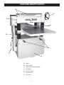
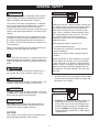
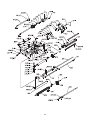
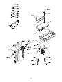
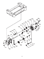
1
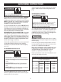
User Manual
Read and understand this manual before using machine.
20” PLANER
®
C
US
STEEL CITY TOOL WORKS
Model No.
40270
Manual Part No. OR71873
eel City Planer.
St
w
ne
ur
yo
ng
si
ha
rc
pu
THANK YOU for
d inspected with
an
,
ed
st
te
,
ed
gn
si
de
en
This planer has be
ed and mainus
ly
er
op
pr
n
he
W
d.
in
you, the customer, in m
years of trouble free
ith
w
u
yo
e
id
ov
pr
ill
w
tained, your planer
by one of the longest
ed
ck
ba
is
it
hy
w
is
ch
service, whi
the business.
machinery warranties in
oducts in the Steel
pr
y
an
m
of
e
on
st
ju
is
This planer
ry and is proof of
ne
hi
ac
m
ng
ki
or
dw
oo
w
City’s family of
satisfaction.
er
om
st
cu
l
ta
to
to
t
en
our commitm
cellence each and
ex
r
fo
ve
ri
st
to
ue
in
nt
co
At Steel City we
customer. For
r
ou
u,
yo
of
n
io
in
op
e
every day and value th
Tool Works, please
ity
C
l
ee
St
or
er
an
pl
ur
yo
comments about
tytoolworks.com .
ci
el
te
.s
w
w
w
at
te
si
eb
visit our w
2
TABLE OF CONTENTS
INTRODUCTION
SECTION 1
Warranty .................................................................................................................................................4
SECTION 2
Product Specifications ............................................................................................................................7
SECTION 3
Accessories and Attachments ................................................................................................................7
SECTION 4
Definition of Terms ..................................................................................................................................7
SECTION 5
Feature Identification ..............................................................................................................................8
SECTION 6
General Safety........................................................................................................................................9
SECTION 7
Product Safety ......................................................................................................................................11
SECTION 8
Electrical Requirements........................................................................................................................12
SECTION 9
Unpacking & Inventory..........................................................................................................................14
SECTION 10
Assembly ..............................................................................................................................................16
SECTION 11
Adjustments ..........................................................................................................................................18
SECTION 12
Operations ............................................................................................................................................27
SECTION 13
Maintenance .........................................................................................................................................29
SECTION 14
Troubleshooting ....................................................................................................................................30
SECTION 15
Parts List..........................................................................................................................................32-33
CHECK
PAGE
NUMBERS
INTRODUCTION
This user manual is intended for use by anyone working with this machine. It should be kept available
for immediate reference so that all operations can be performed with maximum efficiency and safety.
Do not attempt to perform maintenance or operate this machine until you have read and understand the
information contained in this manual.
This Planer is designed to process wood only. Any other use is forbidden. This machine is not to be
modified for any reasons.
The drawings, illustrations, photographs, and specifications in this user manual represent your machine
at time of print. However, changes may be made to your machine or this manual at any time with no
obligation to Steel City Tool Works.
3
WARRANTY
STEEL CITY TOOL WORKS
5 YEAR LIMITED WARRANTY
Steel City Tool Works, LLC (“SCTW”) warrants all “STEEL CITY TOOL WORKS” machinery to be
free of defects in workmanship and materials for a period of 5 years from the date of the original retail
purchase by the original owner. SCTW will repair or replace, at its expense and at its option, any
SCTW machine, machine part, or machine accessory which in normal use has proven to be defective,
provided that the customer returns the product, shipping prepaid, to an authorized service center with
proof of purchase and provides SCTW with a reasonable opportunity to verify the alleged defect by
inspection. This warranty does not apply to defects due directly or indirectly to misuse, abuse,
negligence, accidents, or lack of maintenance, or to repairs or alterations made or specifically authorized
by anyone other than SCTW. Normal wear components are also excluded under this coverage. Every
effort has been made to ensure that all SCTW machinery meets the highest quality and durability
standards. We reserve the right to change specifications at any time due to our commitment to
continuous improvement of the quality of our products.
EXCEPT AS SET FORTH ABOVE, SCTW MAKES NO EXPRESS OR IMPLIED REPRESENTATIONS OR WARRANTIES WITH RESPECT TO ITS MACHINERY, OR ITS CONDITION,
MERCHANTABILITY, OR FITNESS FOR ANY PARTICULAR PURPOSE OR USE. SCTW
FURNISHES THE ABOVE WARRANTIES IN LIEU OF ALL OTHER WARRANTIES, EXPRESS
OR IMPLIED, INCLUDING THE WARRANTIES OF MERCHANTABILITY AND FITNESS FOR A
PARTICULAR PURPOSE, WHICH ARE HEREBY SPECIFICALLY DISCLAIMED.
SCTW SHALL NOT BE LIABLE FOR ANY (A) SPECIAL, INDIRECT, INCIDENTAL, PUNITIVE
OR CONSEQUENTIAL DAMAGES, INCLUDING WITHOUT LIMITATION LOSS OF PROFITS,
ARISING FROM OR RELATED TO THIS WARRANTY, THE BREACH OF ANY AGREEMENT OR
WARRANTY, OR THE OPERATION OR USE OF ITS MACHINERY, INCLUDING WITHOUT
LIMITATION DAMAGES ARISING FROM DAMAGE TO FIXTURES, TOOLS, EQUIPMENT,
PARTS OR MATERIALS, DIRECT OR INDIRECT LOSS CAUSED BY ANY OTHER PARTY, LOSS
OF REVENUE OR PROFITS, FINANCING OR INTEREST CHARGES, AND CLAIMS BY ANY
THIRD PERSON, WHETHER OR NOT NOTICE OF SUCH POSSIBLE DAMAGES HAS BEEN
GIVEN TO SCTW; (B) DAMAGES OF ANY KIND FOR ANY DELAY BY OR FAILURE OF SCTW
TO PERFORM ITS OBLIGATIONS UNDER THIS AGREEMENT; OR (C) CLAIMS MADE A
SUBJECT OF A LEGAL PROCEEDING AGAINST SCTW MORE THAN ONE (1) YEAR AFTER
SUCH CAUSE OF ACTION FIRST AROSE.
The validity, construction and performance of this Warranty and any sale of machinery by SCTW shall
be governed by the laws of the Commonwealth of Pennsylvania, without regard to conflicts of laws provisions of any jurisdiction. Any action related in any way to any alleged or actual offer, acceptance or
sale by SCTW, or any claim related to the performance of any agreement including without limitation
this Warranty, shall take place in the federal or state courts in Allegheny County, Pennsylvania.
STEEL CITY TOOL WORKS
4
WARRANTY CARD
Name ________________________________________________
Street _______________________________________________
Apt. No. ______________________________________________
City _________________________ State ______ Zip __________
Phone Number_________________________________________
E-Mail ________________________________________________
The following information is given on a voluntary basis
and is strictly confidential.
Where did you purchase your STEEL CITY machine?
Store: ____________________________________________
City:______________________________________________
2.
How did you first learn of Steel City Tool Works?
___ Advertisement
___ Mail Order Catalog
___ Web Site
___ Friend
___ Local Store
Other_______________________
CUT HERE
3.
4.
5.
6.
7.
Which of the following magazines
___ American Woodworker
––– Cabinetmaker
___ Fine Homebuilding
___ Journal of Light Construction
___ Popular Mechanics
___ Popular Woodworking
___ WOOD
___ WOODEN Boat
___ Woodsmith
___ Woodworker
___ Workbench
What is your age group?
___ 20 to 29 years
___ 40 to 49 years
___ 60 to 69 years
9.
How many Steel City machines do you own? _____________
11. Which benchtop tools do you own? Check all that apply.
___ Belt Sander
___ Belt / Disc Sander
___ Drill Press
___ Band Saw
___ Grinder
___ Mini Jointer
___ Mini Lathe
___ Scroll Saw
___ Spindle / Belt Sander
Other______________________
do you subscribe to?
___ American How-To
___ Family Handyman
___ Fine Woodworking
___ Old House Journal
___ Popular Science
___ Today’s Homeowner
___ Woodcraft
___ Woodshop News
___ Woodwork
___ Woodworker’s Journal
Other_________________
12. Which portable / hand held power tools do you own?
Check all that apply.
___ Belt Sander
___ Biscuit Jointer
___ Dust Collector
___ Circular Saw
___ Detail Sander
___ Drill / Driver
___ Miter Saw
___ Orbital Sander
___ Palm Sander
___ Portable Thickness Planer
___ Saber Saw
___ Reciprocating Saw
___ Router
Other_______________________
13. What machines / accessories would you like to see added to the
STEEL CITY line?
____________________________________________________
____________________________________________________
Which of the following woodworking / remodeling shows do
you watch?
___ Backyard America ___ The American Woodworker
___ Home Time
___ The New Yankee Workshop
___ This Old House
___ Woodwright’s Shop
Other__________________________________________
What is your annual household
___ $20,000 to $29,999
___ $40,000 to $49,999
___ $60,000 to $69,999
___ $80,000 to $89,999
How would you rank your woodworking skills?
___ Simple
___ Intermediate
___ Advance
___ Master Craftsman
10. What stationary woodworking tools do you own?
Check all that apply.
___ Air Compressor
___ Band Saw
___ Drill Press
___ Drum Sander
___ Dust Collection
___ Horizontal Boring Machine
___ Jointer
___ Lathe
___ Mortiser
___ Panel Saw
___ Planer
___ Power Feeder
___ Radial Arm Saw
___ Shaper
___ Spindle Sander
___ Table Saw
___ Vacuum Veneer Press
___ Wide Belt Sander
Other____________________________________________
Product Description:_____________________________________
Model No.: ___________________________________________
Serial No. _____________________________________________
1.
8.
14. What new accessories would you like to see added?
____________________________________________________
____________________________________________________
income?
___ $30,000 to $39,999
___ $50,000 to $59,999
___ 70,000 to $79,999
___ $90,000 +
15. Do you think your purchase represents good value?
___Yes
___ No
16. Would you recommend STEEL CITY products to a friend?
___ Yes
___ No
___ 30 to 39 years
___ 50 to 59 years
___ 70 + years
17. Comments:
____________________________________________________
____________________________________________________
____________________________________________________
____________________________________________________
____________________________________________________
How long have you been a woodworker?
___ 0 to 2 years
___ 2 to 8 years
___ 8 to 20 years
___ over 20 years
5
FOLD ON DOTTED LINE
PLACE
STAMP
HERE
Steel City Tool Works
P.O. Box 10529
Murfreesboro, TN 37129
FOLD ON DOTTED LINE
6
PRODUCT SPECIFICATIONS
Capacities
Product Dimensions
Maximum stock width
20-in.
Footprint
22-1/2 x 28-1/2”
Maximum stock thickness
8-in.
Length
55-1/2”
Maximum depth-of-cut
1/8-in.
Width
37”
Minimum length of stock
7-in.
Height
40-3/4”
Feed Rate
16-20 FPM
Weight
795 lbs.
Cutterhead
Shipping Dimensions
Speed
5000 RPM
Number of Knives
4
Diameter
3-3/16”
Cuts Per Minute
20,000
Motor Specifications
Type
Induction
Horsepower
5HP
Amps
25
Voltage
230V
Phase
Single
Hertz
60
RPM’s
3450
Carton Type
Wooden Crate
Length
29-1/2”
Width
38-1/2”
Height
48”
Gross Weight
880 lbs.
ACCESSORIES AND ATTACHMENTS
There are a variety of accessories available for your Steel City Product. For more information on
any accessories associated with this and other machines, please contact your nearest Steel City
distributor, or visit our website at: www.steelcitytoolworks.com.
DEFINITION OF TERMS
Workpiece – The wood or lumber that you are working
on.
Chatter Marks – An uneven “washboard” type of cut
caused by incorrect chipbreaker settings.
Planing – Refers to the sizing of the lumber to a
desired thickness, while creating a level surface.
Chip Marks – Occurs when knives catch the chips and
drag them across the lumber being planed, caused by
exhaust blockage or improper chip deflector settings.
Snipe – Gouging that occurs at the end of a board.
Tear Out – Deep gouging caused by improper chipbreaker settings.
7
FEATURE IDENTIFICATION
B
C
A
D
G
E
F
A)
Switch
B)
Return Rollers
C)
Table Raise/Lower Handwheel
D)
Bed Rollers
E)
Lifting Handles
F)
Access Panel
G) Belt Guard
8
GENERAL SAFETY
!
!
WARNING
WARNING
TO AVOID serious injury and damage to the machine,
read and follow all Safety and Operating Instructions
before assembling and operating this machine.
This manual is not totally comprehensive. It does not
and can not convey every possible safety and operational problem which may arise while using this
machine. The manual will cover many of the basic and
specific safety procedures needed in an industrial environment.
Exposure to the dust created by power sanding, sawing, grinding, drilling and other construction activities
may cause serious and permanent respiratory or
other injury, including silicosis (a serious lung disease), cancer, and death. Avoid breathing the dust,
and avoid prolonged contact with dust. The dust
may contain chemicals known to the State of
California to cause cancer, birth defects or other
reproductive harm.
All federal and state laws and any regulations having
jurisdiction covering the safety requirements for use of
this machine take precedence over the statements in
this manual. Users of this machine must adhere to all
such regulations.
Some examples of these chemicals are:
• Lead from lead-based paints.
• Crystalline silica from bricks, cement and other
masonry products.
• Arsenic and chromium from chemically-treated
lumber.
Below is a list of symbols that are used to attract your
attention to possible dangerous conditions.
!
This is the safety alert symbol. It is used to alert you to
potential personal injury hazards. Obey all safety messages that follow this symbol to avoid possible injury or
death.
!
Always operate tool in well ventilated area and provide for proper dust removal. Use a dust collection
system along with an air filtration system whenever
possible. Always use properly fitting NIOSH/OSHA
approved respiratory protection appropriate for the
dust exposure, and wash exposed areas with soap
and water.
DANGER
Indicates an imminently hazardous situation which, if
not avoided, WILL result in death or serious injury.
!
1. To avoid serious injury and damage to the machine,
read the entire User Manual before assembly and
operation of this machine.
WARNING
Indicates a potentially hazardous situation which, if not
avoided, COULD result in death or serious injury.
!
CAUTION
!
WARNING
Indicates a potentially hazardous situation, if not avoided, MAY result in minor or moderate injury. It may also
be used to alert against unsafe practices.
2. ALWAYS wear eye protection. Any machine can
throw debris into the eyes during operations,
which could cause severe and permanent eye
damage. Everyday eyeglasses are NOT safety
glasses. ALWAYS wear Safety Goggles (that
comply with ANSI standard Z87.1) when operating power tools.
CAUTION
CAUTION used without the safety alert symbol indicates a potentially hazardous situation which, if not
avoided, may result in property damage.
NOTICE
This symbol is used to alert the user to useful information about proper operation of the machine.
9
!
11. DO NOT FORCE the machine to perform an operation for which it was not designed. It will do a safer
and higher quality job by only performing operations
for which the machine was intended.
WARNING
12. DO NOT stand on a machine. Serious injury could
result if it tips over or you accidentally contact any
moving part.
3. ALWAYS wear hearing protection. Plain cotton is
not an acceptable protective device. Hearing
equipment should comply with ANSI S3.19
Standards.
!
13. DO NOT store anything above or near the machine.
14. DO NOT operate any machine or tool if under the
influence of drugs or alcohol.
WARNING
15. EACH AND EVERY time, check for damaged parts
prior to using any machine. Carefully check all
guards to see that they operate properly, are not
damaged, and perform their intended functions.
Check for alignment, binding or breakage of all
moving parts. Any guard or other part that is damaged should be immediately repaired or replaced.
4. ALWAYS wear a NIOSH/OSHA approved dust
mask to prevent inhaling dangerous dust or airborne particles.
16. Ground all machines. If any machine is supplied
with a 3-prong plug, it must be plugged into a 3contact electrical receptacle. The third prong is
used to ground the tool and provide protection
against accidental electric shock. DO NOT remove
the third prong.
5. ALWAYS keep the work area clean, well lit, and
organized. DO NOT work in an area that has slippery floor surfaces from debris, grease, and wax.
6. ALWAYS unplug the machine from the electrical
receptacle when making adjustments, changing
parts or performing any maintenance.
17. Keep visitors and children away from any machine.
DO NOT permit people to be in the immediate work
area, especially when the machine is operating.
7. AVOID ACCIDENTAL STARTING. Make sure that
the power switch is in the “OFF” position before
plugging in the power cord to the electrical
receptacle.
!
18. KEEP protective guards in place and in working
order.
19. MAINTAIN your balance. DO NOT extend yourself
over the tool. Wear oil resistant rubber soled shoes.
Keep floor clear of debris, grease, and wax.
WARNING
20. MAINTAIN all machines with care. ALWAYS KEEP
machine clean and in good working order. KEEP all
blades and tool bits sharp.
8. AVOID a dangerous working environment. DO
NOT use electrical tools in a damp environment
or expose them to rain.
!
21. NEVER leave a machine running, unattended. Turn
the power switch to the OFF position. DO NOT
leave the machine until it has come to a complete
stop.
22. REMOVE ALL MAINTENANCE TOOLS from the
immediate area prior to turning the machine ON.
WARNING
23. SECURE all work. When it is possible, use clamps
or jigs to secure the workpiece. This is safer than
attempting to hold the workpiece with your hands.
9. CHILDPROOF THE WORKSHOP AREA by
removing switch keys, unplugging tools from the
electrical receptacles, and using padlocks.
24. STAY ALERT, watch what you are doing, and use
common sense when operating any machine. DO
NOT operate any machine tool while tired or under
the influence of drugs, alcohol, or medication. A
moment of inattention while operating power tools
may result in serious personal injury.
10. DO NOT use electrical tools in the presence of
flammable liquids or gasses.
10
25. USE ONLY recommended accessories. Use of
incorrect or improper accessories could cause serious injury to the operator and cause damage to the
machine. If in doubt, DO NOT use it.
3. Prevent electrical shock. Follow all electrical and
safety codes, including the National Electrical Code
(NEC) and the Occupational Safety and Health
Regulations (OSHA). All electrical connections and
wiring should be made by qualified personnel only.
26. THE USE of extension cords is not recommended
for 230V equipment. It is better to arrange the
placement of your equipment and the installed
wiring to eliminate the need for an extension cord.
If an extension cord is necessary, refer to the chart
in the GROUNDING INSTRUCTIONS section of
this manual to determine the minimum gauge for
the extension cord. The extension cord must also
contain a ground wire and plug pin.
!
WARNING
4. TO REDUCE the risk of electrical shock. DO
NOT use this machine outdoors. DO NOT
expose to rain. Store indoors in a dry area.
27. Wear proper clothing, DO NOT wear loose clothing,
gloves, neckties, or jewelry. These items can get
caught in the machine during operations and pull
the operator into the moving parts. Users must
wear a protective cover on their hair, if the hair is
long, to prevent it from contacting any moving parts.
5. STOP using this machine, if at any time you experience difficulties in performing any operation.
Contact your supervisor, instructor or machine service center immediately.
28. SAVE these instructions and refer to them frequently and use them to instruct other users.
6. Safety decals are on this machine to warn and
direct you to how to protector yourself or visitors
from personal injury. These decals MUST be maintained so that they are legible. REPLACE decals
that are not legible.
29. Information regarding the safe and proper operation
of this tool is also available from the following
sources:
Power Tool Institute
1300 Summer Avenue
Cleveland, OH 44115-2851
www.powertoolinstitute.org
7. DO NOT leave the unit plugged into the electrical
outlet. Unplug the unit from the outlet when not in
use and before servicing, performing maintenance
tasks, or cleaning.
National Safety Council
1121 Spring Lake Drive
Itasca, IL 60143-3201
8. ALWAYS turn the power switch “OFF” before
unplugging the planer.
American National Standards Institute
25 West 43rd Street, 4th floor
New York, NY 10036
www.ansi.org
!
ANSI 01.1 Safety Requirements for
Woodworking Machines, and the U.S. Department
of Labor regulations
www.osha.gov
WARNING
9. DO NOT handle the plug or planer with
wet hands.
10. USE only accessories as described in this manual.
USE accessories only recommended by Steel City.
PRODUCT SAFETY
1. Serious personal injury may occur if normal safety
precautions are overlooked or ignored. Accidents
are frequently caused by lack of familiarity or failure
to pay attention. Obtain advice from supervisor,
instructor, or another qualified individual who is
familiar with this machine and its operations.
11. DO NOT pull the planer by the power cord. NEVER
allow the power cord to come in contact with sharp
edges, hot surfaces, oil or grease.
2. Every work area is different. Always consider safety first, as it applies to your work area. Use this
machine with respect and caution. Failure to do so
could result in serious personal injury and damage
to the machine.
13. REPLACE a damaged cord immediately. DO NOT
use a damaged cord or plug. If the planer is not
operating properly, or has been damaged, left outdoors or has been in contact with water.
12. DO NOT unplug the planer by pulling on the power
cord. ALWAYS grasp the plug, not the cord.
14. DO NOT use the planer as a toy. DO NOT use near
or around children.
11
15. ENSURE that the machine sits firmly on the floor
before using. If the machine wobbles or is unstable,
correct the problem by using shims or blocks prior
to operation.
22. INSPECT all stock before planing, ensuring that
there are no foreign objects embedded in the wood,
loose knots, or knots that may become loose during
operation.
16. This machine is designed to process WOOD ONLY.
!
!
WARNING
WARNING
23. DO NOT attempt to remove jams until power is
disconnected and all moving parts have come to
a complete stop.
17. NEVER position fingers or thumbs near the
infeed roller.
24. MAKE SURE that there is adequate operating
space on both the infeed and outfeed sides of the
planer before operating.
18. Long pieces of stock should ALWAYS be supported
with some type of fixture.
19. DO NOT operate planer with dull or damaged
blades.
25. DO NOT attempt to plane wood that is less than
7” long or less than 1/8-inch thick.
20. MAKE CERTAIN that the planer is properly adjusted prior to use.
21. DO NOT try and remove excessive amounts of
wood in one single pass.
ELECTRICAL REQUIREMENTS
!
WARNING
DO NOT connect the machine to the power source
before you have completed the set up process. DO
NOT connect the machine to the power source until
instructed to do so.
TO PREVENT electrical shock, follow all electrical and
safety codes, including the National Electrical Code
(NEC) and the Occupational Safety and Health
Regulations (OSHA). All electrical connections and
wiring should be made by qualified personnel only.
The switch provided with your planer is designed for
230V single phase use only. The switch has a power
cord with no plug attached. There are many different
configurations for 230 V outlets. A UL/CSA approved
plug that matches the configuration of your 230V outlet
must be installed before you can operate this tool.
TO REDUCE the risk of electrical shock, DO NOT use
machine outdoors. DO NOT expose to rain. Store
indoors in a dry area.
12
GROUNDING INSTRUCTIONS
!
A machine with a 230 volt plug should only be connected to an outlet having the same configuration as the
plug.
WARNING
EXTENSION CORDS
This machine MUST BE GROUNDED while in use to
protect the operator from electric shock.
!
In the event of a malfunction or breakdown, GROUNDING provides the path of least resistance for electric
current and reduces the risk of electric shock. The plug
MUST be plugged into a matching electrical receptacle
that is properly installed and grounded in accordance
with ALL local codes and ordinances.
WARNING
To reduce the risk of fire or electrical shock, use the
proper gauge of extension cord. When using an
extension cord, be sure to use one heavy enough to
carry the current your machine will draw.
If a plug is provided with your machine DO NOT modify
the plug. If it will not fit your electrical receptacle, have
a qualified electrician install the proper connections to
meet all electrical codes local and state. All connections
must also adhere to all of OSHA mandates.
The smaller the gauge-number, the larger the diameter
of the extension cord is. If in doubt of the proper size of
an extension cord, use a shorter and thicker cord. An
undersized cord will cause a drop in line voltage resulting in a loss of power and overheating.
IMPROPER ELECTRICAL CONNECTION of the equipment-grounding conductor can result in risk of electric
shock. The conductor with the green insulation (with or
without yellow stripes) is the equipment-grounding conductor. DO NOT connect the equipment-grounding conductor to a live terminal if repair or replacement of the
electric cord or plug is necessary.
!
CAUTION
USE ONLY a 3-wire extension cord that has a 3-prong
grounding plug and a 3-pole receptacle that accepts the
machine’s plug.
Check with a qualified electrician or service personnel if
you do not completely understand the grounding
instructions, or if you are not sure the tool is properly
grounded.
If you are using an extension cord outdoors, be sure it
is marked with the suffix “W-A” (“W” in Canada) to indicate that it is acceptable for outdoor use.
PLUGS/RECEPTACLES
Make certain the extension cord is properly sized, and
in good electrical condition. Always replace a worn or
damaged extension cord immediately or have it
repaired by a qualified person before using it.
!
WARNING
Protect your extension cords from sharp objects, excessive heat, and damp or wet areas.
MINIMUM RECOMMENDED GAUGE FOR EXTENSION CORDS (AWG)
• Electrocution or fire could result if this machine is
not grounded properly or if the electrical configuration does not comply with local and state electrical
codes.
230 VOLT OPERATION ONLY
• MAKE CERTAIN the machine is disconnected
from power source before starting any electrical
work.
• MAKE SURE the circuit breaker does not exceed
the rating of the plug and receptacle.
The motor supplied with your machine is a 230 volt,
60 hertz, single phase motor. Never connect the green
or ground wire to a live terminal
13
25’ LONG
50’ LONG
100’ LONG
0 to 6 Amps
16 AWG
16 AWG
14 AWG
6 to 8 Amps
16 AWG
16 AWG
12 AWG
8 to 12 Amps
14 AWG
14 AWG
10 AWG
12 to 15 Amps
12 AWG
12 AWG
10 AWG
15 to 20 Amps
10 AWG
10 AWG
Not
recommended
UNPACKING & INVENTORY
!
off with a soft cloth. This may need redone several
times before all of the protective coatings are removed
completely.
WARNING
• The machine is heavy; a forklift or overhead lift are
required to lift the machine.
After cleaning, apply a good quality paste wax to any
unpainted surfaces. Make sure to buff out the wax
before assembly.
• Use a safety strap to avoid tip over when lifting
machine.
Compare the items to inventory figures; verify that all
items are accounted for before discarding the shipping
box.
Check shipping carton and machine for damage before
unpackaging. Carefully remove packaging materials,
parts and machine from shipping carton. Always check
for and remove protective shipping materials around
motors and moving parts. Lay out all parts on a clean
work surface.
!
WARNING
If any parts are missing, do not attempt to plug in the
power cord and turn “ON” the machine. The machine
should only be turned “ON” after all the parts have been
obtained and installed correctly. For missing parts,
contact Steel City at 1-877-SC4-TOOL.
Remove any protective materials and coatings from all
of the parts and the planer. The protective coatings can
be removed by spraying WD-40 on them and wiping it
A
B
A)
Dust Port
B)
Extension Wings
14
C
D
E
G
H
P
I
Q
L
J
M
K
N
O
R
S
T
(C) Handwheel
(L) 6mm Allen Wrench
(D) Handle
(M) 5mm Allen Wrench
(E) Lock Knobs
(N) 4mm Allen Wrench
(G) 10mm Hex Nut
(O) 3mm Allen Wrench
(H) 10mm Flat Washer
(P) M8 x 25mm Hex Head Screws
(I)
(Q) M8 x 20mm Set Screws
Key
(J) 12-14mm Open End Wrench
(R) M6 Round Head Screws
(K) 8-10mm Open End Wrench
(S) M6 Flat Washer
(T) Knife Setting Jig
15
ASSEMBLY
Before beginning assembly, take note of the following
precautions and suggestions
!
Fig. 1
CAUTION
FLOOR
This tool distributes a large amount of weight over a
small area. Most commercial floors are appropriate for
this unit, however, in residential use, flooring may need
added reinforcement to accommodate the weight of the
machine and operator.
WORKING CLEARANCES
Take into consideration the size of the material to be
processed, space for auxiliary stands, work benches,
etc. before setting up this machine. Make sure that you
allow enough space for your machine to operate freely.
A
HANDWHEEL
OUTLET PLACEMENT
The purpose of the handwheel is for raising and lowering the planer table
Outlets should be located close enough to the machine
so that the power cord or extension cord is not in an
area where it would cause a tripping hazard. Be sure to
observe all electrical codes if installing new circuits and
or outlets.
!
1. Locate the handwheel shaft at the front right corner
of the planer.
2. Insert the key into the keyway on the handle shaft.
3. Line up the notch in the handwheel with the key
and slide the handwheel onto the handle shaft.
WARNING
4. Slide the direction scale over the shaft, making sure
it rests against the center face of the handwheel.
1. DO NOT assemble the Planer until you are sure the
tool is not plugged in.
5. Secure the handwheel using one 10mm hex nut
and one 10mm flat washer provided. SEE FIG 2.
2. DO NOT assemble the Planer until you are sure the
power switch is in the OFF position
6. Screw handle into the threaded hole on the handwheel.
3. For your own safety, DO NOT connect the machine
to the power source until the machine is completely
assembled and you read and understand the entire
User Manual.
!
Fig. 2
WARNING
This planer is a very heavy piece of equipment.
To assist with moving the unit, this Planer contains lifting handles (A) that slide out from the
base of the planer head. SEE FIG 1. These
handles can be used as lifting points using a
forklift or overhead lift. Attempting to lift this unit
without the proper equipment or adequate assistance could result in a serious injury.
16
EXTENSION TABLES
DUST PORT
The extension tables support the workpiece as it enters
and exits the planer.
This planer features a 5-in Dust Port for use with a dust
collection system. If this planer is not to be hooked up
to a dust collection system, DO NOT attach the dust
port.
1. To mount the extension tables, thread three
M8 x 20mm set screws into the bottom holes of the
extension table. Only screw them in about 1/3 of
the way for now.
1. Unbolt the upper cover from the planer to allow
access to the screw holes.
2. Using three M8 x 25mm hex head mounting bolts,
mount one extension table to the main table.
SEE FIG 3.
2. To attach the dust port, mount the port under the
upper cover on the planer.
3. Line up the 3 holes on the top of the dust chute
with the 3 holes on the upper cover and fasten with
three M6 round head screws, and three M6 flat
washers. SEE FIG 5.
Fig. 3
4. Use three M6 round head screws and three M6 flat
washers and fasten the dust port to the body of the
planer.
5. Rebolt the upper cover to the planer.
Fig. 5
3. Place a straight edge on the main table so that it
lies flat on the table and extends out over the
extension table. SEE FIG 4.
Fig. 4
4. Adjust the three set screws until edge of the extension table that is the furthest away from the main
table is even with the straight edge. Please note
that it may take several combinations of loosening
and/or tightening the set screws and mounting bolts
to get the extension table level with the main table.
5.
Repeat steps 1-4 to attach the other extension
table to the other side of the main table.
17
Fig. 6
KNIFE SETTING JIG
The knife setting jig provides a convenient way to make
setting the knives quick and simple.
1. To assemble the knife setting jig, snap one of the e
clips (B) over the notch on one end of the knife setting rod (A).
2. Slide both of the knife setting jig brackets (C) onto
the rod.
3. Snap on the other e clip to the opposite end of the
rod. SEE FIG 6.
!
CAUTION
Planer knives are extremely sharp. Please use extra
caution when your hands are near the blades.
ADJUSTMENTS
Some of the adjustments covered in this section have
already been made at the factory. It is still a good idea
to familiarize yourself with all of the following procedures so that you have a solid understanding of the
planers operation.
2. Turn the handwheel clockwise to raise the table so
that the block barely touches the left side of the
body of the cutterhead. NOTE: Make sure that the
block is actually touching the body of the cutterhead
and not the knives. SEE FIG 7.
TABLE PARALLELISM ADJUSTMENT
3. Slide the block to the right taking note of any gaps
between the top of the block and the bottom of the
cutterhead body. Measure any of these gaps with a
feeler gauge.
To make adjustments to the table, it is necessary to
make a gauge block.
When constructing this block, be sure to use a hardwood such as oak or maple. DO NOT use standard
2 x 4 material. A diagram for this block is located near
the end of the manual.
4. When moving the block from left to right, if the
block wedges tightly between the cutterhead and
the table, repeat steps 2 and 3, but start from the
right side of the cutterhead body and slide to the
block to the left.
NOTICE: A substitute for this gauge block would be to
use a magnetic dial indicator. Anywhere it calls for use
of the gauge block in this section, you may substitute
with the dial indicator.
!
Fig. 7
WARNING
DO NOT make adjustments while the planer is running. Make certain that the switch is in the off position and that the machine is disconnected from the
power source.
!
CAUTION
Planer knives are extremely sharp. Please use extra
caution when your hands are near the blades.
1. Having the table parallel to the cutterhead is essential for planing stock perfectly square. Check this by
placing the gauge block that you have constructed
under the left end of the cutterhead.
18
5. Referring back to your measurements with the
feeler gauge, if the gap difference from one side
to the other is .004 or less, no adjustment will be
necessary.
CHAIN TENSION
To adjust Chain Tension:
1. Remove the access panel (A) on the stand.
SEE FIG 8A.
If the gap is greater than .004, but less than .016,
proceed to step 6.
Fig. 8A
If the gap is greater than .016, refer to the ADJUSTING CHAIN DRIVE section in the ADJUSTMENTS
section of the manual.
6. For gap differences between .005 and .016, determine which side of the table needs to be raised to
fix the gap.
7. Locate the two cap screws (A) in the table casting
for each of the columns. SEE FIG 8.
Fig. 8
A
A
2. Loosen the two hex head bolts (B) that fasten the
idler sprocket (C) to the base and move the idler
sprocket until excess slack in the chain has been
eliminated. SEE FIG 8B.
8. Loosen both sets of screws for each column on the
side that needs adjusted.
Fig. 8B
9. Pull up or push down on the table in the direction
that it needs to move, hold in position and retighten
the screws.
10. Repeat these steps until the variance is .004 or less.
CHAIN ADJUSTMENTS
The chain drive in your planer transfers movement from
the hand wheel driven column to the three other support columns. The chain drive may require an adjustment to remove slack as the chain stretches over time,
or as part of table leveling procedures.
!
B
WARNING
3. Retighten the two hex head bolts.
MAKE CERTAIN THE MACHINE IS DISCONNECTED FROM THE POWER SOURCE.
4. Replace access panel.
19
C
D
ADJUSTING CHAIN DRIVE
KNIFE INSPECTION
Notice: The following steps should only be done
AFTER you have gone through the TABLE PARALELLISM ADJUSTMENT section of this manual and the
measurements you attained from that section are
greater than .016
!
!
CAUTION
Planer knives are extremely sharp. Please use extra
caution when your hands are near the blades.
The Planer knives are set at the factory using jack
screws. Springs are also included with your planer
which may be used instead of the jack screws, depending on your preference. These springs are installed
beneath the knives.
You can leave the springs in place as it will not affect
the adjustments if they are not removed.
If you prefer to use the spring adjustment method, you
will need to remove each knife, remove the jack screws,
leave the two springs under each knife and replace the
knife. Follow the steps below if using the spring adjustment method.
WARNING
MAKE CERTAIN THE MACHINE IS DISCONNECTED FROM THE POWER SOURCE.
1. Remove the panel (A) to gain access to the chain
drive assembly. SEE FIG 8A, page 19.
2. Loosen two hex head bolts (B) that fasten the idler
sprocket (C) to the base until you can turn each
corner sprocket (D) independently. One of the
corner sprockets is shown in Fig 8B. SEE FIG 8B,
page 19.
!
WARNING
MAKE CERTAIN THE MACHINE IS DISCONNECTED FROM THE POWER SOURCE.
Notice: If the chain drive is loosened too much, it will
fall off all of the sprockets. Replacing a chain that has
come off the sprockets is a very tedious process. Make
sure to loosen the idler pulley just enough to allow you
to be able to turn the corner sprockets.
1. Remove the dust port and upper cover and cutterhead guard to expose the top of the cutterhead.
SEE FIG 9.
3. Each tooth on a corner sprocket represents .016 of
vertical movement as it turns.
Fig. 9
4. Whichever end of the table is too high, turn the
sprockets at that end of the table clockwise to lower
the table. For example if the back end of the table
is too high, the back two sprockets would need to
be rotated clockwise to lower the back side of the
table. If the right end of the table is too high, the
right two sprockets would be rotated clockwise to
lower the right side, etc.
Notice: Make certain, as you turn the sprockets, to
keep an accurate tooth count to ensure that the table is
lowered equally on a specific side.
5. Recheck Table Parallelism using your gauge block.
Once the tolerance is less than .016, replace
access cover and refer back to the TABLE PARALELLISM ADJUSTMENT section in the ADJUSTMENT section of this manual.
2. Remove the belt guard. Turn the cutterhead (using
the pulley) until the first knife is top dead center.
3. Using the knife setting gauge, check the knife
height. The jig should set with both feet on the
cutterhead. SEE FIG 10, page 21. If the knife is
properly adjusted, the contact point at the center of
the gauge should just touch the tip of the knife. If
the knife does not make contact, or if the knife is
high enough to cause the legs of the gauge not to
set on the cutterhead, the knives will need adjusted.
Be sure to inspect all 4 knives in the same manner.
20
Fig. 10
KNIFE ADJUSTMENT
The knives are locked in the cutterhead with wedge
type gibs and gib bolts. Springs located under the
knives assist in setting the knife height. Jack screws
under the knives allow fine tuning to help out in the setting process.
1. MAKE CERTAIN THE MACHINE IS DISCONNECTED FROM THE POWER SOURCE.
2. Remove the upper cover to expose the cutterhead.
3. Loosen the gib bolts until the knife is loose in the
slot. The gib bolts turn clockwise to loosen and
counterclockwise to tighten. SEE FIG 12.
Fig. 12
The planer knives will need to be adjusted periodically
and ultimately will need to be removed to be sharpened. Adjustments should be as precise as possible
with tolerances within .002 -.003. This will help prolong
the sharpness of the knife edges. Improperly adjusted
knives can cause an imbalance condition in the cutterhead and shorten bearing life, as well as produce substandard results.
Gib
Bolt
4. Loosen the gib bolts by turning them clockwise until
the knife is loose in the slot.
Knife
5. Carefully remove the knife.
6. Unscrew the jack screws completely from the
threaded hole and remove.
Spring
7. Be sure that there is one spring in each of the two
holes in the bottom of the knife slot. SEE FIG 11.
NOTICE: The springs DO NOT go into the threaded
hole where the jack screws were installed.
4. Place the knife setting jig over the knife on the
cutterhead as shown in Fig. 13, page 22. The feet
of the jig should be securely planted on the cutterhead, making sure the gauge rod remains parallel
to the cutterhead. SEE FIG. 13 ON PAGE 22.
Fig. 11
5. Lower the jack screws as low as possible.
6.
Maintain a steady pressure on the knife setting jig
while retightening the gib bolts. The springs in the
cutterhead will push up on the knife allowing for
proper alignment of the knives.
7.
Once gib bolts are tightened, raise jack screws
until they just touch the bottom of the knife. You
should feel resistance when the jack screw touches
the bottom of the knife.
NOTICE: When making adjustments to the planer
knives, all four knives must be adjusted the same.
DO NOT adjust one knife without adjusting the
others as this can result in knife damage, poor
performance and possible injury to the operator.
21
5. Using a .040 feeler gauge between the gauge block
and the cutterhead, raise the table until the knife
just touches the feeler gauge.
Fig. 13
6. Lock the table using the table lock knobs.
7. Remove your feeler gauge and slide the gauge
block under one side of the chip breaker (D). The
chip breaker should just touch the top of the gauge
block.
8. Slide the gauge block to the opposite side of the
chip breaker, checking it the same way.
9. If any adjustment is necessary, loosen the locknuts
(E) and turn the setscrews (F). Stop turning when
the chipbreaker just touches the top of the gauge
block. SEE FIG 17.
Fig. 17
CHIP BREAKER
The chip breaker is located on the top side of the planer
and it extends down around the front of the cutterhead.
The purpose of the chip breaker is to prevent deep
gouging, also known as tear-out, as the knives do their
job. It works by breaking up the woodchips as they are
being cut by the knives. The chip breaker also deflects
and shoots out the woodchips away from the surface of
the board and out the planer.
!
H
H
G
G
E
WARNING
F
DO NOT make adjustments while the planer is
running. Make certain that the switch is in the off
position and that the machine is disconnected from
the power source.
F
1. Remove the upper cover and dust port, and lower
the table.
10. Retighten both locknuts and replace cover and dust
hood.
2. Make sure that the knives are properly adjusted.
PRESSURE BAR
3. Place the gauge block (A) on the table (B) directly
under the cutterhead (C). SEE FIG 16.
The pressure bar, like the chipbreaker, controls lumber
as it passes under the cutterhead. The pressure bar
helps to keep the lumber from lifting after it has been
planed. Incorrect positioning of the pressure bar can
result in a number of undesirable results such as snipe
or chatter marks. Setting the pressure bar too low can
also place excess load on the motor. To adjust the
pressure bar:
4. Rotate the cutterhead until one of the knives are at
its lowest point.
Fig. 16
D
C
!
WARNING
MAKE CERTAIN THE MACHINE IS DISCONNECTED FROM THE POWER SOURCE.
1. Remove top cover and dust port.
2. Loosen both locknuts (G). SEE FIG 17.
A
3. Place Gauge block under the center of the pressure
bar and adjust both of the setscrews (H) until the
pressure bar just touches the tip of the block.
4. Once the bar is set, retighten both of the locknuts
and replace top cover and dust port.
B
22
Fig. 19
FEED ROLLER HEIGHT
The infeed and outfeed rollers are responsible for
moving the workpiece through the machine and pressing the workpiece flat against the main table.
!
WARNING
MAKE CERTAIN THE MACHINE IS DISCONNECTED FROM THE POWER SOURCE
D
1. Lower the table so the gauge block (A) fits under
one side of the infeed roller (B).
E
2. Raise the table until the gauge block just barely
touches one side of the infeed roller. SEE FIG 18.
Fig. 18
C
B
9. Loosen the roller adjustment check nuts (D) and
turn the roller height set screws (E) to change the
height of the roller. SEE FIG 19.
10. When the roller is set in the correct position, retighten the check nuts from step 9.
11. Recheck roller height and repeat steps 8-10 if
necessary.
FEED ROLLER PRESSURE
Infeed and outfeed roller pressure is an important
aspect of any planer. When the workpiece is fed
through the planer, the correct amount of pressure
will help ensure that the board does not slip (too little
pressure) or does not jam (too much pressure).
A
3. Push the gauge block through so that it is under the
edge of one of the knives.
NOTICE: Excessive pressure may damage workpiece
It’s important to note that different lumber will require
varying amounts of pressure, so you may have to
experiment with different settings. While some rough
cut lumber will go through the planer with little trouble at
one pressure setting, other pieces may have some
more difficulty.
4. Turn the cutterhead (C) by hand using the pulley
until one of the knives are in its lowest position.
5. Using a feeler gauge, check the clearance between
the top of the gauge block and the edge of the
knife. Clearance should be .040.
NOTICE: Adjusting the roller pressure does not affect
height.
6. Repeat steps 1-5 for the opposite side of the roller.
7. Repeat this same process for the outfeed roller. If
any adjustment is necessary continue on to step 8.
!
8. Remove the gear box cover to access the roller
adjustments on the drive chain side on the planer.
One socket head cap screw holds the drive chain
cover in place.
WARNING
MAKE CERTAIN THE MACHINE IS DISCONNECTED FROM THE POWER SOURCE.
1. Before adjusting roller pressure, ensure that the
knives and feed rollers are set correctly.
NOTE: There are two metal guard plates bolted to the
backside of the gear box cover. It may be necessary to
remove one of these guards in order to remove the
gear box cover.
2. Unscrew the four large pressure set screws (A and
B) on the top of the planer body. SEE FIG 20.
23
5. Using a wrench, turn the eccentric shafts to adjust
the roller height up or down as shown in FIG 21.
Fig. 20
Fig. 21
B
A
3. Remove the springs that are in the holes left by the
set screws and check for any dirt or grit, cleaning
off any dirt and replace springs.
4. Screw the three regular pressure set screws (A)
back in until they are flush with the top of the head
casting.
6. Repeat steps 1-5 until clearance is .002 to .005.
7. Retighten all set screws.
5. Screw in the light pressure set screw (B) until it is
about 1/4” above the head casting. The reason this
screw is not tightened as much as the other three is
that the feed chain helps apply the needed tension
to this side of the outfeed roller.
8. Spin rollers by hand to ensure that they move
freely.
6. Tightening the set screws down further will
INCREASE roller pressure, while backing them off
will DECREASE roller pressure.
CHIP DEFLECTOR
The chip deflector (A) is the plastic plate under the top
cover that keeps woodchips from falling onto the
outfeed roller. SEE FIG. 22.
BED ROLLERS
!
The bed rollers aid the movement of the workpiece
through the planer. The height of these rollers will vary
depending on the types of wood. For rough stock, the
rollers should be set slightly higher to keep the lumber
from dragging along the bed. For smooth lumber, the
rollers should be set just above the surface of the table.
!
WARNING
MAKE CERTAIN THE MACHINE IS DISCONNECTED FROM THE POWER SOURCE
1. The beveled edge of the deflector should be about
1/8”-1/4” from the knife edge. Check this by carefully rotating the cutterhead by hand to gauge the
distance between the chip deflector and the knives.
WARNING
MAKE CERTAIN THE MACHINE IS DISCONNECTED FROM THE POWER SOURCE.
!
CAUTION
1. Lay a straight edge across both of the table rollers.
If the chip deflector is set too close to the knives, the
rotating cutterhead may pull it in and destroy it.
2. Using a feeler gauge, measure the clearance
between the bottom of the straight edge and the
table. Make sure to measure in several places.
3. If measurement is between .002 and .005, the
clearance is acceptable. If you do not have a
measurement of .002 to .005 go to step 4.
2. If adjustment is necessary, loosen the three deflector mounting bolts.
4. Loosen the set screws located on both sides of
each roller.
24
Fig. 22
!
WARNING
DO NOT apply any oil or other lubricant to the antikickback fingers as this can attract dust and restrict
the free movement of the fingers. This could result
in damage to the planer, the workpiece, or even
serious injury to the operator or others in the work
area. DO NOT attempt to use the planer if the antikickback fingers are not functioning properly.
A
PULLEYS
!
WARNING
MAKE CERTAIN THE MACHINE IS DISCONNECTED FROM THE POWER SOURCE
3. Make sure the beveled edge of the deflector faces
the cutterhead.
1. To inspect pulleys, place a steel ruler or other type
of straight edge across the pulleys to check the
alignment. If the ruler crosses them evenly, the
pulleys are aligned correctly. SEE FIG 24.
4. Move the deflector until the edge is approximately
1/8” - 1/4” from the edge of the knives.
5. Push down on the deflector with a wooden stick
and spin the cutterhead by hand to ensure that it
does not contact the knives.
!
Fig. 24
CAUTION
Planer knives are extremely sharp. Please use extra
caution when your hands are near the blades.
6. Retighten the chip deflector mounting bolts and
remount the upper cover and dust port to the planer.
ANTI- KICKBACK FINGERS
Anti-kickback fingers (A) are an added safety feature on
this planer. They are suspended from a rod that hangs
across the front of the cutterhead casting. These fingers
should be inspected regularly, ensuring that they swing
freely and easily. SEE FIG 23.
Fig. 23
2. If pulleys are out of alignment, loosen the bolts that
hold the motor to the motor mount bracket.
A
3. Adjust the motor position until the pulleys are
aligned.
4. Retighten all bolts.
25
BELTS
!
GEAR BOX
The gearbox is located just behind the handwheel on
the right side of the planer. The gearbox transfers
power from the belt driven cutterhead to the power feed
rollers. It has a two speed transmission that is controlled by a lever on the right side of the planer. When
it is engaged, the power feed rollers will move the workpiece through the planer at either 16 ft/ min or 20 ft/min.
The center position on the lever is neutral.
WARNING
MAKE CERTAIN THE MACHINE IS DISCONNECTED FROM THE POWER SOURCE
1. If the belt is too loose, remove the belt guard using
the two threaded knobs.
2. To check belt tension, squeeze the Belts at their
midpoint with moderate finger pressure. You should
be able to deflect each belt no more than 3/4”.
1. To inspect gearbox, loosen the socket head cap
screw on the gearbox cover.
3. Remove the panel at the back of the machine stand
to access the motor assembly.
2. Pull the cover off the roll pins that hold it in place
4. The motor pivots on a platform suspended at one
end by two threaded adjustment bolts. Adjust the
locknuts (A) up or down the shafts until the desired
belt deflection is achieved. SEE FIG 25.
NOTE: There are two metal guard plates bolted to the
backside of the gear box cover. It may be necessary to
remove one of these guards in order to remove the
gear box cover.
Fig. 25
3. Inspect the bolts that hold the sprockets in place
4. Check the drive chains to make sure that the retaining clips are in place. SEE FIG 26.
Fig. 26
A
26
OPERATIONS
!
Fig. 27
WARNING
This planer is a very powerful woodworking
machine designed and built for professional use.
Because of this, the machine should be operated
with significant care and caution. Failure to do
so could result in severe injury to the operator or
others in the work area. Be sure to read this
entire manual for all safety precautions before
operating this machine.
PLANER SUMMARY
1. Examine all lumber carefully for defects such as
twisting, warping, knots, splits, crossgrain, and
foreign objects such as nails, staples, etc before
running it through the planer. If you are unsure
about the quality of the wood, DO NOT USE IT!!!
!
2. Use the full width of the planer. Alternate between
the left, right, and center when feeding lumber
through the planer. Doing so will help extend the
life of your blades.
CAUTION
The feed rate should be set ONLY while planer is
running, and BEFORE the workpiece is inserted into
the planer. DO NOT attempt to change speeds
after the cutting operation has started.
3. Be sure to clean off all glue of joined boards before
planing.
4. This planer is designed for natural wood only. DO
NOT use any composites, laminates, particle board,
plywood, or plastics in the planer.
DEPTH LIMITER
This planer is equipped with a depth limiter (A), located
at the bottom of the cutterhead casting, which controls
the maximum depth of cut to 1/8”. SEE FIG 28. With
the limiter installed, you will not be able to cut more
than 1/8” in a single pass. While it is possible to plane
as much as 1/8” at a time, it is not recommended.
Taking more shallow passes will improve the quality of
your work as well as extend the life of your planer.
5. ALWAYS plane with the grain of the wood. NEVER
feed end cut or end grained lumber through the
planer.
6. When making multiple passes through the planer
on long stock, use the stock return rollers located
on top of the machine to move the workpiece over
to the infeed side of the table.
Fig. 28
7. Wood that has a high moisture content (greater
than 20%) or wood exposed to rain or snow will
plane poorly and cause excessive wear to the
knives, and accelerate rust and corrosion.
8. This manual does not cover every aspect of planing
wood. You should research alternative publications
for more specific requirements. This type of follow
up will help provide with a better understanding of
the planing process as well as alert you to several
precautions to take that may or may not be listed in
this manual.
A
POWER FEED
The power feed feature two different feed rates,
16 FPM (feet per minute) and 20 FPM. WHILE THE
MACHINE IS RUNNING, moving the knob one direction
produces the 16FPM setting while moving the other
direction produces the 20FPM setting. There is also a
central position for the knob, which is neutral.
SEE FIG 27.
NOTICE: To avoid mechanical damage to the planer, do
not remove the depth limiter.
27
TABLE LOCKS
TRIAL RUN
Before attempting to adjust the table height, loosen the
two black knobs (A) on the right side of the table. Once
the table height is adjusted correctly, retighten the two
knobs. SEE FIG 29.
Once all the assembly is complete and the adjustments
are complete, it’s time for a test run.
Fig. 29
2. Press the start button. Keep your hand near the
switch, ready to shut the machine down quickly in
case anything does not sound right or if there
appears to be a problem.
1. Turn on the power supply
3. The planer should run smoothly with little to no
vibration or rubbing noises. If any strange noise is
noticed, shut down machine and recheck all adjustments.
!
WARNING
Do not attempt to make adjustments while the
machine is running. Make certain the machine is
disconnected from the power source and the
machine has come to a complete stop.
!
WARNING
A
ALWAYS wear eye protection. Any machine can
throw debris into the eyes during operations which
could cause severe and permanent eye damage.
Everyday eyeglasses are NOT safety glasses.
ALWAYS wear Safety Goggles (that comply with
ANSI standard Z87.1) when operating power tools.
HANDWHEEL
Turning the handwheel clockwise will raise the main
table while turning it counterclockwise will lower the
table. Crank the handwheel to raise or lower the table
according to the desired workpiece thickness.
Fig. 30
28
MAINTENANCE
GENERAL
GEAR BOX
Make a habit of inspecting your planer each time you
use it. Check the following conditions and repair or
replace as necessary.
1. Worn Switch
2. Damaged cords and/or plugs
3. Damaged belts
4. Loose bolts
5. Any other condition that could hamper the safe
operation of the machine
Gear box oil should be drained after the first 20 hours
of operation. Replace with 80W-90 gear oil for use in
room temperature shops and 50W gear oil for unheated
winter shops. Inspect levels periodically and change
yearly for occasional use, more frequently with heavy use.
To inspect oil level,
1. Using the short end of a hex wrench, dip the
wrench inside the fill hole and rotate so the long
end of the wrench is parallel to the table.
2. Remove the wrench. If the end of the hex wrench
is coated with oil, then the gearbox level is okay.
TABLE
3. If the end of the hex wrench is not coated with oil,
then you need to add more oil.
The table and other non-painted surfaces on the planer
should be protected against rust. Be sure to wipe the
table clean after every use. This will help prevent moisture from the wood condensing on the bare metal table.
It is also a good idea to use a paste wax on the bare
metal surfaces. This will help keep moisture from the
table and hence help keep it from rusting. Over time,
some rust may still develop on the table. To get rid of
the rust, use some WD-40 and a fine steel wool.
4. Remove gear box cover. For information on removing gear box cover, refer to the gear box section in
the ADJUSTMENTS section of this manual, page 26.
5. Replace fill plug when finished.
DRIVE CHAIN
The drive chain should be inspected and lubricated
monthly using a general purpose grease.
KNIVES
FEED ROLLER
Make sure that your knives are sharp and properly
adjusted before each knives. The sharpness and proper setting of the knives is essential to good planing.
Refer back to the section on knives in this manual for
detailed instructions .
The infeed / outfeed pressure setscrews double as the
lubrication ports for the rollers. Add 1-2 drops of light
machine oil to all ports before every use. Daily lubrication of feed rollers is CRUCIAL to the operation of the
planer. Lubricate before start up.
LUBRICATION
LEAD SCREWS AND COLUMNS
The four columns should be lubricated weekly with a
light oil. The four lead screws (A) should be lubricated
with general purpose grease once a month
BEARINGS
Your planer is equipped with factory sealed bearings
requiring no lubrication during its lifetime. If the bearing
should fail, the planer will produce a pronounced rumble that will get even louder under load. If it is allowed
to get worse, overheating can occur and eventually the
bearing can seize up, possibly causing damage to
other parts of the machine.
The lead screws and columns (B) should be wiped of
any grease and dust build up at least once a week.
They should be lubricated with light machine oil.
SEE FIG 31.
Fig. 31
WORM GEAR
The worm gear should be inspected monthly and
lubricated with a white lithium grease as needed.
Remove the worm gear box to inspect. See parts
diagram for location.
A
CHAIN
The table height adjustment chain should be inspected
regularly and lubricated as needed. Lubricate with a
general purpose grease.
B
29
TROUBLESHOOTING GUIDE
This section covers the most common processing problems encountered in planing and what to do about them. Do
not make any adjustments until planer is unplugged and moving parts have come to a complete stop. See the section
on Wood Characteristics for additional troubleshooting information.
PROBLEM
LIKELY CAUSE(S)
SOLUTION
Motor will not start.
1. Low voltage.
1. Check power line for proper voltage.
2. Open circuit in motor or loose connections.
2. Inspect all lead connections on motor for loose or open
connections.
1. Short circuit in line cord or plug.
1. Inspect cord or plug for damaged insulation and shorted
wires.
2. Short circuit in motor or loose connections.
2. Inspect all connections on motor for loose or shorted
terminals or worn insulation.
3. Incorrect fuses or circuit breakers in power line.
3. Install correct fuses or circuit breakers.
1. Motor overloaded.
1. Reduce load on motor.
2. Air circulation through the motor restricted.
2. Clean out motor to provide normal air circulation.
1. Short circuit in motor or loose connections.
1. Inspect connections on motor for loose or shorted terminals
or worn insulation.
2. Low voltage.
2. Correct the low voltage conditions.
3. Incorrect fuses or circuit breakers in power
line.
3. Install correct fuses or circuit breakers.
4. Motor overloaded.
4. Reduce load on motor.
Machine slows when
operating.
1. Feed rate too fast.
1. Change speed.
2. Depth of cut too great.
2. Reduce depth of cut.
Loud, repetitious
noise coming from
machine.
1. Pulley setscrews or keys are missing or
loose.
1. Inspect keys and setscrews. Replace or tighten if necessary.
Motor will not start;
fuses or circuit
breakers blow.
Motor overheats.
Motor stalls (resulting
in blown fuses or
tripped circuit).
Machine is loud
when cutting.
Overheats or bogs
down in the cut.
2. Motor fan is hitting the cover.
2. Tighten fan or shim cover.
3. V-belt is defective.
3. Replace V-belt.
1. Excessive depth of cut.
1. Decrease depth of cut.
2. Knives are dull.
2. Sharpen knives.
Infeed roller marks
are left on the
workpiece.
Depth of cut too shallow.
Increase depth of cut.
Outfeed roller marks
are left on right side
of workpiece.
Too much spring tension on feed roller.
Refer to Feed Roller Pressure section for adjustment.
Cannot control
snipe.
Long or heavy board sags as it enters and
exits.
Lift up on unsupported end of board as it enters and exits
cutterhead.
Machine howls on
startup.
Chip deflector too close to the cutterhead.
Move chip deflector back 1/8” to 1/4” from the cutterhead.
Table moves down
while cutting.
1. Knives dull.
1. Replace knives.
2. Table locking knobs are loose.
2. Tighten table locking knobs.
30
31
N NOTES N
32
PARTS
KEY
NO.
PART
NO .
DE S C R IP T IO N
1A
O R 70406
MO T O R ( 5 H P, 2 2 0 -2 4 0 V, 1 P H )
1B
O R 70355
MO T O R S P E C P L AT E
KEY
NO .
PART
NO .
1
14
OR94007
1
15
O R 90280
Q T Y.
DE S C R IP T IO N
13mm x 28mm x 3mm FLATWASHER
M1 2 H E X N U T
Q T Y.
4
4
1C
O R 94269
C A P A C IT O R
1
16
O R 71814
MO T O R A D J U S T ME N T S H A F T A S S Y
2
2
OR94045
STRAIN RELIEF
1
17
OR71815
SUPPOR T SHAFT
2
3
O R 90219
5 mm x 5 mm x 3 0 mm K E Y
1
18
O R 70310
S P E C . P L AT E
1
4
O R 7 1 8 11
MO T O R P U L L E Y
1
19
O R 94271
HE X S C R E W
4
5
OR9031 1
M8 FLA T W A S H E R
1
20
OR94007
13mm x 28mm x 3mm FLAT WASHER
8
6
O R 93917
M8 x 2 0 mm H E X H E A D S C R E W
1
21
O R 90280
M1 2 H E X N U T
4
7
O R 71812
S PAC E R
1
22
O R 71816
MO T O R B A S E
1
8
OR94270
M8 x 12mm HEX SOC HD SET SCREW
3
23
O R 71817
C OVE R
2
9
O R 71813
MO T O R MO U N T IN G P L AT E
1
24
O R 90306
M6 x 2 0 mm P A N H E A D S C R E W
8
10
O R 91501
M8 H E X N U T
4
25
O R 94045
S T R A IN R E L IE F
1
11
OR9031 1
M8 FLA T W A S H E R
4
26
OR90308
M8 x 30mm HEX HEAD SCREW
2
12
O R 93891
M8 x 4 0 mm H E X H E A D S C R E W
4
27
*
Start Capacitor 600MFD, 125 VAC
1
13
OR91499
M8 FLA T W A S H E R
4
33
34
KEY
NO.
PART
NO.
QTY.
KEY
NO.
PART
NO.
200
OR71818
201
OR91752
EXTENSION WING
2
233
OR94273
M5 x 10mm PAN HEAD SELF- TAPPING SCREW
32
M8 x 25mm HEX HEAD SCREW
6
234
OR71828
MOUNTING RING
16
202
OR91821
203
OR70949
M8 x 20mm SOC HD SET SCR
6
235
OR71829
MAIN COLUMN
1
COLUMN LOCK NUT
2
236
OR71830
COLUMN SHAFT
3
204
205
OR71819
COLUMN LOCK SHAFT
2
237
OR71831
COLUMN
3
OR94272
M8 x 16mm SOC HD CAP SCREW
8
238
OR71832
BASE
1
207
OR71820
BED CASTING
1
239
OR93524
M10 x 12mm SOC HD SET SCREW
8
208
OR70946
COLUMN LOCK BUSHING
2
240
OR94274
CHAIN
1
209
OR94015
KNOB
2
241
OR70958
CHAIN TENSIONER BRACKET
1
210
OR71821
BED ROLLER
2
242
OR70957
SPROCKET SHAFT
1
212
OR71822
ECCENTRIC SHAFT
4
243
OR71833
SPROCKET
1
213
OR94055
BALL BEARING (6201Z)
4
244
OR94024
RETAINING RING
1
214
OR90306
M6 x 12mm SOC HD SET SCREW
4
245
OR90311
M8 FLAT WASHER
2
225
OR94041
RETAINING RING
1
246
OR91752
M8 x 25mm HEX HEAD SCREW
2
226
OR71823
WORM
1
247
OR94021
BALL BEARING (6202ZZ)
4
227
OR94018
RETAINING RING
1
248
OR94022
RETAINING RING
4
DESCRIPTION
DESCRIPTION
QTY.
228
OR71824
BUSHING
1
249
OR71834
SPROCKET
4
229
OR71825
COLUMN LOCK NUT
4
250
OR90230
M10 FLAT WASHER
4
230
OR94019
4mm x 4mm x 10mm KEY
5
251
OR90228
M10 HEX NUT
4
231
OR71826
ELEVATING SCREW
1
252
OR94275
E - RING
4
232
OR71827
DUST SLEEVE
8
253
OR71835
SHAFT
4
35
36
KEY
NO.
PART
NO.
QTY.
KEY
NO.
PART
NO.
300
OR93899
M6 x 16mm SOC HEAD CAP SCREW
9
347
OR71844
CHIP GASKET
1
301
OR71836
302
OR71837
ROLLER BRACKET
3
348
OR71849
SPRING PLATE
1
ROLLER
2
349
OR71850
CUTTERHEAD CASTING
1
303
304
OR70965
HANDLE
1
350
OR93524
M10 x 12mm SOC HD SET SCREW
8
OR90280
M12 HEX NUT
1
351
OR91499
M8 FLAT WASHER
4
305
OR94007
13mm x 28mm x 3mm FLAT WASHER
1
352
OR90333
M6 x 12mm HEX HEAD SCREW
4
306
OR71838
HAND WHEEL
1
353
OR71851
SIDE COVER GUARD
1
307
OR71839
SPACER
1
356
OR94044
E-RING
2
308
OR94276
RETAINING RING
1
357
OR70955
SPACER
56
309
OR94055
BALL BEARING (6201Z)
1
358
OR70996
ANTI-KICK BACK FINGER
55
310
OR94019
4mm x 4mm x 10mm KEY
1
359
OR71852
ANTI-KICKBACK SHAFT
1
311
OR71840
ELEVATING WORM SHAFT
1
360
OR71853
KNIFE
4
312
OR94277
M6 x 50mm SOC HD CAP SCREW
3
361
OR71854
CUTTERHEAD
1
313
OR71841
ELEVATING SCREW GEARBOX
1
362
OR90863
M5 x 12mm PAN HEAD SCREW
8
314
OR71001
GEAR BOX OPERATION LABEL
1
363
OR94056
SPRING
8
315
OR92923
M8 x 40mm SOC HEAD CAP SCREW
1
364
OR94035
8mm x 8mm x 36mm KEY
1
316
OR71842
SIDE COVER
1
365
OR93522
BALL BEARING (6206-2NSE)
1
DESCRIPTION
DESCRIPTION
QTY.
317
OR94028
SPRING PIN
2
366
OR71855
KNIFE LOCKING BAR
318
OR71843
SIDE COVER GUARD
1
367
OR94033
HEX SCREW
4
319
OR94029
M6 x 12mm HEX HEAD SERRATED SCREW
4
368
OR94038
M6 x 16mm HEX HEAD SCREW
1
320
OR70974
CHAIN TENSIONER SHAFT
1
369
OR94052
6.2mm x 20mm x 3mm FLAT WASHER
1
321
OR70973
CHAIN TENSIONER
1
370
OR70985
OUTFEED ROLLER SPROCKET
1
322
OR70975
SHAFT
1
371
OR94037
5mm x 5mm x 22mm KEY
1
323
OR70976
BRACKET
1
372
OR71856
OUTFEED ROLLER
1
324
OR90311
M8 FLAT WASHER
1
373
OR94035
SPRING
4
20
325
OR94031
SPRING
1
374
OR70987
BUSHING
4
326
OR70978
SPRING HOOK PLATE
1
375
OR70988
RETAINER PLATE
4
327
OR94032
M6 x 10mm SOC HD CAP SCREW
2
376
OR93951
M6 x 16mm SOC HD SET SCREW
4
328
OR94278
M6 x 16mm HEX HEAD SERRATED SCREW
5
377
OR90235
M6 HEX NUT
4
329
OR71845
CHIP DEFLECTOR
1
378
OR94281
M8 x 18mm HEX HEAD SCREW
4
330
OR94030
SCREW
4
380
OR71857
SUPPORT SHAFT
1
331
OR90249
M8 x 50mm SOC HD CAP SCREW
4
381
OR90280
M12 HEX NUT
1
332
OR93951
M6 x 16mm SOC HD SET SCREW
2
382
OR71858
CHIP BREAKER SHAFT
1
333
OR71846
SCALE ASSY CONST. OF REF 334 TO 337
1
383
OR90306
M6 x 12mm SOC HD SET SCREW
2
334
OR71847
SCALE
1
384
OR90235
M6 HEX NUT
2
335
OR94279
M5 x 10mm SOC HD CAP SCREW
1
385
OR94041
RETAINING RING
1
336
OR71848
POINTER
1
386
OR71859
PRESSURE BAR MOUNT
2
337
OR90320
M6 x 12mm PAN HEAD SCREW
2
387
OR93917
M8 x 20mm HEX HEAD SCREW
2
338
OR94029
M6 x 12mm HEX HEAD SERRATED SCREW
6
388
OR91663
M8 LOCK WASHER
2
339
OR70982
SPRING PLATE
3
389
OR71860
PRESSURE BAR
1
340
OR93823
RIVET
4
390
OR94037
5mm x 5mm x 22mm KEY
1
341
OR70484
NAME PLATE
1
391
OR71861
CHIP BREAKER
1
342
OR90507
M5 x 8mm PAN HEAD SCREW
2
392
OR70992
INFEED ROLLER SPROCKET
1
343
OR70983
LIMIT PLATE
1
393
OR94052
6.2mm x 20mm x 3mm FLAT WASHER
1
344
OR94280
M6 x 20mm HEX SOC HD SET SCREW
2
394
OR94038
M6 x 16mm HEX HEAD SCREW
1
345
OR90235
M6 HEX NUT
2
395
OR94282
CHAIN
1
346
OR71848
ADJUSTING SHAFT
2
396
OR71862
INFEED ROLLER
1
37
38
KEY
NO.
PART
NO.
QTY.
KEY
NO.
PART
NO.
401
OR90290
402
OR90291
3MM WRENCH
1
425
OR90311
M8 FLAT WASHER
1
4MM WRENCH
1
426
OR91752
M8 x 25mm HEX HEAD SCREW
1
403
404
OR91728
5MM WRENCH
1
427
OR71010
BELT GUARD MOUNT
2
OR91729
6MM WRENCH
1
428
OR71011
BELT
3
405
OR90908
8MM / 10MM OPEN END WRENCH
1
429
OR71012
BELT GUARD FRONT
1
406
OR93975
12MM / 14MM OPEN END WRENCH
1
430
OR94050
KNOB
2
407
OR94283
OPEN END WRENCH
1
435
OR71866
POWER SWITCH
1
408
OR90333
M6 x 12mm HEX HEAD SCREW
6
436
OR94046
10 - 24 x 1 3/4 PAN HD SCREW
2
409
OR90059
M8 FLAT WASHER
6
437
OR71867
SWITCH MOUNT
1
410
OR71863
DUST CHUTE
1
438
OR90374
10 - 24 HEX NUT
2
411
OR71864
DUST HOOD
1
439
OR90053
#10 EXTERNAL TOOTH WASHER
2
412
OR93372
M6 x 12mm SOC HD CAP SCREW
6
440
OR93372
M6 x 12mm SOC HD CAP SCREW
2
413
OR90059
M8 FLAT WASHER
6
441
OR94045
STRAIN RELIEF
2
414
OR71865
CHIP GASKET
1
442
OR90304
M20 FLAT WASHER
4
DESCRIPTION
DESCRIPTION
QTY.
420
OR71008
CUTTERHEAD PULLEY
1
443
OR71000
MOTOR CORD
1
421
OR90616
5/16 - 18 HEX NUT
2
444
OR71868
POWER CORD
1
422
OR90311
M8 FLATWASHER
2
446
OR71006
KNIFE SETTING GAGE SHAFT
1
423
OR71009
BELT GUARD REAR
1
447
OR94049
E-RING
4
424
OR94029
M6 x 12mm HEX HEAD SERRATED SCREW
4
448
OR71869
KNIFE SETTING GUAGE
2
39
40
KEY
NO.
PART
NO.
501
OR71870
GEAR BOX ASSY CONST. OF REF 502 TO 547
502
OR71871
CHAIN & TENSIONER ASSY
CONST. OF REF 503 TO 511
1
DESCRIPTION
QTY.
KEY
NO.
PART
NO.
1
524
OR92734
BALL BEARING (6201)
1
525
OR93936
M6 x 25mm SOC HD CAP SCREW
1
526
OR71019
GEAR
1
527
OR90366
BALL BEARING (6204ZZ)
1
528
OR93372
M6 x 12mm SOC HD CAP SCREW
1
529
OR94052
6.2mm x 20mm x 3mm FLAT WASHER
1
530
OR94053
OIL SEAL
1
531
OR94054
PLUG
1
532
OR71020
GEARBOX
1
533
OR94054
PLUG
1
534
OR71021
GEARBOX GASKET
1
535
OR94055
BALL BEARING (6201Z)
1
536
OR71022
GEAR ASSEMBLY
1
537
OR71023
SHAFT
1
503
OR70974
CHAIN TENSIONER SHAFT
1
504
OR70973
CHAIN TENSIONER
1
505
OR71872
TENSIONER BRACKET
1
506
OR94284
M6 x 35mm SOC HEAD CAP SCREW
1
507
OR90059
M6 FLAT WASHER
1
508
OR71026
SPROCKET
1
509
OR94285
CHAIN
1
510
OR94038
M6 x 16mm HEX HEAD SCREW
1
511
OR94052
6.2mm x 20mm x 3mm FLAT WASHER
1
512
OR94062
KNOB
1
513
OR94064
O-RING
1
514
OR71027
SHAFT
1
515
OR71028
SHIFTING CLAW
1
516
OR94029
M6 x 12mm HEX HEAD SERRATED SCREW
1
517
OR93936
M6 x 25mm SOC HD CAP SCREW
6
518
OR71015
PIN
2
519
OR71016
GEARBOX COVER
1
520
OR92734
BALL BEARING (6201)
1
521
OR94051
5mm x 5mm x 12mm KEY
1
522
OR71017
SHAFT
1
523
OR71018
GEAR
1
41
DESCRIPTION
QTY.
538
OR94060
6mm x 6mm x 40mm KEY
1
539
OR94056
SPRING
1
540
OR94057
STEEL BALL
1
541
OR94058
OIL SEAL
1
542
OR94059
BALL BEARING (6204Z)
1
543
OR94055
BALL BEARING (6201Z)
1
544
OR71024
GEAR
1
545
OR94061
5mm x 5mm x 10mm KEY
1
546
OR71025
SHAFT
1
547
OR94055
BALL BEARING (6201Z)
1
OR71873
Manual (not shown)
1
OR71874
Manual French (not shown)
1
OR71875
Manual Spanish (not shown)
1
N NOTES N
42
STEEL CITY
TOOL WORKS
www.steelcitytoolworks.com
1-877-SC4-TOOL
(1-877-724-8665)
N
5 Year Warranty
43