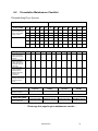
1
MDB Series Dehumidifying Dryers Central Drying Systems Operation and Installation Manual Electrical Edition 50, 100, 150, 255 CFM (85, 170, 255, 380 M3/hr) Part Number: 882.02900.00 Bulletin Number: DRY1-690.00 Effective: August 2014 Use in Conjunction with: MDB Mechanical Manual: 882.99969.00 CDS Mechanical Manual: 882.02569.00 (If Applicable) Write Down Your Serial Numbers Here For Future Reference: _________________________ _________________________ _________________________ _________________________ _________________________ _________________________ We are committed to a continuing program of product improvement. Specifications, appearance, and dimensions described in this manual are subject to change without notice. DCN No. ____________ © Copyright 2014 All rights reserved. ii Shipping Info Unpacking and Inspection You should inspect the MDB dehumidifying dryer for possible shipping damage. Thoroughly check the equipment for any damage that might have occurred in transit, such as broken or loose wiring and components, loose hardware and mounting screws, etc. In the Event of Shipping Damage According to the contract terms and conditions of the Carrier, the responsibility of the Shipper ends at the time and place of shipment. Notify the transportation company’s local agent if you discover damage. Hold the damaged goods and packing material for the examining agent’s inspection. Do not return any goods before the transportation company’s inspection and authorization. File a claim with the transportation company. Substantiate the claim by referring to the agent’s report. A certified copy of our invoice is available upon request. The original Bill of Lading is attached to our original invoice. If the shipment was prepaid, write us for a receipted transportation bill. Advise customer service regarding your wish for assistance and to obtain an RMA (return material authorization) number. If the Shipment is Not Complete Check the packing list as back-ordered items are noted on the packing list. You should have: þ MDB Dehumidifying Dryer þ Bill of lading þ Packing list þ Operating and Installation packet þ Electrical schematic and panel layout drawings þ Component instruction manuals Re-inspect the container and packing material to see if you missed any smaller items during unpacking. If the Shipment is Not Correct If the shipment is not what you ordered, contact the shipping department immediately. For immediate assistance, please contact the correct facility located in the technical assistance section of this manual. Have the order number and item number available. Hold the items until you receive shipping instructions. iii Returns Do not return any damaged or incorrect items until you receive shipping instructions from the shipping department. Credit Returns Prior to the return of any material authorization must be given by the manufacturer. A RMA number will be assigned for the equipment to be returned. Reason for requesting the return must be given. ALL returned material purchased from the manufacturer returned is subject to 15% ($75.00 minimum) restocking charge. ALL returns are to be shipped prepaid. The invoice number and date or purchase order number and date must be supplied. No credit will be issued for material that is not within the manufacturer’s warranty period and/or in new and unused condition, suitable for resale. Warranty Returns Prior to the return of any material, authorization must be given by the manufacturer. A RMA number will be assigned for the equipment to be returned. Reason for requesting the return must be given. All returns are to be shipped prepaid. The invoice number and date or purchase order number and date must be supplied. After inspecting the material, a replacement or credit will be given, at the manufacturer’s discretion. If the item is found to be defective in materials or workmanship, and it was manufactured by our company, purchased components are covered under their specific warranty terms. iv Table of Contents CHAPTER 1: SAFETY .............................................................. VII 1-1 1-2 1-3 How to Use This Manual ............................................................................................ vii Safety Symbols Used in this Manual .................................................................... vii Warnings and Precautions .......................................................................................... ix Responsibility .............................................................................................................. x General Responsibility .......................................................................................... x Operator Responsibility ......................................................................................... x Maintenance Responsibility ................................................................................. xii Reporting a Safety Defect .................................................................................... xii CHAPTER 2: GENERAL INFORMATION ................................ 13 2-1 2-2 2-3 2-4 Models Covered in This Manual................................................................................ 13 Necessary Documents .............................................................................................. 13 Control Features ....................................................................................................... 13 Safety Features ......................................................................................................... 14 CHAPTER 3: INSTALLATION.................................................. 15 3-1 3-2 3-3 Positioning Your Dryer .............................................................................................. 15 Making Electrical Connections .................................................................................. 15 Checking for Proper Blower Rotation ........................................................................ 15 Three-Phase Models ........................................................................................... 15 CHAPTER 4: CONTROLS ........................................................ 16 4-1 4-2 4-3 4-4 4-5 4-6 DryPro Data Entry ..................................................................................................... 16 Standard DryPro Setup ............................................................................................. 17 Dryer Operation Screens .......................................................................................... 23 Central Drying System Additional Screens ............................................................... 29 Program Upgrade Procedures .................................................................................. 30 PLC Program Upgrade .......................................................................................... 30 Alarms & Faults ......................................................................................................... 32 Fault List .............................................................................................................. 33 CHAPTER 5: OPERATION....................................................... 34 5-1 5-2 5-3 5-4 Pre-Startup Checks ................................................................................................... 34 Startup ....................................................................................................................... 34 How the Dryer Operates after Startup ....................................................................... 35 Shutdown .................................................................................................................. 36 CHAPTER 6: MAINTENANCE ................................................. 37 6-1 6-2 Work Rules ................................................................................................................ 37 Preventative Maintenance Checklist ......................................................................... 38 CHAPTER 7: TROUBLESHOOTING ....................................... 39 Determining Temperature Controller Errors or Sensor Errors ................................... 41 v CHAPTER 8: APPENDIX.......................................................... 43 8-1 8-2 8-3 Technical Assistance ................................................................................................ 43 Parts and Service Department ............................................................................ 43 Sales and Contracting Department ..................................................................... 43 Annex B Information .................................................................................................. 44 Revisions Made ......................................................................................................... 45 vi Chapter 1: Safety 1-1 How to Use This Manual Use this manual as a guide and reference for installing, operating, and maintaining the mid-sized dehumidifying dryer. The purpose is to assist you in applying efficient, proven techniques that enhance equipment productivity. This manual covers only light corrective maintenance. No other maintenance should be undertaken without first contacting a service engineer. The General Information section outlines models covered, standard features, and safety features. Additional sections within the manual provide instructions for installation, pre-operational procedures, operation, preventive maintenance, and corrective maintenance. The Installation chapter includes required data for receiving, unpacking, inspecting, and setup of the mid-sized dehumidifying dryer. We can also provide the assistance of a factory-trained technician to help train your operator(s) for a nominal charge. This section includes instructions, checks, and adjustments that should be followed before commencing with operation of the dryer. These instructions are intended to supplement standard shop procedures performed at shift, daily, and weekly intervals. The Controls and Operations chapters include a description of electrical and mechanical controls, in addition to information for operating the dryer safely and efficiently. The Maintenance chapter is intended to serve as a source of detailed assembly and disassembly instructions for those areas of the equipment requiring service. Preventive maintenance sections are included to ensure that the dehumidifying dryer provides excellent, long service. The Troubleshooting chapter serves as a guide for identification of most common problems. Potential problems are listed, along with possible causes and related solutions. The Appendix contains technical specifications, drawings, schematics, parts lists, and available options. A spare parts list with part numbers specific to your machine is provided with your shipping paperwork package. Refer to this section for a listing of spare parts for purchase. Have your serial number and model number ready when ordering. Safety Symbols Used in this Manual The following safety alert symbols are used to alert you to potential personal injury hazards. Obey all safety messages that follow these symbols to avoid possible injury or death. DANGER indicates an imminently hazardous situation that, if not avoided, will result in death or serious injury. WARNING indicates a potentially hazardous situation or practice that, if not avoided, could result in death or serious injury. CAUTION indicates a potentially hazardous situation or practice that, if not avoided, may result in minor or moderate injury or in property damage. vii Dryer Safety Tags Hazard Alert Symbol Mandatory Symbol Description/Explanation Preventative Maintenance High Voltage Hazard. The electrical enclosure is supplied with 3-phase electrical power. Use caution when using or maintaining this product. Every six months inspect all electrical connections for secure attachment. For further information see the Maintenance Chapter in this manual. Auto start Hazard. Equipment may start at any time. Lock out/tag out before servicing the machine. Every month inspect all electrical connections for secure attachment and that all warning labels are in place. For further information see the Maintenance Chapter in this manual. Hot Surface Hazard. When the unit operates above 212F (100C) the surface of the unit may reach excessive temperatures. Use caution when using or maintaining this product. Every month check heater elements for continuity using an ohmmeter. For further information see the Maintenance Chapter in this manual. Description/Explanation Read Operators Manual. This equipment must be operated and maintained by properly trained personnel. The information contained within this manual must be read and understood prior to operating this equipment. Lock Out. This equipment is operated with 3-phase electrical power. Therefore, when performing any maintenance operations we recommend following the local standards for performing a lock-out/tag-out procedure. viii 1-2 Warnings and Precautions Our equipment is designed to provide safe and reliable operation when installed and operated within design specifications, following national and local safety codes. This may include, but is not limited to OSHA, NEC, CSA, SPI, and any other local, national and international regulations. To avoid possible personal injury or equipment damage when installing, operating, or maintaining this equipment, use good judgment and follow these safe practices: þ Read and follow these operation and installation instructions when installing, operating, and maintaining this equipment. If these instructions become damaged or unreadable, additional copies are available from the manufacturer. þ Follow all SAFETY CODES. þ Wear SAFETY GLASSES and WORK GLOVES. þ Work only with approved tools and devices. þ Disconnect and/or lock out power before servicing or maintaining the equipment. þ Use care when LOADING, UNLOADING, RIGGING, or MOVING this equipment. þ Operate this equipment within design specifications. þ OPEN, TAG, and LOCK ALL DISCONNECTS before working on equipment. You should remove the fuses and carry them with you. þ Make sure the equipment and components are properly GROUNDED before you switch on power. þ When welding or brazing in or around this equipment, make sure VENTILATION is ADEQUATE. PROTECT adjacent materials from flame or sparks by shielding with sheet metal. An approved FIRE EXTINGUISHER should be nearby and ready for use if needed. þ Do not restore power until you remove all tools, test equipment, etc., and the equipment and related components are fully reassembled. þ Only PROPERLY TRAINED personnel familiar with the information in this manual should work on this equipment. We have long recognized the importance of safety and have designed and manufactured our equipment with operator safety as a prime consideration. We expect you, as a user, to abide by the foregoing recommendations in order to make operator safety a reality. ix 1-3 Responsibility These machines are constructed for maximum operator safety when used under standard operating conditions and when recommended instructions are followed in the maintenance and operation of the machine. All personnel engaged in the use of the machines should become familiar with their operation as described in this manual. Proper operation of the machine promotes safety for the operator and all workers in its vicinity. Each individual must take responsibility for observing the prescribed safety rules as outlined. All warning and danger signs must be observed and obeyed. All actual or potential danger areas must be reported to your immediate supervisor. General Responsibility No matter who you are, safety is important. Owners, operators and maintenance personnel must realize that every day, safety is a vital part of their jobs. If your main concern is loss of productivity, remember that production is always affected in a negative way following an accident. The following are some of the ways that accidents can affect your production: • Loss of a skilled operator (temporarily or permanently) • Breakdown of shop morale • Costly damage to equipment • Downtime An effective safety program is responsible and economically sound. Organize a safety committee or group, and hold regular meetings. Promote this group from the management level. Through this group, the safety program can be continually reviewed, maintained, and improved. Keep minutes or a record of the meetings. Hold daily equipment inspections in addition to regular maintenance checks. You will keep your equipment safe for production and exhibit your commitment to safety. Please read and use this manual as a guide to equipment safety. This manual contains safety warnings throughout, specific to each function and point of operation. Operator Responsibility The operator’s responsibility does not end with efficient production. The operator usually has the most daily contact with the equipment and intimately knows its capabilities and limitations. Plant and personnel safety is sometimes forgotten in the desire to meet incentive rates, or through a casual attitude toward machinery formed over a period of months or years. Your employer probably has established a set of safety rules in your workplace. Those rules, this manual, or any other safety information will not keep you from being injured while operating your equipment. Learn and always use safe operation. Cooperate with co-workers to promote safe practices. Immediately report any potentially dangerous situation to your supervisor. n NEVER place your hands or any part of your body in any dangerous location. n NEVER operate, service, or adjust the dryer without appropriate training and first reading and understanding this manual. x n NEVER try to pull material out of the dryer with your hands while it is running! n Before you start the dehumidifying dryer, check the following: • Remove all tools from the dryer; • Be sure no objects (tools, nuts, bolts, clamps, bars) are laying in the area; n If your dryer has been inoperative or unattended, check all settings before starting. n At the beginning of your shift and after breaks, verify that the controls and other auxiliary equipment are functioning properly. n Keep all safety guards in place and in good repair. NEVER attempt to bypass, modify, or remove safety guards. Such alteration is not only unsafe, but will void the warranty on your equipment. n When changing control settings to perform a different mode of operation, be sure selector switches are correctly positioned. Locking selector switches should only be adjusted by authorized personnel and the keys removed after setting. n Report the following occurrences IMMEDIATELY: • unsafe operation or condition • unusual dryer action • leakage • improper maintenance • NEVER stand or sit where you could slip or stumble into the dehumidifying dryer while working on it. n DO NOT wear loose clothing or jewelry, which can be caught while working on the dryer. In addition, cover or tie back long hair. n Clean the dehumidifying dryer and surrounding area DAILY, and inspect the machine for loose, missing or broken parts. n Shut off power to the dryer when it is not in use. Turn the switch to the OFF position, or unplug it from the power source. xi Maintenance Responsibility Proper maintenance is essential to safety. If you are a maintenance worker, you must make safety a priority to effectively repair and maintain equipment. Before removing, adjusting, or replacing parts on a machine, remember to turn off all electric supplies and all accessory equipment at the machine, and disconnect and lockout electrical and pneumatic power. Attach warning tags to the disconnect switch and air shutoff valve. When you need to perform maintenance or repair work on a dehumidifying dryer above floor level, use a solid platform or a hydraulic elevator. If there is a permanently installed catwalk on your dryer, use it. The work platform should have secure footing and a place for tools and parts. DO NOT climb on the dehumidifying dryer, machines, or work from ladders. If you need to repair a large component, use appropriate handling equipment. Before you use handling equipment (portable “A” frames, electric boom trucks, fork trucks, overhead cranes) be sure the load does not exceed the capacity of the handling equipment or cause it to become unstable. Carefully test the condition of lifting cables, chains, ropes, slings, and hooks before using them to lift a load. Be sure that all non-current carrying parts are correctly connected to earth ground with an electrical conductor that complies with current codes. Install in accordance with national and local codes. When you have completed the repair or maintenance procedure, check your work and remove your tools, rigging, and handling equipment. Do not restore power to the dehumidifying dryer until all persons are clear of the area. DO NOT start and run the dryer until you are sure all parts are functioning correctly. BEFORE you turn the dehumidifying dryer over to the operator for production, verify all enclosure panels, guards and safety devices are in place and functioning properly. Reporting a Safety Defect If you believe that your equipment has a defect that could cause injury, you should immediately discontinue its use and inform the manufacturer. The principle factors that can result in injury are failure to follow proper operating procedures (i.e. lockout/tagout), or failure to maintain a clean and safe working xii Chapter 2: General Information 2-1 Models Covered in This Manual This manual provides operation, installation, and maintenance instructions for the MDB Series Dehumidifying Dryers with DryPro control. Model numbers are listed on the serial tag. Make sure you know the model and serial number of your equipment before contacting the manufacturer for parts or service. Our dehumidifying dryers are designed to generate heated, dehumidified air at carefully controlled temperatures for use in closed-loop plastic drying systems. Moisture removal from hygroscopic (moisture attracting) plastic pellets is an essential step in the manufacture of highquality plastic products. Our dehumidifying dryers are used to generate very low dew point air heated to a controlled temperature for drying plastic pellets and regrind. 2-2 Necessary Documents The documents listed below are necessary for the operation, installation, and maintenance of Cabinet Series dehumidifying dryers. You can obtain additional copies from the manufacturer. Make sure that the appropriate personnel are familiar with these documents: þ This manual (Along with MDB Mechanical manual #882.99969.00) þ The schematic and assembly drawings included in the customer information packet. þ The Customer Parts List included in the information packet. þ Operation and installation manuals for any optional controls or auxiliary equipment in the drying system. 2-3 Control Features • PLC based control platform • 5.7” full color touchscreen display • Multiple communications options through HMI including Ethernet and RS-232 Serial communications • Individual hopper controls that communicate with main PLC • Support for up to 3 hoppers on MDB product line (More than 3 with the CDS DryPro Control) • Desiccant bed switching on either dewpoint or time • Material saver feature to control process heater should process become idle or slow down • Desiccant bed break temperature monitor to prevent desiccant from becoming heat damaged • 7-day timer for automatic startup • Dirty filter indicator • Expanded system diagnostics • Solid-state relays for process heater Large Dehumidifying Dryers General Information 13 2-4 Safety Features Safety Circuit Standards Safety circuits used in industrial systems protect the operator and maintenance personnel from dangerous energy. They also provide a means of locking out or isolating the energy for servicing equipment. Various agencies have contributed to the establishment of safety standards that apply to the design and manufacture of automated equipment. The Occupational Safety and Health Administration (OSHA) and the National Fire Protection Agency (NFPA 70&79) are just a few of the organizations that have joined with the plastics industry to develop safety standards. Every effort has been made to incorporate these standards into the design of the MDB dehumidifying dryer; however, it is the responsibility of the personnel operating and maintaining the equipment to familiarize themselves with the safety procedures and the proper use of any safety devices. Fail Safe Operation If a safety device or circuit should fail, the design must be such that the failure causes a “Safe” condition. Always disconnect and lockout all electrical power and pneumatic (i.e. compressed air) sources prior to servicing or cleaning the dehumidifying dryer. Failure to do so may result in serious injury. No one but the person who installed the lockout may remove it. General Information 14 Chapter 3: Installation 3-1 Positioning Your Dryer The dehumidifying dryer system was designed to be wheeled into place. The entire assembly is mounted on a rugged, compact frame and is equipped with sturdy, 4” (10 cm) heavy-duty casters. It is important to leave room to access the dryer from the front, rear, and at least one side, for repair and regular maintenance. Use caution and observe safety rules when placing your dryer! 3-2 Making Electrical Connections MDB Series dryers are designed for three-phase voltage operation. Refer to the unit nameplate for proper voltage and amperage requirements. Refer to National Electric Code (NEC) Article 430-24 through 430-26 for proper feeder conductor and supply disconnect sizing. Maintain a safe ground and disconnect the power supply before servicing the unit. A qualified electrician should make the proper connections. Disconnect and lock out electricity using OSHA 29CFR 1910.147 standards when you need a service call. Bring properly sized power leads and ground from a fused disconnect (installed by your electrician) to the unit. Provide external overcurrent protection to the unit, using circuit breakers or fuses. If you use fuses, make sure that they are dual-element time-delay fuses, sized according to your electrical code. Make sure that all electrical connections are tight. 3-3 Checking for Proper Blower Rotation Three-Phase Models To check each blower for proper rotation proceed using the following steps: ü Locate the inlet and outlet ports on the side of the dryer where the hopper is attached to the dryer. Place your hand over each port and verify that the return inlet has a vacuum present and that the outlet has pressure. ü For the regenerative cycle blower, there should be pressure leaving the exhaust port on top of the dryer and a vacuum present at the inlet of the regen filter. In three-phase models, incorrect phasing of power leads can cause backward rotation of blower motors and CONTAMINATION OF THE DESICCANT! Always check blower rotation before putting material in the drying hopper! If the three-phase blower rotates improperly, reverse any two wires at the fused disconnect in the control enclosure. This assures that the blower rotates in the proper direction. Refer to the electrical schematics supplied with the control to verify the wiring. Installation 15 Chapter 4: Controls 4-1 DryPro Data Entry Values and text are changed using on-screen keypads. The screen will display either a numeric or alphanumeric keypad, depending on the type of data entry. The appropriate keypad appears when a changeable value is pressed. Minimum & maximum values are indicated for each numeric value. Values outside of these limits are rejected. Passwords. All functions except starting and stopping the dryer require a password. Operator and supervisor access require the entry of a valid user name and the associated passwords. Valid user names and passwords are: Oper1: 1234 Oper2: 1111 Super1: 2468 Super2: 1593 Oper1 & Super1 passwords can be changed. Only properly trained and qualified personnel are allowed to use the above passwords to change any dryer settings. Supervisors should keep track of these passwords and who is allowed to use them. The following DryPro screenshots are for navigational reference only and do not reflect the proper settings for your drying system, because application dictates the settings. It is the customer’s responsibility to verify that the temperatures are applicable to the material being dried. Consult the resin’s manufacturer to verify these temperatures. Also note that some of the settings mentioned below may not yet be available on your system. Consult ACS with any questions you may have. Controls 16 4-2 Standard DryPro Setup The customer can fine-tune the dryer by changing values and turning options on or off. All setup screens are accessed from the setup menu: Access to setup functions require supervisor password. Use the “System Setup” display to • Select whether temperatures are displayed in Fahrenheit or Celsius. • Select metric or standard measure for volume & density. • Set the alarm silence duration • Setup Sequence Shutdown, which allows the blowers to run for an additional set amount of time to cool off the system. Controls 17 1 Hopper Setup 2 3 5 4 Use the Hopper Setup screen to: 1. Set the normal process temperature setpoint. The material saver setpoints are set on the Overdry Protect Setup screen. 2. Set the deviation limits for process temperature alarms. Also set the standby time to allow the drying temperature to rise to the set value at system startup. 3. Set the process ID for the hopper. This can be a press ID, product name, or any other value that makes sense. Also, the hopper volume and heater KW are set. These values are used in throughput and KWH calculations. 4. Press the material name to call up the Material Select screen described below. Selecting a new material / recipe when the system is idle will automatically change the drying temperature, setback temperature, residence time, and density. If the dryer process is running, selecting a new material has no effect on current settings. 5. Press the Autotune button to call up the Process Autotune screen described below. Controls 18 Material Select Screen Use the Material Select screen to recall the material / recipe to use. Pressing the “Load” button will make the highlighted recipe current and return to the Hopper Setup screen. Pressing the “Setup” button will call up the Material Setup screen described below. Process Autotune Screen Use the Process Autotune screen to start or stop autotune for the process heater. Also, values can be manually entered, although this is generally discouraged. Autotune should be performed on initial startup after installation, and any time a process change occurs that affects air flow through the hopper. The values will change after a successful autotune. When autotune is in progress, the banner message is displayed on this screen and “AT” indicators are displayed on status screens. Controls 19 Material Setup Screen Use the material setup screen to make changes to the current material (recipe). Changing the regrind percent will recalculate density, although density can also be manually entered. Press the “Save” button to make changes permanent, otherwise changes will be lost when a new recipe is selected or the dryer power is shut off. Press the “Copy” button to create a new recipe using the current recipe as a template. Press the “New” button to create a new blank recipe. Pressing the “New” or “Copy” button calls up the New Material Setup screen: Use this screen for entering data for new recipes. Pressing the “Save” button will write the new recipe to Compact Flash and return to the Material Setup screen. Pressing “Cancel” will return to the Material Setup screen without making a new recipe. Controls 20 Overdry Protect Setup screen Use this screen to configure overdry protection for your material. Setback setpoint is the secondary drying temperature to use. Setback @ is the hopper exit temperature that will cause the secondary setpoint to be activated. Setback Delay is how long the exit temperature must be above the Setback @ setting before setback is activated. Setup @ is the hopper exit temperature that will cause the drying temperature to be returned to the normal setpoint. Additionally, material setback can be activated based on convey activity from the hopper. If selected, a lack of convey activity for the set by Convey Delay will trigger setback, but only after residence time has been satisfied. Controls 21 Hour Meters Setup screens Use these screens to view and / or reset the various hour meters associated with the dryer. To reset a meter, press the “R” button for 3 seconds. Note that only the “Since Service” values are resettable. Additionally, hour meters can be viewed via the Main Menu screen, but not reset. Controls 22 4-3 Dryer Operation Screens Main Menu screen The Main Menu is the main navigational screen for the DryPro control system. Password Requirements No password is required to access screens: Dryer Status, Regen Status, Alarms, Hour Meters, Splash Screen (Logo Icon), and Users Screen. Users Screen functionality depends on current password access. Operator or above password is required for screens: Hopper Status Supervisor or above password is required for screens: Setup Menu and Auto Start Timers Service password is required for screens: Service (ACS qualified personnel only). Controls 23 D E Dryer Status screen F I G G B C A H A) Dryer Start / Stop / Restart button B) Dryer Status message C) Auto Start Timer Active indicator. D) Process temperature, setpoint, and dewpoint E) Hopper Status indicator / Button. Hopper color indicates status. Touching hopper graphic calls up Hopper Status screen. F) Auto Tune / Setback Active indicators. Displayed only when auto tune (“AT”) is in progress or setback (“SB”) is active. G) Regen Status Indicators / Button. Regen bed and heater icons indicate status. Touching any graphic of the regen system (heaters, beds, blower) calls up the Regen Status screen. H) Regen Heater Temperature. This appears adjacent to the bed currently in the regeration cycle. Each Regen heater also may indicate “AT” when autotune is in progress for a regen heater. I) Regen Exit Temperature. Touching any current temperature value will display the associated graphical trend screen. Controls 24 Hopper Status screen This screen displays the current values for the drying hopper as well as allowing for changing the drying temperature. Operator or above password access is required. As with the Dryer Status screen, touching any current temperature value will display the associated graphical trend screen. Regen Status screen This screen displays all current status values for the regen subsystem. As with the Dryer Status screen, touching any current temperature value will display the associated graphical trend screen. Controls 25 Setup Menu screen See section 4-2. Auto Start Timer screen This screen is used to control the auto start functionality of the dryer. AutoStart must be enabled for entered times to take effect. A value of 12:00 AM is considered a non-value and has no effect. This screen requires supervisor password access. Alarm History screen. This screen displays a list of alarms that have occurred with descriptions and time stamps. Controls 26 Hour Meter Display screens These screens are used to view current hour meter and KWH meter values. Note that meters can only be reset via the Setup menu Hour Meter screens (see section 4-2). Users screen This screen is used to change passwords for User1 or Super1. That user must be logged on to be able to change the password. User2 & Super2 passwords cannot be changed. Controls 27 Splash screen This screen is used to view the current PLC, HMI software versions and software part numbers. Graphical Trend screens. These screens are used to graphically track all dryer temperatures: Process inlet (shown above) Process exit Regen heater Regen exit Dew point Controls 28 4-4 Central Drying System Additional Screens If you are operating an MDB Series Central Drying System, the aforementioned control screenshots are still applicable, but there are a few changes that have to be noted to some of the screens: Setup Menu Compared to the Setup Menu for the standard DryPro Control, this Setup Menu does not have the Dewpoint button. System Setup The System Setup Screen for the Central Drying System does not have the Sequence Shutdown button. Drying Hopper Status Screen Because CDS Systems can have many hoppers, this screen was added to make each hopper easily accessible. Simply press the hopper and its associated status screen will appear. Controls 29 4-5 Program Upgrade Procedures The DryPro PLC and touch screen use either a EEPROM module or compact flash memory card for program upgrades. Occasionally, a program upgrade will become available from ACS for the DryPro PLC, touch screen or both. Follow the instructions in this document to upgrade the specific component. PLC Program Upgrade Dry-Pro PLC field upgrade instructions - Record current dryer settings. Turn off power. Remove memory cassette cover. Insert Memory cassette. Controls 30 - Turn dip switch 2 on (slide to right side). - Turn on Power. Wait for “Backup” indicator to turn off. Turn off power. Remove memory cassette. Replace cover. Turn off dip switch 2. Resume normal operation. Restore settings that have changed. Return upgrade kit to ACS for credit. Power up the dryer, inspect and verify the new version number(s) Start the dryer as required. Dry-Pro HMI field upgrade instructions - Turn off power. Remove existing compact flash – note orientation. Retain existing compact flash for re-installation. Insert upgrade compact flash. Turn on power. HMI will transfer upgrade database from compact flash. HMI will return to normal operation. Turn off power. Remove upgrade compact flash. Re-install existing compact flash. HMI is ready for normal operation. Return field upgrade kit to ACS for credit Controls 31 4-6 Alarms & Faults • Faults – Shuts down equipment. • Alarms – Does not shut down equipment. Faults are assigned to conditions that could cause damage to either the dryer components or the material in the drying hopper while alarms are assigned to conditions that would allow an undesirable or inefficient Process condition to exist. Because the Process and regeneration systems of the dryer operate independently, it is possible that a condition exists in the regeneration system that prevents it from operating while the Process system continues to operate without error. Controls 32 When a fault or alarm condition occurs, the screen displays an “Alarm Banner” showing the time, date and a brief description. The control will turn on an indicator light and an audible indicator when a fault or alarm occurs. The alarm banner and light do not distinguish between faults and alarms. The audible indicator can be silenced and the light turned off by pressing the “Push to Silence” button on either the alarm banner or alarm history display. However, depending on the customer’s setup, the audible indicator and the light may repeat after a pre-set time if the alarm or fault condition still exists. If a dryer fault occurs then either a “Process Fault Push to Reset” or a “Regen Fault Push to Reset” button appears on the overview displays. Press the button to restart the failed system once the nature of the fault is understood and corrected. If a drying hopper fault occurs then disable and re-enable the drying hopper once the fault has been corrected. Alarms generally take the following forms: • If something should be “ON” and it’s “OFF” or vice versa. o Blower Motor Overloads should always be “ON”. o Heater isolation contactors should be “ON” when the heaters are in use and OFF otherwise. • If a value is less than a pre-set limit. o Process supply air temperature low deviation alarm. • If a value is greater than a pre-set limit. o Dryer high dew point alarm. Fault List The following list describes all of the faults the control can detect. Those described as faults are critical and will shut down the process, regen, or both subsystems. Process blower air flow/pressure fault Regen blower air flow/pressure fault Closed loop (CL) valve position fault Left (or right) bed safety temperature faults Left (or right) bed high deviation faults Process air valve (PRAV) position fault left (or right) bed inlet/outlet TC sensor faults Hopper (1-3) safety fault Hopper (1-3) high temperature deviation fault Hopper (1-3) inlet/outlet TC sensor faults Controls 33 Chapter 5: Operation 5-1 Pre-Startup Checks 1. Verify that the drying hopper(s) is clean of rust-prohibitive oil or any foreign objects. 2. Verify that process and return hose connections are tight. 3. If your dryer has a water-cooled Aftercooler or Precooler make sure that sufficient cooling water flows properly through the coil and that you have bled any trapped air from the system. Make sure that the Aftercooler or Precooler or closed loop cooler has the proper supply water temperature. 4. Check all companion equipment, such as the sight glass loader and drying hopper loader; verify that all convey tubing is in place and the loading system is ready for operation. 5. Verify that all electrical connections are tight and the unit is properly grounded. 6. With main power on, turn the dryer on until the process and regen blower starts, verify blower rotation. (see section 3-3) Clean the rust-preventing oil from inside the drying hopper. Failure to clean the hopper fouls the desiccant and voids your warranty! 5-2 Startup 1. Turn on (energize) the disconnect switch in your power drop. 2. Turn the system ON/OFF switch to ON to energize the display panel. 3. Close the slidegate at the bottom of the drying hopper(s). 4. On three-phase models, make sure that the blowers turn in the right direction. 5. Fill the drying hopper with material. 6. Press START on the Dryer Status screen to start the system. 7. The process blower will start. 8. Set the process set point on the controller to the recommend drying temperature provided by the resin manufacturer. Press and hold the Auto-Tune key on the controller for two (2) seconds to initiate the auto-tune function. 9. After the proper pre-drying time for the initial hopper fill has elapsed, fully open the drying hopper slide gate. To allow proper residence time during continuous processing, maintain the material level in the hopper at the midpoint of the air trap assembly. Operation 34 5-3 How the Dryer Operates after Startup The main air valves will find home position. • If the left bed finished regeneration then the right bed will be placed into regeneration and the left bed will be placed into Process. • If the left bed did not finish regeneration then the left bed will be placed into regeneration and the right bed will be placed into Process. The Process blower(s) will start. • When air flow is verified, all enabled heaters will begin heating the process supply air to their respective set points. • There is an adjustable time delay between the Process blowers starting and the drying hoppers Process supply air heaters starting to allow the Process supply air heater to come up to operating temperature. The drying hoppers can be started in a staggered manner where the control waits an adjustable time between starting each drying hopper. ACS recommends that the customer execute an auto-tune cycle on the regeneration beds and drying hoppers when the dryer is placed into service for the first time. The regeneration blower starts. • When air flow is verified, the bed in regeneration is brought to the pre-set regeneration temperature. • The bed remains at the regeneration temperature until either a pre-set time has expired or the beds outlet air temperature rises above the “Bed Break” target value at which point the regeneration heaters are turned off and the bed is allowed to cool for either a pre-set time period or until the bed outlet temperature reaches the “Cool Down” target value. If the closed loop regeneration option was purchased, then the closed loop valve will place the cooling bed into closed loop cooling, as opposed to ambient cooling, when the bed outlet temperature reaches the “Closed Loop” target value. The pattern continues until the dryer is shut down by pressing the “Stop” button on the Dryer Status screen or the auto start feature reaches a preprogrammed stop event time. However it is stopped, the DryPro control puts the dryer into a sequenced shutdown. • The drying process supply air heater(s) shut down and then the Process air blower shuts down after an adjustable delay and below an adjustable temperature. • Any running regeneration cycle is allowed to finish and then the regeneration blower is shutdown. • The dryer can be re-started by pressing the “Restart” button on the Dryer Status screen. Operation 35 5-4 Shutdown 1. Turn off the conveying system supplying the drying hopper. 2. When processing is complete, close the hopper slide gate and shut down any in-line companion equipment, such as the aftercooler. 3. Press STOP on the Dryer Status Screen. The sequence shutdown operation turns off process heaters and keeps the process blower on for twenty minutes to cool down the process. The regeneration cycle of the off-line bed completes the cycle before the dryer shuts down completely. 4. To override the sequence shutdown turn the system ON/OFF switch to OFF. 5. To completely shut off the unit after sequence shutdown has completed, turn the system ON/OFF switch to OFF. 6. If needed, empty the drying hopper. 7. For maintenance or a long term shutdown, open (de-energize) the electrical disconnects at the dryer and at the power drop. Operation 36 Chapter 6: Maintenance 6-1 Work Rules The installation, operation, and maintenance of this equipment is to be conducted in accordance with all applicable work and safety codes for the installation location. This may include, but is not limited to, OSHA, NEC, CSA, and any other local, national, and international regulations. In addition, you must observe the following specific work rules: þ Keep these operating instructions on hand and follow them when installing, operating, or maintaining your dryer. þ If these instructions become damaged or unreadable, you can obtain additional copies from the manufacturer. þ Only qualified personnel familiar with this equipment should work on or with this unit. þ Work only with approved tools and devices. Disconnect power before servicing your dryer. If the disconnect switch you installed has a lockout, lock it in the OFF position before you perform any maintenance or service. Maintenance 37 6-2 Preventative Maintenance Checklist Dehumidifying Dryer Systems System model # Serial # Date/ By Every week Date/ By Date/ By Date/ By Date/ By Date/ By Date/ By Date/ By Date/ By Date/ By Date/ By Date/ By Date/ By Nov Dec Inspect all filters for wear, replace/clean if dirty or worn. Every month Jan Feb Mar Apr May Jun Jul Aug Sep Oct Lock out electrical power and inspect electrical wiring for integrity. Lock out electrical power and check heater elements for continuity using an ohmmeter. Check dew point and temperature tracking with an external dew point monitor and pyrometer. Visually inspect the shifting of the airflow valve during one cycle. Every year Next scheduled inspection Actual inspection Date/By Next scheduled inspection Actual inspection Date/By Scheduled replacement date Actual replacement Date/Work done by Scheduled replacement date Actual replacement Date/Work done by Inspect desiccant. Replace if brown or broken. Every two years Replace desiccant. - Photocopy this page for your maintenance records – Maintenance 38 Chapter 7: Troubleshooting Problem Little or no air coming from the process delivery tube. Possible cause Dirty filter. Desiccant beds are contaminated by material or plasticizer leaking into the system. Blower overload has tripped. Blower fins filled with dust or contaminants. Suction in delivery tube, pressure from the return tube. Phase is reversed on power drop coming into the dryer. Process heaters are faulty. Loss or reduction of process air temperature. Solid-state Relay faulty. Process temperature was improperly adjusted. Process heaters are faulty. Desiccant beds are contaminated. Loss or reduction in drying capacity. Material being dried differs from material specified at the time of purchase. Break in flex hose to/from drying hopper. Troubleshooting Corrective action Clean or replace filter. Replace desiccant. Repair the condition and reset the overload. Remove blower side plate, clean baffles, replace. Stop the dryer. If the dryer was connected to the drying hopper, check to see if the desiccant and process air heater has been contaminated with resin. If so, replace the desiccant and remove any resin carryover. Otherwise, change the phase of two legs of the three-phase power drop. Check for open heaters. Replace if required. Replace the Relay. Train plant personnel about proper temperature set point and operation. Replace. Replace desiccant. Drying systems are designed for the material which was originally specified. Different materials may need a longer residence time or different drying temperature. Inspect for air leaks; replace if necessary. 39 Problem Loss or reduction in drying capacity. (Cont’d.) PLC Regeneration Bed LED indicators both off. Possible cause Airflow valve sticking or failing to shift. Blower fins filled with dust or contaminants. Insufficient power to PLC (Power LED is off). Faulty PLC (PLC Power light is on, Run light is off, and/or Error light is on). Regenerating bed cool down. Blower Input indicator is off. PLC Regeneration Heater Left/Right output indicators both off. Process air in hightemperature condition. Insufficient power to PLC (Power light is off). Faulty PLC (PLC Power light is on, Run light is off, and/or Error light is on). Process temperature set too high due to operator error. Material in drying hopper cakes, or meltdown occurs. Poor dew point performance. High temperature alarm not set properly. Process set point is out of acceptable range. Function set for degrees Celsius (ºC), set point at degrees Fahrenheit (ºF). Burned out regeneration heater. Contaminated or worn out desiccant. Leaking process air hoses. Dryer operates beyond its capacity. Bad dew point sensor. Fouled dew point sensor manifold. Troubleshooting Corrective action Check for proper operation of valve actuators. Repair or replace if necessary. Remove blower side plate, clean baffles, replace. Replace filter elements. Check power supply and power wiring to PLC. Replace PLC. None. Verify that blower contactor is on. Check input wiring to PLC. None. Check power supply and power wiring to PLC. Replace PLC. Check resin manufacturer’s data sheet for proper drying temperature. Make sure plant personnel are aware of the correct process temperature set point. Reset high temperature alarm. Restore temperature controller to factory pre-sets. Verify correct Celsius or Fahrenheit settings. Repair or replace. Replace. Repair or replace. Check dryer and drying hopper sizing. Replace. Clear obstruction. Air should flow freely through sensor. 40 Problem Nothing displays when the PID controller is turned on. Possible cause The DIN PID Controller is not inserted properly into the housing. The power supply is not connected to its terminals properly. No power is supplied, or the supplied power is not within the specified range. Disconnect switch or Control Power switch not set to ON. Control Power fuse blown. Input polarity on thermocouple is wrong or connection is wrong. No compensating lead wires used for extension of the thermocouple. Process value is abnormal or not obtained. Corrective action Properly insert the controller into the housing. Properly connect the power supply to the power supply terminals. Supply a voltage of 85 to 240 VAC, or 20-29 VAC/DC to the power supply terminals of the controller. Check control power fuse for continuity. Turn disconnect switch and control power switch ON. Properly wire the terminals. Negative is always red. Use proper compensating lead wires and terminals. Thermocouple and controller are connected by wires other than proper lead wires. Use a dedicated thermocouple connector. If a connector is a metal different from the thermocouple and controller, a temperature error may result. Sensor is broken or shortcircuited. Replace with a good sensor. The controller is influenced by noise or other induction. Celsius temperatures used instead of Fahrenheit or vice versa. Grounded Thermocouple Separate input wires as far as possible from the origin of the noise. Setup mode level 2 display d-U. S-V display shows setting. Use Un-Grounded Thermocouple. Determining Temperature Controller Errors or Sensor Errors Using a Thermocouple If the controller displays a temperature that is close to room temperature (70ºF/21ºC) when you shortcircuit controller input terminals, the controller is normal and the sensor is probably broken, shortcircuited, or incorrectly wired. Using a Platinum Resistance Thermometer Troubleshooting 41 If the controller displays a temperature of about 0.0°C (32ºF) when you insert a 100-ohm resistor between terminals A and –B of the controller, and you short-circuit controller terminals +B and –B, the controller is normal and the sensor is probably broken, short-circuited, or incorrectly wired. Troubleshooting 42 Chapter 8: Appendix 8-1 Technical Assistance Parts and Service Department The ACS Customer Service Group will provide your company with genuine OEM quality parts manufactured to engineering design specifications, which will maximize your equipment’s performance and efficiency. To assist in expediting your phone or fax order, please have the model and serial number of your unit when you contact us. A customer replacement parts list is included in this manual for your convenience. ACS welcomes inquiries on all your parts needs and is dedicated to providing excellent customer service. For immediate assistance, please contact: • North, Central and South America, 8am – 5pm CST +1 (800) 483-3919 for drying, conveying, heating and cooling and automation. For size reduction: +1 (800) 229-2919. North America, emergencies after 5pm CST (847) 439-5855 North America email: [email protected] • Mexico, Central & South America Email: [email protected] • Europe, Middle East & Africa +48 22 390 9720 Email: [email protected] • India +91 2032533552 Email: [email protected] • Asia/Australia +86 512 8717 1919 Email: [email protected] Sales and Contracting Department Our products are sold by a worldwide network of independent sales representatives. Contact our Sales Department for the name of the sales representative nearest you. Let us install your system. The Contract Department offers any or all of these services: project planning; system packages including drawings; equipment, labor, and construction materials; and union or non-union installations. For assistance with your sales or system contracting needs please Call: North, Central and South America +1 (262) 641-8600 or +1 (847) 273-7700 Monday–Friday, 8am–5pm CST • Europe/Middle East/Africa +48 22 390 9720 • India +91 2032533552 • Asia/Australia +86 512 8717 1919 Facilities: ACS offers facilities around the world to service you no matter where you are located. For more information, please visit us at www.acscorporate.com Asia/Australia: United States: ACS Schaumburg 1100 E. Woodfield Road Suite 588 Schaumburg, IL 60173 Phone: + 1 847 273 7700 Fax: + 1 847 273 7804 ACS New Berlin th 2900 S. 160 Street New Berlin, WI 53151 Phone : +1 262 641 8600 Fax: + 1 262 641 8653 ACS Suzhou 109 Xingpu Road SIP Suzhou, China 215126 Phone: + 86 8717 1919 Fax: +86 512 8717 1916 Europe/Middle East/Africa: ACS Warsaw Ul. Działkowa 115 02-234 Warszawa Phone: + 48 22 390 9720 Fax: +48 22 390 9724 Appendix 43 8-2 Annex B Information The following design information is provided for your reference: 1. No modifications are allowed to this equipment that could alter the CE compliance 2. Ambient temperature: 0 -40 degrees Celsius – Maximum (104 degrees Fahrenheit) 3. Ambient Humidity range: 0-50% relative humidity 4. Altitude: Sea level 5. Environment: Clean and non-explosive 6. Radiation: None 7. Vibration: Minimal, i.e. machine mounting 8. Allowable voltage fluctuation: +/- 10% 9. Allowable frequency fluctuation: Continuous +/- 1% Intermittent +/- 2% 10. Nominal supply voltage: Verify on serial number tag 11. Earth ground type: TN (system has one point directly earthed through a protective conductor) 12. Incoming Power supply should include a ground connection. 13. Over-current protection is supplied in the dryer, but additional protection should be supplied by the user. 14. The door-mounted disconnect serves as the electrical disconnect device. 15. Dryer is equipped with a CE mark (On applicable models) 16. Dryer is supplied with an operating manual in the language of the destination country. 17. Cable support may be required for power cord, depending on final installation. 18. No one is required to be in the interior of the electrical enclosure during the normal operation of the unit. Only skilled electricians should be inside the enclosure for maintenance. 19. Doors can be opened with a screwdriver, but no keys are required. 20. Two-hand control is not required or provided. 21. MDB Dryers are designed to be wheeled into place. If a hopper is attached, the hopper must be empty while moving the dryer. 22. There are no frequent repetitive cycles that require manual control⎯repetitive functions are automatic while the dryer is operating. 23. An inspection report detailing the functional test is included with the dryer. 24. The machine is not equipped with cableless controls. 25. Color-coded (harmonized) power cord is sufficient for proper installation. Appendix 44 8-3 Revisions Made Revision Bulletin Number: Revision Date: Changes Made: Appendix 45 Notes Appendix 46