1
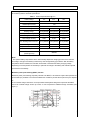
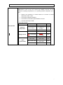
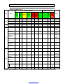
R series solar charger inverter 1000W to 6000W
User’s Manual
Table of Contents:
Figures of Unit..................................……………………….........................................................................3
Line mode specification...........................................................................................................................3
Inverte mode specification...........................................…........................................................................4
AC charge mode specification…………………………….…………………………………………………….5
Solar charge controller mode specification………………………………………………………………….…6
Indicator…………………………………………………………………………………………………….……....7
Remote control……………………………………………………………………………………………..………8
Audible alarm…………………………………………………………………………………………………...….8
Fan operation………………………………………………………………………………………………………9
General specification…………………………………………………………………………………………….10
Appendix..................................…………………………...……..................................................................11
2
Figures of unit:
Model: R series
1000W/2000W/3000W/4000W/5000W6000W
Line mode specifications:
Input voltage waveform
Sinusoidal (utility or generator)
Nominal input voltage
230VAC
Low line disconnect
184VAC±4%
154VAC±4%
Low line re-connect
194VAC±4%
164VAC±4%
High line disconnect
253VAC±4%
High line re-connect
243VAC±4%
Max AC input voltage
270Vrms
Nominal input frequency
Low line frequency re-connect
Low line frequency disconnect
High line frequency re-connect
High line frequency disconnect
Output voltage waveform
Over-load protection
(SMPS load)
Output short circuit protection
50Hz/60Hz (auto detection)
58+0.3Hz for 60Hz;
48+0.3Hz for 50Hz;
57+0.3Hz for 60Hz;
47+0.3Hz for 50Hz;
64+0.3Hz for 60Hz;
54+0.3Hz for 50Hz;
65+0.3Hz for 60Hz;
55+0.3Hz for 50Hz;
As same as input waveform
Circuit breaker
Circuit breaker
Efficiency (line mode)
>95%
Transfer switch rating
30 amp or 40 amp
Transfer time
(AC to DC)
Transfer time
(DC to AC)
8ms (typical)
6ms (typical)
Pass through without battery
Yes
Max bypass overload current
35 amp or 45 amp: alarm
3
Invert mode specifications:
Model: R series
1000W/2000W/3000W/4000W/5000W/6000W
Output voltage waveform
Sine wave
Rated output power (VA)
1000/2000/3000/4000/5000/6000
Rated output power (W)
1000/2000/3000/4000/5000/6000
Power factor
Nominal output voltage (V)
Nominal output frequency (Hz)
Auto tracking main frequency (Hz)
Output voltage regulation
Nominal efficiency
0~1.0
230VAC
50Hz ± 0.3Hz
Yes (following main first connection)
50Hz @48-54Hz
60Hz @58-64Hz
±10% rms
>80%
(110%<load<125%) ±10%: fault (shutdown output) after 15
Over-load protection
(SMPS load)
minutes;
(125%<load<150%) ±10%: fault (shutdown output) after 60s;
Load>150% ±10%: fault (shutdown output) after 20s
Surge rating (10s)
Capable of starting electric motor
Output short circuit protection
Bypass breaker size
Nominal DC input voltage
Min DC start voltage
Low battery alarm
Low DC input shut-down
High DC input alarm & fault
High DC input recovery
3000/6000/9000/12000/15000/18000VA
2HP
Current limit (fault after 1s)
40Amp
12V/24V/48VDC
10/20/40VDC
10.5V/21.0V42.0VDC ± 0.15VDCx1/2/4
10.0V/20.0V40.0VDC
16.0V/32.0V/64.0VDC
15.5V/31.0V/62.0VDC ± 0.15VDCx1/2/4
Load ≦25W
Power saver
(Enabled on “P/S auto” setting of remote control)
4
AC charge mode specifications:
Model: R series
Nominal input voltage
Input voltage range
Nominal output voltage
Nominal charge current
Charge current regulation
Battery initial voltage
Charger short circuit protection
Breaker size
Over charge protection
1000W/2000W/3000W/4000W/5000W/6000W
230VAC
194/164~243VAC
According to the battery type
35Amp (adjustable)
± 5ADC
0 –15.7 VDC (can operate with 0V battery)
Circuit breaker
40A
Bat. V ≥15V/30V/60VDC
beeps 0.5s every 1s & fault after 60s
5
Solar charge controller specification:
The following lists the electrical specifications.
Table 1
Electrical specifications @ 25℃
Rated voltage
12V
24V
Rated charge current
40A
Rated output current
15A
Self consumption
At idle < 10Ma
48V
Bulk charge
14.5V(default) 29.0V(default)
58.0V(default)
Floating charge①
13.5V(default) 27.0V(default)
54.0V(default)
14.0V(default) 28.0V(default)
56.0V(default)
Equalization charge
①
Over charge disconnection
14.8V
29.6V
59.2V
Over charge recovery
13.6V
27.2V
54.4V
①
Over discharge disconnection
Over discharge reconnection
Temperature compensation
Ambient temperature
①
10.8 V(default) 21.6V(default)
43.2V(default)
12.3V
24.6V
49.2V
-13.2mV/℃
-26.4mV/℃
-52.8mV/℃
0-40℃(full load)
Terminal size
(fine/single wire)
40-60 ℃(derating)
#8AWG
Note:
①
The optional battery temperature sensor automatically adjusts the charging process of the controller
according to the type of the battery is selected by user through battery type selector. With the battery
temperature sensor installed, the controller will increase or decrease the battery charging voltage
depending on the temperature of the battery to optimize the charge to the battery and maintain optional
performance of the battery.
Maximum power point tracking (MPPT) function
Maximum power point tracking, frequently referred to as MPPT, is an electronic system that operates the
photovoltaic (PV) modules in a manner that allows the modules to produce all the power they are capable
of.
The PV-seeker charge controller is a microprocessor-based system designed to implement the MPPT.
And it can increase charge current up to 30% or more compared to traditional charge controllers (see
figure 1).
6
Indicator
SHORE POWER
ON
GREEN LED lighting on AC mode
INVERTER ON
GREEN LED lighting on inverter mode
FAST CHARGE
Yellow LED lighting on fast charging mode
FLOAT CHARGE
GREEN LED lighting on float charging mode
OVER TEMP TRIP
RED LED lighting on over temperature
OVER LOAD TRIP
RED LED lighting on over load
POWER SAVER
ON
GREEN LED lighting on power saver mode (power saver load ≦25W)
Remark:Detail indicator setting refers Appendix 1.
7
Remote control
Battery charger
(shore power on)
LED
Inverter
(inverter power on)
Alarm
(check alarms on box)
Switch
GREEN LED lighting on battery charger mode
GREEN LED lighting on inverter mode
RED LED lighting on alarm
Power saver auto
Power on with saver mode (power saver ≦25W)
Unit off
Power totally off
Power saver off
Power on without saver mode
Audible alarm
Battery voltage low
Battery voltage
high
Inverter green LED lighting, and the buzzer beep 0.5s every 5s.
Inverter green LED lighting, and the buzzer beep 0.5s every 1s, and fault after 60s.
110%<load<125%, no audible alarm in 14 minutes, beeps 0.5s every 1s in 15
Invert mode
over-load
th
minute, and fault after 15 minutes.
125%<load<150%, beeps 0.5s every 1s, and fault after 60s.
Load>150%, beeps 0.5s every 1s, and fault after 20s.
Over temperature
Heat sink temp. ≥105ºC, over temp red LED lighting, beeps 0.5s every 1s;
Remark:Detail alarm setting refers Appendix 1.
Protection
Over
temperature
protection
Back-feed
protection
Fault recovery
Heat sink temp. ≥105ºC, fault (shutdown output) after 30 seconds
Yes
By restart the machine
Fan operation
8
Variable speed fan operation is required in invert and charge mode.
This is to be
implemented in such a way as to ensure high reliability and safe unit and
component operating temperatures in an operating ambient temperature up to
50°C.
•
Speed to be controlled in a smooth manner as a function of internal
temperature and/or current.
•
Fan should not start/stop suddenly.
•
Fan should run at minimum speed needed to cool unit.
•
Fan noise level target <60dB.
The fan logic as below:
Condition
Fan operation
Heat sink
temperature
Charge current
Load%
(Invert mode)
Enter condition
Leave condition
Speed
T ≤ 60℃
T > 65℃
OFF
65 ℃≤ T<85 ℃
T ≤ 60℃ or
T ≥ 85℃
50%
T > 85℃
T ≤ 80℃
100%
I ≤ 15%
I ≥ 20%
OFF
20%< I ≤ 50% Max
I≤ 15%or
I ≥ 50%Max
50%
I > 50% Max
I ≤ 40%Max
100%
Load < 30%
Load ≥ 30%
OFF
30% ≤ Load < 50%
Load ≥ 50%
Load ≤ 20% or
Load ≥ 50%
Load ≤ 40%
50%
100%
9
General specifications
Safety
certification
CE(EN62040-1)
EMC classification
EN62040-2, C2
Operating
temperature
0°C to 40°C
range
Storage
temperature
Operation
humidity
-15ºC ~ 60ºC
5% to 95%
Audible noise
60dB max
Cooling
Forced air, variable speed fan
Size
1000/2000/3000 model: 442*218*179 mm3
4000/5000/6000 model: 598*218*179 mm3
10
Appendix:
Indicator and Buzzer setting
Indicator on top cover
LED on remote control
POWE
BATTER
R
Y
SAVER
CHARGE
ON
R
SHORE
INVE
FAST
FLOAT
OVER
OVER
POWE
RTE
CHARG
CHARG
TEMP
LOAD
R ON
R ON
E
E
TRIP
TRIP
CC
√
×
√
×
×
×
×
√
×
×
×
CV
√
×
√, blink
×
×
×
×
√
×
×
×
Float
√
×
×
√
×
×
×
√
×
×
×
Standby
√
×
×
×
×
×
×
×
×
×
×
Invert
Inverter on
×
√
×
×
×
×
×
×
√
×
×
mode
Power saver
×
×
×
×
×
×
√
×
×
×
×
Battery low
×
√
×
×
×
×
×
×
√
√
Battery high
×
√
×
×
×
×
×
×
√
Status
Line
mode
Alar
m
mode
Item
Overload on
invert mode
Over temp on
invert mode
Over temp on
R
m
every 1s
×
√
×
×
×
√
×
×
√
√
“Audible
alarm”
×
√
√
×
×
×
√
×
×
×
√
√
×
√
×
×
√
×
√
×
×
×
×
×
√
×
√
×
×
×
×
×
×
×
×
×
×
×
×
×
×
√
×
×
×
×
×
×
√
Beep 0.5s
√
every 1s
Beep 0.5s
every 1s
×
×
Battery high
×
√
×
×
×
×
×
√
Over temp
×
×
×
×
√
×
×
×
×
Over charge
×
×
√
×
×
×
×
√
×
×
×
×
×
×
×
×
×
×
×
X
short
Beep 0.5s
√
Fan lock
Back feed
Beep 0.5s
every 5s
√
overload
Buzzer
Alar
Over charge
Inverter mode
mode
RTE
Refer to
line mode
Fault
INVE
Beep 0.5s
every 1s
Beep
continuous
Beep
continuous
Beep
continuous
Beep
continuous
Beep
continuous
Beep
continuous
Remark: √ shows the indicator on. × shows the indicator off. √, blink shows the indicator blinking about 0.5s on and 0.5s off.
11