1
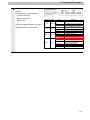
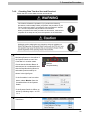
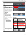
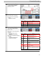
Machine Automation Controller NJ-series
EtherCAT
Connection Guide
OMRON Corporation
3G3MX2-Series Inverter
P521-E1-01
Table of Contents
1.
Related Manuals ........................................................................................ 1
2.
Terms and Definition ................................................................................. 2
3.
Remarks ..................................................................................................... 3
4.
Overview .................................................................................................... 5
5.
Applicable Devices and Support Software.............................................. 5
6.
7.
8.
9.
5.1.
Applicable Devices............................................................................. 5
5.2.
Device Configuration.......................................................................... 6
EtherCAT Settings ..................................................................................... 7
6.1.
EtherCAT Communications Settings .................................................. 7
6.2.
Allocating the Global Variables .......................................................... 7
Connection Procedure .............................................................................. 8
7.1.
Work Flow .......................................................................................... 8
7.2.
Setting Up the Inverter ....................................................................... 9
7.3.
Setting Up the Controller.................................................................. 16
7.4.
Connection Status Check................................................................. 24
Initialization Method ................................................................................ 30
8.1.
Controller ......................................................................................... 30
8.2.
Inverter............................................................................................. 30
Revision History ...................................................................................... 31
1. Related Manuals
1. Related Manuals
The table below lists the manuals related to this document.
To ensure system safety, make sure to always read and heed the information provided in all
Safety Precautions, Precautions for Safe Use, and Precaution for Correct Use of manuals for
each device which is used in the system.
Cat.No.
Model
Manual name
W500
NJ501-[][][][]
NJ-series CPU Unit Hardware User's Manual
W501
NJ501-[][][][]
NJ-series CPU Unit Software User's Manual
W505
NJ501-[][][][]
NJ-series CPU Unit Built-in EtherCAT Port User's Manual
W504
SYSMAC-SE2[][][]
Sysmac Studio Version 1 Operation Manual
I570
3G3MX2-A[][][][]
MX2 User's Manual
I574
3G3AX-MX2-ECT
Inverter MX2/RX Series EtherCAT Communication Unit User's
Manual
1
2. Terms and Definition
2. Terms and Definition
Terms
Explanation and Definition
PDO
This method is used for cyclic data exchange between the master unit
Communications
and the slave units.
(Communications
PDO data (i.e., I/O data that is mapped to PDOs) that is allocated in
using Process Data
advance is refreshed periodically each EtherCAT process data
objects)
communications cycle (i.e., the period of primary periodic task).
The EtherCAT port built into the NJ-series CPU Unit uses process data
communications for commands to refresh I/O data in a fixed control
period, including I/O data for EtherCAT Slave Units, and the position
control data for the Servomotors.
Variables are used to access from the NJ-series CPU Unit in the
following ways.
•With device variables for EtherCAT slave I/O
•With Axis Variables for Servo Drive and encoder input slaves to which
assigned as an axis
SDO
This method is used to read and write the specified slave unit data from
Communications
the master unit when required.
(Communications
The EtherCAT port built into the NJ-series CPU Unit uses SDO
using Service Data
communications for commands to read and write data, such as for
objects)
parameter transfers, at specified times.
You can read/write the following specified slave data with the
EC_CoESDORead (Read CoE SDO) instruction or the
EC_CoESDOWrite (Write CoE SDO) instruction.
•SDO data in slave units (parameters, error information, etc.)
Slave Unit
There are various types of slaves such as Servo Drives that handle
position data and I/O terminals that control the bit signals.
The slave receives output data sent from the master, and transmits input
data to the master.
Node address
An address to identify the unit connected to the EtherCAT network.
ESI file
The ESI files contain information unique to the EtherCAT slaves in XML
(EtherCAT Slave
format.
Information file)
Install an ESI file into the Sysmac Studio, to easily allocate slave process
data and make other settings.
2
3. Remarks
3. Remarks
(1) Understand the specifications of devices which are used in the system. Allow some
margin for ratings and performance. Provide safety measures, such as installing safety
circuit in order to ensure safety and minimize risks of abnormal occurrence.
(2) To ensure system safety, always read and heed the information provided in all Safety
Precautions, Precautions for Safe Use, and Precaution for Correct Use of manuals for
each device which is used in the system.
(3) The users are encouraged to confirm the standards and regulations that the system must
conform to.
(4) It is prohibited to copy, to reproduce, and to distribute a part of or whole part of this
document without the permission of OMRON Corporation.
(5) This document provides the latest information as of March 2013. The information
contained in this document is subject to change for improvement without notice.
About Intellectual Property Right and Trademarks
Microsoft product screen shots reprinted with permission from Microsoft Corporation.
Windows is a registered trademark of Microsoft Corporation in the USA and other countries.
EtherCAT® is registered trademark and patented technology, licensed by Beckhoff Automation
GmbH, Germany.
Company names and product names in this document are the trademarks or registered
trademarks of their respective companies.
3
3. Remarks
The following notation is used in this document.
Precautions for Safe Use
Indicates precautions on what to do and what not to do to ensure using the product safely.
Precautions for Correct Use
Indicates precautions on what to do and what not to do to ensure proper operation and
performance.
Additional Information
Provides useful information.
Additional information to increase understanding or make operation easier.
4
4. Overview
4. Overview
This document describes the procedure for connecting the Inverter (3G3MX2 series) of
OMRON Corporation (hereinafter referred to as OMRON) to the NJ-series Machine
Automation Controller (hereinafter referred to as Controller) on EtherCAT and provides the
procedure for checking their connection.
Refer to Section 7 Connection Procedure to understand the setting method and key points to
connect the devices via EtherCAT.
5. Applicable Devices and Support Software
5.1. Applicable Devices
The following devices can be connected.
Manufacturer
OMRON
OMRON
OMRON
Name
NJ-series CPU Unit
Inverter
EtherCAT Communications Unit
Model
NJ501-[][][][]
3G3MX2-A[][][][]
3G3AX-MX2-ECT
Version
1.1 or later
Additional Information
As applicable devices above, the devices listed in Section 5.2. are actually used in this
document to check the connection. When using devices not listed in Section 5.2, check the
connection by referring to the procedure in this document.
Additional Information
This document describes the procedure to establish the network connection. It does not
provide information about operation, installation nor wiring method of each device.
For details on above products (other than communication connection procedures), refer to
the manuals for the corresponding products or contact your OMRON representative.
5
5. Applicable Devices and Support Software
5.2. Device Configuration
The hardware components to reproduce the connection procedure of this document are as
follows:
Personal computer
(Sysmac Studio installed,
OS:Windows7 )
3G3MX2-A2015 +
3G3AX-MX2-ECT
NJ501-1500
(Built-in EtherCAT port)
Ethernet cable
USB cable
Manufacturer
OMRON
OMRON
OMRON
OMRON
OMRON
OMRON
Name
CPU Unit
(Built-in EtherCAT port)
Power Supply Unit
Sysmac Studio
Personal computer (OS:Windows7)
USB cable
(USB 2.0 type B connector)
Ethernet cable
(with industrial Ethernet connector)
Inverter
EtherCAT Communications Unit
Model
NJ501-1500
Version
NJ1W-PA3001
Ver.1.00
XS5W-T421-[]M[]-K
3G3MX2-A2015
3G3AX-MX2-ECT
V1.1
Precautions for Correct Use
The connection line of EtherCAT communication cannot be shared with other network, such
as Ethernet or EtherNet/IP.
The switching hub for Ethernet cannot be used for EtherCAT.
Please use the cable of category 5 or higher, double-shielded with aluminum tape and
braided shielding and the shielded connector of category 5 or higher.
Additional Information
For information on the specifications of the Ethernet cable and network wring, refer to Section
4 EtherCAT Network Wiring in the NJ-series CPU Unit Built-in EtherCAT Port User's Manual
(Cat. No. W505).
Additional Information
The system configuration in this document uses USB for the connection between the
personal computer and the NJ-series CPU Unit. For information on how to install a USB
driver, refer to A-1 Driver Installation for Direct USB Cable Connection of the Sysmac Studio
Operation Manual (Cat.No. W504).
6
6. EtherCAT Settings
6. EtherCAT Settings
This section provides specifications such as communications parameters and variable names
that are set in this document.
6.1. EtherCAT Communications Settings
The following is the setting of the destination device.
3G3AX-MX2-ECT
(3G3MX2-A[][][][])
Node address
01
6.2. Allocating the Global Variables
The device variables of the destination device are allocated to the Controller's global
variables.
The relationship between the device data and the global variables is shown below.
■Output area (Controller → Destination device)
Destination device data
Global variable name
Data type
Operation command to Inverter
E001_Command
WORD
Output frequency
E001_Frequency_reference
INT
■Input area (Controller ← Destination device)
Destination device data
Global variable name
Data type
Status
E001_Status
WORD
Output frequency monitor
E001_Output_frequency_monitor
INT
■Details of the status allocation (Controller ← Destination device)
Destination device data
Sysmac error status
Error information at
observation level
Error information at minor
fault level
Global variable name
Data type
E001_Sysmac_Error_Status
BYTE
E001_Observation
BOOL
E001_Minor_Fault
BOOL
7
7. Connection Procedure
7. Connection Procedure
This section describes how to connect the Controller via EtherCAT.
This document explains the procedures for setting up the Controller and Inverter from the
factory default setting. For the initialization, refer to Section 8 Initialization Method.
7.1. Work Flow
The following is the procedure for connecting to EtherCAT.
7.2 Setting Up the Inverter
↓
7.2.1 Hardware Settings
↓
7.2.2 Parameter Setting
↓
7.3 Setting Up the Controller
↓
7.3.1 Starting the Sysmac Studio and
Setting the EtherCAT network
configuration
↓
7.3.2 Setting the Global Variables
↓
7.3.3 Transferring the Project Data
↓
7.4 Connection Status Check
↓
7.4.1 Checking the Connection Status
↓
7.4.2 Checking Data that are Sent and
Received
Set up the Inverter.
Check the hardware switches on the Inverter.
Set the Inverter parameters.
Set up the Controller.
Start the Automation Software Sysmac Studio and
set the EtherCAT network configuration.
Set global variables to use for the EtherCAT Slave
Unit.
Transfer the project data from the Sysmac Studio to
the Controller.
Check the connection status of the EtherCAT
network.
Check that the EtherCAT communications are
performed normally.
Check that the correct data are sent and received.
8
7. Connection Procedure
7.2. Setting Up the Inverter
Set up the Inverter.
7.2.1.
Hardware Setting
Check the hardware switches on the Inverter.
Precautions for Correct Use
Make sure that the power supply is OFF when you perform the settings.
9
7. Connection Procedure
1
Mount the EtherCAT
Communications Unit to the
Inverter.
Removing the optional board cover from the Inverter front panel
1. Loosen the mounting screw (x 1) from the optional board cover of the
Inverter front panel.
2. Remove the optional board cover.
*For details on how to mount the
EtherCAT Communications
Unit, 2-4 Mounting and Wiring
for the EtherCAT
Communication Unit in the
Inverter MX2/RX Series
EtherCAT Communications Unit
User's Manual (Cat.No. I574).
Mounting the EtherCAT Communication Unit onto the Inverter
1. Mount the EtherCAT Communication Unit onto the location where the
Inverter optional board cover that you removed was attached. Check
that the connector is firmly connected.
(Notes) When the EtherCAT Communication Unit is mounted, the main
circuit and control circuit terminals of the Inverter are hidden. For
this reason, be sure to wire the main circuit and control circuit
terminals before mounting the EtherCAT Communication Unit.
2. Tighten the mounting screw of the EtherCAT Communication Unit.
Tighten the bottom right screw of the EtherCAT Communication Unit
with the specified torque
(46 N•cm, 4.7 kgf•cm).
Connecting the ground cable of the EtherCAT Communication Unit
1. Ground the FG cable of the EtherCAT Communication Unit.
Cut the ground wire of the unit's FG cable to an appropriate length and
ground it to the closest possible ground location. Also refer to the
Inverter manual.
10
7. Connection Procedure
2
Refer to the right figure and
check the hardware switches on
the EtherCAT Communications
Unit.
3
Set the node address setting
switches to "01".
*Set the node address to "1".
4
Connect the communications
cable to Communications
connector (IN).
In this document, OUT side is not used.
11
7. Connection Procedure
7.2.2.
Parameter Setting
Set the Inverter parameters.
1
Turn ON the power supply to the
Inverter.
*Set the parameters by using
the digital operator on the front
of the Inverter.
Display
Various parameters, frequency/set
value and other data are
displayed (red).
RUN key
Runs the Inverter. Take note that
this key is enabled only when the
RUN command destination is the
Digital Operator.
STOP/RESET This key decelerates the Inverter
to a stop. (Although the
STOP/RESET key is enabled
Key
even when a RUN command is
issued to a destination other than
the Digital Operator (factory
default), it can be disabled by a
Setting (b087).)
If the Inverter is already tripped,
the trip will be reset (return from
the tripping).
Mode key
Parameter is displayed: Move to
the beginning of the next function
group.
Data is displayed: Cancel the
setting and return to the
parameter display.
Individual input mode: Move the
blinking digit to the left.
Regardless of the displayed
screen, pressing and holding this
key (for 1 second or more)
displays the data for Output
Frequency Monitor (d001).
Increment key These keys are used to
increment/decrement a parameter
Decrement key or set data. Pressing and holding
each key increases the
incrementing/decrementing
speed.
Pressing the Increment and
Decrement keys together
activates the "Individual Input
MODE" where each digit can be
edited independently.
Enter key
Parameter is displayed: Move to
the data display.
Data is displayed: Confirm/store
the setting (in the EEPROM) and
return to the parameter display.
Individual input mode: Move the
blinking digit to the right.
12
7. Connection Procedure
2
After turning ON the power
supply, the panel displays as
shown on the right.
Use the procedure on the right
to set the parameter.
[A001] Frequency Reference
Selection 1: 04
[A002] RUN Command
Selection 1: 04
*Set "04" (optional board).
*When the power supply is
turned ON, the data of d001
(Output frequency monitor) is
displayed.
(In the case of factory default
value)
00.00
After turning ON the power
supply, the panel displays as
shown on the left.
Press the
a001
A001 parameter is displayed.
Press the
a002
Increment Key two times.
Change the data to "04".
Press the
a002
Enter Key.
The initial data is displayed.
Press the
a004
Increment Key once.
A002 parameter is displayed.
Press the
02
Enter Key.
The parameter is displayed again.
Press the
a002
Increment Key twice.
Change the data to "04".
Press the
a001
Enter Key.
The initial data is displayed.
Press the
04
Mode Key 3 times.
Enter Key.
The parameter is displayed again.
13
7. Connection Procedure
3
Use the procedure on the right
to set the display selection.
[b037] Display selection: 01
*Set "01" (Individual display of
functions).
*The parameters on the
following step are not displayed
when the factory default setting
(04: Basic display) is used.
a002
The parameter is displayed.
Press the
b001
b001 parameter is displayed.
Press the
b037
Increment Key three times.
Change the data to "01".
Press the
b037
Enter Key.
The initial data is displayed.
Press the
01
Increment Key four times.
b037 parameter is displayed.
Press the
04
Mode Key once.
Enter Key.
The parameter is displayed again.
14
7. Connection Procedure
4
Use the procedure on the right
to set the parameter.
[C102] Reset selection: 03.
*Set "03" (Trip reset only).
b037
The parameter is displayed.
Press the
c001
Mode Key once.
C001 parameter is displayed.
Press the
Increment Key to
move to C102.
c102
C102 parameter is displayed.
Press the
00
Enter Key.
The initial data is displayed.
Press the
Increment Key three
times.
03
Change the data to "03".
Press the
c102
5
Enter Key.
The parameter is displayed again.
Cycle the power supply to the
Inverter.
15
7. Connection Procedure
7.3. Setting Up the Controller
Set up the Controller.
7.3.1. Starting the Sysmac Studio and Setting the EtherCAT Network
Configuration
Start the Automation Software Sysmac Studio and set the EtherCAT network configuration.
Install the software and USB driver beforehand.
1
Start the Sysmac Studio.
Click the New Project Button.
2
The Project Properties Dialog
Box is displayed. Click the
Create Button.
*In this document, New Project
is set as the project name.
3
The New Project Pane is
displayed.
There are Menu Bar and Toolbar
in the upper part of the pane.
Menu Bar
Toolbar
The left pane is called Multiview
Explorer, the right pane is called
Toolbox and the middle pane is
called Edit Pane.
4
Multiview
Explorer
Edit Pane
Toolbox
Select Communications Setup
from the Controller Menu.
16
7. Connection Procedure
Additional Information
For details on the online connections to a Controller, refer to Section 5 Going Online with a
Controller in the Sysmac Studio Version 1.0 Operation Manual (Cat. No. W504).
5
The Communications Setup
Dialog Box is displayed.
Select the Direct connection via
USB Option in the Connection
Type Field.
Click the OK Button.
6
Select Online from the
Controller Menu.
A confirmation dialog is
displayed. Click the Yes Button.
*A displayed dialog depends on
the status of the Controller
used. Select the Yes Button or
other button to proceed with the
processing.
7
8
When an online connection is
established, a yellow bar is
displayed on the top of the Edit
Pane.
Select Mode - PROGRAM
Mode from the Controller Menu.
17
7. Connection Procedure
9
A confirmation dialog is
displayed. Click the Yes Button.
Check that the controller status
on the Toolbox was changed to
the PROGRAM mode.
10
Double-click EtherCAT under
Configurations and Setup in the
Multiview Explorer.
Or, right-click EtherCAT under
Configurations and Setup and
select Edit.
11
The EtherCAT Tab Page is
displayed in the Edit Pane.
12
Right-click the Master Icon and
select Compare and Merge
with Actual Network
Configuration.
A screen is displayed stating
"Get information is being
executed".
18
7. Connection Procedure
13
The Compare and Merge with
Actual Network Configuration
Pane is displayed.
Node address 1 and
3G3AX-MX2-ECT Rev:1.1 are
added to the actual network
configuration of the comparison
result.
Click the Apply actual network
configuration Button.
14
A confirmation dialog box is
displayed. Click the Apply
Button.
Check that node address 1 and
E001 3G3AX-MX2-ECT Rev:1.1
were added to the network
configuration of the Sysmac
Studio. Click the Close Button.
15
Node address 1 and E001
3G3AX-MX2-ECT Rev:1.1 are
added to the EtherCAT Tab
Page in the Edit Pane.
19
7. Connection Procedure
7.3.2. Setting Global Variables
Set global variables to use for the EtherCAT Slave Unit.
1
Select Offline from the
2
Double-click I/O Map under
Controller Menu.
Configurations and Setup on the
Multiview Explorer, or right-click
it and select Edit.
3
The I/O Map Tab Page is
-
displayed on the Edit Pane.
Click a column under Variable to
enter a new variable.
20
7. Connection Procedure
4
Right-click the row for Node1
and 3G3AX-MX2-ECT. Then,
select Create Device Variable.
5
The Variable names and
Variable Types are automatically
set.
Additional Information
The device variable names are created automatically from a combination of the device
names and the I/O port names.
For slave units, the default device names start with an "E" followed by a sequential number
starting from "001"
Additional Information
In the example above, a device variable name is automatically created for each slave.
However, a name can also be automatically created for each I/O port.
Also, you can set any device variables.
21
7. Connection Procedure
7.3.3.
Transferring Project Data
Transfer the project data from the Sysmac Studio to the Controller.
1
Select Online from the
2
When an online connection is
established, a yellow bar is
displayed on the top of the Edit
Pane.
Select Synchronization from
3
4
Controller Menu.
the Controller Menu.
The Synchronization Dialog Box
is displayed.
Check that the data to transfer
(NJ501 in the right figure) is
selected. Then, click the
Transfer to Controller Button.
22
7. Connection Procedure
5
A confirmation dialog is
displayed. Click the Yes Button.
A screen stating "Synchronizing"
is displayed.
6
Check that the synchronized
data is displayed with the color
specified by “Synchronized”,
and that a message is displayed
stating "The synchronization
process successfully finished".
If there is no problem, click the
Close Button.
*If the synchronization fails,
check the wiring and repeat the
procedure described in this
section.
23
7. Connection Procedure
7.4. Connection Status Check
Check the connection status of the EtherCAT network.
7.4.1.
Checking the Connection Status
Check that the EtherCAT communications are performed normally.
1
Select Mode - RUN Mode from the
Controller Menu.
2
A confirmation dialog is displayed.
Click the Yes Button.
Check that the controller status on the
Toolbox was changed to the RUN
mode.
3
Check the LED indicators on the
Controller to confirm if EtherCAT
communication is normally performed.
LED indicators in normal status.
[NET RUN]: Lit green
[NET ERR]: Not lit
[LINK/ACT]: Flashing
24
7. Connection Procedure
4
Check the LED indicators on the
Inverter.
LED indicators in normal status.
[L/A IN]: Flickering
[RUN]: Green ON
[ERR]: OFF
Meaning
Color
Status
OFF
L/A IN
Green
L/A OUT
Green
The LED indicators flash at the same
timing as those of the Controller.
ON
Flickering
OFF
RUN
ERR
ON
Flickering
OFF
Blinking
Green
Single flash
ON
OFF
Blinking
Red
Single flash
Double flash
Flickering
ON
Description
Link not established in physical
layer
Link established in physical layer
In operation after establishing link
Link not established in physical
layer
Link established in physical layer
In operation after establishing link
Init state
Pre-Operational state
Safe-Operational state
Operational state
No error
Communications Setting Error
Synchronization error or
communications data error
Application WDT timeout
Boot error
PDI WDT timeout
25
7. Connection Procedure
7.4.2.
Checking Data That Are Sent and Received
Check that the correct data are sent and received.
The Inverter will start the operation if you perform the following
procedure. Confirm safety before you perform the procedure. If you
cannot confirm the safety, complete the check procedure in Section
7.4.1 and do not perform the procedure in this section.
When you perform the check procedure in this section, make sure to
complete all the steps and to place the operation in the safe state.
1
Check the Monitor Button and Stop
Monitoring Button on the toolbar of
the Sysmac Studio to see if the
Controller is in monitor status.
Check that the Monitor Button is
Monitor
selected and is not selectable and
Stop Monitoring
that the Stop Monitoring Button is
selectable (monitor status) as
shown in the right figure.
*If the Controller is not in monitor
status, select Monitor from the
Controller Menu of the Sysmac
Studio.
*If the Sysmac Studio is offline, go
online by following steps 1 to 4 of
7.3.2.
2
Select Watch Tab Page from the
View Menu.
26
7. Connection Procedure
3
The Watch Tab Page is displayed in
the lower section of the Edit Pane.
4
Click the cell that states Input Name
at the bottom of the Watch Tab
Page.
Now, characters can be entered.
Enter the device variable name.
Enter Operation command to
Inverter: E001_Command.
Type the first character E. A list of
device variables starting with E is
displayed. Scroll the list and select
E001_Command.
Double-click E001_Command.
E001_Command is entered in the
Name Column.
In the same way, enter the following
variables.
Output frequency:
E001_Frequency_reference
Status: E001_Status
Output frequency monitor:
E001_Output_frequency_monitor
5
6
7
Check that the online value of
Status:E001_Status is 0200 (bit 9:
Remote is 1).
*Status bit 9: Remote
0:Local: (Operations from
EtherCAT are disabled)
1:Remote: (Operations from
EtherCAT are enabled)
Status (Status)
Bit
0
1
3
Fault
7
Warning
9
Remote
12
15
-
8
Name
Forward
operation in
progress
Reverse
Operation in
progress
Meaning
0:Stopped/during reverse operation
1:During forward operation
0:Stopped/during forward operation
1:During reverse operation
0:No error or trip occurred for the unit or
Inverter
1:Error or trip occurred for the unit or Inverter
0:No warning occurred for the unit or Inverter
1:Warning occurred for the unit or Inverter
0:Local (Operations from EtherCAT are
disabled)
1:Remote (Operations from EtherCAT are
enabled)
0:During acceleration/deceleration
1:Frequency matching
Frequency
matching
Connection
0:Normal
error between
1:Error (Cannot update data for the Inverter. To
the Optional
restore, turn the power OFF and then ON
Unit and
again.)
Inverter
(Reserved)
The reserved area.
Enter “100” in Output frequency:
E001_Frequency_reference.
27
7. Connection Procedure
9
10
Check that the RUN LED indicator
on the Inverter is unlit and the
7-segment display (Output
frequency) is "0.00".
Enter "1" in the Operation command
to Inverter: E001_Command.
*Command bit 0: Forward/stop
0:Stop
1:Forward command
Command
Bit
11
Name
0
Forward/stop
1
Reverse/stop
7
-
Fault reset
(Reserved)
Meaning
0:Stop
1:Forward command
0:Stop
1:Reverse command
Resets an error or trip for the unit or Inverter.
The reserved area. Set 0.
Check that Status:E001_Status is
“1201” and Output frequency
monitor:E001_Output_frequency_m
onitor is “100”.
*Status bit 0: Forward Operation in
progress
0:Stopped/during reverse
operation
1:During forward operation
*Status bit 12: Frequency matching
0:During
acceleration/deceleration
1:Frequency matching
Status
Bit
0
1
Name
Forward
operation in
progress
Reverse
operation in
progress
3
Fault
7
Warning
9
Remote
12
15
-
Meaning
0:Stopped/during reverse operation
1:During forward operation
0:Stopped/during forward operation
1:During reverse operation
0:No error or trip occurred for the unit or
Inverter
1:Error or trip occurred for the unit or Inverter
0:No warning occurred for the unit or Inverter
1:Warning occurred for the unit or Inverter
0:Local (Operations from EtherCAT are
disabled)
1:Remote (Operations from EtherCAT are
enabled)
0:During acceleration/deceleration
1:Frequency matching
Frequency
matching
Connection
0:Normal
error between
1:Error (Cannot update data for the Inverter. To
the Optional
restore, turn the power OFF and then ON
Unit and
again.)
Inverter
(Reserved)
The reserved area.
28
7. Connection Procedure
12
Check that the RUN LED indicator
on the Inverter is lit and the
7-segment LED indicator (Output
frequency) is “1.00”.
13
Enter “0” in the Output frequency:
E001_Frequency_reference and “0”
in Operation command to Inverter:
E001_Command.
14
Check that the 7-segment LED
display (Output frequency) on the
Inverter shows “0.00” again and
RUN LED indicator is unlit.
29
8. Initialization Method
8. Initialization Method
This document explains the setting procedure from the factory default setting.
If the device settings have been changed from the factory default setting, some settings may
not be applicable as described in this procedure.
8.1. Controller
To initialize the settings of the Controller, select Clear All Memory from the Controller Menu
of the Sysmac Studio.
8.2. Inverter
To initialize the settings of the Inverter, refer to Initialization Setting of 5-14 Other Functions in
the MX2 User's Manual (Cat.No. I570).
30
9. Revision History
9. Revision History
Revision
Date of revision
Revision reason and revision page
code
01
Mar. 26, 2013
First edition
31
2013
P521-E1-01
0911(-)