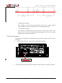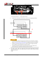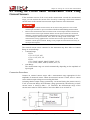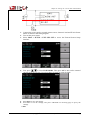
1
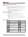
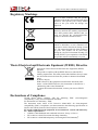
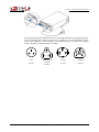
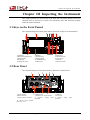
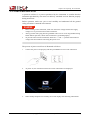
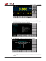
IT9121 Power Meter Installation Instructions Model: IT9121 Notices © Itech Electronics, Co., Ltd. 2014 No part of this manual may be reproduced in any form or by any means (including electronic storage and retrieval or translation into a foreign language) without prior permission and written consent from Itech Electronics, Co., Ltd. as governed by international copyright laws. Manual Part Number IT9121-402147 Revision 1st Edition: September 22, 2014 Itech Electronics, Co., Ltd. Trademarks Pentium is U.S. registered trademarks of Intel Corporation. Microsoft, Visual Studio, Windows and MS Windows are registered trademarks of Microsoft Corporation in the United States and/or other countries and regions. Warranty The materials contained in this document are provided “as is”, and is subject to change, without prior notice, in future editions. Further, to the maximum extent permitted by applicable laws, ITECH disclaims all warrants, either express or implied, with regard to this manual and any information contained herein, including but not limited to the implied warranties of merchantability and fitness for a particular purpose. ITECH shall not be held liable for errors or for incidental or indirect damages in connection with the furnishing, use or application of this document or of any information contained herein. Should ITECH and the user enter into a separate written agreement with warranty terms covering the materials in this document that conflict with these terms, the warranty terms in the separate agreement shall prevail. Technology Licenses The hardware and/or software described herein are furnished under a license and may be used or copied only in accordance with the terms of such license. Safety Notices A CAUTION sign denotes a hazard. It calls attention to an operating procedure or practice that, if not correctly performed or adhered to, could result in damage to the product or loss of important data. Do not proceed beyond a CAUTION sign until the indicated conditions are fully understood and met. A WARNING sign denotes a hazard. It calls attention to an operating procedure or practice that, if not correctly performed or adhered to, could result in personal injury or death. Do not proceed beyond a WARNING sign until the indicated conditions are fully understood and met. Restricted Rights Legend U.S. Government Restricted Rights. Software and technical data rights granted to the federal government include only those rights customarily provided to end user customers. ITECH provides this customary commercial license in software and technical data pursuant to FAR 12.211 (Technical Data) and 12.212 (Computer Software) and, for the Department of Defense, DFARS 252.227-7015 (Technical Data – Commercial Items) and DFARS 227.7202-3 (Rights in Commercial Computer Software or Computer Software Documentation). NOTE A NOTE sign denotes important hint. It calls attention to tips or supplementary information that is essential for users to refer to. IT9121 Power Meter Installation Instructions Quality Certification and Assurance We certify that IT9121 power meter meets all the published specifications. Warranty ITECH warrants that the product will be free from defects in material and workmanship under normal use for a period of one (1) year from the date of delivery (except those described in the Limitation of Warranty below). For warranty service or repair, the product must be returned to a service center designated by ITECH. The product returned to ITECH for warranty service must be shipped PREPAID. And ITECH will pay for return of the product to customer. If the product is returned to ITECH for warranty service from overseas, all the freights, duties and other taxes shall be on the account of customer. Limitation of Warranty This Warranty will be rendered invalid if the product is: Damaged resulting from customer-wired circuits or customer-supplied parts or accessories; Modified or repaired by customer without authorization; Damaged resulting from customer-wired circuits or use in an environment not designated by us; The product model or serial number is altered, deleted, removed or made illegible by customer; Damaged as a result of accidents, including but not limited to lightning, moisture, fire, improper use or negligence. Safety Symbols Direct current ON (power) Alternating current OFF (power) Both direct and alternating current Power-on state Protective earth (ground) terminal Power-off state Earth (ground) terminal Reference terminal Caution Positive terminal Warning (refer to this manual for specific Warning or Caution information) Negative terminal A chassis terminal Copyright © Itech Electronics Co., Ltd. - - i IT9121 Power Meter Installation Instructions Safety Precautions The following safety precautions must be observed during all phases of operation of this instrument. Failure to comply with these precautions or specific warnings elsewhere in this manual will constitute a default under safety standards of design, manufacture and intended use of the instrument. ITECH assumes no liability for the customer’s failure to comply with these precautions. Do not use the instrument if it is damaged. Before operation, check the casing to see whether it cracks or is not applied with sufficient plastics. Do not operate the instrument in the presence of inflammable gasses, vapors or dusts. The maximum operating voltage and current of the instrument are 600V and 20A respectively. Exceeding these limits will lead to burnout of the instrument. Make sure to use the power cord supplied by ITECH. Check all marks on the instrument before connecting the instrument to power supply. Turn off the instrument and the operation system before connecting to the I/O terminal. Do not use the instrument if the detachable cover is removed or loosen. Do not connect the instrument to any cable or terminal block before self-testing. To prevent the possibility of accidental injuries, be sure to use the power adapter supplied by the manufacturer only. Never use the instrument with a life-support system or any other equipment subject to safety requirements. Failure to use the instrument as directed by the manufacturer may render its protective features void. Always clean the casing with a dry cloth. Do not clean the internals. Make sure the vent hole is always unblocked. Environmental Conditions The instrument is designed for indoor use and an area with low condensation. The table below shows the general environmental requirements for the instrument. Environmental Conditions Operating temperature Operating humidity Storage temperature Altitude Pollution degree Requirements 5°C-40°C 20%-80% (non-condensation) -20°C-50 °C ≤2,000m Pollution degree 2 NOTE To make accurate measurements, allow the instrument to warm up for 30 min. Copyright © Itech Electronics Co., Ltd. ii IT9121 Power Meter Installation Instructions Regulatory Markings The CE mark indicates that the product complies with all the relevant European legal directives. The specific year (if any) affixed refers to the year when the design was approved. The instrument complies with the WEEE Directive (2002/96/EC) marking requirement. This affix product label indicates that you must not discard the electrical/electronic product in domestic household waste. This symbol indicates the time period during which no hazardous or toxic substances are expected to leak or deteriorate during normal use. The expected useful life of the product is 10 years. The product can be used safely during the 10-year Environment Friendly Use Period (EFUP). Upon expiration of the EFUP, the product must be immediately recycled. Waste Electrical and Electronic Equiment (WEEE) Directive 2002/96/EC Waste Electrical and Electronic Equipment (WEEE) Directive This product complies with the WEEE Directive (2002/96/EC) marking requirement. This affix product label indicates that you must not discard the electrical/electronic product in domestic household waste. Product Category With reference to the equipment classifications described in the Annex 1 of the WEEE Directive, this instrument is classified as a “Monitoring and Control Instrument”. To return this unwanted instrument, contact your nearest ITECH office. Declarations of Compliance IT9120 Power Meter complies with the following EMC (electromagnetic compatibility), safety and environmental standards: EC Declaration of Conformity - EMC The instrument meets intent of EC Directive 2004/108/EC for electromagnetic compatibility (EMC). Compliance was demonstrated to the following specifications as listed in the Official Journal of the European Communities: EN 61326-1 2006 Electrical equipment for measurement, control and laboratory use - EMC requirements.¹²³ CISPR 11:2003 Radiated and conducted emissions, Group 1, Class A IEC 61000-4-2:2001 Electrostatic discharge immunity. IEC 61000-4-3:2002 Radiofrequency electromagnetic field immunity4. Copyright © Itech Electronics Co., Ltd. iii IT9121 Power Meter Installation Instructions IEC 61000-4-4:2004 Electrical fast transient/burst immunity. IEC 61000-4-5:2001 Power line surge immunity. IEC 61000-4-6:2003 Immunity to conducted disturbances induced by radiofrequency5. IEC 61000-4-11:2004 voltage dips, short interruptions and voltage variations immunity6. EN 61000-3-2:2006 Harmonic emission on AC power line. EN 61000-3-3:1995 Voltage change, fluctuation and flicker 1 The product is intended for use in non-residential/non-domestic environments. Use of the product in residential/domestic environments may cause electromagnetic interference. 2 Connection of the instrument to a test object may produce radiations beyond the specified limit. 3. Use high-performance shielded interface cable to ensure conformity with the EMC standards listed above. 4 Trace bloom not exceeding 4 divisions pk-to-pk may be induced under the test conditions specified in IEC 61000-4-3. 5 Trace bloom not exceeding 1 division pk-to-pk may be induced under the test conditions specified in IEC 61000-4-6. 6 This specification C is applied to 70% voltage drop in 25 cycles and 0% voltage interruption in 250 cycles subject to IEC 61000-4-11. Copyright © Itech Electronics Co., Ltd. iv IT9121 Power Meter Installation Instructions TABLE OF CONTENTS Quality Certification and Assurance .................................................................................................................. 1 Warranty ............................................................................................................................................................ 1 Limitation of Warranty ...................................................................................................................................... 1 Safety Symbols .................................................................................................................................................. 1 Safety Precautions ............................................................................................................................................. 2 Environmental Conditions ................................................................................................................................. 2 Regulatory Markings ......................................................................................................................................... 3 Waste Electrical and Electronic Equiment (WEEE) Directive .......................................................................... 3 Declarations of Compliance............................................................................................................................... 3 Chapter I Introduction .................................................................................................................. 1 1.1 About the Manual ........................................................................................................................................ 1 1.2 Document Information................................................................................................................................. 1 1.3 Product Profile ............................................................................................................................................. 1 1.4 Verifying the Shipment ................................................................................................................................ 2 Chapter II Installing the Instrument ........................................................................................... 3 2.1 Adjusting the Handle ................................................................................................................................... 3 2.2 Removing the Handle .................................................................................................................................. 4 2.3 Rack Mounting ............................................................................................................................................ 5 2.4 Connecting the Power Cord ......................................................................................................................... 6 Chapter III Inspecting the Instrument ........................................................................................ 8 3.1 Keys on the Front Pannel ............................................................................................................................. 8 3.2 Rear Panel .................................................................................................................................................... 8 3.3 Power-on Self-Test ...................................................................................................................................... 9 3.4 Zero Calibration ......................................................................................................................................... 11 3.5 Replacing the Fuse..................................................................................................................................... 11 Chapter IV Wiring the Circuit under Measurement ................................................................ 13 4.1 Precautions when Wiring the Circuit ......................................................................................................... 13 4.2 Wiring the Circuit under Measurement for Direct Input ............................................................................ 14 4.3 Connecting the Circuit under Measurement When Using Current Sensors ............................................... 17 Copyright © Itech Electronics Co., Ltd. v Chapter I Introduction Chapter I Introduction 1.1 About the Manual This manual is your guide to install IT9120 Power Meter and contains the following information: Verifying the Shipment Adjusting the Handle Removing the Handle Rack Mounting Connecting the Power Cord Keys on the Front Panel Rear Panel Power-on Self-Test Zero Calibration Replacing the Fuse Connecting the Circuit under Measurement 1.2 Document Information Installation Instructions are included in the supporting documentations of the instrument which can be accessed via the CD supplied with the instrument or ITECH official website. Manual Title IT9121 Power Meter Installation Instructions (this manual) IT9121 Power Meter User’s Manual IT9121 Programming and Syntax Guide Description Explain how to inspect, install and connect the instrument. Explain how to conduct measurements through front panel operations. Introduce the communication protocol and reference commands applicable to remote operation. 1.3 Product Profile IT9121 Power Meter is a precision power analyzer characterized by powerful and diversified features. It is designed for clearly and correctly measuring the power and energy consumption of various electrical appliances. The maximum input voltage and current of the instrument are 600Vrms and 20Arms; the measuring bandwidth is 100KHZ; and the measurement accuracy is 0.1%. It can meet user’s various measurement demands. By virtue of its DSP+FPGA dual-core processing architecture, IT9121 Power Meter can rapidly and accurately calculate harmonic parameters of signals. In addition, it is equipped with USB, GPIB, RS232 and LAN communication interfaces to accommodate user’s different requirements on communication. Moreover, a USB peripheral component interface is provided for user to store measurement parameters in an external storage medium. Refer to IT9121 User’s Manual for details of general specifications and technical specifications. Copyright © Itech Electronics Co., Ltd. 1 Chapter I Introduction 1.4 Verifying the Shipment Unpack the box and check the contents before operating the instrument. If wrong items have been delivered, if items are missing, or if there is a defect with the appearance of the items, contact the dealer from which you purchased the instrument immediately. The package contents include: Table 1-1 Checklist of Package Contents Item IT9121 Power Meter Qty. Model Remarks x1 IT9121 IT-E171/IT-E172/ IT-E173/IT-E174 x1 Power cord - USB cable x1 CD x1 - Product Recycling Notices Packing List x1 - x1 - Ex-factory Test Report Certificate of Compliance x1 - x1 - User may select an appropriate power cord that matches the specifications of power socket used in the area. Refer to the Section 2.4 Connecting the Power Cord for details of such specifications. It contains IT9121 Power Meter Installation Instructions, User’s Manual, Programming and Syntax Guide and other user documentations. It presents notices on recycling of the instrument. It lists all the package contents. It is the test report of the instrument before delivery. - NOTE Upon verification of the shipment, keep the package and relevant contents thereof in a safe place. When returning the instrument for warranty service or repair, the specified packing requirements shall be met. Refer to IT9121 User’s Manual for detailed requirements on returns. IT9121 AC Power Meter is supplied with the following optional accessories (sold separately): Item IT-E151 (Rack mount kit) Model Remarks To mount the instrument on a special rack, user may select this optional. Refer to the Section 2.3 Rack Mounting for details of installation. Copyright © Itech Electronics Co., Ltd. 2 Chapter II Installing the Instrument Chapter II Installing the Instrument IT9120 Power Meter can be either placed directly on a desktop or mounted on the rack supplied as an optional accessory. 2.1 Adjusting the Handle The instrument is equipped with a handle for user to easily carry and place it. The handle can be adjusted in three manners as shown in the figure below. To adjust the handle, first pull out the handle gently toward the left and right sides of the instrument, and then rotate it slowly to its alignment keys. Horizontal Position Place the instrument horizontally on a desktop. Adjusting the Position 1. Pull out the handle to a rotatable state, as shown below. 2. Rotate the handle to the desired position, as shown below. Copyright © Itech Electronics Co., Ltd. 3 3. Chapter II Installing the Instrument Place the instrument on a desktop, as shown below. ---End 2.2 Removing the Handle To mount the instrument on a rack, first remove the handle from the instrument. The handle can be removed following the procedures below: 1. Rotate the handle to the position as shown in the following figure. NOTE The handle can be easily removed from the alignment hole and key between the handle and the instrument. 2. Pull out the handle toward the left and rights sides of the instrument from the alignment hole. NOTE When mounting or removing the handle, do not squeeze it too hard and mind your hand. ---End Copyright © Itech Electronics Co., Ltd. 4 Chapter II Installing the Instrument 2.3 Rack Mounting IT9121 Power Meter can be mounted on a standard 19” rack. ITECH provides user with IT-E151 rack, an optional mount kit. A standard 19” rack can accommodate two power meters. The detailed mounting procedures are shown as follows: Mounting Procedures 1. Remove the handle by following the procedures described in the Section 2.2 Removing the Handle. 2. Peel off the light grey stickers over the mount positions on both sides of the instrument to expose the rack mount attachment holes. NOTE You may tear one corner of the sticker using a sharp object and then peel it off with hand. 3. Fix the plastic connector onto the rack mount attachment holes at the top right corner of the first power meter with screws, as shown below. 4. 5. Fix the first power meter with screws via the three attachment holes on the rack. Fix the plastic connector onto the rack mount attachment holes on the lower part of the second power meter with screws, as shown below. a. First remove the rack blank panel, as shown in the following figure. Copyright © Itech Electronics Co., Ltd. 5 Chapter II Installing the Instrument b. Then remove the footing at front left corner of the instrument, as shown below: c. Fix another plastic connector onto the rack mount attachment holes at the left bottom corner of the second power meter with screws, as shown below. 6. Fix the three attachment holes of the second power meter on the rack with screws. ---End 2.4 Connecting the Power Cord Connect the power cord after checking that the power switch of the instrument is turned OFF. Only use the power cord supplied as a standard accessory. A summary of connection procedures is given below. Copyright © Itech Electronics Co., Ltd. 6 Chapter II Installing the Instrument Select from the flowing Schedule of Power Cord Specifications an appropriate power cord that matches the voltage for the area in which you use the instrument. If the power cord included in the instrument you purchased does not match the voltage, contact the dealer or manufacturer for change. E E N E E L China IT-E171 L N United States & Canada N L L N Europe England IT-E173 IT-E174 IT-E172 Copyright © Itech Electronics Co., Ltd. 7 Chapter III Inspecting the Instrument Chapter III Inspecting the Instrument This chapter presents you an overview of the front and rear panels and the power-own checkups that are necessary to ensure the instrument starts and functions properly under the initial conditions. 3.1 Keys on the Front Pannel The schematic diagram of front panel and key functions of IT9121 is shown below: 1 USB PCI 4 Waveform Display key 7 Integrator key 10 Enter key 13 Image Save key 2 Display 5 Function key 8 Setting Knob 11 Hold/ESC key 14 Menu key 3 Menu key 6 Harmonics key 9 Arrow keys 12 Set key 15 Power switch 3.2 Rear Panel The schematic diagram of rear panel and key functions is shown below: 1 GP-IB interface 4 RS232 interface 7 External sensor connector 2 Ethernet port 5 External sync signal interface 8 Negative voltage input terminals 3 USB port 6 Power port 9 Positive voltage terminals input 10 Current input terminal protective cover Copyright © Itech Electronics Co., Ltd. 8 Chapter III Inspecting the Instrument 3.3 Power-on Self-Test A power-on self-test is a process performed by the instrument to confirm that the instrument purchased by user meets our delivery standards and can function properly during normal use. Before operation, make sure you’ve read carefully and understand all the general safety precautions contained in the manual. Before turning on the instrument, make sure the mains voltage matches the supply voltage so as to prevent burnout of the instrument. Always put the mains plug into the grounded socket. Never use an ungrounded wiring board. Before operation, check if the instrument is grounded properly. To prevent burnout of the instrument, check the “+” and “-” symbols and maximum voltage and current before connecting the power cord. The process of power-on self-test is illustrated as follows: 1. Connect the power cord properly and then press Power to turn on the instrument. 2. At power-on, the instrument model and version information are displayed. 3. When startup completes successfully, the screen displays the following information: Copyright © Itech Electronics Co., Ltd. 9 Chapter 4. III Inspecting the Instrument Select Menu to access the System Configuration interface. Press SYSTEM to access the SYSTEM INFO interface on which the product model, serial number, computer software version and other information are displayed. 5. Select SELF TEST, and the System Self-Test interface will pop up. Press START to start self-test of the system, including LCD, LED, Display and RAM. Copyright © Itech Electronics Co., Ltd. 10 Chapter III Inspecting the Instrument An “OK” symbol following each test item denotes the test result is acceptable, while a “NG” symbol denotes the test result is subject to user’s self judgment, such as whether LED displays clearly or not. Press KEY TEST to check whether keys function properly. Press all the keys on the front panel; if the icon corresponding to a key shows a black shade, it means the key functions properly. ---End 3.4 Zero Calibration Zero calibration is a feature used to create a state under which input signal is adjusted to zero through the internal circuit; meanwhile, the electrical level is set to zero. NOTE When the measurement range and input filer remain constant for long, the zero level will change with the ambient environment conditions. In this case, zero calibration is recommended. To make accurate measurements, allow the instrument to warm up for at least 30 min before zero calibration .In addition, make sure the ambient temperature is controlled within the specified range. The detailed procedures of zero calibration are shown as follows: 1. Connect the power cord properly and then press Power key to turn on the instrument. 2. Select Menu to access the System Configuration interface. 3. Select CAL ZERO->START to start zero calibration. Wait 1 min for the zero calibration until “Cal Zero is Completed” displays. ---End 3.5 Replacing the Fuse During normal use of the instrument, you need to replace a blown fuse where necessary by following the procedures below: 1. First pull out the power cord, and then take out the fuse block from the power cord jack with a small screwdriver, as shown below: Copyright © Itech Electronics Co., Ltd. 11 Chapter 2. 3. III Inspecting the Instrument Have a visual inspection of the fuse to see whether it is burnt out; if yes, replace it with another fuse of the same specification. T1.25A-250V fuse is used for IT9121 Power Meter. After replacement, mount the fuse block to the original position, as illustrated below: ---End Copyright © Itech Electronics Co., Ltd. 12 Chapter IV Wiring the Circuit under Measurement Chapter IV Wiring the Circuit under Measurement IT9121 Power Meter is an instrument used to measure electric energy factors (including voltage, current and power) of various electrical appliances. This chapter explains how to wire a typical circuit under measurement. User may select to wire the circuit either for direct input or using current sensors, depending on the amplitude of the measured voltage or current. 4.1 Precautions when Wiring the Circuit To prevent electric shock, turn the circuit under measurement off before connection. Always put the mains plug into the grounded socket. Never use an ungrounded wiring board. Before connecting the circuit, make sure the electronic load is grounded properly. Do not wire a current circuit to the voltage input terminal or a voltage circuit to the current input terminal. Strip the insulation covers of the measurement cables so that when they are wired to the input terminals, the conductive parts (bare wires) do not protrude from the terminals. Also, make sure to fasten the input terminal screws securely so that cables do not come loose. When connecting measurement cables to the voltage input terminals, only connect measurement cables that have safety rubber terminals that cover their conductive parts. Also, make sure to fasten the input terminal screws securely so that cables do not come loose. When connecting cables to the external current sensor input terminals, only connect cables that have safety terminals that cover their conductive parts. Also, make sure to fasten the input terminal screws securely so that cables do not come loose. When connecting a measurement cable from an external current sensor to an external current sensor input connector, remove the cables connected to the current input terminals. Also, when the voltage of the circuit under measurement is being applied to the external current sensor input terminals, do not touch the current input terminals. Doing so may impair the measurement accuracy or cause personal injuries. When using an external current sensor, make sure to use a sensor that comes in a case. The conductive parts and case should be insulated, and the sensor should have enough dielectric strength for the voltage of the circuit under measurement. Use measurement cables satisfying the rated conditions and with dielectric strengths and current capacities that are appropriate for the voltage and current being measured. Example: when making measurements on a current of 20A, use copper wires that have a conductive cross-sectional area of 4mm2 or greater. Attaching a measurement cable to the instrument may cause radio interference in which case the user is required to take proper protective measures. Copyright © Itech Electronics Co., Ltd. 13 Chapter IV Wiring the Circuit under Measurement 4.2 Wiring the Circuit under Measurement for Direct Input Under the condition that the measured voltage and current are within the measurement range, when the voltage is 600V or less and the current is 20A or less, you may measure the current and voltage of the circuit for direct input. There are several patterns of terminal wiring positions shown in the following figures for wiring the voltage input and current input terminals. Depending on the terminal wiring positions, the effects of stray capacitance and the effects of the measured voltage and current amplitudes may become large. To make accurate measurements, refer to the factors below when wring the voltage input and current input terminals. Effects of stray capacitance When you are measuring a single-phase device, you can minimize the effects of stray capacitance on measurement accuracy by connecting the instrument’s current input terminal to the side that is closest to the earth potential of the power supply (SOURCE), as shown below: Effects of the measured voltage and current amplitudes When the measured current is relatively large, connect the voltage input terminal to the side that is closest to the load. When the measured current is relatively small, connect the current input terminal to the side that is closest to the load. When the measured current is relatively large: When the measured current is relatively small: Copyright © Itech Electronics Co., Ltd. 14 Chapter IV Wiring the Circuit under Measurement Voltage input terminals The terminals are safety banana jacks (female). Only insert a safety terminal whose conductive parts are not exposed into a voltage input terminal. Current input terminals The terminals are binding posts, and the screws are M6. Either wind a wire around a screw or pass a crimped terminal through the screw axis, and then tighten firmly with the terminal knob. Connection Procedures The procedures of wring the circuit when measuring relatively small current are shown as follows: 1. Remove the protective cover over the current input terminals. Protective Cover 2. The current input and voltage input terminals on the rear panel are shown as follows: Copyright © Itech Electronics Co., Ltd. 15 Chapter IV Wiring the Circuit under Measurement 1: Current input terminals 2: Voltage input terminals Connect the circuit under measurement as shown in the wiring diagram below: 3. 4. Use measurement cables satisfying the rated conditions and with dielectric strengths and current capacities that are appropriate for the voltage and current being measured. Refer to IT9121 Power Meter User’s Manual for detailed specifications of conductor. Example: when making measurements on a current of 20A, use copper wires that have a conductive cross-sectional area of 4mm2 or greater. Attaching a measurement cable to the instrument may cause radio interference in which case the user is required to take proper protective measures. For safety reasons, after you connect the circuit under measurement, attach the protective cover over the current input terminal to prevent contact with the terminal during measurement. ---End Copyright © Itech Electronics Co., Ltd. 16 Chapter IV Wiring the Circuit under Measurement 4.3 Wiring the Circuit under Measurement When Using Current Sensors If the maximum current of the circuit under measurement exceeds the measurement range, you can measure the current of the circuit by connecting a dual-circuit external current sensor to the external current sensor input connector of the instrument. When using an external current sensor, do not remove the protective cover on the current input terminals to prevent contact with the terminal during measurement. Remove the measurement cable connected to the current input terminal. Because the external current sensor input terminal and the current input terminal are connected internally, connecting both terminals simultaneous may result in measurement errors or cause damage to the instrument. Also, when the voltage of the circuit under measurement is being applied to the external current sensor input terminals, do not touch the current input terminals. Doing so may impair the measurement accuracy or cause personal injuries. The external current sensor connected to the instrument may have either a Constant Range or an Auto Range. Constant Range EXT1, CF=3: 2.5V, 5V, 10V CF=6: 1.25V, 2.5V, 5V EXT2, CF=3: 50mV, 100mV, 200mV, 500mV, 1V, 2V CF=6: 25mV, 50mV, 100mV, 250mV, 0.5V, 1V Auto Range The measurement range can switch automatically depending on the amplitude of input signal. Connection Procedures Connect an external current sensor with a measurement range appropriate for the amplitude of measured current. When the measured current is 100A, select a current sensor with an output voltage not exceeding this limit. Assuming that the output voltage generated by 1A current flowing the current sensor is X mV (Conversion Ratio), the maximum voltage generated by 100A flowing a 10mV current sensor is 10mV/A×100A = 1V. Therefore, the measurement range of the current sensor must be EXT2, and the Conversion Ratio is set at 10mV/A. Copyright © Itech Electronics Co., Ltd. 17 Chapter 1. 2. 3. 4. IV Wiring the Circuit under Measurement Connect the power supply, external current sensor, electronic load and IT9121 Power Meter as shown in the wiring diagram. Turn on the power meter. Select Menu > SETUP > EXT SEN SET to access the External Sensor Setup interface. First press to select ExSENSOR2. Then press ON to turn on the external current sensor and set the Conversion Ratio at 10mV/A using the knob. Press Enter to save the settings. Press Esc to exit the settings; and press A-RANGE on the Integ page to query the settings. ---End 5. 6. Copyright © Itech Electronics Co., Ltd. 18 Chapter IV Wiring the Circuit under Measurement Contact Information: Ttech Electronics Co., Ltd. Address: 108 XiShanqiao South Road, Yuhuatai District, Nanjing, Jiangsu, China Tel: 86-25-52415098 Fax: 86-25-52415268 E-mail: [email protected] Copyright © Itech Electronics Co., Ltd. 19