1
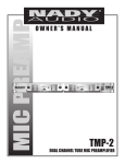
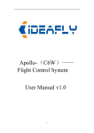
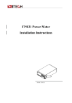
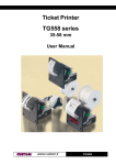
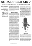
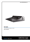
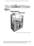
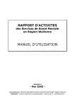
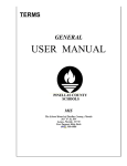
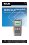
SPL-32R / SPL-32T
UHF Wireless Tour Guide System
User Manual
SPL-32T
SPL-32R
SOOLAI ELECTRONICS CO., LTD
Thank you for choosing SOOLAI!
Please take a few moments to read these instructions carefully, as we want you to
enjoy your new SOOLAI products quickly and to the fullest.
Special features
●Super portable design -Super mini, light weight, metal shell.
●UHF professional frequency, PLL synthesized design, 32 channels available.
●"Digital Pilotone & Noise Lock" dual-squelch Circuitry.
●High performance double-IF circuit design.
●96*64 dot matrix White LCD display.
● LCD display Channel, frequency, volume, battery, RF level, AF level, transmitter
gain, RF power, and lock. Mode.
● Transmitter dynamic display of AF level, AF overload warning, 31-step
microphone gain adjustment design.
●Quick-mute function.
●Receiver digital 16-step volume control.
●Receiver digital 21-step SQ adjusting.
●Panel lock with password.
●Built-in polymer ion polymer battery, safe, light and good to environment.
●Unique clip-worn design.
●Line input,support of inputting backgroud music (CD,MP3) while talking.
●Operating range 600 ft in open ground.
Main Applications
Applications:
Industry Touring
Widely used in touring, visiting museums, exhibitions
Guest reception
Used in reception of visitants in product presentation, advanced exhibition of large
companies
Teaching
Used in meeting and teaching of school and so on
Simultaneous interpretation
International conference simultaneous interpretation
Stage monitoring
Monitoring of performance: especially for acting singer to monitor accompaniment
-2-
CONTENT
.... 04
SPL-32R receiver ……………
……………..………………………………………
………………………………………....
...
…………………………… 05
O perating controls ………………………
………………………...
...……………………………
....………
………
.. 06
A djusting channel/frequency …………
…………..
………..……………………
……………………..
....……
……
.. 06
Adjusting the squelch threshold …………
…………..
……..………………………
………………………..
S etting locking/unlocking …………
…………..……………………………………
…………………………………….. 07
.. 07
E xiting from setting operation ……………
……………..……………………………
……………………………..
....…………………………
…………………………
.. 08
SPL-32T transmitter ………………………
………………………..
…………………………..
....……………………
……………………
O perating controls …………………………
…………………………..
……………………..……
…….. 09
....………………………
………………………
.. 10
A djusting channel/frequency …………………
…………………..
………………………..
....……………
……………
.. 11
Adjusting microphone gain ………………………………
………………………………..
……………..
..
…………………
..
Adjusting transmitting power ………………………
………………………....…………………
………………….. 12
S etting locking/unlocking .………………………………………………
……………………………………………….. 12
....…………
…………
.. 13
Operating belt clip …………………………………………
…………………………………………..
…………..
......
........................................
......... 14
SC-02 two unit charger………………
………………......
..............................................
.................................................
....………
………
SCB-20 twenty unit charging and storing case …………………
…………………..
……….... 15
………………………………………………………………
.16
Application samples
samples………………………………………………………………
……………………………………………………………….16
18
Troubleshooting ……………………………………………………………………
……………………………………………………………………18
....…………
…………
Specifications ………………………………………
………………………………………..
…………..………
……….. 19
………………………
.........
...………………
FCC STATEMENT
STATEMENT...
………………......………………………
……………………….........
....................... 20
……………………………………………………………
Warranty
Warranty……………………………………………………………
……………………………………………………………..….. 21
-3-
SPL-32R receiver
SPL-32R
LCD display
(figure 1)
(1). LCD display
(2). On / Off button (keeping it pressed for 3 seconds will switch the receiver on)
(3). Tie pillar or 1/4 wavelength flexible antenna
(4). 3.5 mm jack socket for earphones
(5). Rocker button (UP)
(6). Rocker button (DOWN)
(7). SET button
(8). Charging contact
(9). Channel display
(10).Frequency display
(11).16-step headphone output volume display
(12). 6-step dynamic RF display
(13). Lock mode icon (lock mode is activated)
(14). 4-step battery status display
(15). 6-step dynamic AF display
(16). Audio overload display, ‘OL’ means transmitter microphone input volume is too
high. It needs to be reduced (adjusting transmitter AF gain until there is no OL
on display)
-4-
Operating controls
1. Via keeping ON/OFF button pressed for 3 seconds, you can switch the receiver on.
2. Via pressing UP or DOWN button, you can add or reduce headphone volume.(The
minimum is 1, and the max is 16.)
3. Via keeping ON/OFF button pressed for 3 seconds, you can switch receiver off.
4. Via keeping“Set” button pressed for 3 seconds, you can enter the operating menu,
as shown in the figure 2. If there is no operating menu, you will see the code
inputting picture, as shown in the figure 3. It means the former user has set the
lock mode. You have to input the code, if you want to enter. Please refer to
(Setting Locking/unlocking )
(figure 2)
(figure 3)
● The battery is flat if you can not switch the receiver on. You have to charge before
switch it again.
● The receiver will power off automatically to protect the lithium-ion battery when
the battery is flat. Please charge the battery.
● While the transmitter off, please check the RF on LCD of receiver. If there is no
RF volume display, it means no frequency interference. You can use this channel,
as shown in the figure 4. If there is RF volume display, it means the frequency is
interfered. Please use another channel, as shown in the figure 5.( Please refer to
adjusting channel/frequency ) If there is AF volume on display, it means the
receiver has received signal from one transmitter which is swtiched on (as shown
in the figure 6).
● Set the volume for the connected headphones to the minimum before putting the
headphones on.
(figure 4)
(figure 5)
-5-
(figure 6)
Adjusting channel/frequency
1. Keeping SET button pressed for 3 seconds, you can enter the operating menu.
2. Via “-”or“+” button, you can select “SET CH” icon, as shown in the figure 7.
Then press “Set” button to enter, as shown in the figure 8.
3. Via“-”or “+” button, you can go to the channel you want and then press “Set”
button. The channel is stored.
(figure 7)
(figure 8)
※ While adjusting the channel, if there is RF display, it means there is interference.
Please change to another channel to ensure perfect performance.
Adjusting the squelch threshold
1. Via keeping “Set”button pressed for 3 seconds, you can enter the operating menu.
2. Via “-”or “+”button, you can select “SET SQ” icon, as shown in the figure 9.
Then press “Set” button to enter, as shown in the figure 10.
3. Via “-”or“+” button, you can adjust the SQ volume, then press “Set” button
to store the setting.
※ While the transmitter being off, if there is RF volume on display of receiver, it
means the receiver is interfered by background noise. Please adjust to another
channel or add the SQ volume. For adding the SQ volume, the transmitting range
will become shorter. The more the SQ is, the shorter the transmitter range becomes.
(The minimum SQ is -10, while the max is +10).
(figure 9)
(figure 10)
-6-
Setting locking / unlocking
1. Keeping “Set” button pressed for 3 seconds, you can enter the operating menu.
※ If there is no operating menu but “CODE?---” displays, it means the former user
has set locking code, as shown in the figure . You have to enter the correct code
via “-”or “+” button. Then press “Set” button to continue. If you enter wrong
codes, there will be “INVALID” on the display. Please enter the correct code. If
the code is lost, you can try enterring the following total 8 codes one by one, until
you can enter successfully. “---”、
“+++”、
“-++”、
“+--”、
“--+”、
“++-”、
“-+-”、
“+-+”.
2. Via “-”or “+” button, you can go to the “LOCK OFF” icon and press “Set”
button to unlock the panel operating, as shown in the figure 11.
3. Via “-”or “+” button, you can go to “LOCK ON” icon and then press “Set”
button, as shown in the figure 12. You will need to enter 3 codes, as shown in the
figure 13.
4. Via “-”or“+” button, you can enter 3 codes. Then press “Set”button to store
the operating. Next time you have to enter the 3 codes before you can enter the
operating menu successfully.
(figure 11)
(figure 12)
(figure 13)
Exiting from setting operation
1. In the operating menu, you can go to “EXIT” icon via “+”or“-” button, as
shown in the figure 14. Then press “ Set ” button to exit from setting
2.
operation.
Under any operation status, the receiver will return to start display if there is
no operation for 5 seconds.
(figure 14)
-7-
SPL-32T transmitter
SPL-32T
LCD display
(figure 15)
(17). LCD display
(18). ON/OFF button, (serve as mute button in operating menu)
(19). 1/4 wavelenth flexible antenna
(20). Microphone/line input (MIC/LINE), 3.5 mm jack socket
(21). Rocker button (UP)
(22). Rocker button (DOWN)
(23). SET button
(24). Charging contact
(25). Channel display
(26). Frequency display
(27). Microphone gain (-10dB----+20dB)
(28). Transmitting RF power output display (NORMAL or HIGH)
(29). Lock mode icon (Lock mode is activated.)
(30). 4-step battery status display
(31). 6-step Audio display
(32). Mute display icon
(33). Audio overload display icon (OL status is activated.) It means the transmitter
microphone input volume is too high . You need to reduce the volume via
adjusting the AF GAIN until the OL icon disappears from the LCD.
-8-
Operating controls
1. Via keeping “ ” button pressed for 3 seconds, you can switch the transmitter on,
as shown in the figure 16.
2. “ ” button serves as mute button in operating menu. You can switch by pressing
the button between mute mode and no mute. It is in mute mode, as shown in the
figure 17
(figure 16)
(figure 17)
3. Via keeping pressing ON/OFF button for 3 seconds, you can switch the transmitter
off.
4. Via keeping pressing “Set” button for 3 seconds, you can enter the operating menu,
as shown in the figure 18. If the “CODE?---” appears, as shown in the figure 19, you
have to enter the correct three codes. Please refer to Setting locking / unlocking.
(figure 18)
(figure 19)
● If you can not switch the receiver on, it means the battery is flat. You have to
charge before open it again.
● The receiver will switch off automatcially when the battery is flat to protect the
lithium-ion battery. Please do not open before you have charged the battery.
● Before using, please insert the microphone to Microphone/line input (MIC/LINE),
3.5 mm jack socket.
● While using, please do not pull out the microphone.
● Please put headmicrophone or lavalier microphone as close as to speaker’s mouth
to get perfect performance.
● In normal speaking volume, if AF display 1-2 steps, it means transmitter
microphone input volume it too low, as shown in the figure 20, which needs to be
adjusted higher via adjusting transmitter AF GAIN. If it is 4-5 steps, it means
-9-
perfect performance. If there is OL icon, you have to adjust AF GAIN lower.
Please refer to Adjusting AF gain.
(figure 20)
(figure 21)
(figure 22)
※ While using, the antenna has to be kept away from direct touching skin to
ensure perfect performance.
Adjusting channel/frequency
1. Via keeping “Set” button pressed for 3 seconds, you can enter operating menu 2
2. Via “-”or“+” button, you can go to “SET CH” icon, as shown in the figure
then press “Set” button to enter, as shown in the figure 24.
3. Via “-”or“+” button, you can go the the channel you want, then press “Set”
button to confirm.
(figure 23)
(figure 24)
● Please do not change channel or frequency at will, unless the using channel is
interfered.
- 10 -
Adjusting transmitter microphone gain
1. Keeping pressing “Set” button for 3 seconds, you can enter the operating menu.
2. Via “-”or“+” button, you can go to “SET GAIN” icon, as shown in the figure
25. And then press “Set” button to confirm, as shown in the figure 26.
3. Via “-”or“+” button, you can adjust the AF GAIN and press “Set” button to
confirm.(The max is +20dB, which means the microphone input volume is enlarged
by 20dBs. While the minimum is -10dB, which means the volume is reduced by
10dBs.)
● The user can adjust the AF GAIN according to AF dynamic volume display. If
OL appears, please reduce AF gain. If AF display 1-2 steps, you need to add AF
gain. Generally, 4-5 steps is the best performance.
(figure 25)
(figure 26)
● While using head microphone, the reference range is 0dB---5dB.
● While using lavalier microphone, the reference range is +13---+18dB.
※ In noisy background, you are suggested to use head microphone to get perfect
performance.
- 11 -
Adjusting transmitting RF power
1. Keeping pressing “Set” button for 3 seconds, you can enter operating menu.
2. Via “-”or “+” button, you can go to “SET PWR” icon, as shown in the figure
27. And press “Set” button to confirm, as shown in the figure 28 or 29.
3. If you select “HIGH” icon, it means you select higher transmiting power---20mW.
4. If you select “NORMAL” icon, it means you select normal transmiting
power---10mW.
(figure 27)
(figure 28)
(figure 29)
Setting locking / unlocking
1. keeping pressing “Set” button for 3 seconds, you will enter operating menu.
● If there is no operating menu, but “CODE?---” icon, it means the former user has
set code. You need to input the code and press “Set” button to confirm. If the
code is wrong, “INVALID” will appear. Please try other codes. If the code is lost,
please try the following total 8 codes one by one, until you can enter.
“---”、“+++”、“-++”、
“+--”、
“--+”、“++-”、“-+-”、
“+-+”.
2. Via“-”
or“+”button, you can go to “LOCK OFF” icon, as shown in the figure
30. Then press “Set” button to confirm unlocking the panel.
3. Via “-”or“+” button, you can go to “LOCK ON” icon, as shown in the figure
31. Then press “Set” button to confirm locking the panel.
4 . Input 3 codes via “-”or “+”button and then press “Set”button. You have set
the code successfully. You will have to input the codes before you enter the
operating menu next time.
(figure 30)
(figure 31)
- 12 -
(figure 32)
Operating belt clip
(figure 33)
(34)Belt clip plastic shell
( 35)Metal spring clip
1.Insert the transmitter or receiver into the belt clip upwards or downwards, as shown
in the figure 34.
2. Then insert microphone or headphone into jacks of machines.
※If the direction is in downwards, the microphone or headphone should be attached
finally to avoid being crashed.
(figure 34)
- 13 -
SC-02double unit charger
(figure 35)
(42)LED for charging compartment(left)
(43)Charging cmpartment(left)
(44)Charging cmpartment(right)
(45)LED for charging compartment(right)
(46)Power input jack, mini USB 5Pin.
(47)Power adapter, 5V/1A
Operation controls
controls:
1. Connect the power adapter to AC power and connect the other side to Power input
jack on the charger, as shown in the figure 35.
2. Put the machines into the charging compartment upwards. You have being
charging the units.
3. You can charge one or two units once. The charging time is approx 2 hours.
● LED flashing means there is no unit in the charging compartment or the unit does
not touch the charging contact appropriately.
● LED lit means being charged.
● LED off means charging finished.
- 14 -
SCB-20 twenty unit charging and storing case
(figure 36)
(48)charging compartment/storing compartment, 20 units
(49)storing compartment, 20 units
(50)compartment for storing headphone, earphone, etc
(51)compartment for storing Power adapter
(52)Power input jack
(53)Power adapter, 5V/3A
(54)Car power adapter connector SA-503 (Option)
Operation controls
controls:
1. Connect the power adapter to AC power and connect the other side to Power input
jack on the charger, as shown in the figure 36.
2. You can connect input jack of SA-503 to cigarette-lighter Plug on car. And connect
the other side to Power input jack of SCB-20.
3. Put the units into the charging compartment upwards to charge.
4. You can charge the units from 1-20 units at the same time once and the charging
time is approx. 4 hours.
5. You can put total 40 units in SCB-20 for storage.
● LED flashing means no units in the charging compartment or the unit does not
touch the charging contact appropriately.
● LED lit means units being charged.
● LED off means units charging finished.
Pay attentions:
①Do not close the case when you charge the units with enforcing antenna.
②Do not store the units in charing compartment which have enforcing antenna.
- 15 -
Main application samples
In trialogue setting, you are proposed to use the units with enforcing antenna to
enlarge transmitting range. In the following samples, TX means transmitter. RX
means receiver. (A), (B), (C)……means different channels/frequencies: channel A,
channel B, channel C……
touring, visiting
A.touring,
One speaker with many listeners.
1. The speaker can transmit his voice via transmitter.
2. Other listenners can hear via attaching receivers.
The number of receivers can be added at will.
The speaker can take one EL-60 extend linker to input background music. It will make
your touring or visiting more interesting.(The speaker can also hear the music.)
- 16 -
Simultaneous Interpretation
B.Simultaneous
1. The speaker takes one transmitter set on non-interfence channel (TX A) and one
microophone.
2. Mother language listeners take receivers set on the same channnel(RX A) as the
transmitter’s so that they can hear what the speaker is saying.
3. Interpreters take receivers(RX A) for hearing the mother language and transmit
their interpreted languages to other language listenners via attaching transmitters
(TX B, TX C ……)
4. Other language listenners can hear the interpreters’ voice via the their receivers
RX B, RX C …… that are set on the same channel as that of cor
responding
interpreters’.
Pay attentions:
While using multiple channels, please select channels without interence between each
other.
If one takes both one receiver for listenning and one transmitter to interprete what he
hears to another language, he needs to make the distance between the receiver and the
transmitter as far as possible to avoid being interfered.
Please try the following solution if there is still interference. Set the channel into
- 17 -
different frequency ranges, such as range A and range B. (You have to contact
SOOLAI to preset the channel frequency for you!!!) (Please refer to Frequency
diagram on page 21.)
Troubleshooting
No voice in receiver output
1. Make sure the transmitter and receiver are both powered.
2. Make sure the transmitter and the receiver are on the same channel frequency.
3. Make sure the microphone and earphone are attached appropriately.
4. Make sure the transmitter is not in Mute mode
5. Make sure the volume control on receiver is not adjusted on the minimum.
Short working distance
1. Make sure the antenna is not broken.
2. Make sure the transmitter is not close to other transmitter powers. In simultaneous
interpretation, make sure the interpreter’s transmitter and receiver are not on the
same channel frequency.
3. Try to set receiver’s SQ to “MIN -10” to check the effect.
4. Try to use another channel.
5. Check line of sight transmitting range.
Voice distortion
1. Make sure that there is no other transmitter using the same channel.
2. While using multiple channels, make sure there is no interference between each
other.
3. Make sure the transmitter’s microphone GAIN is adjusted to the best volume.
4. Try to adjust the receiver’s SQ to “MAX +10” to check the effect.
Too low voice
1. Make sure the transmitter’s microophone GAIN is adjusted at the best volume.
2. Make sure the receiver’s volume is adjusted at the best volume.
3. Replace the earphone to check the effect.
If still operating problems with your transmission installation occur, please contact
your local SOOLAI agent for assistance.
- 18 -
System Specifications
RF Carrier Frequency Range:
UHF 614~870MHz (country dependent)
Oscillation Type:
PLL Synthesized
Frequency Stability:
±0.005% (0~50)℃
Display Screen:
96*64 dot matrix LCD
Tunable Channels:
32
Switching Bandwidth:
20MHz
Tunable Steps:
625KHz
Modulation:
FM ±45KHz deviation (nominal)
Signal-to-Noise ratio:
>80dB typical (A-weighted )
Total Harmonic Distortion:
<0.8% (Ref.±45KHz deviation,1KHz modu)
Audio Frequency Response:
50hz to 15khz (±3dB);earphone dependent
Power Supply:
Lithium ion polymer battery 3.6v/450mAh
Dimension:
69mm * 42mm * 14mm
Unit Weight:
Less than 50g (With battery)
Operating Temperature:
-10℃ to +55℃
Operating Range
600ft (Environment dependent)
Receiver (SPL-32R):
RF sensitivity:
2uV (60dB S/N)
Antenna:
Uses earphone cable
Squelch:
RF noise squelch & digital Pilotone squelch
AF Output:
100mw maximum ,16setps digital volume
Minimum Load Impedance:
16Ω
Operationg Time:
11 hours
Transmitter(SPL-32T):
RF Power Output:
10mW/20mW(country dependent)
Antenna:
1/4 λ flexible antenna or uses microphone cable
Microphone Input:
Unbalanced, 3.5mm connector(Tip)
Line Input:
Unbalanced, 3.5mm connector(Ring)
Gain Adjustment Range:
Programmable in 31 steps , -10dB to +20dB
Operationg Time:
10 hours (RF Power Output= NORMAL)
- 19 -
RF warning statement
The device has been evaluated to meet general RF exposure requirement. The device
can be used in portable exposure condition without restriction.
FCC STATEMENT
1. This device complies with Part 15 of the FCC Rules.
Operation is subject to the following two conditions:
(1) This device may not cause harmful interference.
(2) This device must accept any interference received, including interference
that may cause undesired operation.
2. Changes or modifications not expressly approved by the party responsible for
compliance could void the user's authority to operate the equipment.
NOTE: This equipment has been tested and found to comply with the limits for a
Class B digital device, pursuant to Part 15 of the FCC Rules. These limits are
designed to provide reasonable protection against harmful interference in a
residential installation.
This equipment generates uses and can radiate radio frequency energy and,
if not installed and used in accordance with the instructions, may cause
harmful interference to radio communications. However, there is no
guarantee that interference will not occur in a particular installation.
If this equipment does cause harmful interference to radio or television
reception, which can be determined by turning the equipment off and on,
the user is encouraged to try to correct the interference by one or more of
the following measures:
n Reorient or relocate the receiving antenna.
n Increase the separation between the equipment and receiver.
n Connect the equipment into an outlet on a circuit different from that to
which the receiver is connected.
n Consult the dealer or an experienced radio/TV technician for help.
- 20 -
WARRANTY
SOOLAI values your business and always attempts to provide you the very best of
service.
No limited warranty is provided by SOOLAI unless your SOOLAI Product was
purchased from an authorized distributor or authorized reseller. Distributors may sell
Products to resellers who then sell Products to end users.
SOOLAI offers a 1-year manufacturer warranty on our main machines: transmitter
and receiver. It warrants that the products will be free from defects in materials or
workmanship (as long as the wireless systems are used under normal circumstances
and properly maintained) for a period of 1- year from the original date of purchase.
This warranty does not cover damage from shipping accidents, misuse, abuse,
operation with incorrect AC voltage, operation with faulty associated equipment,
modification, or alteration without prior factory approval, service by an unauthorized
service center, and normal wear and tear. Evidence of alteration, erasing, or forgery
of proof-of-purchase documents will be cause to void the warranty. Any implied
warranties, including warranties of merchantability and fitness for a particular use,
shall be limited in duration to the period of time set forth above.
All service and repair issues for SOOLAI are handled directly by our authorized
distributors in each local country. Please contact them for servicing issues.
- 21 -
SOOLAI ELECTRONICS CO.,LTD
Add: Xishanqiao, Yuhuatai Zone, Nanjing, 210041, China
Tel : 86-25-52803489
Fax: 86-25-84083635
E-mail:[email protected]
http://www.soolai.com
- 22 -