1
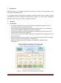
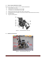
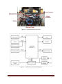
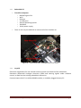
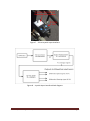
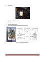
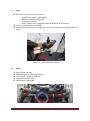
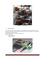
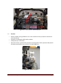
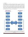
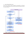
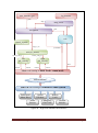
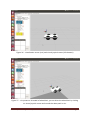
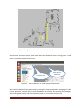
ROS based Multi-sensor Navigation System for a Commercial Wheelchair Technical Report: CES-530 Mohammadreza Asghari Oskoei and Huosheng Hu 31 October 2013 School of Computer Science & Electronic Engineering University of Essex Colchester CO4 3SQ, United Kingdom Email: [email protected]; [email protected] ISSN 1744 - 8050 CES-530, University of Essex, U.K. Page 1 Abstract This report describes an intelligent electric powered wheelchair developed in University of Essex, under the financial support from two EU Research Projects SYSIASS and COALAS. The development of this wheelchair covers a wide range of research activities from multi-modal Human-Machine Interfacing to autonomous navigation. This user manual provides an overview and guidelines to use the wheelchair with autonomous navigation functions. It includes three sections: overview of Hardware parts, overview to Software and a Tutorial that helps the user step-by-step to activate and run the wheelchair without the need of supervision. The research team members include Ling Chen, Ian Dukes, George Francis, Ricky Li, Mohammadreza A. Oskoei, Ericka Rechy-Ramirez, Sen Wang, Lai Wei and Huosheng Hu. Acknowledgements: The authors gratefully acknowledge the support of the EU Interreg SYSIASS project: Autonomous and Intelligent Healthcare System (http://www.sysiass.eu/), and the COALAS project: Cognitive Assisted Living Ambient System (http://www.coalasproject.eu/). The COALAS project has been selected in the context of the INTERREG IVA France (Channel) - England European cross-border co-operation programme, which is cofinanced by the ERDF. The 1st author has been supported by the Mexican National Council of Science and Technology (CONACYT), through the program ''Becas para estudios de posgrado en el extranjero'' (no. 183592). Our thanks also go to Robin Dowling for his technical support during the research. CES-530, University of Essex, U.K. Page 2 Table of Contents 1. Introduction .......................................................................................................................... 4 2. Hardware .............................................................................................................................. 4 2.1 Architecture .............................................................................................................................. 4 2.2 Electric Powered Wheelchair (EPW) ..................................................................................... 5 2.3 Additional Components ........................................................................................................... 5 2.3.1 2.3.2 2.3.3 2.3.4 2.3.5 2.3.6 2.3.7 Embedded PC ................................................................................................................................. 7 Joystick ........................................................................................................................................... 7 Power unit ....................................................................................................................................... 9 Laser ............................................................................................................................................. 10 Sonar ............................................................................................................................................. 10 Micro Controller ........................................................................................................................... 11 Encoder ......................................................................................................................................... 12 3. Software .............................................................................................................................. 13 3.1 Low Level Software (Motion Control) ................................................................................. 14 3.2 High level software (Navigation)........................................................................................... 18 4. Tutorial ............................................................................................................................... 20 4.1 Installation and Configuration.............................................................................................. 21 4.1.1 4.1.2 4.1.3 Install ROS.................................................................................................................................... 21 Setup ROS Workspace.................................................................................................................. 22 Install packages ............................................................................................................................. 24 4.2 Driving Wheelchair Using Remote System .......................................................................... 25 4.2.1 4.2.2 Activate local system (TrimSlice) ................................................................................................ 25 Activate the motors ....................................................................................................................... 26 4.3 Virtual Joystick mode ............................................................................................................ 28 4.4 Autonomous Navigation mode .............................................................................................. 31 4.5 Freewheel mode ...................................................................................................................... 35 5. Conclusion .......................................................................................................................... 35 References ....................................................................................................................................... 36 CES-530, University of Essex, U.K. Page 3 1. Introduction Essex-wheelchair is an intelligent powered wheelchair that adopts new technology to help the elder and disabled people. It is a mobile robot with autonomous navigation, differential motor drive, encoders, joystick and additional sensors including two Hokuyo laser scanners, 12 sonar sensors, Mongoose 9DF IMU, camera with omni-vision, microphone and GPS. Hardware 2. 2.1 • • • • • • Architecture A commercial wheelchair has been fitted with an embedded computer, sensors, control electronics, and wireless networks. Chair is self-contained, powered by the existing on-board batteries, and capable of running some navigation algorithms internally if required. Client/Server Software has been developed to manage data from the sensors and communication with remote computers Client has been interfaced to ROS enabling pre-existing libraries and algorithms to be used on the chair. Sensor Control Electronics is modular, with extensive use being made of small singlechip microcontrollers (allowing easy re-configuration) Serial boot-loaders have been installed in the modules to facilitate future development. Figure 1 - architecture of Essex Wheelchair Hardware CES-530, University of Essex, U.K. Page 4 Electric Powered Wheelchair (EPW) Here are the main parts of ordinary electric powered wheelchair 1) Push handles cross-strut 2) Locking screw for adjusting armrest height 3) Locking screw for adjusting backrest angle 4) Manual wheel lock (only right side visible in the picture) 5) Disengaging lever (not visible in the picture, located on both sides on each motor) 6) Remote control 7) Leg rest unlocking lever 2.2 Figure 2 - Essex wheelchair side view 2.3 Additional Components Figure 3 - Essex wheelchair side view CES-530, University of Essex, U.K. Page 5 Figure 4 - Essex wheelchair rear view Figure 5 - Essex wheelchair block diagram CES-530, University of Essex, U.K. Page 6 2.3.1 Embedded PC • Trim-Slice computer: – NVIDIA Tegra2 CPU – Wi-Fi – Ethernet – 4 x USB ports – Ubuntu Operating System – 32GB SSD – 12Vdc power supply • There is also a 4-port USB Hub to connect all of the modules to. Figure 6 - Essex wheelchair Embedded PC (Trim-Slice) 2.3.2 Joystick Electronic replacement for the manual auxiliary joystick on the back of the wheelchair. Generates differential analogue electronic speed and steering signals under software control, to feed into the existing wheelchair electronics. Communicates with PC via USB-to-RS485 module, so could be plugged into any PC. CES-530, University of Essex, U.K. Page 7 Figure 7 - PC-to-Joystick Input interface Figure 8 - Joystick Input interface block diagram CES-530, University of Essex, U.K. Page 8 2.3.3 Power unit Figure 9 - Power Controller Unit • • • • • Controls 24V power to the PC. Simple Start/Stop buttons. Under-Voltage detection. Executes safe shut-down. Zero current drain from the battery when shut-down. Figure 10 - Power Controller Unit CES-530, University of Essex, U.K. Page 9 2.3.4 Laser Commercial URG-04LX laser scanners: – Angle of scan range is 240 degrees. – Maximum distance range is 4m. – 10 scans per second. – Power Supply: 5Vdc. (supplied from a separate Dc-Dc Converter). They are connected to PC via USB. Shadowing (by the chair-user’s legs) may require two scanners to be fitted (left and right). Figure 11 - URG-04LX Laser Scanner 2.3.5 Sonar Anti-collision sensing. Modified from car reversing sensors. Each module supports 4 sensors. modules have been built. Data output is via RS485. CES-530, University of Essex, U.K. Page 10 Figure 12 - Sonar Sensors 2.3.6 Micro Controller The original microcontroller is removed, and a board based on a PIC18F25K20 is inserted. This micro-controller controls pulse timing, echo delay time measurement, sensor selection and data presentation to the PC. Data transfer to the pc is via the serial driver chip. Cables: 4 x Sensors RS485 Serial Data Power (12Vdc) Figure 13 - Sonar Daughter-board construction CES-530, University of Essex, U.K. Page 11 Figure 14 - Sonar Sensor - Boxed Modules. 2.3.7 • • • • Encoder Rotary encoder spring-loaded to run on the outside of the tyre (due to mechanical size constraints). Encoders are Hengstler RI32 shaft encoders. 1024 pulses per revolution. Data from them is processed by another microcontroller which presents data (which has been converted to mm) to the PC via the RS485 bus. Figure 15 - Wheel Encoders CES-530, University of Essex, U.K. Page 12 3. Software Essex wheelchair has a Client/Server Multi-Layer structure. It consists of two layers: lowlevel and high-level software which are migrated on on-board embedded PC and remote PC, respectively. The low-level software includes server side code, which is responsible to handle the sensors, control the motors and communicate with client side in the high-level. The highlevel software consists of Wheelchair ROS node and ROS packages including navigation. Figure 17 depicts a diagram representing interconnection between two layers of software migrated on on-board (Trimslice PC) and remote (Laptop) systems. This Section describes the software structure in two parts: low-level and high-level. Figure 16 - Essex wheelchair software is migrated on two layers: on-board embedded system and remote PC, which are responsible to motion control and navigation, respectively. CES-530, University of Essex, U.K. Page 13 Low Level Software (Motion Control) Low-level part is running on Trimslice embedded PC and responsible to (i) handle the sensors, (ii) control the motors and (iii) communicate with ROS Client codes. It includes Server code communicating with Client code on the remote system. Flowchart of the Server code is shown in Figure 17. 3.1 Figure 17 - Flowchart of Server code which is running on the on-board system CES-530, University of Essex, U.K. Page 14 Motion control is one of the most important tasks of the Server code. Due to varying conditions (e.g. user’s weight and carpet friction) it adopts PID controllers to maintain a stable velocity for the wheels. The PID controller provides required command based on the desired and actual readings. We designed two PID controllers for speed and steering of the Wheelchair. Figure 18 block diagram of the motion control in the Server code. Figure 18 - Block diagram of PID controllers applied to motion control of the Wheelchair The Server code receives motion commands from high-level part software (ROS Navigation) as the two variables: target_speed and target_steering. They are desired linear and rotational velocity worked out by the high-level part to move the wheelchair. There are two PID controllers responsible for linear and rotational speed of the wheelchair. The PID controllers collect feedback data through the encoders mounted on the left and right wheels. The encoders determine the velocity of left and right wheels. The following equations were used to convert the left and right wheel velocities worked out by the encoders into linear and rotational speeds (width is distance between the left and right wheels). 𝑟𝑖𝑔ℎ𝑡 + 𝑙𝑒𝑓𝑡 𝑠𝑝𝑒𝑒𝑑 = 2 𝑠𝑡𝑒𝑒𝑟𝑖𝑛𝑔 = 𝑟𝑖𝑔ℎ𝑡 − 𝑙𝑒𝑓𝑡 𝑤𝑖𝑑𝑡ℎ Basically, the process in low-level part should be very fast to come up with varying conditions, but in high-level due to high load of computation required for navigation the process is slow. Inherently, the cycle time in Server side is 20Hz while it is 5Hz in Client side. This means we can update sensor data, PID controllers and motor commands in each 50ms and meantime receive commands from and send buffered sensor data to Client side in each 200ms. Optionally, we could speed up communication rate to about 10Hz. This leads to high TCP/IP transmission rate. • • • Client/Server software enables embedded pc to communicate with a remote system. Communication can be via Wi-Fi or Ethernet. Wi-Fi is configured as an Access Point. CES-530, University of Essex, U.K. Page 15 • • • // // // DHCP server has been set up on both Wi-Fi and Ethernet ports. Server (running on embedded PC) Marshals data from the various sensors and modules (which operate asynchronously) and presents it in a unified data structure. Client (running on remote development PC) Requests copies of the data structure when required, returns speed and steering commands to the server. dataFormat.h Include file for the Chair Client/Server. G.Francis, Jan 2013. #define HOST_NAME server #define PORT_ADDRESS #define PORT_ADDRESS_Q requires #define LASER_STEPS readings #define LASER_FRONT reading "192.168.2.2" // Name of the machine 5050 "5050" // Port Address // function call in client 682 // Laser - total number of 341 // struct sonar { int dist1; int dist2; int dist3; int dist4; int updated; }; struct laserFormat { int reading[LASER_STEPS]; int index; int updated; }; struct encoderFormat { long int leftDistance; mm) long int rightDistance; //double x; //double y; //double th; int updated; }; CES-530, University of Essex, U.K. - Center (front) // } (total dist wheel moved, in // } Page 16 struct mongooseRawData { double EULERroll; double EULERpitch; double EULERyaw; double accel_x; double accel_y; double accel_z; double gyro_x; double gyro_y; double gyro_z; double magnetom_x; double magnetom_y; double magnetom_z; double magnetom_heading; short baro_temp; long baro_pres; int accel_x_raw; int accel_y_raw; int accel_z_raw; int gyro_x_raw; int gyro_y_raw; int gyro_z_raw; int magnetom_x_raw; int magnetom_y_raw; int magnetom_z_raw; int updated; }; // ********** Data Packet (from Server to Client) struct dataFormat { struct sonar rearSonar; struct laserFormat rightLaser; struct encoderFormat wheelEncoders; //struct mongooseRawData mongoose; int checksum; }; ********** // ********** Command Packet (from Client to Server) ********** struct commandFormat { int speed; int steering; int checksum; }; Figure 19 - data format communicating between server and client • Additional interface: The chair has now been fitted with an interface to read the front (chair user) manual joystick. This is an analogue-to-digital converter built into the front joystick console, and powered from it. The chair's joystick control panel therefore needs to be engaged (1/0 button) to receive data from it. Data from it appears in the data-structure along with everything else. • This unit has been fitted to allow operation as per the ISEN algorithms, where the user drives with the joystick while the software steers away from obstacles. CES-530, University of Essex, U.K. Page 17 3.2 High level software (Navigation) Essex_wheelchair Package: client code wrapped by ROS which enables the sending and receiving data/commands in ROS message types. Differential_drive Package: The purpose of this package is to provide an interface to the navigation stack. It takes in a twist message from the navigation stack, and provides a lwheel and rwheel messages to be used as motor driver strengths. The package receives wheel encoder messages back from the hardware and generates the tf transform messages required by the ROS navigation stack. This package provides the following nodes: o pid_velocity - A basic PID controller with a velocity target. o twist_to_motors - Translates a twist to two motor velocity targets o virtual_joystick - A small GUI to control the robot. rviz package: A 3d visualization environment for robots using ROS. navigation stack: A 2D navigation stack that takes in information from odometry, sensor streams, and a goal pose and outputs safe velocity commands that are sent to a mobile base. The Navigation Stack is fairly simple on a conceptual level. It takes in information from odometry and sensor streams and outputs velocity commands to send to a mobile base. Use of the Navigation Stack on an arbitrary robot, however, is a bit more complicated. As a pre-requisite for navigation stack use, the robot must be running ROS, have a tf transform tree in place, and publish sensor data using the correct ROS Message types. Also, the Navigation Stack needs to be configured for the shape and dynamics of a robot to perform at a high level. CES-530, University of Essex, U.K. Page 18 user_interface_gui leg_detector goal map map_server map goal navigation rviz virtual_joystick target_vel tf & odom twist_to_motors lwheel_vtarge t rwheel_vtarget left pid_velocity right pid_velocity laser lmotor lwheel rmotor rwheel Client code running on ROS Node: comm-node TCP via wireless SERVER code running at TrimSlice Linux System Differential Motor Drive Optical Encoders Sonar Sensors Hokuyo Laser Mongoose 9DOF IMU Joystick Interface Figure 20 - High Level Software Architecture CES-530, University of Essex, U.K. Page 19 4. Tutorial This tutorial provides step-by-step instructions for how to install and get the wheelchair package running. As the local systems on the wheelchair are pre-installed and maintained just by the admin, the tutorial merely covers installation and configuration of the remote system with ROS and Essex_Wheelchair packages. It also covers driving the wheelchair in manual and software modes. The software mode uses high-level ROS packages on the remote system to drive the wheelchair through either autonomous navigation or virtual joystick. In manual mode, the wheelchair is manipulated by the joystick. The hardware components of wheelchair are presented in Section 2 and the software structure in both low and high levels are described in Section 3. It is assumed you have already got basic knowledge about Ubuntu, ROS and Essex_wheelchair package and are ready to use it. Basically, the wheelchair works in four modes: free-wheel, joystick, virtual joystick and autonomous navigation. The free-wheel mode is the ordinary nature of the wheelchair, in which the wheels are not engaged with the gears, and the user can push it anywhere desired. In this mode, we do not have any control on wheelchair, but we still receive sensory data in the remote system to monitor the trajectory. In joystick mode, the wheels are engaged by the gears, so we could not drive it by pushing but just can manipulate the wheelchair using the joystick. In this mode, the wheelchair avoids obstacles detected by the sonar sensors and also we could monitor the trajectory in remote system using ROS packages using sensory data. In case of a close obstacle, the controller bypasses joystick command moving towards the detected obstacle and stops the wheelchair. Essex_wheelchair can be controlled through the remote system, namely virtual joystick and autonomous navigation. In the both modes, it receives moving commands from remote system rather than the local joystick. Remote system could be either desktop or laptop (or in future a tablet, smartphone) with ROS packages installed. In virtual joystick mode, we could drive wheelchair by sending commands through a remote system meantime track the wheelchair trajectory and visualize sensory data, including laser scans, sonar, odometry, and trajectory using ROS visualization tool. Autonomous navigation is responsible to drive the wheelchair from the current position into destination autonomously. It localizes the robot and destination, plans an optimum path, drives the wheelchair into destination avoiding dynamic obstacles and re-plan a new path if needed. It also supports visualization and mapping tools. Local system, which is an embedded PC configured by the admin, contains sensors and actuators drivers, low-level controlling routines, and bridging tools that communicate with the remote system via TCP (wireless, Ethernet) or USB. The users just need to install required packages on their system (i.e. remote system). They should install Ubuntu (12.04 is suggested), ROS (Groovy is suggested), setup ROS workspace and finally install two overlay packages including differential_drive and essex_wheelchair. CES-530, University of Essex, U.K. Page 20 Section 4.1 provides required guidelines to install and configure the high-level software. Once installations done, the user can follow Section 0 to activate the wheelchair navigation and visualisation functions. Installation and Configuration 4.1 Ubuntu Linux is an open-source operating system that supports full features of ROS. Ubuntu 12.04 is a long-time support version. It is easy to install Ubuntu on-line, from DVD or USB Flash memory. You can keep the current operating system (e.g. Windows) and install Ubuntu turning to dual-boot. It is also possible to have simultaneously running Ubuntu and Windows using virtual machine (e.g. VMware) tools (not recommended). For more details about installation please see https://help.ubuntu.com/community/Installation. 4.1.1 Install ROS ROS (Robot Operating System) is an open-source, meta-operating system that provides libraries and tools to help software developers create robot applications. It provides hardware abstraction, device drivers, libraries, visualizers, message-passing, package management, and more. ROS Groovy is a stable version used to develop essex_wheelchair. You can install ROS either from source (not recommended) or just binary. For more details please see http://www.ros.org/wiki/. Follow the steps below to install ROS Groovy binary (executables) in Ubuntu 12.04: Setup source.list to accept software from packages.ros.org: sudo sh -c 'echo "deb http://packages.ros.org/ros/ubuntu precise main" > /etc/apt/sources.list.d/ros-latest.list' Setup keys: wget http://packages.ros.org/ros.key -O - | sudo apt-key add - Make sure you have re-indexed the ROS.org server: sudo apt-get update Install ROS full desktop: sudo apt-get install ros-groovy-desktop-full CES-530, University of Essex, U.K. Page 21 o By now, ROS core is installed in /opt/ros/groovy and Standard ROS packages are installed in /opt/ros/ groovy/packages Configure environment: echo "source /opt/ros/groovy/setup.bash" >> ~/.bashrc . ~/.bashrc o ROS environment variables are automatically added to bash session every time a new shell (terminal) is launched o .bashrc is a hidden file system in Ubuntu that initiates required environmental variables as a new terminal launched. rosinstall is a frequently used command-line tool in ROS that is distributed separately. It enables you to easily download many source trees for ROS packages with one command. sudo apt-get install python-rosinstall Introduce the system as a master ROS communication centre: echo "export ROS_MASTER_URI=http://localhost:11311" >> ~/.bashrc . ~/.bashrc o Use IP address instead of localhost if ROS master is not the host PC. 4.1.2 Setup ROS Workspace While the core was installed, the standard ROS packages are normally available and you can use them directly. Meantime, developers can create their own packages, install additional packages from source, or even shadow installed packages with experimental versions. It requires setting up an overlay environment, in which they can either create or copy packages and use them along with the primary ones. There are a few ways to manage these "overlay" environments. A user can manage ROS_PACKAGE_PATH and ROS_WORKSPACE environment variables by hand. Alternatively, ROS Workspace provides a systematic method for managing package overlays in a workspace (http://www.ros.org/wiki/fuerte/Installation/Overlays). Here, we introduce how to setup ROS workspace and catkin and manage overlays by setting environment variables. ROS Setup.sh source /opt/ros/groovy/setup.bash CES-530, University of Essex, U.K. Page 22 Catkin workspace Setup mkdir -p ~/catkin_ws/src cd ~/catkin_ws/src catkin_init_workspace cd ~/catkin_ws catkin_make Rosbuild workspace Setup mkdir -p ~/rosbuild_ws/sandbox cd ~/rosbuild_ws/ rosws init ~/rosbuild_ws ~/catkin_ws/devel rosws set -y sandbox rosinstall update echo "source ~/rosbuild_ws/setup.bash" >> ~/.bashrc source ~/.bashrc Verification env | grep ROS look for: ROS_PACKAGE_PATH=/home/<user>/rosbuild_ws/sandbox:/home/<user>/c atkin_ws/src:/opt/ros/groovy/share:/opt/ros/groovy/stacks Workspace Setup by Path Variable o Make a folder in home as a place for the overlays (named here as ros): mkdir ~/ros o Configure overlay environment by redirecting path of packages: echo "export ROS_PACKAGE_PATH=~/ros:$ROS_PACKAGE_PATH" >> ~/.bashrc . ~/.bashrc o ROS core by default is installed in /opt/ros/groovy o Standard ROS packages are installed in /opt/ros/ groovy/packages o Overlay packages are set to be in ~/ros/ CES-530, University of Essex, U.K. Page 23 o New package address is added by export ROS_PACKAGE_PATH= ... o As ordered in ROS_PACKAGE_PATH, overlays are defined in higher priority to be called than the standard packages. Hence, the developers can create package, download source of standard packages or shadow versions into the overlay folder, make modifications and use them without changing the original core. 4.1.3 Install packages To navigate the wheelchair, you need two packages have them installed, including differential_drive and essex_wheelchair. Besides ROS repository, additional packages are often kept in svn (http://subversion.tigris.org/) or github (https://github.com/). It’s recommended (but not necessary) to install repository tools then the packages. First, make sure required tools are installed: sudo apt-get update sudo apt-get install vim tree gitg meld curl openjdk-6-jdk sudo apt-get install zsh terminator sudo apt-get install openssh-server Install 2d_navigation (optional): cd ~/ rosbuild_ws git clone https://github.com/ros-planning/navigation Install differential_drive package: cd ~/ rosbuild_ws rosws set differential_drive --git http://code.google.com/p/differential_drive/ rosws update rosws set differential_drive Install essex_wheelchair package (source): cd ~/ rosbuild_ws rosws set differential_drive --git http://code.google.com/p/essex_wheelchair/ rosws update rosws set essex_wheelchair Check the path of packages by navigating into them: CES-530, University of Essex, U.K. Page 24 roscd differential_drive roscd essex_wheelchair o It should go to the package folder, if not, check the ROS_PATH_PACKAGE Build the main and the depended packages: rosmake –pre-clean essex_wheelchair Driving Wheelchair Using Remote System 4.2 This section includes activating both low and high level tools. It first runs SERVER code on local system (TrimSlice) and then launches Essex_wheelchair package on the remote system. 4.2.1 Activate local system (TrimSlice) To manipulate the wheelchair remotely the local system should be activated. We should activate SERVER code on TrimSlice, which continuously sends sensor data and receives motor commands to/from high-level controlling packages in remote system. The procedure is as following: Make sure the wheels are in geared mode. o Turn the left and right handles shown in Fig xx. Make sure that the Battery of Wheelchair is fully charged. o Check if the Battery charger is connected. o Green light on the charger indicates the battery is full. o Amber light on the charger indicates it is charging now. Turn on TrimSlice by pressing Green Button on the Power Unit (Figure 9). It starts blinking and you should wait it turns to still green light. The Power Unit is placed on leftside of the wheelchair. o blinking green button indicates the process of initiation of TrimSlice. o still green button light shows TrimSlice is ON o pressing Red Button shuts down the Ubuntu and turns off TrimSlice. o Blinking Red Button indicates Ubuntu is shutting down. Connect to TrimSlice-chair wireless connection. o You can see TrimSlice-chair in wireless network list as TrimSlice was ON o Wireless passphrase is jk23fh58, o Wait for stable connection, you lose former wireless connections (i.e. internet) CES-530, University of Essex, U.K. Page 25 Open a new terminal (Ctrl+Alt+T) in your system and initiate a SSH terminal connection to TrimSlice: ssh [email protected] o Passphrase to TrimSlice terminal is ‘a’ o You can make permanent key authorisation using ‘key gen’ o For failure, check if the wireless and TrimSlice are normally running. Activate SERVER code by entering following commands in TrimSlice terminal cd ~/comms ./server o o o o o 4.2.2 In case of error message, check the hardware connections or contact the admin. In normal, you see send/receive data packet counters in the terminal. Keep SERVER code running in its terminal during working with the Wheelchair You can stop SERVER code by pressing Ctrl-C in its terminal. Make sure to stop SERVER code before shutting down the TrimSlice. Activate the motors You have already activated the software on local system and just need to turn on the motor drives and set the wheelchair in Software mode, in which it gets driving commands from the remote system. The following procedures describe how to set the wheelchair in software mode. Activate (or deactivate) the manual wheel lock Figure 21 - manual wheel locks o The manual wheel locks are located on the left and right sides above the wheels. o Pull the lever (1) upwards and backwards till it audibly locks in place. The manual wheel lock is activated. o To release the wheel lock, push the lever (1) completely forward and downward again. CES-530, University of Essex, U.K. Page 26 Engaging (or disengaging) the wheels into the gear o The disengaging levers for the motors are located at the rear on the motor. o Disengaging motors: rotate the engaging lever (1) to the side (position B). o Re-engaging motors: rotate the engaging lever (1) to the rear (position A). Figure 22 - engaging or disengaging the motors Press the I/O button on wheelchair control panel to turn on the motor drives. o A figure LED indicates wheelchair status: Figure 23 - wheelchair control panel and joystick Set the wheelchair in Software mode by turning the key handle to right. o In Software mode, remote system is in charge of control of the motors. Figure 24 - wheelchair control panel and joystick CES-530, University of Essex, U.K. Page 27 4.3 Virtual Joystick mode Having the wheelchair in Software mode and the SERVER code running on local system (TrimSlice), in remote system, we are going to activate ROS packages that can drive the wheelchair using a virtual joystick the screen of remote system. The procedure is as the following: Open a new terminal (Ctrl+Alt+T) in your system and activate ROS core: roscore Open a new terminal (Ctrl+Alt+T) in your system and launch the packages via launch file. roslaunch essex_wheelchair bringup_hardware.launch o launch file works same as batch file in DOS, sets the parameters and activates the executable nodes in sequence. o bringup_hardware.launch (Figure 25) activates hardware including wheelchair node connecting to the local system and controlling nodes. Open a new terminal (Ctrl+Alt+T) in your system and launch the packages via launch file. roslaunch essex_wheelchair bringup_virtualjoystick.launch o bringup_virtualjoystick.launch activates user interface and virtual joystick in the remote system. o Figure 26 depicts the screen of visualization (rviz) and virtual joystick as they were activated. o rvis is a runtime visualization tool, in which you can see the 3D model of wheelchair in the environment, travelled path, laser sensor data, and more. You can change the point of view using mouse actions (Figure 27). o You can drive the wheelchair using virtual joystick by clicking on its screen (Figure 27) and simultaneously see and record the wheelchair path in rviz. CES-530, University of Essex, U.K. Page 28 <launch> <node pkg="essex_wheelchair" type="comms_node" name="comms_node" output="screen"/> <!--node pkg="essex_wheelchair" type="legsDetector_node" name="legsDetector_node" output="screen"/--> <rosparam param="ticks_meter">1000</rosparam> <node pkg="differential_drive" type="pid_velocity.py" name="lpid_velocity"> <remap from="wheel" to="lwheel"/> <remap from="motor_cmd" to="lmotor_cmd"/> <remap from="wheel_vtarget" to="lwheel_vtarget"/> <remap from="wheel_vel" to="lwheel_vel"/> <rosparam param="Kp">40</rosparam> <rosparam param="Ki">10</rosparam> <rosparam param="Kd">0</rosparam> <rosparam param="out_min">-100</rosparam> <rosparam param="out_max">100</rosparam> <rosparam param="rate">10</rosparam> <rosparam param="timeout_ticks">4</rosparam> <rosparam param="rolling_pts">5</rosparam> </node> <node pkg="differential_drive" type="pid_velocity.py" name="rpid_velocity"> <remap from="wheel" to="rwheel"/> <remap from="motor_cmd" to="rmotor_cmd"/> <remap from="wheel_vtarget" to="rwheel_vtarget"/> <remap from="wheel_vel" to="rwheel_vel"/> <rosparam param="Kp">40</rosparam> <rosparam param="Ki">10</rosparam> <rosparam param="Kd">0</rosparam> <rosparam param="out_min">-100</rosparam> <rosparam param="out_max">100</rosparam> <rosparam param="rate">10</rosparam> <rosparam param="timeout_ticks">4</rosparam> <rosparam param="rolling_pts">5</rosparam> </node> <node pkg="differential_drive" type="virtual_joystick.py" name="virtual_joystick" output="screen"> <rosparam param="x_min">-1.5</rosparam> <rosparam param="x_max">+1.5</rosparam> <rosparam param="r_min">-10</rosparam> <rosparam param="r_max">10</rosparam> </node> <node pkg="differential_drive" type="twist_to_motors.py" name="twist_to_motors" output="screen"/> <param name="robot_description" textfile="$(find essex_wheelchair)/launch/essex_wheelchair.urdf" /> <node pkg="rviz" type="rviz" name="rviz" output="screen"/> <node pkg="differential_drive" type="diff_tf.py" name="diff_tf"> <rosparam param="rate">5.0</rosparam> <rosparam param="base_width">0.525</rosparam> </node> <node name="robot_state_publisher" pkg="robot_state_publisher" type="state_publisher" /> </launch> Figure 25 - essex_wheelchair launch file bringup_diff.launch CES-530, University of Essex, U.K. Page 29 Figure 26 - visualization screen (rviz) and virtual joystick screen (left-bottom) Figure 27 - rviz present a 3D model of wheelchair, you can drive the wheelchair by clicking on virtual joystick screen and record the robot path in rviz. CES-530, University of Essex, U.K. Page 30 Autonomous Navigation mode 4.4 Having SERVER code running on local system (TrimSlice), in remote system, we are going to activate ROS packages that can drive the wheelchair with autonomous navigation. Autonomous navigation (AS) is responsible to drive the wheelchair from the current position into destination. Initial pose and destination should be addressed by the user in the global map, and then autonomous navigation attempts to plan a path in the global map and finally it drives the wheelchair by computing the velocity of the motors and sending to the wheelchair given data supplied by both global and local maps. Let's first introduce the concepts we use in autonomous navigation. Global map: In order for the wheelchair to navigate with the Autonomous Navigation, it must have a static map. The map covers the rooms and corridors and shows static and main boundaries such as walls, drawers and etc. It enables the wheelchair to localize itself and receive commands to navigation to a specific location within the map. We currently build the maps using the gmapping package, which uses SLAM to build a map from sensor data published over ROS. Local map: Local map covers near vicinity of the wheelchair and just shows boundaries of obstacles around the wheelchair. It is a dynamic map which is produced by real-time laser scanner readings. Current pose: position and orientation of the wheelchair in global map (X, Y, Theta in a 6-dim pose vector of rviz). Transform frame: the coordination is measured and recorded in various frames (e.g. frame of global, local, base, laser...). Transform frame (tf) maintains the relationship between coordinate frames in a tree structure buffered in time, and lets the user transform points, vectors, etc between any two coordinate frames at any desired point in time. Localization: the pose of wheelchair in the map and real world should match with together. It means that the boundaries produced in local map (shown by blue and red lines) should coincide with boundaries of the global map. At the beginning, the wheelchair is localised manually once then autonomous navigation carries on localizing using odometry data. Destination is a desired pose in global map addressed by the user. Path planer is responsible to find an optimal path (shown by green line on the map) between the current position and destination. Motion control is to consider the motion preferences, wheelchair dimension and specs along with data provided by both local and global maps (cost maps) for computing velocity commands to send to the wheelchair. The procedure to activate autonomous navigation is as the following: Open a new terminal (Ctrl+Alt+T) in your system and activate ROS core: roscore Open a new terminal (Ctrl+Alt+T) in your system and launch the packages via launch file. CES-530, University of Essex, U.K. Page 31 roslaunch essex_wheelchair bringup_hardware.launch o launch file works same as batch file in DOS, sets the parameters and activates the executable nodes in sequence. o bringup_hardware.launch (Figure 25) activates hardware including wheelchair node connecting to the local system and controlling nodes. o Then, differential_drive, visualization and virtual joystick packages should be activated individually, if needed. o Running wheelchair node publishes wheelchair data in ROS topics and receives motor commands via subscribed ROS topics. Open a new terminal (Ctrl+Alt+T) in your system and launch the packages via launch file. roslaunch essex_wheelchair bringup_ui.launch o bringup_ui.launch activates user interface in the remote system. o Figure 26 depicts the screen of visualization (rviz) and virtual joystick as they were activated. o rvis is a runtime visualization tool, in which you can see the 3D model of wheelchair in the environment, travelled path, laser sensor data, and more. You can change the point of view using mouse actions (Figure 27). o You can drive the wheelchair using virtual joystick by clicking on its screen (Figure 27) and simultaneously see and record the wheelchair path in rviz. Open a new terminal (Ctrl+Alt+T) in your system and launch the packages via launch file. roslaunch essex_wheelchair bringup_navigation.launch o bringup_navigation.launch activates a set of nodes including map server (map_server), localization (amcl) and navigation (move_base). o It activates the map_server, sets the map parameters and runs the navigation tools. o Navigation package drives the wheelchair autonomously into the specified goal in the map. o Coordination of the goal can be assigned via visualization tool (e.g. rviz) or a terminal. CES-530, University of Essex, U.K. Page 32 Figure 28 - global map and the travelled path by the wheelchair Autonomous navigation plans a path and drives the wheelchair from starting point to end point. It includes global and local map. Click here for destination Click here for initial pose Figure 29 - how to address the initial pose and destination We should initially build the global map by editing the image produced by mapping tool. We remove particles and keep just the main boundaries of the map. By launching the packages, we see the global (static) and local (dynamic) maps in visualization screen (rviz). CES-530, University of Essex, U.K. Page 33 First, we should localise the wheelchair, it means set the local map on proper point of the global map. Now, the boundaries of the local map (shown by blue and red lines) should match on the global map boundaries. Then by setting the destination on the global map, autonomous navigation plans a path (shown by green line on the map) and then starts to drive the wheelchair to destination. The parameters are needed to be tuned by trying in the field. <launch> <master auto="start"/> <!-- Run the map server --> <node name="map_server" pkg="map_server" type="map_server" args="$(find essex_wheelchair)/common/map.pgm 0.05"/> <!--- Run AMCL --> <include file="$(find amcl)/examples/amcl_diff.launch" /> <node pkg="move_base" type="move_base" respawn="false" name="move_base" output="screen"> <rosparam file="$(find essex_wheelchair)/common/costmap_common_params.yaml" command="load" ns="global_costmap" /> <rosparam file="$(find essex_wheelchair)/common/costmap_common_params.yaml" command="load" ns="local_costmap" /> <rosparam file="$(find essex_wheelchair)/common/local_costmap_params.yaml" command="load" /> <rosparam file="$(find essex_wheelchair)/common/global_costmap_params.yaml" command="load" /> <rosparam file="$(find essex_wheelchair)/common/base_local_planner_params.yaml" command="load" /> </node> </launch> Figure 30 - launch file move_base.launch CES-530, University of Essex, U.K. Page 34 Figure 31 - sample screen of a map supplied by map_server in rviz 4.5 Freewheel mode This is the ordinary level of manipulating a wheelchair. You just should be sure that the wheels are not engaged by the gears. 5. Conclusion Essex wheelchair is an intelligent electric powered wheelchair developed to help the elder and disabled people in their activities. The wheelchair is equipped with wide range of sensors including sonar, laser, compass, IMU, encoder, and camera. It has two DC motors interfaced via the joystick. The wheelchair actuators are based on the differential drive mode. Provided data by the sensors were applied to enhance the interaction between wheelchair and the environment and the user. Essex Wheelchair has multi-layer client/server software structure. Low-level software is migrated on on-board embedded PC and is responsible to handle the sensors, control the motors and communicate with other layers. High-level software is a ROS based package running on the remote PC. It contains wide range of ROS packages to support autonomous navigation, visualization of the wheelchair in the environment, and graphic user interface. ROS package provide simultaneous mapping and localization (SLAM) using the sensor data. CES-530, University of Essex, U.K. Page 35 Essex Wheelchair is developed in University of Essex, under the financial support from two EU Research Projects SYSIASS and COALAS. The development of this wheelchair covers a wide range of research activities from autonomous navigation to multi-modal HumanMachine Interaction. The research team members include Ling Chen, Ian Dukes, George Francis, Ricky Li, Mohammadreza A. Oskoei, Ericka Rechy-Ramirez, Sen Wang, Lai Wei and Huosheng Hu. References [1] [2] [3] [4] ROS Wiki, http://www.ros.org/wiki/ , Differential drive package, http://www.ros.org/wiki/differential_drive , ROS Navigation, http://www.ros.org/wiki/move_base , Pioneer 3AT ROS Setup https://docs.google.com/document/d/1C_GdAAQckIT4H5GnsH3j6OezUbehUphtlnn8XU4XBk/edit#heading=h.763idqd2fisf CES-530, University of Essex, U.K. Page 36


![Delibera n. 0639 del 08 giugno 2015, [file]](http://vs1.manualzilla.com/store/data/006103036_1-78de1975695bfba79ad3b3b760e3ce17-150x150.png)