1
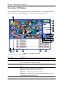
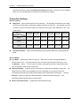
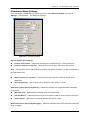
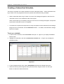
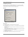
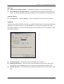
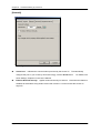
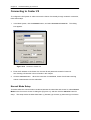
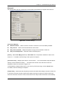
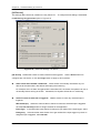
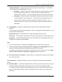
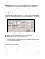
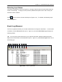
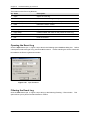
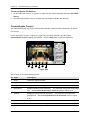
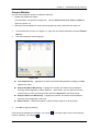
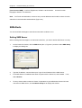
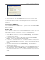
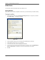
9
CHAPTER
Central Monitoring by
Center V2
With Center V2, central monitoring station (CMS) can be deployed immediately because it brings
multiple GV-Systems together into an integrated interface, allowing the operator to manage several
systems from one point of control. The basic feature of Center V2 is to view live video, and receive
video evidence (in an attachment format) when any alerts are sent to the Center V2. This helps the
remote-end operator easily determine the nature of the alarm.
Installing Center V2
There are two versions of Center V2. The standard version, coming with the system software, can
serve up to 5 subscribers and 80 channels at a time.
The professional version can serve up to 500
subscribers and 800 channels. For professional one, see CMS User’s Manual.
Before installation, make sure your computer meets the following minimum requirements.
The standard version:
OS
Windows 2000, Windows XP, Server 2003
CPU
Pentium 4, 2.0G
Memory
256 MB RAM
Hard Disk
60 GB
VGA
NVIDIA GeForce II 32MB, 1024 x 768 screen resolution
Network
TCP/IP
To install Center V2, follow these steps:
1.
Insert the Surveillance System Software CD to your CMS’s (Central Monitoring Station) computer.
It will run automatically, and a window appears.
2.
Select the Install V8.0.0.0. System item.
3.
Click CenterV2, and follow the on-screen instructions.
Page 232
Chapter 9: Central Monitoring by Center V2
The Center V2 Window
After the installation, start the application from the Windows Start menu. The following monitoring
window will appear. No images will appear until you add and connect to subscribers.
1
2
3
4
5
6
7
9
12
10
11
13
14
15
8
16
17
17
18
19
20
21
22
Figure 9-1 The Center V2 Window
The controls on the Center V2 window:
No
Name
Description
1
Monitoring Window Displays live video.
2
Status Panel
Indicates the date, time, remaining disk space, and the total number of
online channels versus available channels.
3
Find A Subscriber
Type the desired ID in the Current Subscriber field and click this button to
search.
4
Subscriber List
Displays subscribers’ ID names and online status.
Blue Icon: Indicates the subscriber is online.
White Icon: Indicates the subscriber is off-line.
Alarm Icon: Indicates either motion has been detected or the I/O has
been triggered at the subscriber’s site.
Page 233
Chapter 9: Central Monitoring By Center V2
5
Event List
Accesses Event Log and Event List.
6
SMS
Configures the SMS service.
7
I/O Device
Configures and forces output devices at Center V2.
8
Screen Division
In the 1024 x 768 resolution, you can select 6, 15, or 24 screen divisions for
a single monitor; 9, 25, or 36 screen divisions for dual monitors.
In the 1280 x 1024 resolution, you can select 6, 12, or 24 screen divisions
for a single monitor; 9, 20, or 42 screen divisions for dual monitors.
For resolution, see Layout Settings on page 193.
9
Host Info
Displays the connection status of subscribers.
10
Preference
Brings up these options: System Configure, Notification, Password Setup
Settings
and E-mail Setup.
11
Exit
Closes or minimizes the Center V2 window.
12
Accounts
Adds, deletes or modifies subscriber accounts.
13
Refresh Channel
Refreshes the connection status.
14
Next Page
Displays the next page of camera views.
15
Previous Page
Displays the previous page of camera views.
16
Flag
Flags an event for later reference.
17
Clip
Indicates an event coming with an attachment.
Double-click the event to open the attached video file.
18
ID
Indicates a subscriber’s ID.
19
Event Type
Indicates the event type: Alarm, Attachment, Connection, Login/Logout,
Motion, System, and Trigger.
20
Message
Indicates associated information for each event type.
21
Message Time
Indicates when Center V2 receives an event.
22
Start Time
Indicates when an event happens at the subscriber’s site.
A list of Types and Messages will be displayed on Center V2:
Type
Message
Motion
Camera xx detected motion.
Trigger
Module xx triggered.
Connection
Camera xx video lost; Module xx I/O lost; Network abnormal; Fail to login to dispatch
server; Dispatch server is shutdown; Video signal of xx has resumed; Module xx has
returned to normal; Failed to login SMS server; Failed to send short message; SMS
server is shutdown.
Alarm
Disk Full; Restarted Failed; Multicam Closed; There isn’t enough space for recording;
Multicam Surveillance System has been closed; An unexpected error occurred in
Multicam Surveillance System. (Error Code: 1 or 2); There is an intruder;
Object Missing; Unattended Object; Alert Message of POS; Scene Change.
Page 234
Chapter 9: Central Monitoring by Center V2
System
Start/end service; IP change; Record failed; Status change of monitoring camera. On: xx
Off: xx /(By Schedule); Stop/start all cameras monitoring; Start/stop I/O Monitoring. /(By
Schedule); Schedule start; Schedule stop. All monitoring devise are stop too; Start
monitoring all type events; Stop monitoring all type events; Subscriber session is not
established. Wait-time expired; Unexpected logout before subscriber session is
completed.
Attachment
Record file of Camera xx.
Note: Error Code 1 indicates a codec error; Error Code 2 indicates that users can’t write or record
any data due to HD failure or user privilege.
Creating a Subscriber Account
Before starting Center V2, add one subscriber to the center at least. The standard version of Center
V2 only allows 5 subscriber accounts. On the Center V2 window, click the Accounts button (No. 12,
Figure 9-1). The Address Book window appears.
1
2
3
4
5
6
7
Figure 9-2 Subscriber Information
The buttons of the toolbar:
No. Name
Description
1
Add A Group
Adds a group.
2
Add A Subscriber
Adds a subscriber
3
View/Edit Subscriber
Highlight one subscriber and click this button to open Subscriber
Address Book
Address Book for viewing and editing.
4
Delete A Group/Subscriber
Highlight a group or a subscriber and click this button to delete it.
5
Find A Subscriber
Searches a subscriber account.
6
Subscriber Settings
Highlight one subscriber and click this button to configure the
settings of video and alert formats.
7
Subscriber Schedule
Page 235
Sets up subscription schedules.
Chapter 9: Central Monitoring By Center V2
Creating a Subscriber
1. Click the Add A Group button (No. 1, Figure 9-2) to create a group.
2. Click the Add A Subscriber button (No.2, Figure 9-2). The Subscriber Address Book dialog box
appears.
Figure 9-3 Address Book of a subscriber
3.
Enter a login ID and password (required). Those will be the ID and password for the subscriber
to log in to the Center V2.
4.
See Figure 9-12.
Enter the subscriber’s contact information in the rest of fields (optional).
If you wish to send e-mail alerts to this subscriber, enter its e-mail address. For e-mail
settings, refer to E-Mail Alerts, later in this chapter.
If you wish to send SMS alerts to this subscriber, enter its country code and mobile number.
For SMS server settings, refer to SMS Alerts, later in this chapter.
5.
Click the OK button to save the above settings. You will be prompted to this dialog box.
Figure 9-4 Subscriber Settings
6.
The options in the dialog box are discussed below. You may accept the default settings here,
Page 236
Chapter 9: Central Monitoring by Center V2
and edit them later by clicking the Subscriber Settings button (No. 6, Figure 9-2) on the toolbar.
When you click the OK button, the subscriber account then is created.
Subscriber Settings
[Monitor Option]
Image Size: Sets the video size from the subscriber. The following chart tells how the image
size set at the subscriber corresponds to different settings at Center V2. For example, if Center
V2 wants to receive 720 X 240 image, the subscriber must set the video resolution to 720 x 480
or 720 x 240.
Subscriber
Center V2
640 x 480 640 x 240 320 x 240 720 x 480 720 x 240 720 x 576
Normal
320 x 240 320 x 240 320 x 240 360 x 240 360 x 240 360 x 288
Middle
640 x 240 640 x 240 320 x 240 720 x 240 720 x 240 720 x 288
Large
640 x 480 640 x 240 320 x 240 720 x 480 720 x 240 720 x 576
Auto Record Video: Center V2 automatically records events based on the following Record
Mode.
[Record Mode]
Live Mode: Streams live video to Center V2. Make sure you have enough bandwidth to
receive video in live. To set the maximum time of a video clip to be sent to Center V2, click
the Settings… button. The more the set minutes, the bigger the file size; and therefore more
time is required to send the file over Internet.
Attachment Mode: A defined time of event will be recorded before sending to Center V2. The
attachment will be sent out immediately once your subscriber is connected to Center V2.
The Attachment Mode also provides several options associated with the attachment. Click the
Settings… button to bring up the Record Settings – Attachment Mode dialog box. See
Attachment Mode Settings below for further setup.
Both (Live & Attachment): Sends both live and attachment file.
Page 237
Chapter 9: Central Monitoring By Center V2
Attachment Mode Settings
In the Subscriber Settings dialog box (see Figure 9-4), select Attachment Mode, and click the
Settings… button beside. This dialog box appears.
Figure 9-5 Recording Setting
[Record Options (per camera)]
Pre-Rec Total Frames: Determines the total pre-recorded frames in a video attachment.
Pre-Rec Frames/sec Limitation: Determines the frame rate in the pre-recorded period.
Note: Dividing the Pre-Rec Total Frames by Pre-Rec Frames/Sec Limitation, you will get total time of
the video attachment.
Motion Frames/sec Limitation: Determines the frame rate of the video to be sent as an
attachment.
Recording Quality:
Use the slider bar to adjust the video quality in 3 levels.
[Attachment option (Record by Motion)] Defines the duration of the video attachment delivered
upon motion.
Max video Clip: Determines the duration of the video attachment.
Pos-Rec Motion: Determines how many more seconds of video to be sent when motion stops.
Alerts interval: Determines the interval between sent motion events
[Attachment option (Record by I/O trigger)] Defines the duration of the video attachment delivered
upon I/O trigger.
Page 238
Chapter 9: Central Monitoring by Center V2
Creating a Subscriber Schedule
The Center V2 operator can create schedules to monitor subscription status. When subscribers don’t
log in Center V2 on the programmed time, the operator and subscribers will get notified.
•
When a subscriber doesn’t log in Center V2 on time, this message will appear on the Event List:
Subscriber session is not established. Wait-Time expired.
When a subscriber logs out suddenly during a service time, this message will appear: Unexpected
logout before subscriber session is completed.
•
To activate the computer and output alarm to notify the operator while a SMS and E-mail message
being sent out to a subscriber, use the Notification feature. For details, see Notification Settings
later in this chapter.
To set up a schedule
1. On the Center V2 window, click the Accounts button (No. 12, Figure 9-1) to display the Address
Book window.
2. Highlight one subscriber, and click the Subscriber Schedule (No. 7, Figure 9-2) to display the
Schedule window.
Figure 9-6
3. On the Schedule window menu, select Setup Wizard and follow the Wizard instructions.
4. When the following window appears during the instructions, drag the mouse over the Login
timeline to define the Start and End time.
Page 239
Chapter 9: Central Monitoring By Center V2
1
2
3
5
4
Figure 9-7
The controls on the Setup Wizard:
No. Name
Description
1
Include
Displays task time.
2
Exclude
Displays non-task time.
3
Add
Draws task time.
4
Erase
Erase task time.
5
Login
Timeline.
5. Click Next when you finish the schedule. The Setup Wizard dialog boxes pops up again, and
then click Finish to exit.
Page 240
Chapter 9: Central Monitoring by Center V2
Configuring Center V2
On the Center V2 window, click the Preference Settings button (No. 10, Figure 9-1), and select
System Configure to display the following Preference window. This window contains these tabs:
(1) General, (2) Layout, (3) Network, (4) Record and (5) Dispatch Server.
[General]
Figure 9-8 Preference- General Settings
[Monitor Option]
Manual close channel: Closes the triggered camera view manually.
Close the camera view when motion stopped: Closes the triggered camera view automatically
when motion stops.
Post Motion: Specifies the duration of the camera view remaining on the monitoring window
after motion stops.
Camera send by I/O trigger will monitor: Specifies the duration of the camera view remaining
on the monitoring window when an I/O device is triggered.
Image Quality:
Adjusts the video quality. Moving the slide bar to the right side for the better
quality and the bigger image size.
Enable Direcdraw: Enables an enhanced image performance for live video.
Page 241
Chapter 9: Central Monitoring By Center V2
[Start-up]
Auto Run when Windows Starts: Automatically runs Center V2 when Windows starts.
Login SMS Server when Start Service: Automatically logs in SMS Server when Center V2
starts. You will be prompted to enter the IP address, Port, ID and Password of the SMS server.
[Channel Caption]
Font and Color: Click the Settings…. button to change the font and color of the captions.
[Layout]
This function transfers the Event List window to a separate computer while the monitoring windows are
displayed in the current computer. For the application, your VGA card must support Twin View
(discussed in Chapter 11), and your Windows desktop must be properly set up for the display across
two computer monitors.
Figure 9-9 Preference-Layout
Screen Resolution: Detects the current screen resolution on your PC.
Main Panel Resolution: Sets the Center V2 panel resolution to 1024 x768 or 1280 x1024.
This function is only available when your PC screen resolution is higher than 1280 x 1024.
Floating Event List: Moves the Event List window to a separate monitor at the bottom or right
side.
Page 242
Chapter 9: Central Monitoring by Center V2
[Network]
Figure 9-10 Preference- Network Settings
Center Port: Indicates the communication port used by the Center V2. To automatically
configure the port on your router by UPnP technology, click the Arrow button.
For details, see
UPnP Settings, Chapter 6 in the User’s Manual.
Enhance Network Security:
Applies enhanced security for Internet. Note when the feature is
enabled, all subscribers using earlier version than version 7.0 cannot access the Center V2
anymore.
Page 243
Chapter 9: Central Monitoring By Center V2
[Record]
The feature allows you to assign a path to store video files.
Click the Add New Path button
to assign a path; click the [X] button to delete a path.
If the Recycle item is checked, the system will delete old files when storage space falls short of 800MB;
if not checked, Center V2 will stop recording when storage space falls short of 800MB.
Figure 9-11 Preference-Record
Note: Every time when the Recycle function is activated, the files of 400MB will be deleted.
Page 244
Chapter 9: Central Monitoring by Center V2
Connecting to Center V2
To configure the GV-System in order to access the Center V2 remotely through a network connection,
follow these steps:
1.
In the Main System, click the Network button, and select Connect to Center V2. This dialog
box appears.
Figure 9-12 Connect to Center V2
2.
Enter the IP address of the Center V2, the user ID and password created in Center V2.
See Creating a Subscriber’s Account earlier in this chapter.
3.
Click the Connect button. When the connection is established, Center V2 will start receiving
videos or attachments from the subscriber.
Normal Mode Setup
To further define the communication conditions between the subscriber and Center V2, select Normal
Mode on the Connect to Center V2 dialog box (Figure 9-12), and then click the Advance button for
setup. The setup window includes these tabs: (1) General, (2) Camera, (3) Other and (4) I/O Device.
Page 245
Chapter 9: Central Monitoring By Center V2
[General]
The settings define the retry modes and communication ports between GV-System and Center V2.
Figure 9-13 Advance Settings
[Connection Broken]
Maximum Retries:
Sets the number of retries if connection is not immediately available.
Retry Interval: Sets the time interval between each retries.
Retry until connected: Keeps GV-System on trying until connected to Center V2.
Retry in the background:
Hides the retries in the background.
[Codec] Selects Geo Mpeg 4 (default) or Geo H264 as the compression method for video sent to
Center V2. For details, see Recording Codec Options in Chapter 1
[Connective Port] Displays ports used for communication. It is recommended to keep the default
settings, unless otherwise necessary.
The Center Port number must match the Center Port
assigned in Center V2, as shown in Figure 9-10.
To automatically configure these ports on your router by UPnP technology, click the Arrow button.
For details, see UPnP Settings in Chapter 5.
[Temp Folder] Attachments are temporarily stored in this folder while waiting to be sent to Center V2.
In case the connection is broken, attachments meant to be sent to Center V2 could be found here.
Once the connection is back to normal, events saved in the Temp Folder will be sent out immediately.
Page 246
Chapter 9: Central Monitoring by Center V2
[Camera]
The settings define which camera condition to notify Center V2. To configure the event type, first
disable the Monitoring all type events option in Figure 9-12.
Figure 9-14 Advanced Settings- Camera
Send to Center V2 when Motion is Detected:
Sends the video to Center V2 when motion is
detected. Click the Set Camera(s) button to assign cameras for the application.
Event Type: If the subscriber wants Center V2 always to get notified of motion detection, select
Emergency. If the subscriber wants Center V2 to get notified of motion detection only when an
assigned input is triggered, select Normal.
Allow Center V2 to View Live Camera: Gives Center V2 the privilege to view your cameras at
any time. Click the Set Camera(s) button to assign cameras for the application.
Allow Center V2 to Control PTZ Camera:
Gives Center V2 the privilege to control your PTZ
camera. Remember to properly set up camera mapping first. See Mapping PTZ Cameras in
Chapter 1.
Notify Center V2 when the following events come up: Notifies Center V2 when any of these
alert events occur: Intruder, Missing Object, Unattended Object and Scene Change.
Event Type: If the subscriber wants Center V2 always to get notified of these alert events,
select Emergency. If the subscriber wants Center V2 to get notified of these alert events only
when an assigned input is triggered, select Normal.
Note: To set an input trigger for the notification of Normal events, see Security Service, [I/O Device]
later in this chapter.
Page 247
Chapter 9: Central Monitoring By Center V2
[Other]
Define other communication conditions between GV-System and Center V2.
Figure 9-15 Advanced Settings- Other
[Audio] Appling any of these options here may generate privacy issues. Think before you make
any selection.
Allow Audio-Out to CenterV2: Allows Center V2 to listen to the audio from GV-System.
Accept Audio-In from CenterV2:
Allows CenterV2 to use the talkback feature when
emergency occurs.
[Other]
Allow Center V2 to Get System Information:
Allows Center V2 to get system information on
your GV-System.
Send Alert Message of POS’s Loss Prevention to Center V2: Notifies Center V2 about the
events of POS Loss Prevention.
Time synchronization with Center V2: Enables the time increment/decrement of minutes and
seconds at the subscriber site to match the time at the Center V2.
Page 248
Chapter 9: Central Monitoring by Center V2
[I/O Device]
The settings define which I/O condition to notify Center V2. To configure these settings, first disable
the Monitoring all type events option in Figure 9-12.
Figure 9-16 Advanced Settings- I/O Device
[I/O Device] Notifies the Center V2 when I/O devices are triggered. Use the Arrow buttons to
configure each I/O device, or click the Finger button to apply to all I/O devices.
Allow Center V2 to Enable / Disable I/O:
Allows Center V2 manually arm/disarm any I/O
devices at the subscriber’s site without interrupting the monitoring.
For example, when an alarm is triggered at the subscriber site, the Center V2 operator can turn it
off remotely before arriving at the site.
Meanwhile, GV-System still remains on monitoring.
Send to Center V2 when I/O is Triggered: Notifies Center V2 when any selected input is
triggered.
With Camera(s): Sends the camera video to Center V2 when the selected input is triggered.
Click the Set Camera(s) button to assign cameras for the application.
Event Type: If the subscriber wants Center V2 always to get notified of the input trigger, select
Emergency. If the subscriber wants Center V2 to get notified of the input trigger only when an
assigned input is triggered, select Normal.
Page 249
Chapter 9: Central Monitoring By Center V2
Right Arrow button: Sets the delay time to notify Center V2 of input trigger. This feature is
only available when the Normal type is chosen.
Exit Delay:
While the system is activated, this feature provides an interval of time for
the subscriber to exit the premises. During this time, the specified input (e.g. a
exit/entry door) is inactive. Once the exit delay expires, the input will be fully armed.
Entry Delay:
While the system is activated, this feature provides an interval of time
for the subscriber to entry the premises. During this time, the specified input (e.g. a
exit/entry door) is inactive so that the subscriber can disarm the system. If the
subscriber fails to do, once the entry delay expires, Center V2 will get notified of the
input trigger.
Output Module: Enables the assigned output module when the selected input module is
triggered.
For this example, when the I/O Device (Module 1, Input 4) is triggered, the Output (Module 1, Pin 3)
will be activated simultaneously.
Right Arrow button: Sets the delay time to trigger the assigned output module.
Event Type: If the subscriber wants Center V2 always to get notified of the output trigger, select
Emergency. If the subscriber wants Center V2 to get notified of the output trigger only when an
assigned input is triggered, select Normal.
Note:
1. To set an input trigger for the notification of Normal events, see [Security Service] below.
2. The delay settings in Send to Center V2 when I/O is triggered and Output Module allow you to
enter your premises and disable input/output module before it is activated.
To disable prior I/O settings, the subscriber may exit the connection to Center V2 or use the Stop
monitor normal event when selected pin is Triggered feature in Figure 9-16.
Allow Center V2 to Force Output: Allows Center V2 to manually force output devices installed
at the subscriber’s site.
[Security Service] Supports two types of access control systems: Momentary and Maintained
Mode.
Momentary Mode: Pushbutton switches that are normally open and stay closed only as long as
the button is pressed. Momentary switches allow turn-on or turn-off from multiple locations.
For example, certain premises have a designated entry/exit door. When the staff enters the entry
door, the system starts monitoring. When the staff leaves from the exit door, the system stops
monitoring.
Page 250
Chapter 9: Central Monitoring by Center V2
Maintained Mode: Push-on/push off button switches that stay open until thrown, and then stay
closed until thrown again. Maintained switches are convenient for only one switch location.
For example, in the business hour when the door is opened, the system stops monitoring; in the
non-business hour when the door is closed, the system starts monitoring.
Panic Button Setup
You may set up a panic alarm button at your GV-System. In case of emergency, press the button
immediately to send the associated video to Center V2. To set up a panic alarm, select Panic Button
in the Connect to Center V2 dialog box (Figure 9-12), and click the Advance button. This dialog box
appears.
Figure 9-17 Settings for Panic Button
[Panic Button] Assigns an installed input device to be the panic alarm button.
Trigger by I/O: Assigns an input module and a pin number.
Output Module: Enables an assigned output module when the panic button is pressed.
For this example, when the panic button (Module 1, Pin 1) is pressed, the output module (Module
3, Pin 4) will be triggered simultaneously.
[Send which Camera(s) to Center V2] Select which camera video should be sent to Center V2
when the panic alarm button is pressed.
[Connective Port] The communication ports used by Center V2. It is recommended to keep all
defaults, unless otherwise necessary.
Page 251
Chapter 9: Central Monitoring By Center V2
Detecting Input Status
The feature is designed to monitor all inputs for a change of state whenever the subscriber starts the
Center V2 monitoring. A change from the previously defined state (N/O to N/C or N/C to N/O) will
activate an alarm condition.
on the Connect to Center V2 dialog box (Figure 9-12). For details, see Detecting Input
Click
Status in Chapter 2.
Event Log Browser
The Event Log Browser allows you to locate a desired event coming from subscribers. On the Center
V2 window, click the Event List button (No. 5, Figure 9-1) and select View Event Log to display the
following window.
Tip: You can quickly access the Event Log of a specific subscriber, instead of filtering all events.
Right-click one subscriber on the Subscriber list (No. 4, Figure 9-1), select Event Log and then click a
desired log type.
1
2
3
4
5
6
7
8
9
Figure 9-18 Event Log Broswer
Page 252
Chapter 9: Central Monitoring by Center V2
The buttons on the Event Log Browser:
No. Name
Description
1
Open
Opens an event log.
2
Reload
Refreshes the event log manually
3
Start/Stop Synchronous EventLog Refreshes the event log automatically.
4
Filter
Defines the search criteria.
5
Refresh the Filter Result
Refreshes the filter result.
6
Backup
Exports the current event list and video files.
7
Page Setup
Creates header and footer on the printout of Event Log.
8
Print
Prints the current event list.
9
Exit
Exits the browser.
Opening the Event Log
Click the Open button (No. 1, Figure 9-18) to launch the following Open DataBase dialog box. Define
a time period, select the type of log, and click OK for search. Events matching the search criteria will
be loaded to the Event Log Browser window.
Figure 9-19 Open Database
Filtering the Event Log
Click the Filter button (No. 4, Figure 9-18) to bring up the following Eventlog -- Filter window. This
option allows you to perform a search based on criteria.
Page 253
Chapter 9: Central Monitoring By Center V2
Figure 9-20 Eventlog-Filter
Filters
Read: Searches the events read in Center V2.
Flag: Searches the events flagged important.
Clip: Searches the events containing video attachments.
ID: Searches the events from a specific subscriber.
Type: Searches the events based on the nature of events.
Message: Searches the events by keywords.
Message Time: Searches the events by the arriving time or date to Center V2.
Start Time: Searches by the starting time of the events occurred at the subscriber site.
Applying Multiple Filters
This option allows you to define several filter commands for search. Click the Add New Command
button to add a new filter command. When you click OK, all events matching the defined commands
will be listed on the Event Log Browser.
Removing Filters
Select the filter command you wish to remove from the filter list, and then click the Remove Selected
Command button to remove it.
Event Log Settings
On the Center V2 window, click the Event List button (No. 5, Figure 9-1), and select Event Log
Setting to display the following dialog box:
Page 254
Chapter 9: Central Monitoring by Center V2
Figure 9-21 Event Log Settings
[Event List]
Auto Import: Specify the number of days to be loaded when Event Log Browser is launched.
[Event Log]
Keep Days: Enter the number of days to keep log files.
Recycle: Delete the files of the oldest day when storage space is lower than 500MB.
Log Path: Click the [...] button to assign a storage path.
Page Setup
You can create the Footer and Header on the printout of Event Log.
1. On the Event Log Browser, click the Page Setup button (No. 7, Figure 9-18) to display this dialog
box.
2. Check the items and type the information you want to print out.
3. Click OK to apply the settings.
Creator
User-defined text
Print time and date
Printout
Figure 9-22
Page 255
Chapter 9: Central Monitoring By Center V2
Monitoring and Managing Subscribers
This section describes how to monitor and manage subscribers in these parts: (1) Showing I/O Status,
(2) I/O Activation (3) Camera/Audio Control, (4) Camera Monitor (5) Viewing Subscriber Information
and (6) Subscription Service Options.
Showing I/O Status
You can view the status of input devices at the subscriber’s site, as well as forcing the outputs.
On the Subscriber List (No. 4, Figure 9-1), right-click one online subscriber, and then select Show I/O
status to display this window.
Figure 9-23
[Module] Select a module from the drop-down list.
[Input] Indicates the status of input devices of the selected module. The blue icon means the input
is deactivated; the red lightening icon means the input is activated.
[Output] To force an output installed at the subscriber site, select a desired output pin from the
drop-down list and then click the Force Output button.
For this, the subscriber must grant the privilege to Center V2 first. See the Allow Center V2 to Force
Output option in Figure 9-16.
I/O Enable Setting
The Center V2 operator can manually arm or disarm any I/O devices of subscribers without
interrupting the monitoring.
For this, the subscriber must give the privilege first. See the Allow
Center V2 to Enable/Disable I/O option in Figure 9-16.
Page 256
Chapter 9: Central Monitoring by Center V2
To arm or disarm I/O devices
1. On the Subscriber List (No. 4, Figure 9-1), right-click one online subscriber and select I/O Enable
Setting.
2. Check the Input/Output to arm or uncheck the Input/Output to disarm the device(s).
Camera/Audio Control
This feature allows two-way audio communication between CenterV2 and the subscriber, as well as
PTZ control.
On the Subscriber List (No. 4, Figure 9-1), right-click one online subscriber and then select
Camera/Audio Control to display this window. Click the Play button to start the application.
7
1
2
3
5
4
6
Figure 9-24
The controls on the Camera/Audio Control:
No. Name
Description
1
Close
Closes the Control window.
2
Play
Plays live video.
3
Stop
Stops playing video.
4
Microphone
Enables speaking to the subscriber. The subscriber must grant the privilege
first. See the Allow Audio-Out to Center V2 option in Figure 9-15.
5
Speaker
Enables live audio from the subscriber. The subscriber must grant the
privilege first. See the Accept Audio-In from Center V2 option in Figure
9-15.
6
Change Camera
7
PTZ Control Panel Controls PTZ camera remotely.
Page 257
Switches camera channels.
Chapter 9: Central Monitoring By Center V2
Camera Monitor
Use the Camera Monitor window to define the following:
•
Enable and disable live display
(The subscriber must give the privilege first. See the Allow Center V2 to View Live Camera
option in Figure 9-14)
•
1.
Define the interval between incoming events triggered by motion detection and video lost
On the Subscriber List (No. 4 in Figure 9-1), right-click one online subscriber and select Camera
Monitor.
2.
The Camera Monitor window appears.
Figure 9-25
Live drop-down list: Highlight one camera, and select Play (enable live display) or Stop
(disable live video).
Suspended Motion Monitoring: Highlight one camera, and set the interval between
incoming events triggered by motion detection. Alternatively, you can right-click one live
camera channel on the monitoring window and select Suspend for the same setting.
Suspend Video Lost Monitoring: Highlight one camera, and set the interval between
incoming events triggered by video lost.
Status column: Displays the status of video lost from cameras or disconnection.
3.
Click OK to apply the settings.
If the camera is enabled for live display, you will see
window; otherwise, you will see
in the upper right corner of its monitoring
.
Page 258
Chapter 9: Central Monitoring by Center V2
Viewing Subscriber Information
To view the general information about your subscribers, click the Host Information button (No. 9,
Figure 9-1) on the Center V2 window to display the Host Information window. Choose a subscriber
from the list, and click the View Information… button to view its related information.
Figure 9-26
Subscription Control
The Center V2 operator can disable its services to an individual subscriber when subscription expires.
On the Address Book (Figure 9-2), right-click one subscriber and select Disable. To restore the
subscription, right-click again to select Enable.
Output Alerts
When alert conditions occur, you can activate the output devices installed either at the Center V2 site
or at the subscriber site.
Forcing Outputs of Center V2
To configure output devices at the Center V2 site, click the I/O Device button (No. 7, Figure 9-1) on the
Center V2 window and then select I/O Device from the menu. Currently the application only supports
GV-IO modules. For setup details, see Setting Up I/O Devices, Chapter 2 on the Surveillance
System Software CD.
To automatically force outputs when alert conditions occur, see Notification Settings later in this
chapter.
To manually force outputs, click the I/O Device button (No. 7, Figure 9-1) on the Center V2 window,
and then select Force Output to display the Force Output of Local I/O Device window. Select a
desired module and then click Finger buttons to activate outputs.
Page 259
Chapter 9: Central Monitoring By Center V2
Forcing Outputs of a Subscriber
See Showing I/O Status earlier in this chapter.
Notification Settings
Center V2 can automatically activate the assigned computer and output alarm to notify the operator
while a SMS and e-mail message being sent out to subscribers, when alert conditions occur. For this
application, click the Preference Settings button (No. 10, Figure 9-1) on the Center V2 window and
select Notification to display this window.
Figure 9-27
[List box] Select an alert condition for configuration. The alert conditions include: (1) Video Lost, (2)
I/O Module Lost, (3) I/O Trigger (Normal), (4) Trigger (Emergency), (5) Connection Lost, (6) Subscriber
Login, (7) Subscriber Logout, (8) Camera Motion, (9) Surveillance System Abnormality, (10) Intruder,
(11) Missing Object, (12) Unattended Object, (13) Scene Change, (14) POS Loss Prevention, (15)
Disk Full, (16) Stop all camera monitoring, (17) Stop I/O Monitoring, (18) Start Monitoring All Type
Events, (19) Stop Monitoring All Type Events, (20) Wait-Time Expired and (21) Unexpected Logout.
[Alert Approach]
Invoke Alarm: Select a computer alarm from the drop-drown list. Or, select User Define from
the list to import one desired .wav sound. Click the Arrow button beside to test the assigned
alarm.
Output Module: Select an installed output model and pin number to alert the Center V2
operator.
Send E-Mail Alerts: Enables e-mail alerts to send e-mails to subscribers. Click the Edit
button to edit a message. For E-Mail settings, see E-Mail Alerts later in this chapter.
Send SMS Alerts: Enables SMS alerts to send SMS messages to subscribers. Click the Edit
button to edit a message. For SMS Server settings, see SMS Alerts later in this chapter.
Page 260
Chapter 9: Central Monitoring by Center V2
[Text Format of SMS] ASCII for English text, limited to 160 characters. Unicode for other
languages, limited to 70 characters.
Note: For E-mail and SMS alerts, ensure to set up e-mail addresses and mobile numbers for each
subscriber in the Subscriber Address Book (Figure 9-3).
SMS Alerts
You can send SMS messages to subscribers when alert conditions occur.
Setting SMS Server
Before sending SMS messages to an individual subscriber, you need to define SMS Server correctly.
1.
On the Center V2 window, click the SMS button (No. 6, Figure 9-1) and then select SMS Setup
to display this dialog box.
Figure 9-28
2.
Type the IP address, communication port, Login ID and Password of the SMS Server.
3.
If the SMS Server is installed at the same computer with the Center V2, select Local. If not,
select Remote.
4.
To set up three mobile numbers of Center V2 operators to get notified when Center V2 loses
connection to SMS Server, click the Mobile Setup tab to display this window.
Page 261
Chapter 9: Central Monitoring By Center V2
Figure 9-29
5.
Select one mobile icon, check Add to SMS List, and type country code and mobile number.
For details on SMS Server, see Chapter 10 “Short Message Service “on the Surveillance System
Software CD.
Connecting to SMS Server
On the Center V2 window, click the SMS button (No. 6, Figure 9-1) and then select Connect to SMS
Server for connection.
Sending SMS
Once the connection of SMS Server and Center V2 is established, there are several ways to send
SMS messages to subscribers. See the Center V2 window for the following selections.
1. Click the SMS button (No. 6, Figure 9-1) and select Send Short Message. This sends SMS to
an individual subscriber manually.
2. On the Subscriber List (No. 4, Figure 9-1), right-click one subscriber and select Send Short
Message. This sends SMS to an individual subscriber manually.
3. On the Event List, double-click one Event Type, except Attachment, to call up a message window.
Click the Send Short Message icon on the window. This sends SMS to an individual subscriber
manually.
4.
Right-click one display channel and select Send Short Message. This sends SMS to an
individual subscriber manually.
5.
Click the Preference Settings button (No. 10, Figure 9-1), and select Notification to display the
Alarm Settings window. Check the Send SMS Alerts item. This sends SMS to subscribers
automatically when set alert conditions occur. For details, see Notification Settings earlier in this
chapter.
Page 262
Chapter 9: Central Monitoring by Center V2
E-Mail Alerts
You can send e-mails to subscribers when alert conditions occur.
Setting Mailbox
Before you can send e-mails to a separate e-mail account, you need to define your mailbox correctly.
To setup the mailbox
1.
On the Center V2 window, click the Preference Settings button (No. 10, Figure 9-1), and then
select E-Mail Setup. This dialog box appears.
Figure 9-30
2.
In the Charset field, select the set of characters and symbols that the e-mail uses.
3.
In the E-Mail From field, enter your e-mail address.
4.
In the SMTP Server field, enter the outgoing server address.
5.
If your e-mail service provider requires authentication for sending e-mails, check SMTP Server
requires authentication, and define the account ID and password of your SMTP.
6.
Click OK.
Page 263
Chapter 9: Central Monitoring By Center V2
To send a test e-mail
After setting up your mailbox, you can use the Test section and send a message to your own e-mail
account for testing.
1.
Enter your own e-mail address in the E-Mail To field.
2.
Enter a subject for the e-mail
3.
Type the desired message in the Mail Content field.
4.
Click the Test Mail button.
Sending E-Mail
There are several ways to send e-mail alerts. See the Center V2 window for the following selections.
1. On the Subscriber List (No. 4, Figure 9-1), right-click one subscriber, and then select Send E-Mail.
This sends the e-mail to an individual subscriber manually.
2. Right-click one display channel, and then select Send E-Mail. This sends the e-mail to an
individual subscriber manually.
3. On the Event List, double-click one Event Type, except Attachment, to call up a message window.
Click the Send E-Mail icon on the window. This sends the e-mail to an individual subscriber
manually.
4. Click the Preference Settings button (No. 10, Figure 9-1), and select Notification to display the
Alarm Settings window. Check the Send E-Mail item. This sends e-mails to subscribers
automatically when set alert conditions occur. See Notification Settings earlier in this chapter.
E-Map Alerts
You can configure an instant E-Map alert to lay out the locations of triggered cameras, sensors and
alarms within a floor plan.
For this application, subscribers must already create their own E-Maps using the E-Map Editor and
activate WebCam Server.
To configure E-Map alert at the Center V2, right-click one online subscriber on the Subscriber List (No.
4, Figure 9-1) and select E-Map.
For details on E-Map, see E-Map Application, Chapter 7 on the Surveillance System Software CD.
Page 264