1
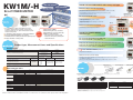
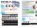
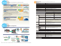
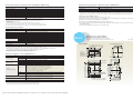
● Single-phase two-wire system
AKW1111
AKW1110
RS485
* Do not connect to EYUqw terminal.
They are connected internal.
P.OUT
RS485
E
9
10
11
12
13
7
14
8
9
10
3
4
5
6
7
2
3
4
P0
P1
P1
P0
Measured
voltage input
100-240V AC
Power supply
12
13
5
6
1
CT1
2
K
L
Series
*1
Measured
voltage input
Power supply
100-240VAC
50/60Hz
1
CT1
2
K
L
AKW1121
RS485
P.OUT
* Do not connect to YU terminal.
They are connected internal.
P. IN
E
8
9
10
11
12
13
14
6
7
KW1M
Eco-POWER METER
CT1
*1
ARCT1B316E
Power supply
side
1
CT1
N.C.
Power supply
side
2
Load side
1
11
0.1A
30VDC
0.1A
30VDC
Load side
E
8
* Do not connect to TY terminal.
They are connected internal.
P. IN
P.OUT
KW1M Series
KW1M, KW1M-H Terminal arrangement and Wiring diagrams
Simple and compact power meter
perfect for control panels
0.1A
30VDC
2
3
4
5
CT1
Power supply
side
N.C.
P1
P0
Measured
voltage input
100-240V AC
Power supply
1
Load side
1
CT1
2
K
L
● Single-phase three-wire/Three-phase three-wire system (CT is secondarily necessary)
AKW1110
AKW1111
RS485
* Do not connect to EUqw terminal.
They are connected internal.
P.OUT
RS485
E
9
10
11
12
13
7
14
8
9
10
0.1A
30VDC
1
2
3
4
11
5
6
7
1
CT1 CT2
2
3
4
P0
P2
Measured
voltage input
CT1
RR1
NS2
CT2
TT3
K
Power supply
side
P1
Load side
Power supply
side
P1
100-240V AC
Power supply
12
13
5
6
0.1A
30VDC
L
P0
CT1 CT2
P2
Measured
voltage input
Power supply
100-240VAC
50/60Hz
CT1
RR1
Load side
E
8
* Do not connect to Y terminal.
They are connected internal.
P. IN
P.OUT
NS 2
CT2
TT3
K
L
AKW1121
RS485
P.OUT
* Do not connect to U terminal.
They are connected internal.
P. IN
E
8
9
10
11
12
13
14
6
7
0.1A
30VDC
2
3
4
5
CT1 CT2
Power supply
side
N.C.
P1
100-240V AC
Power supply
P0
P2
Measured
voltage input
CT1
Load side
1
RR1
NS2
CT2
TT3
K
L
● Three-phase four-wire system (CT is thirdly necessary)
AKW1111
AKW1121
P. IN
RS485
P.OUT
E
9
10
11
12
8
0.1A
30VDC
1
2
3
4
Power supply
side
P1
Power supply
100-240VAC
50/60Hz
R1
S2
10
11
12
13
14
6
7
0.1A
30VDC
6
P2
1
2
3
4
5
CT1 CT2 CT3
N.C.
P3
P1
Measured
voltage input
CT1
CT2
CT3
T3
N4
9
CT1 CT2 CT3
5
P0
P. IN
E
13
K
L
Power supply
side
8
Load side
7
P0
100-240V AC
Power supply
P2
P3
Measured
voltage input
CT1
R
S
CT2
T
K
N
CT3
L
KW1M-H Eco-POWER METER
SD memory card type
Load side
P.OUT
RS485
KW1M Eco-POWER METER
Standard type
! "#$$ %
&!
'$$"
( '$$"#
-year
warranty
. /-! /5 6 04/78& 3 9
./0&12$3 4&
)
*+, !- !
* %
AUDIN - 8, avenue de la malle - 51370 Saint Brice Courcelles - Tel : 03.26.04.20.21 - Fax : 03.26.04.28.20 - Web : http: www.audin.fr - Email : [email protected]
KW1M/-H
Thin and compact
KW1M-H Eco-POWER METER SD memory card type
Easy installation
Energy saving
Automatic locking of electricity usage amount
(Current consumption of main unit)
Eco-POWER METER
● Measurement data locked at intervals of 1, 10, 15, 30, and 60 minutes (selectable)
● Screen display of past logs for each month, day or hour (max. 1.5 years)
● Data reading using SD memory cards
CT connects easily.
Direct input with 400 VAC system
● Direct input with 400 VAC system or 3-phase,
4-wire system voltage
● Support for overseas markets and large-scale factories
that use high voltage.
AKW1111
AKW1110
AKW1121
Output terminal (selection)
(1) Integrated power pulse
(2) Excess current and power notification
(3) Standby power notification
KW1M-H
only
Highly visible
LCD
Write
measurement data
to SD/SDHC card.
Simultaneous power/pulse measurement
AKW1121
(SD and SDHC cards
sold separately)
KW1M-H
only
● Simultaneous power and pulse measurement
● Use “visualization” to grasp current status (measurement)
● Inherits features of KW1M.
● Internal memory (SD memory card reading)
● Built-in battery (for clock and log data backup)
● Addition of measurement items.
In addition to simple measurement of voltage, current, power and
integrated electrical power, etc., output of warning signals is possible
using the “warning setting”.
Features of
● 50 mm thickness makes it perfect for control panel installations.
KW1M-H
● Both screw and DIN rail installation (easy installation).
● Switchable between electrical power and electricity charge usage.
● Display of calculated CO2 value possible.
• Power factor, frequency, and pulse counter
• Integrated electrical power by month/day/hour
• Calendar timer function
Product type, Measurement items and Specifications
Product type
KW1M Eco-POWER METER
Standard type
KW1M Eco-POWER METER Standard type
KW1M-H Eco-POWER METER SD memory card type
Phase and wire system
Single-phase two-wire system
Single-phase three-wire system
Three-phase three-wire system
Measured voltage input
Model No.
100/200 VAC
AKW1110
100/200/400 VAC
(Select with setting mode)
AKW1111
100/200/400 VAC
(Select with setting mode)
AKW1121
Operating power
supply
Measured current
input
100 to 240 VAC,
50/60 Hz
50A
100A
250A
400A
Three-phase four-wire system (For AKW1111, AKW1121 only)
Current transformer
(sold separately)
Terminal type
Dedicated CT type
[5 A, 50 A (common)/
100 A/250 A/400 A]
Screw terminal
(M3 “+/−” screw)
or
(M3.5 “+/−” screw)*1
Screw mounting
● Easy network construction
Notification function (external output)
● Standby power warning: Warning lets you find standby power of devices and equipment
(For AKW1111, AKW1121).
● Excess power and current warning: Warning lets you find overuse of power or current.
● Mounting rail
(applicable for DIN and
IEC standards)
Integrated electrical power (Active)
Current
Voltage
R current
S current*2
T current
R (RS) voltage
S (RT) voltage*2
T (TS) voltage
Electricity charge*1
Converted CO2 value
Power factor*2
Pulse counter*2
2
kW
kWh/MWh
A
A
A
V
V
V
–
kg-CO2
–
Frequency*2
Hour meter
Unit
ON time
OFF time
Hz
h (Hour)
h (Hour)
–
AKW1110
Includes MEWTOCOL/MODBUS protocol
Measurement items
Item
Keys on front for easy setting
Switch display items
Single-phase two-wire/Single-phase three-wire/Three-phase three-wire system
Single-phase two-wire/Single-phase three-wire/Three-phase three-wire/
Three-phase four-wire system(*) (*only AKW1111)
*1 The M3.5 “+/−” screws are only for the operation voltage and voltage input terminals (P0, P1, P2, and P3).
Instantaneous electrical power (Active)
DIN rail installation
Safe and easy installation M3 screws
and terminal protective cover
Direct input with 100/200 VAC system (AKW1110)
Direct input with 400 VAC system (AKW1111)
Common
Product name
Built-in backup
battery
(replaceable)
AKW1111
● Fastening plate
● Backup battery
*For holding DIN rail
*Included with main unit
(For AKW1121)
Data display range
0.00 to 9999.99
0.00 to 9999.99MWh
0.00 to 9999999.99kWh (When 9-digit display)
0.0 to 6000.0
0.0 to 6000.0
0.0 to 6000.0
0.0 to 99999.9
0.0 to 99999.9
0.0 to 99999.9
0.00 to 999999
0.00 to 999999
0.00 to 1.00 [Identify leading phase (–) or lagging phase]
(Only in range of phase angle θ = –90° to +90°)
47.5 to 63.0
0.0 to 99999.9
0.0 to 99999.9
0 to 999999
*1 Eco-POWER METER is designed chiefly for managing energy saving. It is not intended to be used for billing.
*2 For AKW1111, AKW1121 only
AUDIN - 8, avenue de la malle - 51370 Saint Brice Courcelles - Tel : 03.26.04.20.21 - Fax : 03.26.04.28.20 - Web : http: www.audin.fr - Email : [email protected]
Length: 1 m
aluminum
AT8-DLA1
● Dedicated current transformer*
ATA806
AFPG804
A CT is not included with the product. Please order in accordance with the type of power distribution system you will be measuring.
(Even if you will be using a secondary 5A CT, you will need an AKW4801C.)
AKW4801C
AKW4802C
AKW4803C
AKW4804C
Product name
Rated primary current
Model No.
Dedicated current transformer for 5 A/50 A
5A/50A
AKW4801C
Mounting rail
Dedicated current transformer for 100 A
100A
AKW4802C
Fastening plate
Dedicated current transformer for 250 A
250A
AKW4803C
Dedicated current transformer for 400 A
400A
AKW4804C
* Dedicated current transformers (CT), AKW4801C, AKW4802C, AKW4803C, AKW4804C,
are dedicated for low voltage under 440V system. They can not be used for high voltage
circuit. In case measuring high voltage circuit, make a 2-step construction by
combination of a commercial CT of secondary side current 5A for high voltage and the
dedicated CT for 5A (AKW4801C).
Product name
Backup battery (included)
Description
Model No.
Rail for holding DIN rail terminal socket
AT8-DLA1
Plate for holding DIN rail
ATA4806
For clock function
(AKW1121: For memory backup function)
AFPG804
3
KW1M/-H
Thin and compact
KW1M-H Eco-POWER METER SD memory card type
Easy installation
Energy saving
Automatic locking of electricity usage amount
(Current consumption of main unit)
Eco-POWER METER
● Measurement data locked at intervals of 1, 10, 15, 30, and 60 minutes (selectable)
● Screen display of past logs for each month, day or hour (max. 1.5 years)
● Data reading using SD memory cards
CT connects easily.
Direct input with 400 VAC system
● Direct input with 400 VAC system or 3-phase,
4-wire system voltage
● Support for overseas markets and large-scale factories
that use high voltage.
AKW1111
AKW1110
AKW1121
Output terminal (selection)
(1) Integrated power pulse
(2) Excess current and power notification
(3) Standby power notification
KW1M-H
only
Highly visible
LCD
Write
measurement data
to SD/SDHC card.
Simultaneous power/pulse measurement
AKW1121
(SD and SDHC cards
sold separately)
KW1M-H
only
● Simultaneous power and pulse measurement
● Use “visualization” to grasp current status (measurement)
● Inherits features of KW1M.
● Internal memory (SD memory card reading)
● Built-in battery (for clock and log data backup)
● Addition of measurement items.
In addition to simple measurement of voltage, current, power and
integrated electrical power, etc., output of warning signals is possible
using the “warning setting”.
Features of
● 50 mm thickness makes it perfect for control panel installations.
KW1M-H
● Both screw and DIN rail installation (easy installation).
● Switchable between electrical power and electricity charge usage.
● Display of calculated CO2 value possible.
• Power factor, frequency, and pulse counter
• Integrated electrical power by month/day/hour
• Calendar timer function
Product type, Measurement items and Specifications
Product type
KW1M Eco-POWER METER
Standard type
KW1M Eco-POWER METER Standard type
KW1M-H Eco-POWER METER SD memory card type
Phase and wire system
Single-phase two-wire system
Single-phase three-wire system
Three-phase three-wire system
Measured voltage input
Model No.
100/200 VAC
AKW1110
100/200/400 VAC
(Select with setting mode)
AKW1111
100/200/400 VAC
(Select with setting mode)
AKW1121
Operating power
supply
Measured current
input
100 to 240 VAC,
50/60 Hz
50A
100A
250A
400A
Three-phase four-wire system (For AKW1111, AKW1121 only)
Current transformer
(sold separately)
Terminal type
Dedicated CT type
[5 A, 50 A (common)/
100 A/250 A/400 A]
Screw terminal
(M3 “+/−” screw)
or
(M3.5 “+/−” screw)*1
Screw mounting
● Easy network construction
Notification function (external output)
● Standby power warning: Warning lets you find standby power of devices and equipment
(For AKW1111, AKW1121).
● Excess power and current warning: Warning lets you find overuse of power or current.
● Mounting rail
(applicable for DIN and
IEC standards)
Integrated electrical power (Active)
Current
Voltage
R current
S current*2
T current
R (RS) voltage
S (RT) voltage*2
T (TS) voltage
Electricity charge*1
Converted CO2 value
Power factor*2
Pulse counter*2
2
kW
kWh/MWh
A
A
A
V
V
V
–
kg-CO2
–
Frequency*2
Hour meter
Unit
ON time
OFF time
Hz
h (Hour)
h (Hour)
–
AKW1110
Includes MEWTOCOL/MODBUS protocol
Measurement items
Item
Keys on front for easy setting
Switch display items
Single-phase two-wire/Single-phase three-wire/Three-phase three-wire system
Single-phase two-wire/Single-phase three-wire/Three-phase three-wire/
Three-phase four-wire system(*) (*only AKW1111)
*1 The M3.5 “+/−” screws are only for the operation voltage and voltage input terminals (P0, P1, P2, and P3).
Instantaneous electrical power (Active)
DIN rail installation
Safe and easy installation M3 screws
and terminal protective cover
Direct input with 100/200 VAC system (AKW1110)
Direct input with 400 VAC system (AKW1111)
Common
Product name
Built-in backup
battery
(replaceable)
AKW1111
● Fastening plate
● Backup battery
*For holding DIN rail
*Included with main unit
(For AKW1121)
Data display range
0.00 to 9999.99
0.00 to 9999.99MWh
0.00 to 9999999.99kWh (When 9-digit display)
0.0 to 6000.0
0.0 to 6000.0
0.0 to 6000.0
0.0 to 99999.9
0.0 to 99999.9
0.0 to 99999.9
0.00 to 999999
0.00 to 999999
0.00 to 1.00 [Identify leading phase (–) or lagging phase]
(Only in range of phase angle θ = –90° to +90°)
47.5 to 63.0
0.0 to 99999.9
0.0 to 99999.9
0 to 999999
*1 Eco-POWER METER is designed chiefly for managing energy saving. It is not intended to be used for billing.
*2 For AKW1111, AKW1121 only
Length: 1 m
aluminum
AT8-DLA1
● Dedicated current transformer*
ATA806
AFPG804
A CT is not included with the product. Please order in accordance with the type of power distribution system you will be measuring.
(Even if you will be using a secondary 5A CT, you will need an AKW4801C.)
AKW4801C
AKW4802C
AKW4803C
AKW4804C
Product name
Rated primary current
Model No.
Dedicated current transformer for 5 A/50 A
5A/50A
AKW4801C
Mounting rail
Dedicated current transformer for 100 A
100A
AKW4802C
Fastening plate
Dedicated current transformer for 250 A
250A
AKW4803C
Dedicated current transformer for 400 A
400A
AKW4804C
* Dedicated current transformers (CT), AKW4801C, AKW4802C, AKW4803C, AKW4804C,
are dedicated for low voltage under 440V system. They can not be used for high voltage
circuit. In case measuring high voltage circuit, make a 2-step construction by
combination of a commercial CT of secondary side current 5A for high voltage and the
dedicated CT for 5A (AKW4801C).
Product name
Backup battery (included)
Description
Model No.
Rail for holding DIN rail terminal socket
AT8-DLA1
Plate for holding DIN rail
ATA4806
For clock function
(AKW1121: For memory backup function)
AFPG804
3
AUDIN - 8, avenue de la malle - 51370 Saint Brice Courcelles - Tel : 03.26.04.20.21 - Fax : 03.26.04.28.20 - Web : http: www.audin.fr - Email : [email protected]
Specifications
For details, please refer to the KW1M/KW1M-H Eco-POWER METER user’s manual.
● Main unit
All software tool can be downloaded*, free of charge, from the website.
Panasonic Electric Works website http://panasonic-electric-works.net/ac *Customer registration is required before you download.
Item
Specifications
Rated operating voltage
For easy power “visualization”
KW View (Power display tool)
Verification
Electrical
power
CO2
1h
Fixed
Charge
For KW1M-H
(1) Simply load the CSV file on your SD or SDHC card into your PC.
You can then display the data as a graph by month, day and hour, and print it out.
(2) Using easy operation, you can manage Eco-POWER METER data for up to 99 units.
(3) Graph display is in 1 hour units (fixed).
For easy “visualization” of data collected in the DLU*
Electrical
power
KW Watcher (tool for checking power measurement operation)
CO2
Temperature
Management
Charge
Primary
units
KW View
Flow
1h
Fixed
100 to 240V AC
Rated frequency
50/60Hz common
Rated power consumption
AKW1110: 6 VA (240V AC at 25°C) / AKW1111, AKW1121: 8 VA (240V AC at 25°C)
Allowable operating voltage range
85 to 264V AC (85% to 110% of rated operating voltage)
Allowable momentary power-off time
10ms
Ambient temperature
–10 to +50°C (–25°C to +70°C at storage)
Ambient humidity
30 to 85%RH (at 20°C non-condensing)
Display method
LCD with backlight
Upper section: Green, 4-digit, 16-segment, Letter height 6.5 mm
Lower section: Amber, 6-digit, 7-segment, Letter height 7.5 mm
Power failure memory method
EEP-ROM (more than 100,000 overwrite)
Size
75 × 90 × 50 mm
Weight
KW1M: approx. 170g / KW1M-H: approx. 180g
● Power input specifications
(1) Please use in situations where the DLU* and Eco-POWER METER
are used together.
(2) Gather power, water amount, temperature, primary unit and air flow
amount measurement data collected in the DLU* to easily create
graphs and numerical displays, etc.
Specifications
Item
AKW1110
AKW1111, AKW1121
Single-phase two-wire, Single-phase three-wire,
Three-phase three-wire (common)
Single-phase two-wire, Single-phase three-wire,
Three-phase three-wire, Three-phase four-wire
(common)
Rating
Single-phase two-wire: 0 to 220V AC (Line voltage)
Single-phase three-wire: 0 to 110V AC (Phase voltage)
Three-phase three-wire: 0 to 220V AC (Line voltage)
Single-phase two-wire: 0 to 440V AC (Line voltage)
Single-phase three-wire: 0 to 220V AC (Phase voltage)
Three-phase three-wire: 0 to 440V AC (Line voltage)
Three-phase four-wire: 0 to 254V AC (Phase voltage)
Allowance
Up to 120% of rated input voltage
Allowable measurement voltage
Single-phase two-wire: 0 to 264V AC (Line voltage)
Single-phase three-wire: 0 to 132V AC (Phase voltage)
Three-phase three-wire: 0 to 264V AC (Line voltage)
VT ratio
1.00 to 99.99 (Set with setting mode)
* A transformer for measuring (VT) is required when measuring loads that exceed the nominal input
voltage (AKW1111 and AKW1121 are 440 VAC, and AKW1110 is 220 VAC).
Please use a commercially available VT with nominal secondary measurement voltage of 110 V.
For low voltage circuits, secondary grounding is not required for the VT (transformer for measuring
instruments) or the CT (current sensor).
Primary side rating
<In case using dedicated CT>
5A/50A/100A/250A/400A (Select with setting mode)
<In case using commercial CT with secondary side 5A>
1 to 4000 A (Set with setting mode)
* Use a commercial CT with secondary side current of 5A when measure 400A or more.
* Accuracy coverage: 10 to 100% of rated current of CT
Cut-off current
1.0 to 50.0%F.S. (Select with setting mode)
Cut-off voltage
Within 5% of rated voltage (within voltage value sought by rated voltage × 0.05 × VT ratio) (fixed)
Current threshold for hour meter
1.0 to 100.0%F.S.
KW Watcher
Phase and wire system
(Measuring instruments such as other sensors will be required for flow amount, temperature and primary units.)
(3) Measurement is in 1 hour units (fixed).
*DLU is the abbreviation for Web Datalogger Unit.
KW Monitor (Data collection software for Eco-POWER METER)
Analysis
CO2
(1) Measuring can be selected among 1 s, 5 s, 10 s, 15 s,
30 s, 60 s, 1 m, 5 m, 10 m, 15 m, 30 m, and 60 m units.*1
(2) Electrical power can be measured either integrated or
instantaneous.
Current
ON
time
Power
factor
Frequency
Counter
Demand
Time
set
OK
Voltage
Uses only MEWTOCOL
Charge
*1
Input
voltage
KW Monitor
Input
current
Special
functions
System configuration
Equipment embedded power surveillance
Accuracy
(without
error in CT
and VT)
Power display tool
For integration into freezers and refrigerators, molding machines,
mounting machines, and thermostatic chambers, etc.
KW View
KW1M-H
Eco-POWER METER
Indication
accuracy
Integrated/
Instantaneous
power
For easy “visualization” of data collected from Eco-POWER METER
Instantaneous electric power
Integrated electric power
Voltage
Current
Electricity charge
Calculated CO2 value
Hour meter
±2.5% F.S. +1digit (at 20°C, rated input, rated frequency, power factor 1)
* Accuracy coverage: 10 to 100% of rated current of CT
±0.01%+1digit (at 20°C) (In case power on start or current energizing: ±0.01%+1s+1 digit, at 20°C)
Temperature characteristics
±1.5% F.S. /10°C ±1digit (Range of –10 to 50°C for rated input, power factor 1)
Frequency characteristics
±1.5% F.S. ±1 digit (Frequency change±5% based on rated frequency, for rated input, power factor 1)
● Pulse input specifications (For AKW1111, AKW1121 only)
Item
Power “visualization” is easily
achieved by simply loading an
SD card into a PC.
Perfect for small system
energy control
Power surveillance of lighting and air conditioning of buildings, plants, and stores, etc.
Specifications
Input mode
Addition (Fixed)
Max. counting speed
2kHz/30Hz (Select with setting mode)
Pulse input
Min. input signal width: 0.25ms (When 2kHz selected)/16.7ms (When 30Hz selected)
ON : OFF ratio = 1 : 1
Input signal
Contact/No contact (open collector)
• Impedance when shorted: Max. 1kΩ
• Residual voltage when shorted: Max. 2V
• Impedance when open: Min. 100kΩ
Handle the energy saving obligations of schools, multiple stores, and buildings.
Building
Store
Web
Datalogger
Unit
Single-phase two-wire: 0 to 528V AC (Line voltage)
Single-phase three-wire: 0 to 264V AC (Phase voltage)
Three-phase three-wire: 0 to 528V AC (Line voltage)
Three-phase four-wire: 0 to 300V AC (Phase voltage)
Lights
Output mode
Prescale setting
HOLD (Over count)
Decimal point
Setting possible up to 3 digits after decimal point
Range
0.001 to 100.000 (Set with setting mode)
Air
conditioner
Plant
Tool for checking power
measurement operation
4
KW Watcher
AUDIN - 8, avenue de la malle - 51370 Saint Brice Courcelles - Tel : 03.26.04.20.21 - Fax : 03.26.04.28.20 - Web : http: www.audin.fr - Email : [email protected]
5
Specifications
For details, please refer to the KW1M/KW1M-H Eco-POWER METER user’s manual.
● Main unit
All software tool can be downloaded*, free of charge, from the website.
Panasonic Electric Works website http://panasonic-electric-works.net/ac *Customer registration is required before you download.
Item
Specifications
Rated operating voltage
For easy power “visualization”
KW View (Power display tool)
Verification
Electrical
power
CO2
1h
Fixed
Charge
For KW1M-H
(1) Simply load the CSV file on your SD or SDHC card into your PC.
You can then display the data as a graph by month, day and hour, and print it out.
(2) Using easy operation, you can manage Eco-POWER METER data for up to 99 units.
(3) Graph display is in 1 hour units (fixed).
For easy “visualization” of data collected in the DLU*
Electrical
power
KW Watcher (tool for checking power measurement operation)
CO2
Temperature
Management
Charge
Primary
units
KW View
Flow
1h
Fixed
100 to 240V AC
Rated frequency
50/60Hz common
Rated power consumption
AKW1110: 6 VA (240V AC at 25°C) / AKW1111, AKW1121: 8 VA (240V AC at 25°C)
Allowable operating voltage range
85 to 264V AC (85% to 110% of rated operating voltage)
Allowable momentary power-off time
10ms
Ambient temperature
–10 to +50°C (–25°C to +70°C at storage)
Ambient humidity
30 to 85%RH (at 20°C non-condensing)
Display method
LCD with backlight
Upper section: Green, 4-digit, 16-segment, Letter height 6.5 mm
Lower section: Amber, 6-digit, 7-segment, Letter height 7.5 mm
Power failure memory method
EEP-ROM (more than 100,000 overwrite)
Size
75 × 90 × 50 mm
Weight
KW1M: approx. 170g / KW1M-H: approx. 180g
● Power input specifications
(1) Please use in situations where the DLU* and Eco-POWER METER
are used together.
(2) Gather power, water amount, temperature, primary unit and air flow
amount measurement data collected in the DLU* to easily create
graphs and numerical displays, etc.
Specifications
Item
AKW1110
AKW1111, AKW1121
Single-phase two-wire, Single-phase three-wire,
Three-phase three-wire (common)
Single-phase two-wire, Single-phase three-wire,
Three-phase three-wire, Three-phase four-wire
(common)
Rating
Single-phase two-wire: 0 to 220V AC (Line voltage)
Single-phase three-wire: 0 to 110V AC (Phase voltage)
Three-phase three-wire: 0 to 220V AC (Line voltage)
Single-phase two-wire: 0 to 440V AC (Line voltage)
Single-phase three-wire: 0 to 220V AC (Phase voltage)
Three-phase three-wire: 0 to 440V AC (Line voltage)
Three-phase four-wire: 0 to 254V AC (Phase voltage)
Allowance
Up to 120% of rated input voltage
Allowable measurement voltage
Single-phase two-wire: 0 to 264V AC (Line voltage)
Single-phase three-wire: 0 to 132V AC (Phase voltage)
Three-phase three-wire: 0 to 264V AC (Line voltage)
VT ratio
1.00 to 99.99 (Set with setting mode)
* A transformer for measuring (VT) is required when measuring loads that exceed the nominal input
voltage (AKW1111 and AKW1121 are 440 VAC, and AKW1110 is 220 VAC).
Please use a commercially available VT with nominal secondary measurement voltage of 110 V.
For low voltage circuits, secondary grounding is not required for the VT (transformer for measuring
instruments) or the CT (current sensor).
Primary side rating
<In case using dedicated CT>
5A/50A/100A/250A/400A (Select with setting mode)
<In case using commercial CT with secondary side 5A>
1 to 4000 A (Set with setting mode)
* Use a commercial CT with secondary side current of 5A when measure 400A or more.
* Accuracy coverage: 10 to 100% of rated current of CT
Cut-off current
1.0 to 50.0%F.S. (Select with setting mode)
Cut-off voltage
Within 5% of rated voltage (within voltage value sought by rated voltage × 0.05 × VT ratio) (fixed)
Current threshold for hour meter
1.0 to 100.0%F.S.
KW Watcher
Phase and wire system
(Measuring instruments such as other sensors will be required for flow amount, temperature and primary units.)
(3) Measurement is in 1 hour units (fixed).
*DLU is the abbreviation for Web Datalogger Unit.
KW Monitor (Data collection software for Eco-POWER METER)
Analysis
CO2
(1) Measuring can be selected among 1 s, 5 s, 10 s, 15 s,
30 s, 60 s, 1 m, 5 m, 10 m, 15 m, 30 m, and 60 m units.*1
(2) Electrical power can be measured either integrated or
instantaneous.
Current
ON
time
Power
factor
Frequency
Counter
Demand
Time
set
OK
Voltage
Uses only MEWTOCOL
Charge
*1
Input
voltage
KW Monitor
Input
current
Special
functions
System configuration
Equipment embedded power surveillance
Accuracy
(without
error in CT
and VT)
Power display tool
For integration into freezers and refrigerators, molding machines,
mounting machines, and thermostatic chambers, etc.
KW View
KW1M-H
Eco-POWER METER
Indication
accuracy
Integrated/
Instantaneous
power
For easy “visualization” of data collected from Eco-POWER METER
Instantaneous electric power
Integrated electric power
Voltage
Current
Electricity charge
Calculated CO2 value
Hour meter
±2.5% F.S. +1digit (at 20°C, rated input, rated frequency, power factor 1)
* Accuracy coverage: 10 to 100% of rated current of CT
±0.01%+1digit (at 20°C) (In case power on start or current energizing: ±0.01%+1s+1 digit, at 20°C)
Temperature characteristics
±1.5% F.S. /10°C ±1digit (Range of –10 to 50°C for rated input, power factor 1)
Frequency characteristics
±1.5% F.S. ±1 digit (Frequency change±5% based on rated frequency, for rated input, power factor 1)
● Pulse input specifications (For AKW1111, AKW1121 only)
Item
Power “visualization” is easily
achieved by simply loading an
SD card into a PC.
Perfect for small system
energy control
Power surveillance of lighting and air conditioning of buildings, plants, and stores, etc.
Specifications
Input mode
Addition (Fixed)
Max. counting speed
2kHz/30Hz (Select with setting mode)
Pulse input
Min. input signal width: 0.25ms (When 2kHz selected)/16.7ms (When 30Hz selected)
ON : OFF ratio = 1 : 1
Input signal
Contact/No contact (open collector)
• Impedance when shorted: Max. 1kΩ
• Residual voltage when shorted: Max. 2V
• Impedance when open: Min. 100kΩ
Handle the energy saving obligations of schools, multiple stores, and buildings.
Building
Store
Web
Datalogger
Unit
Single-phase two-wire: 0 to 528V AC (Line voltage)
Single-phase three-wire: 0 to 264V AC (Phase voltage)
Three-phase three-wire: 0 to 528V AC (Line voltage)
Three-phase four-wire: 0 to 300V AC (Phase voltage)
Lights
Output mode
Prescale setting
HOLD (Over count)
Decimal point
Setting possible up to 3 digits after decimal point
Range
0.001 to 100.000 (Set with setting mode)
Air
conditioner
Plant
Tool for checking power
measurement operation
4
KW Watcher
5
AUDIN - 8, avenue de la malle - 51370 Saint Brice Courcelles - Tel : 03.26.04.20.21 - Fax : 03.26.04.28.20 - Web : http: www.audin.fr - Email : [email protected]
● Pulse output (transistor output) specifications (For AKW1111, AKW1121 only)
Item
● External memory specifications <SD memory card slot> (KW1M-H only)
Specifications
Number of output point
1 point
Insulation method
Optical coupler
Output type
Open collector
Output capacity
100mA 30V DC
Item
Specifications
Support media
SD memory card (256MB to 4GB)*6
Supported format standards
Compliant with SD and SDHC standards*7
*6 Operation verified maker: Panasonic Corporation
*7 To format SD memory cards, please download and use the formatting software available on the Panasonic website.
The file system on a SD memory card that was formatted using standard PC software does not comply with the SD memory card standard.
[Panasonic website ➝ Customer support ➝ SD/SDHC memory card page ➝ Software download list] http://panasonic.jp/support/sd_w/download
Pulse width
Approx. 100ms
ON state voltage drop
1.5V or less
OFF state leakage current
100µA or less
Pulse output unit
0.001/0.01/0.1/1/10/100kWh/Power alarm (AL-P)/Current alarm (AL-C)/Standby power alarm (AL-S)*1/
Counter (Cnt)*1 (Selectable with setting mode)
*1 For AKW1111, AKW1121 only
* We recommend the setting of minimum unit for pulse output for measurement shown as below.
Output pulse: 4 pulse or less per 1sec.
Calculation method
(Pulse output unit: value of PL-P) > (Max. measured power [kW]) / (3600 [s] x 4 [pulse/s])
Note 1: Count errors may occur if pulse output unit is set so that 4 or more pulses are output per 1 second.
Note 2: The connected counter or PLC may cause count errors if the OFF time of the pulse output unit is short.
<SD memory card handling cautions>
In the following cases, you may lose data saved on SD memory cards.
Panasonic Electric Works will bear absolutely no responsibility for loss of stored data or any resulting direct or indirect damages.
1) Erroneous use of SD memory cards by the user or a third part.
2) The SD memory card was affected by static electricity or electrical noise.
3) The card was removed or the main power was turned off while the SD memory card access lamp on the main unit was
flashing (data writing).
* We recommend that important data always be backed up to a separate medium.
● Communication specifications
Specifications
Protocol
MEWTOCOL/MODBUS (RTU) (selectable with setting mode)
Isolation status
Isolated with the internal circuit
Number of connected units
99 (max.)*2 *3
Transmission distance
1200m*1
KW1M-H SD memory card type AKW1121
KW1M Standard type AKW1110, AKW1111
38400/19200/9600/4800/2400bps (selectable with setting mode)
Transmission format
Data length
8bit/7bit (selectable with setting mode)*4
Parity
Not available / Odd number / Even number (selectable with setting mode)
Stop bit
1bit (fixed)
Communication method
Half-duplex
Synchronous system
Synchronous communication method
Ending resistance
Approx. 120Ω (built-in)
● Be sure to wire according to the terminal arrangement or wiring diagrams.
● For details, please refer to the KW1M/KW1M-H Eco-POWER METER user’s manual.
● KW1M, KW1M-H
*1 Please check with the actual devices when some commercial devices with RS485 interface are connected.
The number of connected devices, transmission distance, transmission speed may be different according to using transmission line.
*2 For RS485 converter on the computer side, we recommend SI-35 and SI-35USB (from LINE EYE Co., Ltd.).
*3 When using SI-35,SI-35USB or our PLC (which can be connected up to 99 units), up to 99 Eco-POWER METER can be connected.
In case using this system with the other devices, up to 31 Eco-POWER METER can be connected.
*4 With MODBUS (RTU) protocol, it works only with data length (8bit/7bit).
* Modbus Protocol is a communications protocol developed for PLCs by Modicon Inc.
File type 2
(difference value)*5
Save cycle
60 min. (on the hour) (fixed)
Save data
(Momentary value) Integrated electric power, Instantaneous electric power, Current, Voltage,
Power factor, Frequency, Pulse count value
Save data amount
24 records per file (max. approx. 1.5 years worth of data)
Save cycle
60 min. (on the hour) (fixed)
Save data
(Difference value) Integrated electric power, Pulse count value
Save data amount
24 records per file (max. approx. 1.5 years worth of data)
Save cycle
Select among 1 min, 5 min, 10 min, 15 min, 30 min, or 60 min.
(Saved timing)
When 1 min is selected: starts immediately after power is turned on
When 5 min is selected: 00, 05, 10, 15, 20, 25, 30... min after the hour
When 10 min is selected: 00, 10, 20, 30, 40, 50.min after the hour
When 15 min is selected: 00, 15, 30, 45 min after the hour
When 60 min is selected: 00 min after the hour
Save data
Integrated electric power, Instantaneous electric power, Current, Voltage, Power factor, Frequency,
Pulse count value
File type 3
(momentary value detail)*5
Save data amount
7,200 records
Main unit display
Integrated electric power by month (latest data covering 1.5 year period)/
Integrated electric power by day (latest data covering 1 month period)/
Integrated electric power by hour (latest data covering 24 hours period)
Calendar timer function
Time accuracy; monthly accuracy: ±240 sec. (at –10°C)/monthly accuracy: ±70 sec. (at 25°C)/
monthly accuracy: ±240 sec. (at 50°C)
Content of battery backup
Time measurement and log data retained
39.1 1.539
Connectors for
current transformer
(CT)
18.2
.717
11 11
.433 .433
2-M4 .157
50 1.969
47 1.850
25.1 .988
75 2.953
67 2.638
2-5 .197 dia.
(Mounting hole)
82 3.228
File type 1
(momentary value)*5
Specifications
67±0.5 2.638±.020
P=7.62 .300
90 3.543
Item
● Mounting hole dimensions
M3 .118 (Fastening torque: 0.5 to 0.6 N·m)
Terminal cover
(transparent)
● Memory specifications of main unit (KW1M-H only)
(unit: mm inch)
General tolerance: ±1.0 ±.039
82±0.5 3.228±.020
Transmission speed
8
.315
35.4 1.394
Conforming to RS485
71 2.795
60 2.362
58 2.283
Item
Interface
SD memory
card throttle*
*SD memory card throttle only applies
to SD card compatible type KW1M-H.
(54 2.126*)
(55 2.165*)
*When installing DIN rail
*5 With the setting mode you can select whether or not to save file types 1, 2 and 3, respectively.
All file types will be saved to memory if measuring is started without making this setting.
You can write to a SD memory card the log data that was saved to the internal memory.
6
AUDIN - 8, avenue de la malle - 51370 Saint Brice Courcelles - Tel : 03.26.04.20.21 - Fax : 03.26.04.28.20 - Web : http: www.audin.fr - Email : [email protected]
7
● Pulse output (transistor output) specifications (For AKW1111, AKW1121 only)
Item
● External memory specifications <SD memory card slot> (KW1M-H only)
Specifications
Number of output point
1 point
Insulation method
Optical coupler
Output type
Open collector
Output capacity
100mA 30V DC
Item
Specifications
Support media
SD memory card (256MB to 4GB)*6
Supported format standards
Compliant with SD and SDHC standards*7
*6 Operation verified maker: Panasonic Corporation
*7 To format SD memory cards, please download and use the formatting software available on the Panasonic website.
The file system on a SD memory card that was formatted using standard PC software does not comply with the SD memory card standard.
[Panasonic website ➝ Customer support ➝ SD/SDHC memory card page ➝ Software download list] http://panasonic.jp/support/sd_w/download
Pulse width
Approx. 100ms
ON state voltage drop
1.5V or less
OFF state leakage current
100µA or less
Pulse output unit
0.001/0.01/0.1/1/10/100kWh/Power alarm (AL-P)/Current alarm (AL-C)/Standby power alarm (AL-S)*1/
Counter (Cnt)*1 (Selectable with setting mode)
*1 For AKW1111, AKW1121 only
* We recommend the setting of minimum unit for pulse output for measurement shown as below.
Output pulse: 4 pulse or less per 1sec.
Calculation method
(Pulse output unit: value of PL-P) > (Max. measured power [kW]) / (3600 [s] x 4 [pulse/s])
Note 1: Count errors may occur if pulse output unit is set so that 4 or more pulses are output per 1 second.
Note 2: The connected counter or PLC may cause count errors if the OFF time of the pulse output unit is short.
<SD memory card handling cautions>
In the following cases, you may lose data saved on SD memory cards.
Panasonic Electric Works will bear absolutely no responsibility for loss of stored data or any resulting direct or indirect damages.
1) Erroneous use of SD memory cards by the user or a third part.
2) The SD memory card was affected by static electricity or electrical noise.
3) The card was removed or the main power was turned off while the SD memory card access lamp on the main unit was
flashing (data writing).
* We recommend that important data always be backed up to a separate medium.
● Communication specifications
Specifications
Protocol
MEWTOCOL/MODBUS (RTU) (selectable with setting mode)
Isolation status
Isolated with the internal circuit
Number of connected units
99 (max.)*2 *3
Transmission distance
1200m*1
KW1M-H SD memory card type AKW1121
KW1M Standard type AKW1110, AKW1111
38400/19200/9600/4800/2400bps (selectable with setting mode)
Transmission format
Data length
8bit/7bit (selectable with setting mode)*4
Parity
Not available / Odd number / Even number (selectable with setting mode)
Stop bit
1bit (fixed)
Communication method
Half-duplex
Synchronous system
Synchronous communication method
Ending resistance
Approx. 120Ω (built-in)
● Be sure to wire according to the terminal arrangement or wiring diagrams.
● For details, please refer to the KW1M/KW1M-H Eco-POWER METER user’s manual.
● KW1M, KW1M-H
*1 Please check with the actual devices when some commercial devices with RS485 interface are connected.
The number of connected devices, transmission distance, transmission speed may be different according to using transmission line.
*2 For RS485 converter on the computer side, we recommend SI-35 and SI-35USB (from LINE EYE Co., Ltd.).
*3 When using SI-35,SI-35USB or our PLC (which can be connected up to 99 units), up to 99 Eco-POWER METER can be connected.
In case using this system with the other devices, up to 31 Eco-POWER METER can be connected.
*4 With MODBUS (RTU) protocol, it works only with data length (8bit/7bit).
* Modbus Protocol is a communications protocol developed for PLCs by Modicon Inc.
File type 2
(difference value)*5
Save cycle
60 min. (on the hour) (fixed)
Save data
(Momentary value) Integrated electric power, Instantaneous electric power, Current, Voltage,
Power factor, Frequency, Pulse count value
Save data amount
24 records per file (max. approx. 1.5 years worth of data)
Save cycle
60 min. (on the hour) (fixed)
Save data
(Difference value) Integrated electric power, Pulse count value
Save data amount
24 records per file (max. approx. 1.5 years worth of data)
Save cycle
Select among 1 min, 5 min, 10 min, 15 min, 30 min, or 60 min.
(Saved timing)
When 1 min is selected: starts immediately after power is turned on
When 5 min is selected: 00, 05, 10, 15, 20, 25, 30... min after the hour
When 10 min is selected: 00, 10, 20, 30, 40, 50.min after the hour
When 15 min is selected: 00, 15, 30, 45 min after the hour
When 60 min is selected: 00 min after the hour
Save data
Integrated electric power, Instantaneous electric power, Current, Voltage, Power factor, Frequency,
Pulse count value
File type 3
(momentary value detail)*5
Save data amount
7,200 records
Main unit display
Integrated electric power by month (latest data covering 1.5 year period)/
Integrated electric power by day (latest data covering 1 month period)/
Integrated electric power by hour (latest data covering 24 hours period)
Calendar timer function
Time accuracy; monthly accuracy: ±240 sec. (at –10°C)/monthly accuracy: ±70 sec. (at 25°C)/
monthly accuracy: ±240 sec. (at 50°C)
Content of battery backup
Time measurement and log data retained
39.1 1.539
Connectors for
current transformer
(CT)
18.2
.717
11 11
.433 .433
2-M4 .157
50 1.969
47 1.850
25.1 .988
75 2.953
67 2.638
2-5 .197 dia.
(Mounting hole)
82 3.228
File type 1
(momentary value)*5
Specifications
67±0.5 2.638±.020
P=7.62 .300
90 3.543
Item
● Mounting hole dimensions
M3 .118 (Fastening torque: 0.5 to 0.6 N·m)
Terminal cover
(transparent)
● Memory specifications of main unit (KW1M-H only)
(unit: mm inch)
General tolerance: ±1.0 ±.039
82±0.5 3.228±.020
Transmission speed
8
.315
35.4 1.394
Conforming to RS485
71 2.795
60 2.362
58 2.283
Item
Interface
SD memory
card throttle*
*SD memory card throttle only applies
to SD card compatible type KW1M-H.
(54 2.126*)
(55 2.165*)
*When installing DIN rail
*5 With the setting mode you can select whether or not to save file types 1, 2 and 3, respectively.
All file types will be saved to memory if measuring is started without making this setting.
You can write to a SD memory card the log data that was saved to the internal memory.
6
7
AUDIN - 8, avenue de la malle - 51370 Saint Brice Courcelles - Tel : 03.26.04.20.21 - Fax : 03.26.04.28.20 - Web : http: www.audin.fr - Email : [email protected]
● Single-phase two-wire system
AKW1111
AKW1110
RS485
* Do not connect to EYUqw terminal.
They are connected internal.
P.OUT
RS485
E
9
10
11
12
13
7
14
8
9
10
3
4
5
6
7
2
3
4
P0
P1
P1
P0
Measured
voltage input
100-240V AC
Power supply
12
13
5
6
1
CT1
2
K
L
Series
*1
Measured
voltage input
Power supply
100-240VAC
50/60Hz
1
CT1
2
K
L
AKW1121
RS485
P.OUT
* Do not connect to YU terminal.
They are connected internal.
P. IN
E
8
9
10
11
12
13
14
6
7
KW1M
Eco-POWER METER
CT1
*1
ARCT1B316E
Power supply
side
1
CT1
N.C.
Power supply
side
2
Load side
1
11
0.1A
30VDC
0.1A
30VDC
Load side
E
8
* Do not connect to TY terminal.
They are connected internal.
P. IN
P.OUT
KW1M Series
KW1M, KW1M-H Terminal arrangement and Wiring diagrams
Simple and compact power meter
perfect for control panels
0.1A
30VDC
2
3
4
5
CT1
Power supply
side
N.C.
P1
P0
Measured
voltage input
100-240V AC
Power supply
1
Load side
1
CT1
2
K
L
● Single-phase three-wire/Three-phase three-wire system (CT is secondarily necessary)
AKW1110
AKW1111
RS485
* Do not connect to EUqw terminal.
They are connected internal.
P.OUT
RS485
E
9
10
11
12
13
7
14
8
9
10
0.1A
30VDC
1
2
3
4
11
5
6
7
1
CT1 CT2
2
3
4
P0
P2
Measured
voltage input
CT1
RR1
NS2
CT2
TT3
K
Power supply
side
P1
Load side
Power supply
side
P1
100-240V AC
Power supply
12
13
5
6
0.1A
30VDC
L
P0
CT1 CT2
P2
Measured
voltage input
Power supply
100-240VAC
50/60Hz
CT1
RR1
Load side
E
8
* Do not connect to Y terminal.
They are connected internal.
P. IN
P.OUT
NS 2
CT2
TT3
K
L
AKW1121
RS485
P.OUT
* Do not connect to U terminal.
They are connected internal.
P. IN
E
8
9
10
11
12
13
14
6
7
0.1A
30VDC
2
3
4
5
CT1 CT2
Power supply
side
N.C.
P1
100-240V AC
Power supply
P0
P2
Measured
voltage input
CT1
Load side
1
RR1
NS2
CT2
TT3
K
L
● Three-phase four-wire system (CT is thirdly necessary)
AKW1111
AKW1121
P. IN
RS485
P.OUT
E
9
10
11
12
8
0.1A
30VDC
1
2
3
4
Power supply
side
P1
Power supply
100-240VAC
50/60Hz
R1
S2
10
11
12
13
14
6
7
0.1A
30VDC
6
P2
1
2
3
4
5
CT1 CT2 CT3
N.C.
P3
P1
Measured
voltage input
CT1
CT2
CT3
T3
N4
9
CT1 CT2 CT3
5
P0
P. IN
E
13
K
L
Power supply
side
8
Load side
7
P0
100-240V AC
Power supply
P2
P3
Measured
voltage input
CT1
R
S
CT2
T
K
N
CT3
L
KW1M-H Eco-POWER METER
SD memory card type
Load side
P.OUT
RS485
KW1M Eco-POWER METER
Standard type
! "#$$ %
&!
'$$"
( '$$"#
-year
warranty
. /-! /5 6 04/78& 3 9
./0&12$3 4&
)
*+, !- !
* %
AUDIN - 8, avenue de la malle - 51370 Saint Brice Courcelles - Tel : 03.26.04.20.21 - Fax : 03.26.04.28.20 - Web : http: www.audin.fr - Email : [email protected]