1
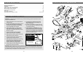
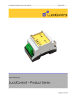
®
ORDERING REPLACEMENT PARTS
If you encounter any difficulties with this product or if you have to order replacement parts, contact the ICON
Fitness Lifestyle Ltd. office, or write:
ICON Fitness Lifestyle Ltd.
Greenwich House
223 North Street
Sheepscar
Leeds LS7 2AA
West Yorkshire
Model No. PFEX97572
Serial No.
Tel: Country Code: 0345-089009
Fax: 01789-440798
• The MODEL NUMBER of the product (PFEX97572).
Serial
Number
Decal
• The NAME of the product (PROFORM® 975s).
• The SERIAL NUMBER of the product (see the front cover of this manual).
• The KEY NUMBER and DESCRIPTION of the part(s) (see the PART LIST on page 14 of this manual).
QUESTIONS?
As a manufacturer, we are committed to providing complete
customer satisfaction. If you
have questions, or find that there
are missing or damaged parts,
we will guarantee you complete
satisfaction through our
Customer Service Department.
Please CALL:
0345-089009
Or WRITE:
ICON Fitness Lifestyle Ltd.
Greenwich House
223 North Street
Sheepscar
Leeds LS7 2AA
West Yorkshire
Patent Pending
CAUTION
PROFORM® is a registered trademark of ICON Health & Fitness, Inc.
Part No. 149376 R0998A
Printed in China © 1998 ICON Health & Fitness, Inc.
Read all precautions and instructions in this manual before using
this equipment. Keep this manual
for future reference.
USER'S MANUAL
TABLE OF CONTENTS
EXPLODED DRAWING—Model No. PFEX97572
IMPORTANT PRECAUTIONS . . . . . . . . . . . . . . . . . . . . . . . . . . . . . . . . . . . . . . . . . . . . . . . . . . . . . . . . . . . . .2
BEFORE YOU BEGIN . . . . . . . . . . . . . . . . . . . . . . . . . . . . . . . . . . . . . . . . . . . . . . . . . . . . . . . . . . . . . . . . . . .3
ASSEMBLY . . . . . . . . . . . . . . . . . . . . . . . . . . . . . . . . . . . . . . . . . . . . . . . . . . . . . . . . . . . . . . . . . . . . . . . . . . .4
HOW TO USE THE PROFORM® 975S . . . . . . . . . . . . . . . . . . . . . . . . . . . . . . . . . . . . . . . . . . . . . . . . . . . . . . .8
HOW TO USE THE PULSE SENSOR . . . . . . . . . . . . . . . . . . . . . . . . . . . . . . . . . . . . . . . . . . . . . . . . . . . . . .11
MAINTENANCE AND STORAGE . . . . . . . . . . . . . . . . . . . . . . . . . . . . . . . . . . . . . . . . . . . . . . . . . . . . . . . . . .12
CONDITIONING GUIDELINES . . . . . . . . . . . . . . . . . . . . . . . . . . . . . . . . . . . . . . . . . . . . . . . . . . . . . . . . . . . .13
PART LIST . . . . . . . . . . . . . . . . . . . . . . . . . . . . . . . . . . . . . . . . . . . . . . . . . . . . . . . . . . . . . . . . . . . . . . . . . . .14
EXPLODED DRAWING . . . . . . . . . . . . . . . . . . . . . . . . . . . . . . . . . . . . . . . . . . . . . . . . . . . . . . . . . . . . . . . . .15
ORDERING REPLACEMENT PARTS . . . . . . . . . . . . . . . . . . . . . . . . . . . . . . . . . . . . . . . . . . . . . . . .Back Cover
R0998A
7
9
6
10
13
8
14
22
67
67
34
21
11
33
5
14
22
IMPORTANT PRECAUTIONS
4
2
25
41
WARNING: To reduce the risk of serious injury, read the following important precautions before
using the PROFORM® 975s.
22
26
25
12
31
5
48
1. Read all instructions in this manual before
using the 975s.
9. If you feel pain or dizziness at any time
while exercising, stop immediately and
begin cooling down.
2. It is the responsibility of the owner to ensure
that all users of the 975s are adequately
informed of all precautions. Use the 975s
only as described in this manual.
28
30
22
22
50
10. The 975s is intended for in-home use only.
Do not use the 975s in a commercial, rental,
or institutional setting.
22
22
22
26
26
61
29
55
53
54
13
32
52 36
38
42
56
68
37
40 39
1
3. Use the 975s indoors on a level surface.
Keep the 975s away from moisture and
dust. Place a mat under the 975s to protect
the floor or carpet.
11. CAUTION DECAL PLACEMENT: The decal
shown below has been placed on the 975s.
If the decal is missing, or if it is not legible,
please call our Customer Service Department
to order a free replacement decal. Apply the
decal in the location shown.
4. Inspect and tighten all parts regularly.
Replace any worn parts immediately.
51
39
48
10
65
23
64
47
29 46
30 47
46
43
Do not allow children on or
around machine.
6. The 975s should not be used by persons
weighing more than 250 pounds.
Keep hands and feet away
from moving parts and contact
points.
7. Wear appropriate clothing when exercising;
do not wear loose clothing that could
become caught on the 975s. Always wear
athletic shoes when using the 975s.
Read owner's manual and
follow instructions.
24
63
19
44
5. Keep children under the age of 12 and pets
away from the 975s at all times.
15
23
57
22
59
52
70
3
35
58
27
36
37
38
22
39
45
22
62
60
20
16
48
Decal shown at
75% actual size
17
71
48
8. Always keep your back straight when using
the 975s. Do not arch your back.
18
62
66
WARNING: Before beginning this or any exercise program, consult your physician. This is especially important for persons over the age of 35 or persons with pre-existing health problems. Read
all instructions before using. ICON assumes no responsibility for personal injury or property damage sustained by or through the use of this product.
69
72
24
2
49
66
17
48
18
15
35
22
PART LIST—Model No. PFEX97572
Key No. Qty.
1
2
3
4
5
6
7
8
9
10
11
12
13
14
15
16
17
18
19
20
21
22
23
24
25
26
27
28
29
30
31
32
33
34
35
36
37
38
1
1
1
1
2
1
1
1
1
1
4
4
1
4
1
1
2
4
2
1
6
21
2
8
3
3
1
1
1
1
1
1
2
1
4
2
2
2
Description
R0998A
Key No. Qty.
Frame
Upright
Seat Frame
Handlebar
Pulse Grip
Left Side Shield
Right Side Shield
Console
Resistance Knob
Resistance Cable/Control
M5 x 30mm Screw
M5 Nut
Reed Switch/Wire
M6 x 25mm Hex Head Screw
Backrest
Seat
Seat Handle
M6 x 38mm Button Head Bolt
Foam Handle Grip
1” x 3” Endcap
Tree Fastener
#8 x 5/8” Screw
#8 x 3/8” Screw
M6 x 16mm Hex Head Screw
M10 x 25mm Button Head Screw
M10 Split Washer
Left Pedal Strap
Right Pedal
Crank/Pulley
Bearing Assembly
Right Pedal Strap
Magnet
M4 x32mm Screw
M4 x 16mm Screw
Rubber Bumper
M8 Flanged Hex Nut
M6 Eyebolt
Adjustment Bracket
39
40
41
42
43
44
45
46
47
48
49
50
51
52
53
54
55
56
57
58
59
60
61
62
63
64
65
66
67
68
69
70
71
72
#
#
#
4
2
2
1
1
1
1
2
2
5
1
1
1
2
4
1
1
1
1
1
1
1
1
2
1
1
1
4
4
1
1
4
4
4
1
1
1
Description
M6 Nut
M10 Washer
Extension Wire
Flywheel
10mm x 13mm Spacer
Flywheel Axle
Left Pedal
M10 x 52mm Button Head Screw
Wheel
2” x 3” Endcap
1 1/2” x 3” Endcap
Cable Clamp
M6 x 56mm Bolt
M8 Split Washer
#8 Flat Washer
Clamp Bolt
Clamp Nut
Resistance Hook
Resistance Spring
Magnet Bracket
M8 x 65mm Hex Head Bolt
M8 Nylon Locknut
Drive Belt
1 1/4” Round Endcap
2” x 4” Endcap
Frame Bushing
Seat Frame Bushing
M6 Nylon Locknut
M6 Split Washer
Lock Knob
Seat Bracket
M10 x 105mm Button Head Bolt
M10 Flat Washer
M10 Nylon Locknut
User’s Manual
4mm Allen Wrench
5.5mm Allen Wrench
BEFORE YOU BEGIN
Thank you for selecting the innovative PROFORM®
975s. The PROFORM 975s offers a unique form of
low-impact exercise that offers greater cardiovascular
benefits and increased muscle toning. The 975s
features adjustable resistance to let you tailor your
exercise to the level that’s perfect for you. And when
you’re not exercising, the 975s can be folded for
compact storage.
after reading the manual, please contact our
Customer Service Department. To help us assist you,
please note the product model number and serial
number when calling. The model number is
PFEX97572. The serial number can be found on a
decal attached to the 975s (see the front cover of this
manual for the location of the decal).
Before reading further, please look at the drawing
below and familiarise yourself with the parts that are
labelled.
For your benefit, read this manual carefully before
you use the PROFORM 975s. If you have questions
Console
Handlebar with
Pulse Sensor
Backrest
Seat
FRONT
Seat Frame
Pedal
Strap
Seat Handle
BACK
Pedal
PFEX9757
LEFT SIDE
Note: “#” indicates a non-illustrated part. Specifications are subject to change without notice. See the back cover
of this manual for information about ordering replacement parts.
14
3
ASSEMBLY
CONDITIONING GUIDELINES
Place all parts of the PROFORM® 975s in a cleared area and remove the packing materials. Do not dispose of
the packing materials until assembly is completed.
The following guidelines will help you to plan your
exercise program. Remember that proper nutrition and
adequate rest are essential for successful results.
Assembly requires the included tools and your own adjustable spanner
During the first few months of your exercise program,
keep your heart rate near the low end of your training
zone as you exercise. After a few months of regular
exercise, your heart rate can be increased gradually
until it is near the middle of your training zone as you
exercise.
.
PART CHART
Use the part drawings below to identify the small parts used in assembly. The number in parenthesis below
each drawing refers to the key number of the part. The second number refers to the quantity used in assembly.
Note: Some small parts may have been pre-attached for shipping. If a part is not in the parts bag, check
to see if it has been pre-assembled.
WARNING: Before beginning this or any
exercise program, consult your physician.
This is especially important for individuals
over the age of 35 or individuals with preexisting health problems.
To measure your heart rate, use the pulse sensor in
the handlebar. You can also measure your pulse by
placing two fingers
on your wrist. Stop
exercising and
take a six-second
heartbeat count.
Multiply the result
by ten to find your
heart rate. (A sixsecond count is
used because
your heart rate
drops quickly
when you stop
exercising.) If your heart rate is too high, decrease the
intensity of your exercise. If your heart rate is too low,
increase the intensity of your exercise.
WHY EXERCISE?
Exercise has proven essential for good health and
general well-being. Regular participation in a wellrounded exercise program results in a stronger and
more efficient heart, improved respiratory function,
increased stamina and endurance, better weight management and body fat control, increased ability to deal
with stress, and greater self-esteem and confidence.
M6 Split Washer (67)–4
M6 Nylon Locknut (66)–4
M10 Split Washer (26)–3
M10 Flat Washer (71)–4
M10 Nylon Locknut (72)–4
M4 x 16mm Screw (34)—1
EXERCISE INTENSITY
To maximize the benefits of exercising, it is important
to exercise with the proper intensity. The proper intensity level can be found by using your heart rate as a
guide. For effective aerobic exercise, your heart rate
should be maintained at a level between 70% and
85% of your maximum heart rate as you exercise.
This is known as your training zone. You can find
your training zone in the table below. Training zones
are listed according to age and physical condition.
WORKOUT GUIDELINES
A well-rounded workout includes the following three
phases:
A warm-up phase, lasting 5 to 10 minutes. Begin with
slow, controlled stretches, and progress to more rhythmic stretches. This will increase the body temperature,
heart rate, and circulation in preparation for strenuous
exercise.
TRAINING ZONE (BEATS/MIN.)
AGE
#8 x 5/8” Screw (22)–4
M6 x 16mm Hex Head Screw (24)–8
M6 x 38mm Button Head Bolt (18)–4
M6 x 25mm Hex Head Screw (14)–4
M10 x 25mm Button Head Screw (25)–3
M10 x 105mm Button Head Bolt (70)–4
4
UNCONDITIONED CONDITIONED
20
138–167
133–162
25
136–166
132–160
30
135–164
130–158
35
134–162
129–156
40
132–161
127–155
45
131–159
125–153
50
129–156
124–150
55
127–155
122–149
60
126–153
121–147
65
125–151
119–145
70
123–150
118–144
75
122–147
117–142
80
120–146
115–140
85
118–144
114–139
A cardiovascular phase, including 20 to 30 minutes
of exercising with your heart rate in your training zone.
A cool-down phase, consisting of 5 to 10 minutes of
stretching. Thorough stretching offsets muscle contractions and other problems caused when you stop
exercising suddenly. Stretching for increased flexibility
is often most effective during this phase. This phase
should leave you relaxed and comfortably tired.
To maintain or improve your condition, complete three
workouts each week, with at least one day of rest
between workouts. After a few months of regular exercise, you may complete up to five workouts each
week, if desired. Find the best time of day for your
workouts, and then stick with it.
Remember, the key to success is to make exercise a
regular and enjoyable part of your everyday life.
13
MAINTENANCE AND STORAGE
Inspect and tighten all parts of the PROFORM® 975s
regularly. The 975s can be cleaned with a soft, damp
cloth. To prevent damage to the console, keep liquids
away and keep the console out of direct sunlight.
1
68
3
HOW TO STORE THE PROFORM® 975S
If the console does not function properly, the batteries
should be replaced. To replace the batteries, refer to
assembly step 11 on page 7.
When the PROFORM® 975s is
1
not in use, it can
68
be folded for
compact storage.
Refer to the
drawing at the
right. Loosen the
Lock Knob (68)
3
on the right side
of the Frame (1).
Slide the Seat
Frame (3) as far
into the Frame
as it will go. Tighten the Lock Knob. Store the PROFORM® 975s indoors, away from moisture and dust.
CRANK ADJUSTMENT
Slotted
Bearing
Nut
35
1
driver in one of the slots in the Slotted Bearing Nut.
Lightly tap the screwdriver with a hammer to turn the
Slotted Bearing Nut counterclockwise until the arms
are no longer loose. Do not overtighten the Slotted
Bearing Nut. When the Slotted Bearing Nut is properly tightened, tighten the Crank Nut.
BATTERY REPLACEMENT
If the arms of the
Crank (14)
become loose,
they should be
tightened in
order to prevent
excessive wear.
Loosen the
Crank Nut (35)
on the left arm of
the Crank. Place
the end of a
standard screw-
1. Loosen the Lock Knob (68) on the right side of the
Frame (1). Slide the Seat Frame (3) out until it
stops. Tighten the Lock Knob.
14
2. Attach the Upright (2) to the Frame (1) with three
M10 x 25mm Button Head Screws (25) and three
M10 Split Washers (26). Be careful not to pinch
the Reed Switch Wire (13) or the Resistance
Cable (10).
2
2
25
26
26
25
25
1
3. Route both Extension Wires (41) up through the
Upright (2) as shown.
3
14
Attach the Handlebar (4) to the Upright (2) with two
M6 x 25mm Hex Head Screws (14) and two M6 Split
Washers (67), but do not tighten the Screws yet.
Make sure that the Screws are threaded into the
indicated holes. Note: Two additional Screws will
be attached in step 5.
4. Connect the Reed Switch Wire (13) and the two
Extension Wires (41) to the corresponding wires on
the Console (8).
67
67
41
4
14
2
4
8
9
Console
Wires
If your Console (8) has a earthing wire, attach it to
the Upright (2) with an M4 x 16mm Screw (34).
Earthing
Wire
34
41
Next, attach the Console (8) to the Upright (2) with
four #8 x 5/8” Screws (22).
13
10
22
Press the Resistance Knob (9) onto the Resistance
Control (10). Be sure that the mark on the Knob is
correctly aligned.
12
13
10
2
22
5
5. Finish attaching the Handlebar (4) to the Upright (2)
with two more M6 x 25mm Hex Head Screws (14)
and two more M6 Split Washers (67). Tighten all
four Hex Head Screws.
5
HOW TO USE THE PULSE SENSOR
14
The convenient pulse sensor allows you to measure
your heart rate periodically. You can measure your
heart rate before you begin exercising, during your
workout, and again when you finish.
67
67
To use the pulse
sensor, first
make sure that
the power is
turned on. Stop
exercising, rest
both feet on the
floor, and place
your hands on
Metal
the metal conContacts
tacts. Your
palms must be
resting on the
inner contacts and your fingers must be touching the
outer contacts. Avoid moving your hands. After a
moment, the heart indicator in the PULSE display will
flash and your heart rate will be shown. For the most
accurate heart rate reading, continue to hold the contacts for about 15 seconds.
4
14
2
6. Attach the Seat Bracket (69) to the Seat Frame (3)
with four M10 x 105mm Button Head Bolts (70), four
M10 Flat Washers (71), and four M10 Nylon
Locknuts (72).
70
6
69
3
71
• If an “H” appears in the PULSE display, then the
pulse sensor received too much pulse information to
accurately calculate your pulse. Let go of the metal
contacts; then place your hands on the contacts
again. Your palms must be resting on the inner contacts and your fingers must be touching the outer
contacts.
• Do not hold the metal contacts too tightly; doing so
may interfere with heart rate readings.
• Do not move your hands while you hold the metal
contacts; your muscle movement may interfere with
heart rate readings.
• For the most accurate heart rate reading, wait for
about 15 seconds.
71
72
7. Attach the Seat (16) to the Seat Bracket (69) with
four M6 x 16mm Hex Head Screws (24).
• If an “L” appears in the PULSE display, then the
pulse sensor received too little pulse information to
accurately calculate your pulse. Let go of the metal
contacts; then place your hands on the contacts
again. Your palms must be resting on the inner contacts and your fingers must be touching the outer
contacts.
HAND PULSE SENSOR TROUBLE-SHOOTING
7
• For optimal performance of the pulse sensor, keep
the metal contacts clean. The contacts can be
cleaned with a soft cloth—never use alcohol,
abrasives, or chemicals.
• Avoid moving your hands while using the pulse sensor. Excessive movement may interfere with heart
rate readings. If the pulse sensor is not used correctly, the heart indicator will flash repeatedly in the
PULSE display but your heart rate will not be shown.
16
69
24
8. Attach a Seat Handle (17) to the Seat Bracket (69)
with two M6 x 38mm Button Head Bolts (18) and
two M6 Nylon Locknuts (66).
8
17
Attach the other Seat Handle (17) to the Seat
Bracket (69) in the same manner.
69
66
17
6
18
11
• Distance (DIST)—This mode shows the total number of miles you have cycled, up to 999. The display
will then reset to zero and continue counting.
If you selected a
Target
pacer program, two
Pace
indicators on the
P.A.C.E.R. track will
Actual
light. The indicator
Pace
on the inner track
will show your actual
pace. The indicator
on the outer track
will move around the track at the programmed
pace. As you exercise, adjust your pace so that
the indicators on the inner and outer tracks
remain even. As the program progresses, the target pace will change periodically; as the target
pace changes, you should also adjust your pace.
Important: The target pace is a goal pace. Your
actual pace may be slower than the target
pace, especially during the first few months of
your exercise program. Be sure to exercise at
a pace that is comfortable for you.
• Laps—This mode shows the number of quarter-mile
laps you have completed.
• Calories (CAL)—This mode shows the approximate
number of calories you have burned.
STEP-BY-STEP CONSOLE OPERATION
Before the console can be operated, the batteries
must be installed. (See assembly step 11 on page 7
for installation instructions.) Follow the steps below to
operate the console.
1
Turn on the power
To turn on the
power, press the
on/reset button or
simply begin exercising. When the
power is turned on,
the entire display
will appear for two seconds. The console will then
be ready for use. Note: If batteries were just
installed, the power will already be on.
2
4
When the power is
turned on, the console will scan
through the five
modes automatically.
A flashing mode indiMode Indicator
cator will show which
mode is currently displayed. When the Laps mode is displayed, an “L”
will also appear. If desired, the display can be
reset by pressing the on/reset button.
Select one of the three pacer programs or the
manual mode
When the power is
first turned on, the
console will be in
the manual mode.
To select one of the
pacer programs,
repeatedly press
the program button.
The program indicator will show
which program you
have selected. The
programs will be selected in the following order:
the manual mode, the 6 MPH/30 RPM program,
the 12 MPH/60 RPM program, and the 18 MPH/
90 RPM program. Note: Once you select a pacer
program, you can reselect the manual mode by
repeatedly pressing the program button.
3
Follow your progress with the monitor modes
The PROFORM
975s also features
an innovative handgrip pulse sensor.
The pulse display
allows you to monitor
your heart rate during your workout. To use the
pulse sensor, see page 11.
®
5
9. Attach the Backrest (15) to the Seat Bracket (69)
with four M6 x 16mm Hex Head Screws (24).
9
15
69
24
10. Identify the Left Pedal (45) (there is an “L” on the
Left Pedal for identification). Using an adjustable
wrench, tighten the Left Pedal counterclockwise into
the left arm of the Crank (29).
10
27
Tighten the Right Pedal (not shown) clockwise into
the right arm of the Crank (29).
45
Adjust the Pedal Strap (27) on the Left Pedal (45) to
the desired position. Press the Pedal Strap onto the
adjustment tab on the Left Pedal.
Tab
29
Adjust the Pedal Strap on the Right Pedal (not
shown) in the same manner.
11. The Console (8) requires either two or three “AA”
batteries (not included); alkaline batteries are
recommended. Open the battery cover (not shown)
on the back of the Console. Press the batteries into
the battery clip. Make sure that the negative (–)
ends of the batteries are touching the springs.
Close the battery cover. Note: If the battery clip
holds three batteries, you must insert three batteries.
11
8
Batteries
Turn off the power
To turn off the power, simply wait for about six
minutes. If the pedals are not moved and the
console buttons are not pressed for six minutes,
the power will turn off automatically.
Battery
Clip
Begin your workout
If you selected the manual mode, one indicator on
the inner P.A.C.E.R. track will light. As you exercise, this indicator will move around the quartermile track.
12. Make sure that all parts are properly tightened before you use the PROFORM ® 975s.
10
7
HOW TO USE THE PROFORM® 975S
HOW TO ADJUST THE POSITION OF THE SEAT
FRAME
DIAGRAM OF THE CONSOLE
HOW TO ADJUST THE PEDAL STRAPS
To adjust each Pedal Strap (27), first pull the end of
the Pedal Strap off the adjustment tab on the Pedal
(45). Align a different hole in the Pedal Strap with the
adjustment tab. Press the Pedal Strap onto the
adjustment tab.
The Seat Frame (3) can be adjusted to the position
that is the most comfortable for you. To adjust the
Seat Frame, first loosen the Lock Knob (68) on the
right side of the Frame (1). Slide the Seat Frame forward or backward to the desired position. Tighten the
Lock Knob.
27
1
Note: If there is a thin
sheet of clear plastic on
the face of the console,
remove it.
68
Adjustment Tab
45
HOW TO ADJUST THE PEDALLING RESISTANCE
3
The pedalling
8
resistance can
be adjusted
9
with the
Resistance
Knob (9) located on the
Console (8). To
increase the
resistance, turn
the Resistance Knob clockwise; to decrease the resistance, turn the Resistance Knob counterclockwise.
DESCRIPTION OF THE CONSOLE
tors even. Important: The target pace is a goal
pace. Your actual pace may be slower than the target pace, especially during the first few months of
your exercise program. Be sure to exercise at a
pace that is comfortable for you.
The innovative console offers a manual mode and
three pacer programs. The pacer programs are
designed to help you achieve your exercise goals by
pacing your exercise. The programs include an 18
MPH/90 RPM program, a 12 MPH/60 RPM program,
and a 6 MPH/30 RPM program. The console also features five monitor modes that provide continuous exercise feedback. Note: On some consoles the programs are listed in MPH and on others in RPM.
Both sets of programs are identical.
The graphs on the left side of the console show how
the target pace will change during each program (see
the drawing above). Each graph is divided into ten
columns, and each column represents 1/10 of a mile.
The bars in each column show what the target pace
will be during that 1/10 of a mile. For example, in the
first column of the 12 MPH/60 RPM graph, there is
one bar. This shows that during the first 1/10 of a mile
in this program, the target pace will be 6 MPH (30
RPM). In the second column, there are two bars, indicating that the pace is now 12 MPH (60 RPM).
HOW THE PACER PROGRAMS OPERATE
When you use a
Actual
Target
pacer program, an
Pace
Pace
indicator will light
on each track of
the P.A.C.E.R.
display. The outer
track shows a target pace; the inner
track will show
your actual pace.
The target pace
will change periodically during the 18 MPH/90 RPM
and 12 MPH/60 RPM programs; as the target pace
changes, simply adjust your pace to keep both indica-
8
DESCRIPTION OF THE MONITOR MODES
The five monitor modes provide continuous exercise
feedback. The modes are described below.
• Speed—This mode shows your pace, in miles per
hour.
• Time—This mode counts the length of time you
have exercised. Note: If you stop exercising for ten
seconds or longer, the time mode will pause.
9