1
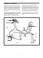
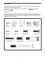
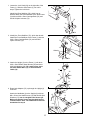
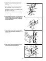
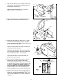
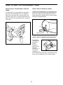
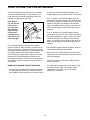
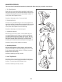
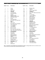
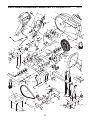
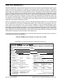
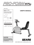
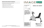
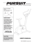
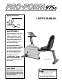
®
Model No. PFCCEX97573
Serial No.
USER'S MANUAL
Serial
Number
Decal
QUESTIONS?
As a manufacturer, we are committed to providing complete
customer satisfaction. If you
have questions, or if there are
missing or damaged parts, we
will guarantee complete satisfaction through direct assistance from our factory.
TO AVOID UNNECESSARY
DELAYS, PLEASE CALL DIRECT
TO OUR TOLL-FREE CUSTOMER
HOT LINE. The trained technicians on our customer hot line
will provide immediate assistance, free of charge to you.
CUSTOMER HOT LINE:
1-888-936-4266
Mon.–Fri., 8h00–18h30 EST
Eastern Standard Time (excluding holidays)
Patent Pending
CAUTION
Read all precautions and instructions in this manual before using
this equipment. Keep this manual
for future reference.
Visit our website at
www.proform.com
new products, prizes,
fitness tips, and much more!
TABLE OF CONTENTS
IMPORTANT PRECAUTIONS . . . . . . . . . . . . . . . . . . . . . . . . . . . . . . . . . . . . . . . . . . . . . . . . . . . . . . . . . . . . . . . .2
BEFORE YOU BEGIN . . . . . . . . . . . . . . . . . . . . . . . . . . . . . . . . . . . . . . . . . . . . . . . . . . . . . . . . . . . . . . . . . . . . . .3
ASSEMBLY . . . . . . . . . . . . . . . . . . . . . . . . . . . . . . . . . . . . . . . . . . . . . . . . . . . . . . . . . . . . . . . . . . . . . . . . . . . . . . .4
HOW TO USE THE RECUMBENT BIKE . . . . . . . . . . . . . . . . . . . . . . . . . . . . . . . . . . . . . . . . . . . . . . . . . . . . . . . .8
HOW TO USE THE PULSE SENSOR . . . . . . . . . . . . . . . . . . . . . . . . . . . . . . . . . . . . . . . . . . . . . . . . . . . . . . . . . .9
MAINTENANCE AND STORAGE . . . . . . . . . . . . . . . . . . . . . . . . . . . . . . . . . . . . . . . . . . . . . . . . . . . . . . . . . . . . .12
CONDITIONING GUIDELINES . . . . . . . . . . . . . . . . . . . . . . . . . . . . . . . . . . . . . . . . . . . . . . . . . . . . . . . . . . . . . . .13
PART LIST . . . . . . . . . . . . . . . . . . . . . . . . . . . . . . . . . . . . . . . . . . . . . . . . . . . . . . . . . . . . . . . . . . . . . . . . . . . . . .16
EXPLODED DRAWING . . . . . . . . . . . . . . . . . . . . . . . . . . . . . . . . . . . . . . . . . . . . . . . . . . . . . . . . . . . . . . . . . . . .17
CUSTOMER RECORD . . . . . . . . . . . . . . . . . . . . . . . . . . . . . . . . . . . . . . . . . . . . . . . . . . . . . . . . . . . . . . . . . . . . .18
ORDERING REPLACEMENT PARTS . . . . . . . . . . . . . . . . . . . . . . . . . . . . . . . . . . . . . . . . . . . . . . . . . . . . . . . . .19
LIMITED WARRANTY . . . . . . . . . . . . . . . . . . . . . . . . . . . . . . . . . . . . . . . . . . . . . . . . . . . . . . . . . . . . . . .Back Page
IMPORTANT PRECAUTIONS
WARNING: To reduce the risk of serious injury, read the following important precautions before
using the recumbent bike.
1. Read all instructions in this manual before
using the recumbent bike.
8. Always keep your back straight when using
the recumbent bike. Do not arch your back.
2. It is the responsibility of the owner to ensure
that all users of the recumbent bike are adequately informed of all precautions. Use the
recumbent bike only as described in this
manual.
9. If you feel pain or dizziness at any time
while exercising, stop immediately and
begin cooling down.
10. The recumbent bike is intended for in-home
use only. Do not use the recumbent bike in
a commercial, rental, or institutional setting.
3. Use the recumbent bike indoors on a level
surface. Keep the recumbent bike away
from moisture and dust. Place a mat under
the recumbent bike to protect the floor or
carpet.
11. CAUTION DECAL PLACEMENT: The decal
shown below has been placed on the
recumbent bike. If the decal is missing, or if
it is not legible, please call our Customer
Service Department toll-free at 1-888-9364266 to order a free replacement decal.
Apply the decal in the location shown.
4. Inspect and tighten all parts regularly.
Replace any worn parts immediately.
5. Keep children under the age of 12 and pets
away from the recumbent bike at all times.
Do not allow children on or
around machine.
6. The recumbent bike should not be used by
persons weighing more than 250 pounds.
Keep hands and feet away
from moving parts and contact
points.
7. Wear appropriate clothing when exercising;
do not wear loose clothing that could
become caught on the recumbent bike.
Always wear athletic shoes when using the
recumbent bike.
Read owner's manual and
follow instructions.
Decal shown at 75% actual size
WARNING: Before beginning this or any exercise program, consult your physician. This is especially important for persons over the age of 35 or persons with pre-existing health problems. Read
all instructions before using. ICON assumes no responsibility for personal injury or property damage sustained by or through the use of this product.
2
BEFORE YOU BEGIN
Thank you for selecting the innovative PROFORM®
975s recumbent bike. The recumbent bike offers a
unique form of low-impact exercise that offers greater
cardiovascular benefits and increased muscle toning.
And the recumbent bike features adjustable resistance to let you tailor your exercise to the level that’s
perfect for you.
through Friday, 8 a.m. until 6:30 p.m. Eastern
Standard Time (excluding holidays). To help us assist
you, please mention the product model number and
serial number when calling. The model number is
PFCCEX97573. The serial number can be found on a
decal attached to the recumbent bike (see the front
cover of this manual for the location of the decal).
For your benefit, read this manual carefully before
you use the recumbent bike. If you have additional
questions, please call our Customer Service
Department toll-free at 1-888-936-4266, Monday
Before reading further, please look at the drawing
below and familiarize yourself with the parts that are
labeled.
Console
Handlebar with
Pulse Sensor
Backrest
Seat
FRONT
Seat Frame
Pedal
Strap
Seat Handle
BACK
Pedal
PFEX9757
LEFT SIDE
3
ASSEMBLY
Place all parts of recumbent bike in a cleared area and remove the packing materials. Do not dispose of the
packing materials until assembly is completed.
Assembly requires the included tools and your own adjustable wrench
screwdriver
.
and phillips
PART CHART
Use the part drawings below to identify the small parts used in assembly. The number in parenthesis below
each drawing refers to the key number of the part. The second number refers to the quantity used in assembly.
Note: Some small parts may have been pre-attached for shipping. If a part is not in the parts bag, check
to see if it has been pre-assembled.
M6 Split
Washer (67)–4
M10 Flat
Washer (71)–4
M10 Split
Washer (26)–3
M4 x 16mm
Screw (34)—1
M6 x 38mm Button
Head Bolt (18)–4
#8 x 5/8”
Screw (22)–4
M6 Nylon
Locknut (66)–4
M6 x 16mm Hex
Head Screw (24)–8
M10 x 25mm Button
Head Screw (25)–3
M6 x 25mm Hex
Head Screw (14)–4
M10 x 58mm Carriage Bolt (74)–4
M10 x 105mm Button Head Bolt (70)–4
4
M10 Nylon
Locknut (72)–8
1. Loosen the Lock Knob (68) on the right side of the
Frame (1). Slide the Seat Frame (3) out until it
stops. Tighten the Lock Knob.
68
1
3
1
Identify the Rear Stabilizer (76), which has no
wheels. Attach the Rear Stabilizer to the Seat Frame
(3) with two M10 x 58mm Carriage Bolts (74) and
two M10 Nylon Locknuts (72).
72
72
76
74
2. Identify the Front Stabilizer (75), which has wheels.
Attach the Front Stabilizer to the Frame (1) with two
M10 x 58mm Carriage Bolts (74) and two M10
Nylon Locknuts (72).
2
72
1
Wheels
75
74
3. Attach the Upright (2) to the Frame (1) with three
M10 x 25mm Button Head Screws (25) and three
M10 Split Washers (26). Be careful not to pinch
the Reed Switch Wire (13) or the Resistance
Cable (10).
3
2
25
26
26
25
25
13
10
1
4. Route both Adapters (73) up through the Upright (2)
as shown.
4
Attach the Handlebar (4) to the Upright (2) with two
M6 x 25mm Hex Head Screws (14) and two M6 Split
Washers (67), but do not tighten the Screws yet.
Make sure that the Screws are threaded into the
indicated holes. Note: Two additional Screws will
be attached in step 6.
5
14
67
67
14
2
73
4
5. Connect the Reed Switch Wire (13) and the two
Adapters (73) to the corresponding wires on the
Console (8).
5
8
9
Console
Wires
If your Console (8) has a ground wire, attach it to
the Upright (2) with an M4 x 16mm Screw (34).
Ground
Wire
34
73
Next, attach the Console (8) to the Upright (2) with
four #8 x 5/8” Screws (22).
13
10
22
Press the Resistance Knob (9) onto the Resistance
Control (10). Be sure that the mark on the Knob is
correctly aligned.
2
22
6. Finish attaching the Handlebar (4) to the Upright (2)
with two more M6 x 25mm Hex Head Screws (14)
and two more M6 Split Washers (67). Tighten all
four Hex Head Screws.
6
14
67
67
4
14
2
7. Attach the Seat Bracket (69) to the Seat Frame (3)
with four M10 x 105mm Button Head Bolts (70), four
M10 Flat Washers (71), and four M10 Nylon
Locknuts (72).
70
7
69
3
71
72
8. Attach the Seat (16) to the Seat Bracket (69) with
four M6 x 16mm Hex Head Screws (24).
8
71
16
69
24
6
9. Attach a Seat Handle (17) to the Seat Bracket (69)
with two M6 x 38mm Button Head Bolts (18) and
two M6 Nylon Locknuts (66).
9
17
Attach the other Seat Handle (17) to the Seat
Bracket (69) in the same manner.
69
66
18
17
10. Attach the Backrest (15) to the Seat Bracket (69)
with four M6 x 16mm Hex Head Screws (24).
10
15
69
24
11. Identify the Left Pedal (45) (there is an “L” on the
Left Pedal for identification). Using an adjustable
wrench, tighten the Left Pedal counterclockwise into
the left arm of the Crank (29).
11
27
29
Tighten the Right Pedal (not shown) clockwise into
the right arm of the Crank (29).
45
Adjust the Left Pedal Strap (27) on the Left Pedal
(45) to the desired position. Press the Pedal Strap
onto the adjustment tab on the Left Pedal.
Tab
Adjust the Pedal Strap on the Right Pedal (not
shown) in the same manner.
12
12. The Console (8) requires either two or three “AA”
batteries (not included); alkaline batteries are
recommended. Open the battery cover (not shown)
on the back of the Console. Press the batteries into
the battery clip. Make sure that the negative (–)
ends of the batteries are touching the springs.
Close the battery cover. Note: If the battery clip
holds three batteries, you must insert three batteries.
8
Batteries
Battery
Clip
13. Make sure that all parts are properly tightened
before you use the recumbent bike. Note: There
may be some hardware left over after assembly is
completed.
7
HOW TO USE THE RECUMBENT BIKE
HOW TO ADJUST THE POSITION OF THE SEAT
FRAME
HOW TO ADJUST THE PEDAL STRAPS
To adjust each Pedal Strap (27, 31 [not shown]), first
pull the end of the Pedal Strap off the adjustment tab
on the Left Pedal (45). Align a different hole in the
Pedal Strap with the adjustment tab. Press the Pedal
Strap onto the adjustment tab.
The Seat Frame (3) can be adjusted to the position
that is the most comfortable for you. To adjust the
Seat Frame, first loosen the Lock Knob (68) on the
right side of the Frame (1). Slide the Seat Frame forward or backward to the desired position. Tighten the
Lock Knob.
1
27
68
Adjustment Tab
3
45
HOW TO ADJUST THE PEDALING RESISTANCE
The pedaling
8
resistance can
be adjusted
9
with the
Resistance
Knob (9) located on the
Console (8). To
increase the
resistance, turn
the Resistance Knob clockwise; to decrease the resistance, turn the Resistance Knob counterclockwise.
8
HOW TO USE THE PULSE SENSOR
The convenient pulse sensor allows you to measure
your heart rate periodically. You can measure your
heart rate before you begin exercising, during your
workout, and again when you finish.
Note: Before
you can use the
pulse sensor,
you must peel
the protective
vinyl covering
off the metal
contacts on the
front and rear of
each pulse grip.
ly, the heart indicator will flash repeatedly in the
PULSE display but your heart rate will not be shown.
• If an “L” appears in the PULSE display, then the
pulse sensor received too little pulse information to
accurately calculate your pulse. Let go of the metal
contacts; then place your hands on the contacts
again. Your palms must be resting on the inner contacts and your fingers must be touching the outer
contacts.
• If an “H” appears in the PULSE display, then the
pulse sensor received too much pulse information to
accurately calculate your pulse. Let go of the metal
contacts; then place your hands on the contacts
again. Your palms must be resting on the inner contacts and your fingers must be touching the outer
contacts.
Metal
Contacts
To use the pulse sensor, first make sure that the
power is turned on. Stop exercising, rest both feet on
the floor, and place your hands on the metal contacts.
Your palms must be resting on the inner contacts and
your fingers must be touching the outer contacts.
Avoid moving your hands. After a moment, the heart
indicator in the PULSE display will flash and your
heart rate will be shown. For the most accurate heart
rate reading, continue to hold the contacts for about
15 seconds.
• Do not hold the metal contacts too tightly; doing so
may interfere with heart rate readings.
• Do not move your hands while you hold the metal
contacts; your muscle movement may interfere with
heart rate readings.
• For the most accurate heart rate reading, wait for
about 15 seconds.
HAND PULSE SENSOR TROUBLE-SHOOTING
• For optimal performance of the pulse sensor, keep
the metal contacts clean. The contacts can be
cleaned with a soft cloth—never use alcohol,
abrasives, or chemicals.
• Avoid moving your hands while using the pulse sensor. Excessive movement may interfere with heart
rate readings. If the pulse sensor is not used correct-
9
DIAGRAM OF THE CONSOLE
Note: If there is a thin
sheet of clear plastic on
the face of the console,
remove it.
DESCRIPTION OF THE CONSOLE
The innovative console offers a manual mode and
three pacer programs. The pacer programs are
designed to help you achieve your exercise goals by
pacing your exercise. The programs include an 18
MPH/90 RPM program, a 12 MPH/60 RPM program,
and a 6 MPH/30 RPM program. The console also features five monitor modes that provide continuous
exercise feedback. Note: On some consoles the
programs are listed in MPH and on others in RPM.
Both sets of programs are identical.
HOW THE PACER PROGRAMS OPERATE
When you use a
pacer program, an
indicator will light
on each track of
the P.A.C.E.R.
display. The outer
track shows a target pace; the inner
track will show your
actual pace. The
target pace will
Actual
Pace
Target
Pace
change periodically during the 18 MPH/90 RPM and
12 MPH/60 RPM programs; as the target pace
changes, simply adjust your pace to keep both indicators even. Important: The target pace is a goal
pace. Your actual pace may be slower than the target pace, especially during the first few months of
your exercise program. Be sure to exercise at a
pace that is comfortable for you.
The graphs on the left side of the console show how
the target pace will change during each program (see
the drawing above). Each graph is divided into ten
columns, and each column represents 1/10 of a mile.
The bars in each column show what the target pace
will be during that 1/10 of a mile. For example, in the
first column of the 12 MPH/60 RPM graph, there is
one bar. This shows that during the first 1/10 of a mile
in this program, the target pace will be 6 MPH (30
RPM). In the second column, there are two bars, indicating that the pace is now 12 MPH (60 RPM).
DESCRIPTION OF THE MONITOR MODES
The five following monitor modes provide continuous
exercise feedback. The modes are described on the
next page.
10
• SPEED—This mode shows your pace, in miles per
hour.
3
If you selected the
Target
manual mode, one
Pace
indicator on the inner
P.A.C.E.R. track will
light. As you exerActual
Pace
cise, this indicator will
move around the
quarter-mile track.
If you selected a
pacer program, two indicators on the P.A.C.E.R.
track will light. The indicator on the inner track will
show your actual pace. The indicator on the outer
track will move around the track at the programmed pace. As you exercise, adjust your pace
so that the indicators on the inner and outer
tracks remain even. As the program progresses,
the target pace will change periodically; as the
target pace changes, you should also adjust your
pace. Important: The target pace is a goal
pace. Your actual pace may be slower than the
target pace, especially during the first few
months of your exercise program. Be sure to
exercise at a pace that is comfortable for you.
• TIME—This mode counts the length of time you
have exercised. Note: If you stop exercising for ten
seconds or longer, the time mode will pause.
• DIST (Distance) —This mode shows the total number of miles you have cycled, up to 999. The display
will then reset to zero and continue counting.
• LAPS—This mode shows the number of quartermile laps you have completed.
• CAL (Calories)—This mode shows the approximate
number of calories you have burned.
STEP-BY-STEP CONSOLE OPERATION
Before the console can be operated, batteries
must be installed. (See assembly step 12 on page 7
for installation instructions.) Follow the steps below to
operate the console.
1
Turn on the power
To turn on the power,
press the on/reset button or simply begin
exercising. When the
power is turned on, the
entire display will
appear for two seconds.
The console will then be ready for use. Note: If
batteries were just installed, the power will already
be on.
2
4
Follow your progress with the monitor modes
When the power is
turned on, the console
will scan through the
five modes automatically. A flashing mode
indicator will show
Mode Indicator
which mode is currently displayed. When the
Laps mode is displayed, an “L” will also appear. If
desired, the display can be reset by pressing the
on/reset button.
Select one of the three pacer programs or the
manual mode
When the power is
first turned on, the
console will be in the
manual mode. To
select one of the pacer
programs, repeatedly
press the program button. The program indicator will show which
program you have
selected. The programs will be selected
in the following order: the manual mode, the 6
MPH/30 RPM program, the 12 MPH/60 RPM program, and the 18 MPH/ 90 RPM program. Note:
Once you select a pacer program, you can reselect the manual mode by repeatedly pressing the
program button.
Begin your workout
The recumbent bike
also features an innovative handgrip pulse
sensor. The pulse display allows you to
monitor your heart
rate during your workout. To use the pulse sensor,
see page 9.
5
Turn off the power
To turn off the power, simply wait for about six
minutes. If the pedals are not moved and the
console buttons are not pressed for six minutes,
the power will turn off automatically.
11
MAINTENANCE AND STORAGE
Inspect and tighten all parts of the recumbent bike
regularly. The recumbent bike can be cleaned with a
soft, damp cloth. To prevent damage to the console,
keep liquids away and keep the console out of direct
sunlight.
driver in one of the slots in the slotted bearing nut.
Lightly tap the screwdriver with a hammer to turn the
slotted bearing nut counterclockwise until the arms
are no longer loose. Do not overtighten the slotted
bearing nut. When the slotted bearing nut is properly
tightened, tighten the crank nut.
BATTERY REPLACEMENT
HOW TO STORE THE RECUMBENT BIKE
If the console does not function properly, the batteries
should be replaced. To replace the batteries, refer to
assembly step 12 on page 7.
When the recumbent bike is not in
1
use, it can be
68
folded for compact storage.
Refer to the
drawing at the
right. Loosen the
Lock Knob (68)
3
on the right side
of the Frame (1).
Slide the Seat
Frame (3) as far
into the Frame as
it will go. Tighten the Lock Knob. Store the recumbent
bike indoors, away from moisture and dust.
CRANK ADJUSTMENT
If the arms of
the Crank (29)
become loose,
they should be
tightened in
order to prevent
excessive wear.
Loosen the
crank nut on the
left arm of the
Crank. Place
the end of a
standard screw-
Slotted
Bearing
Nut
Crank
Nut
29
12
CONDITIONING GUIDELINES
The following guidelines will help you to plan your
exercise program. Remember that proper nutrition and
adequate rest are essential for successful results.
During the first few months of your exercise program,
keep your heart rate near the low end of your training
zone as you exercise. After a few months of regular
exercise, your heart rate can be increased gradually
until it is near the middle of your training zone as you
exercise.
WARNING: Before beginning this or any
exercise program, consult your physician.
This is especially important for individuals
over the age of 35 or individuals with preexisting health problems.
To measure your
heart rate, use the
pulse sensor in the
handlebar. You can
also measure your
pulse by placing
two fingers on your
wrist. Stop exercising and take a sixsecond heartbeat
count. Multiply the result by ten to find your heart rate.
(A six-second count is used because your heart rate
drops quickly when you stop exercising.) If your heart
rate is too high, decrease the intensity of your exercise. If your heart rate is too low, increase the intensity
of your exercise.
WHY EXERCISE?
Exercise has proven essential for good health and
general well-being. Regular participation in a wellrounded exercise program results in a stronger and
more efficient heart, improved respiratory function,
increased stamina and endurance, better weight management and body fat control, increased ability to deal
with stress, and greater self-esteem and confidence.
EXERCISE INTENSITY
To maximize the benefits of exercising, it is important
to exercise with the proper intensity. The proper intensity level can be found by using your heart rate as a
guide. For effective aerobic exercise, your heart rate
should be maintained at a level between 70% and
85% of your maximum heart rate as you exercise.
This is known as your training zone. You can find
your training zone in the table below. Training zones
are listed according to age and physical condition.
WORKOUT GUIDELINES
A well-rounded workout includes three important parts:
A warm-up, lasting 5 to 10 minutes. Begin with slow,
controlled stretches, and progress to more rhythmic
stretches. This will increase the body temperature,
heart rate, and circulation in preparation for strenuous
exercise.
TRAINING ZONE (BEATS/MIN.)
AGE
A training zone exercise, including 20 to 30 minutes
of exercising with your heart rate in your training zone.
UNCONDITIONED CONDITIONED
20
138–167
133–162
25
136–166
132–160
30
135–164
130–158
35
134–162
129–156
40
132–161
127–155
45
131–159
125–153
50
129–156
124–150
55
127–155
122–149
60
126–153
121–147
65
125–151
119–145
70
123–150
118–144
75
122–147
117–142
80
120–146
115–140
85
118–144
114–139
A cool-down, consisting of 5 to 10 minutes of stretching. Thorough stretching offsets muscle contractions
and other problems caused when you stop exercising
suddenly. Stretching for increased flexibility is often
most effective during this phase. This phase should
leave you relaxed and comfortably tired.
To maintain or improve your condition, complete three
workouts each week, with at least one day of rest
between workouts. After a few months of regular exercise, you may complete up to five workouts each
week, if desired. Find the best time of day for your
workouts, and then stick with it.
Remember, the key to success is to make exercise a
regular and enjoyable part of your everyday life.
13
SUGGESTED STRETCHES
The correct form for several basic stretches is shown below. Move slowly as you stretch—never bounce.
1. Toe Touch Stretch
Stand with your knees bent slightly and slowly bend forward
from your hips. Allow your back and shoulders to relax as you
reach down toward your toes as far as possible. Hold for 15
counts, then relax. Repeat 3 times.
1
Stretches: Hamstrings, back of knees and back
2. Hamstring Stretch
2
Sit with one leg extended. Bring the sole of the opposite foot
toward you and rest it against the inner thigh of your extended
leg. Reach toward your toes as far as possible. Hold for 15
counts, then relax. Repeat 3 times for each leg.
Stretches: Hamstrings, lower back and groin
3. Calf/Achilles Stretch
With one leg in front of the other, reach forward and place
your hands against a wall. Keep your back leg straight and
your back foot flat on the floor. Bend your front leg, lean forward and move your hips toward the wall. Hold for 15 counts,
then relax. Repeat 3 times for each leg. To cause further
stretching of the achilles tendons, bend your back leg as well.
3
4
Stretches: Calves, achilles tendons and ankles
4. Quadriceps Stretch
With one hand against a wall for balance, reach back and
grasp one foot with your other hand. Bring your heel as close
to your buttocks as possible. Hold for 15 counts, then relax.
Repeat 3 times for each leg.
Stretches: Quadriceps and hip muscles
5. Inner Thigh Stretch
5
Sit with the soles of your feet together and your knees outward. Pull your feet toward your groin area as far as possible.
Hold for 15 counts, then relax. Repeat 3 times.
Stretches: Quadriceps and hip muscles
14
NOTES
15
PART LIST—Model No. PFCCEX97573
Key No. Qty.
1
2
3
4
5
6
7
8
9
10
11
12
13
14
15
16
17
18
19
20
21
22
23
24
25
26
27
28
29
30
31
32
33
34
35
36
37
38
39
40
1
1
1
1
2
1
1
1
1
1
4
4
1
4
1
1
2
4
2
1
6
19
2
8
3
3
1
1
1
1
1
1
2
1
4
2
2
2
4
2
Description
Key No. Qty.
Frame
Upright
Seat Frame
Handlebar
Pulse Grip
Left Side Shield
Right Side Shield
Console
Resistance Knob
Resistance Cable/Control
M5 x 30mm Screw
M5 Nut
Reed Switch/Wire
M6 x 25mm Hex Head Screw
Backrest
Seat
Seat Handle
M6 x 38mm Button Head Bolt
Foam Handle Grip
1” x 3” Endcap
Tree Fastener
#8 x 5/8” Screw
#8 x 3/8” Screw
M6 x 16mm Hex Head Screw
M10 x 25mm Button Head Screw
M10 Split Washer
Left Pedal Strap
Right Pedal
Crank/Pulley
Bearing Assembly
Right Pedal Strap
Magnet
M4 x 32mm Screw
M4 x 16mm Screw
Rubber Bumper
M8 Flanged Hex Nut
M6 Eyebolt
Adjustment Bracket
M6 Nut
M10 Washer
41
42
43
44
45
46
47
48
49
50
51
52
53
54
55
56
57
58
59
60
61
62
63
64
65
66
67
68
69
70
71
72
73
74
75
76
#
#
#
2
1
1
1
1
2
2
5
1
1
1
2
4
1
1
1
1
1
1
1
1
2
1
1
1
4
4
1
1
4
4
10
2
4
1
1
1
1
1
R0500A
Description
Extension Wire
Flywheel
10mm x 13mm Spacer
Flywheel Axle
Left Pedal
M10 x 52mm Button Head Screw
Wheel
2” x 3” Endcap
1 1/2” x 3” Endcap
Cable Clamp
M6 x 56mm Bolt
M8 Split Washer
#8 Flat Washer
Clamp Bolt
Clamp Nut
Resistance Hook
Resistance Spring
Magnet Bracket
M8 x 65mm Hex Head Bolt
M8 Nylon Locknut
Drive Belt
1 1/4” Round Endcap
2” x 4” Endcap
Frame Bushing
Seat Frame Bushing
M6 Nylon Locknut
M6 Split Washer
Lock Knob
Seat Bracket
M10 x 105mm Button Head Bolt
M10 Flat Washer
M10 Nylon Locknut
Adapter
M10 x 58mm Carriage Bolt
Front Stabilizer
Rear Stabilizer
User’s Manual
4mm Allen Wrench
5.5mm Allen Wrench
Note: “#” indicates a non-illustrated part. Specifications are subject to change without notice. See the back cover
of this manual for information about ordering replacement parts.
16
EXPLODED DRAWING—Model No. PFCCEX97573
R0500A
7
9
6
10
13
8
14
22
67
67
34
21
11
33
5
14
22
2
25
41
25
12
46
48
72
47
4
73
75
28
30
55
53
54
13
72
31
29
22 50 1
46
51
39
48
32
52 36
38
42
56
68
37
40 39
10
15
23
65
23
64
74
70
22
29
24
22
3
30
44
19
57
59
43
52
35
38
27
36
37
22
22
26
26
47
22
26
63
58
49
22
39
71
45
62
60
72
20
61
16
66
48
48
17
72
76
18
62
66
69
48
24
17
35
18
17
22
35
22
74
CUSTOMER RECORD
Model No.:
Serial No.:
Retailer Name:
Purchase Date:
Retailer Address:
18
ORDERING REPLACEMENT PARTS
To order replacement parts, call our Customer Service Department toll-free at 1-888-936-4266, Monday through
Friday, 8 a.m. until 6:30 p.m. Eastern Standard Time (excluding holidays). To help us assist you, please be prepared to give the following information:
• The MODEL NUMBER of the product (PFCCEX97573)
• The NAME of the product (PROFORM® 975s recumbent bike)
• The SERIAL NUMBER of the product (see the front cover of this manual)
• The KEY NUMBER and DESCRIPTION of the part(s) (see the PART LIST on page 16 of this manual).
PLACE
STAMP
HERE
ICON of Canada Inc.
900 de l’Industrie
St-Jérôme, Québec
Canada, J7Y 4B8
19
LIMITED WARRANTY
ICON OF CANADA INC., (ICON), warrants this product to be free from defects in workmanship and material, under
normal use and service conditions, for a period of ninety (90) days from the date of purchase. This warranty
extends only to the original purchaser. ICON's obligation under this warranty is limited to replacing or repairing, at
ICON's option, the product at one of its authorized service centers. All products for which warranty claim is made
must be received by ICON at one of its authorized service centers with all freight and other transportation charges
prepaid, accompanied by sufficient proof of purchase. All returns must be pre-authorized by ICON. This warranty
does not extend to any product or damage to a product caused by or attributable to freight damage, abuse, misuse, improper or abnormal usage or repairs not provided by an ICON authorized service center, to products used
for commercial or rental purposes, or to products used as store display models. No other warranty beyond that
specifically set forth above is authorized by ICON.
ICON is not responsible or liable for indirect, special or consequential damages arising out of or in connection with
the use or performance of the product or damages with respect to any economic loss, loss of property, loss of revenues or profits, loss of enjoyment or use, costs of removal, installation or other consequential damages of whatsoever nature. Some provinces do not allow the exclusion or limitation of incidental or consequential damages.
Accordingly, the above limitation may not apply to you. The warranty extended hereunder is in lieu of any and all
other warranties and any implied warranties of merchantability or fitness for a particular purpose is limited in its
scope and duration to the terms set forth herein. Some provinces do not allow limitations on how long an implied
warranty lasts. Accordingly, the above limitation may not apply to you.
This warranty gives you specific legal rights. You may also have other rights which vary from province to province or
so specified by the retailer of your equipment.
ICON OF CANADA, 900 de l’Industrie, St. Jérôme, QC J7Y 4B8
PROFORM® is a registered trademark of ICON Health & Fitness, Inc.
™
®
of/du Canada Inc.
PRODUCT WARRANTY REGISTRATION
IMPORTANT: MAIL WITHIN 14 DAYS OF PURCHASE
NAME:
PHONE:
ADDRESS:
POSTCODE:
COUNTY:
MODEL NO.
SERIAL NO.
PURCHASE DATE:
RETAILER ADDRESS:
RETAILER NAME:
1) Primary user(s) of product:
Male
Female
Family
2) Age of primary user:
0–24
25–34
55–64
65 and over
35–44
45–54
3) Annual household income:
0–9,999
15,000–19,999
10,000–14,999
20,000+
4) How many times a week do you exercise?
Less than 3 times 3 times or more
5) Have you ever purchased an ICON product before?
Yes
No
6) Where did you first see or hear about ICON products?
Magazine
Friend/relative
Newspaper Ad
Store
Other
7) What was the primary reason for purchasing this ICON product?
Store Employee
Television Ads Colour
Electronic Features Magazine Ads Price
Product Design
Product Innovation
Other Features
Part No. 160727 R0500A
8) Did you consider purchasing fitness equipment from another
manufacturer?
No
Yes
What other Manufacturer?
9) Based on your impression of what you have purchased,
would you buy another ICON product?
Yes
No
No Opinion
If not, what other brand name equipment would you purchase?
10) What other type of exercise equipment do you own?
Bicycle
Exercise Cycle Treadmill
Home Gym
Weight Bench Stepper
Cardio Glide
Other
11) Which type of magazines do you read regularly?
Sports
Fitness
Motoring
Business
Computer
General
12) Do you wish to be sent further bulletins about ICON products?
Yes
No
THANK YOU FOR YOUR TIME
© 1999 ICON of Canada, Inc. Printed in China
Printed in China © 1999 ICON Health & Fitness, Inc.