1
LucidControl Product Series, User Manual
2015-03-02
User Manual
LucidControl – Product Series
Seite 1 von 31
LucidControl Product Series, User Manual
2015-03-02
1 Introduction
This document contains all information necessary to work with the LucidControl Product
Series.
It describes hardware, setup as well as the general functionality of the products. This
document should be used together with the user manual describing the detailed module
functions.
All LucidControl modules share some properties (like same housing, or communication
protocol). Some properties are dependent on the functionality of the modules (e.g. the
input signals and the signal processing of inputs and outputs). This documentation
concentrates on the common properties.
The following documentation is available for LucidControl modules:
General LucidControl Manual (this document)
Specific LucidControl Module User Manual describing the module functionality
Specific One Sheet Manual giving a fast introduction to the LucidControl modules
1.1 What is LucidControl?
The LucidControl product family consists of various IO modules for processing of digital
and analog signals with a computer. It can capture digital inputs e.g. from an automation
control as well as it can measure analog signals like voltages or temperatures.
Moreover the module is able to interface control systems like PLCs by generating digital
signals and it can also control electrical loads directly e.g. by switching them on and off.
Analog signals (e.g. 0 … 10 Volt Interfaces) created by the LucidControl modules can be
used for controlling purposes as well.
Typically a module of the LucidControl series can handle 4 inputs or outputs of the same
signal type (e.g. analog inputs)
For operation all modules of the LucidControl series only need a connection to a
computer. Since all modules are powered by the USB an additional power supply is not
required.
The modules are very easy to use because the same software tools can be used for all of
them. Once the module is connected to the computer it starts working immediately. And
Seite 2 von 31
LucidControl Product Series, User Manual
2015-03-02
thanks to the standardized device driver which is included in most operating systems the
modules out of the box without driver installation.
Working with LucidControl modules is absolutely straight forward. Using the LucidIoCtrl
command line tool gives full access to all functions where does not matter how many
modules are connected to the computer.
The modules are equipped with industrial ready IO terminals and can be used in various
applications like domestic engineering energy management or general automation
applications.
LucidControl modules are made to work with most computers running Windows® or
Linux. While this is true for most desktop computers and notebooks the module is
moreover optimized for embedded computers and compatible with the popular
Raspberry Pi® which gives lots of additional applications because of its open
development, enormous community and of course it’s reasonable price.
Seite 3 von 31
LucidControl Product Series, User Manual
2015-03-02
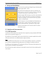
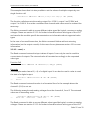
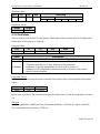
1.2 LucidControl Product Family
Fig. 1 and Fig. 2 show the available input modules of the LucidControl Product family.
LucidControl
DI4
LucidControl
AI4
LucidControl
RTD4
4 digitale Eingänge
4 analoge Eingänge
4 PT1000 Eingänge
5, 10, 24 V Pegel
1
0
0 ~ 10 V
-10 V ~ 10 V
Rt
Fig. 1 LucidControl Input Modules
LucidControl DI4 – Digital Input USB Module
This module provides 4 opto-insulated and potential-insolated digital inputs. It is available
for different input voltages in order to cover a wide range of applications.
LucidControl AI4 – Analog Input USB Module
This module provides 4 analog inputs. The module is available for various input voltage
ranges and is able to measure analog voltages e.g. as they are used in 0 ~ 10 V interfaces.
LucidControl RTD4 – RTD Input USB Module
This input module measures the temperature of 4 Pt1000 temperature sensors (RTD).
Seite 4 von 31
LucidControl Product Series, User Manual
2015-03-02
LucidControl
DO4
LucidControl
SPDT4
LucidControl
AO4
4 digitale Ausgänge
4 Relais Schalter
4 analoge Ausgänge
0 ~ 10 V
-10 V ~ 10 V
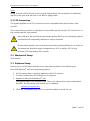
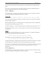
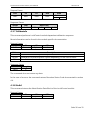
Fig. 2 LucidControl Output Modules
LucidControl DO4-I – Digital Output USB Module
This module controls 4 digital opto-insulated and potential-insulated outputs by using
solid state relays which give best overall performance for most applications.
LucidControl DO4-O – Digital Output USB Module
This module controls 4 digital open collector outputs.
LucidControl DO4-S – Digital Output USB Module
This module controls 4 SPDT relays which can be used for switching loads. It is also useful
for toggling between two analog signals like temperature sensors.
LucidControl AO4 – Analog Output USB Module
This module controls 4 analog voltage or current outputs and is available for various
ranges. It can be used to generate general purpose signals as well as to communicate with
0 ~ 10 V interfaces.
For all of these devices a module specific User Manual is available which may refer to this
document and vice versa.
Seite 5 von 31
LucidControl Product Series, User Manual
2015-03-02
2 Setup and Installation
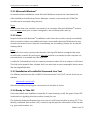
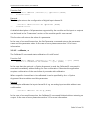
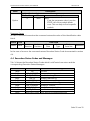
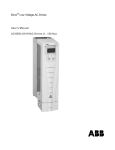
Fig. 3 shows the LucidControl Digital Output Module with 4
digital outputs (DO0 ~ DO3).
All LucidControl modules have only two connectors, the
USB-Connector and the IO-Connector. Because of this the
modules are very easy to connect and to set-up.
While the upper USB-Connector is used for interconnection
with the computer, the lower IO-Connector provides the
interface accordingly to the module function (e.g. digital
outputs or analog inputs).
The IO-Connector of most modules have 8 terminals, two
for each input or output channel. One exception is the
DO4-S module which has 3 terminals for a one output
Fig. 3 LucidControl Schematic
channel and provides an IO-Connector with 12 contacts
(illustrated in gray).
2.1 Interface and Interconnection
2.1.1 USB Connection
LucidControl USB modules are connected to the computer by using a standard USB Cable
which must not extend a length of 5 m.
All modules are “bus powered” which means that the host computer supplies the module
with power and there is no additional power supply necessary.
Note
Supplying USB devices with power is not critical using a desktop computer or notebooks
but it must be considered that the total power of one USB port is limited to 500 mA.
The USB ports of the Raspberry Pi® are limited to 100 mA. This means that maximum two
devices can be connected to a port directly.
All LucidControl are rated a maximum Current which can be found in the module specific
user manual.
Seite 6 von 31
LucidControl Product Series, User Manual
2015-03-02
Note
Using an active USB-Hub with its own power supply allows the connection of additional
devices in the case that the host is not able to supply them.
2.1.2 IO Connection
The signals applied to the IO-Connector must be compatible with the function of the
module.
The correct interconnection is described in the module specific section “IO Connection” of
the module specific user manual.
All contacts of the modules are protected against ESD but not necessarily against
overload which is especially relevant for output modules.
If the module specific user manual does not state anything different it is under no
circumstances allowed to apply voltages above 30 V or below -30 V to any
terminal. This may destroy the module.
2.2 Mechanical Setup
Text needed
2.3 Software Setup
Setting up of LucidControl modules is very easy and described in the following for
Microsoft Window® and Linux operating systems:
1 At first ensure that no signal is applied to the IO-Connector
2 Connect LucidControl via USB with your computer
3 Applies for Microsoft Windows® only:
The system asks for an installation file. This is not a driver but only an information
file (INF). The file can be download from our website:
www.lucid-control.com
4 That’s all. The green power LED is on and the module is ready for use.
Seite 7 von 31
LucidControl Product Series, User Manual
2015-03-02
2.3.1 Microsoft Windows®
As mentioned the installation under Microsoft Windows requires the information file.
After installation the Windows Device Manager contains a new serial port (COM).The
module can be accessed using this port.
Note:
Even if more than one module is connected to a computer Microsoft Windows® ensures
that the same serial port number is assigned to the module(s) after start up.
2.3.2 Linux
Despite to Microsoft Windows® installation under Linux the module is ready immediately
after connection without any additional steps. Linux installs /dev/ttyACM devices for any
module connected to the computer incrementing the succeeding number for any device
starting with 0.
Note:
By default Linux cannot ensure that the same /dev/ttyACM device is assigned the same
module after a restart. But as long as only one module is connected to the computer it is
ensured that it is accessible via /dev/ttyACM0.
LucidIoCtrl Command line tool can create a permanent static link to a unique LucidControl.
This link is also present after a restart and it can also have a more meaningful device name
like dev/digitalIoKitchen.
2.3.3 Installation of LucidIoCtrl Command Line Tool
For different architectures the LucidIoCtrl Command Line Tool (LCLT) can be found on our
website:
www.lucid-control.com
After downloading the program can be stored in a folder of choice.
2.3.4 Ready to Take-Off
Once the module was installed successfully (if it was necessary at all) the green Power LED
is switched on signaling that the module is ready for use.
The following examples illustrate how to access a LucidControl module by using LCLT. The
Identify command (see section 4.3.8) is used to request specific information of the module
e.g. type, serial number, etc.
Seite 8 von 31
LucidControl Product Series, User Manual
2015-03-02
At this moment it is only important to know that the Identify command can be used to
inspect all LucidControl modules and all modules provide similar information.
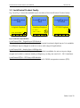
Windows Example
This example assumes that the LucidControl module is connected to comport 1.
Enter the following line in the windows prompt (console):
LucidIoCtrl –dCOM1 –i [ENTER]
Linux Example
This example assumes that the LucidControl module is connected to /dev/ttyACM0.
Enter the following line in the console:
LucidIoCtrl –d/dev/ttyACM0 –i [ENTER]
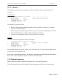
Result of both Examples
LCLT returns a console output similar to what can be seen below:
DEVICE CLASS:
DEVICE TYPE:
SERIAL NUMBER:
FIRMWARE REVISION:
HARDWARE REVISION:
1000
1000
02000000
0001
01
(DIGITAL OUTPUT 4 CHANNELS)
(SOLID STATE 24 V)
The output above represents the result of the Identify command from a digital output
module with 4 channels carried out as solid state relays (SSR).
In case of an error the chosen comport is probably wrong and the parameter should be
revised.
Seite 9 von 31
LucidControl Product Series, User Manual
2015-03-02
3 LucidIoCtrl Command Line Tool (LCLT)
3.1 Introduction
The LucidIoCtrl Command Line Tool grants easy and complete access to all functions of
LucidControl.
The easiest way to invoke LCLT is by opening a console or logging in by SSH. LCLT gives
immediately access to all LucidControl modules connected to the host computer.
LCLT was designed in order to provide a tool which runs standalone without depending on
any library and which is available for all architectures. The tool runs under Microsoft
Window® and Linux. Copying the executable file to the host computer is all needed to do.
Moreover command line tools can be integrated into nearly all applications. It does not
matter if PHP, Python, C#, Java or any other programming language is used. All of them
have the ability to run console application and to evaluate their output.
With this tool the user gets a lightweight Application Programming Interface (API) for
LucidControl that can be used even without programming knowledge by entering the
commands into the shell.
Let’s take the following example
It is assumed that the LucidControl module is connected to COM4
The output channel 0 of a digital output module should be set.
Running Microsoft Windows® prompt entering the line:
LucidCtrl –dCOM4 –c0 –w1 –tL [ENTER]
Or by entering this to the Linux shell when LucidControl is connected to
/dev/lucidIoKitchen:
./LucidCtrl –d/dev/lucidIoKitchen –c0 –w1 –tL [ENTER]
Both examples set the output to 1.
The details of the commands are described in the following sections but here it should be
explained how easy it is to work with LucidControl.
Assuming that the lines are included into a PHP script running in a webserver it is quite
obvious that LucidControl can be accessed via the internet very easily.
Seite 10 von 31
LucidControl Product Series, User Manual
2015-03-02
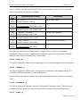
3.2 LCLT Arguments
LCLT is controlled by arguments succeeding the program name as it is usual for command
line tools. These arguments are split into two groups:
Command Arguments (Command Arguments3.2.1)
Option Arguments (3.2.2)
3.2.1 Command Arguments
Command Arguments specify which command should be executed. Only one command
argument is allowed to be used when calling LCLT.
Argument
-a
-g
-i
-r
-s
-w
Description
I/O Calibration
Read Parameter
Identify Device
Read I/O Channel(s)
Write Parameter
Write I/O Channel(s)
Tab. 1 Command Arguments
Tab. 1 shows all available Command Arguments with their short description. They are
described in this section.
3.2.1.1 --write, -w
The Write command assigns values to output cannels.
Function Call:
./LucidIoCtrl –dDEVICE –wValue(s) -cChannel(s) –tValueType [ENTER]
Examples:
This command sets output channel 0 (-c0) to 0 (-w0). Since a digital output is accessed the
value can be either 0 or 1 (-tL). This is the typical function call for setting a digital output:
./LucidIoCtrl –d/dev/LucidIo –w0 -c1 –tL [ENTER]
This command sets the analog output 2 (-c2) to a voltage (-tV) of -5.000 V (-w-5.000):
./LucidIoCtrl –d/dev/LucidIo –w-5.000 –c2 –tV [ENTER]
This command sets the analog output 3 (-c3) to a current (-tC) of 2.5 mA (-w2500):
./LucidIoCtrl –d/dev/LucidIo –w2.500 –c3 –tC [ENTER]
Seite 11 von 31
LucidControl Product Series, User Manual
2015-03-02
This example shows that it is also possible to set the values of multiple outputs by one
single function call:
./LucidIoCtrl –dLucidIo –w2.500,5.000,1.250 –c1,2,0 –tV [ENTER]
The function call above sets the analog output 0 to 1.250 V, output 1 auf 2.500V and
output 2 to 5.000 V. It must be considered that channels and values must be ordered the
same way.
The Write command is able to access different value types like logical, counters or analog
voltages. Please see section 3.2.2.3 for further information about value types of the LCLT
and see also the module specific documentation on information about supported value
types.
In the case of successful execution, the Write command finishes without returning
information (on the output console). In the case of error please see section 3.3 for more
information.
3.2.1.2 --read, -r
The Read command returns the input values of inputs. It can only be used to read the
current state of outputs. The returned value is formatted accordingly to the requested
value type.
Function Call
./LucidCtrl –dDEVICE –r -cChannel(s) –tType [ENTER]
Examples
This example reads channel 1 (-c1) of a digital input. It can also be used in order to read
the state of a digital output:
->
./LucidCtrl –d/dev/LucidIo –r -c1 –tL [ENTER]
CH1:00
The Read command returns the value in a formatted form. In the example above the
channel 1 (CH1) is not set.
The following example reads analog voltages from the channels 0, 1 and 2. The returned
values are in ascending order:
->
./LucidCtrl –d/dev/LucidIo –r –c2,0,1 –tV [ENTER]
CH0:1.250
CH1:2.500
CH2:5.000
The Read command is able to access different value types like logical, counters or analog
voltages. Please see section 3.2.2.3 for further information about value types of the LCLT
Seite 12 von 31
LucidControl Product Series, User Manual
2015-03-02
and see also the module specific documentation on information about supported value
types.
In the case of successful execution, the Read command returns the requested values. In
case of error please see section 3.3 for more information.
3.2.1.3 --setparam, -s
The Set Parameter command sets Configuration Parameters of the LucidControl module
and the IO Configuration Parameters of inputs or outputs.
Function Call
./LucidCtrl –dDEVICE {-cChannel(s)} –sParameter=Value {-p} {-y} [ENTER]
In the case that the Parameter is related to an input or output, the channel can be passed
with the Option Argument –c.
With the Option Argument –p the setting can be made persistent so that it is loaded after
the restart of the module (see section 3.2.2.6).
The Option Argument –y sets the parameter back to the default value (see section 3.2.2.7).
The Option Arguments –p and –y can be combined in order to restore the default setting
permanently.
Example
This example switches led blinking for incoming commands on. The Status LED blinks on
any received command indicating communication:
./LucidCtrl –d/dev/LucidIo –ssysSignalCmd=on [ENTER]
This example configures the digital input channel 0 for Reflect mode:
./LucidCtrl –d/dev/LucidIo –c0 –sinDiMode=reflect [ENTER]
A detailed description of all parameters supported by the module and its inputs or outputs
can be found in the “Parameters” section of the module specific user manual.
In the case of successful execution, the Set Parameter command finished without returning
an output (e.g. on the console). In the case of error please see section 3.3 for more
information.
3.2.1.4 –getparam, -g
The Get Parameter command reads Configuration Parameters of the LucidControl module
and the IO Configuration Parameters of inputs or outputs.
Seite 13 von 31
LucidControl Product Series, User Manual
2015-03-02
Function Call
->
./LucidCtrl –dDEVICE {-cChannel(s)} –gParameter [ENTER]
Parameter=Value
Example
This example returns the configuration of digital input channel 0:
->
./LucidCtrl –d/dev/LucidIo –c0 –ginDiMode [ENTER]
inDiMode=reflect
A detailed description of all parameters supported by the module and its inputs or outputs
can be found in the “Parameters” section of the module specific user manual.
This function call returns the value of a parameter.
In the case of successful execution, the Get Parameter command returns the parameter
name and the parameter value. In the case of error please see section 3.3 for more
information.
3.2.1.5 --calibrate, -a
The Calibrate IO command starts calibration of LucidControl.
Function Call
./LucidCtrl –dDEVICE {-cChannel(s)} –a {-q} {--short} {--open} [ENTER]
EXECUTE I/O CALIBRATION FOR CHANNEL … ? <y/n> [ENTER]
In the case that the optional –q Option Argument is used the Calibrate IO command is
executed immediately without asking for user confirmation. Otherwise the application
requires confirmation of the user before it proceeds with calibration.
When a specific channel has to be calibrated it can be specified by the –c Option
Argument. Most modules need this parameter.
Example
This example calibrates the input channel 0 of e.g. an analog input module without user
confirmation:
./LucidCtrl –dLucidIo –c0 –a -q [ENTER]
In the case of successful execution, the Calibrate IO command finished without retuning an
output. In the case of error please see section 3.3 for more information.
Seite 14 von 31
LucidControl Product Series, User Manual
2015-03-02
3.2.1.6 --identify, -i
The identify command returns general module information and is supported by all
modules.
Function Call
./LucidCtrl –dDEVICE -i [ENTER]
DEVICE CLASS:
xxxx
DEVICE TYPE:
1000
SERIAL NUMBER:
xxxxxxxx
FIRMWARE REVISION: xxxx
HARDWARE REVISION: xx
->
->
->
->
->
(Device Class Description)
(Device Type Description)
The identify command returns:
Device Class declaring the functionality of the module in common e.g. 4 digital
inputs or 4 analog outputs
Device Type declaring the type of device e.g. 5V inputs for a digital input module
The Serial Number is a unique 4 byte hexadecimal number
Firmware and hardware revision of the LucidControl module
Example
This example returns general module information:
->
->
->
->
->
./LucidCtrl –d/dev/LucidIo -i [ENTER]
DEVICE CLASS:
0000
(DIGITAL INPUT 4 CHANNELS)
DEVICE TYPE:
1000
(5 V)
SERIAL NUMBER:
DDCCBBAA
FIRMWARE REVISION: 0001
HARDWARE REVISION: 01
This example shows the typical output of LucidControl DI4-I-5. It provides 4 digital input
channels with 5V threshold level.
In the case of successful execution, the Identify command returns the shown information.
In the case of error please see section 3.3 for more information.
3.2.2 Option Arguments
Option Arguments specify additional settings for a Command Argument.
The following table shows all available Option Arguments with their short description:
Seite 15 von 31
LucidControl Product Series, User Manual
Argument
-b
-c
-d
-h
-p
-q
-t
-y
2015-03-02
Description
Baudrate
Channel
Device
Help
Persistent
Quiet
Value Type
Default Value
Tab. 2 Option Arguments
3.2.2.1 --channel, -c
The Option Argument Channel specifies the input or output channel for a Command
Argument. It is mandatory for the commands Read and Write.
It is also mandatory for Command Arguments Set Parameter, Get Parameter and Calibrate
IO in the case that an input or output channel has to be configured or calibrated.
3.2.2.2 --device, -d
The Option Argument Device specifies the device name of the LucidControl module. It is
mandatory for all Command Arguments.
Examples
For Microsoft Windows® operating system COM4 could be a valid device name (–dCOM4).
For Linux operating systems /dev/ttyACM0 could be a valid device name
(-d/dev/ttyACM0).
Note
For Microsoft Windows® LucidControl may use comports COM10 or higher. For these high
numbered comports the device argument must be changed since –dCOM10 does not work
for them.
The correct argument in this case is –d\\.\COMnn which can be used for any comport. If
COM10 should be accessed –d\\.\COM10 is the correct notation.
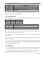
3.2.2.3 --type, -t
The Option Argument Value Type specifies the value type of Read and Write Command
Arguments and is mandatory for those.
The supported Value Types are listed in Tab. 3. Depending on the module type one or
more Value Types are supported. A digital input module for example has support for Value
Seite 16 von 31
LucidControl Product Series, User Manual
2015-03-02
Type “L” since it provides logical inputs. But it does not support Value Type “V” because
there is no analog voltage input available.
Value
Type
L
(0x00)
N
(0x0A)
A
(0x10)
V
(0x1D)
C
(0x23)
T
(0x41)
R
(0x50)
Value Range and Format
„00“ or „01“
Format Example: CH0:01
0 ~ 65535
Format Example: CH0:0x0064 (100)
0 ~ 65535
Format Example: CH0:0x0064 (100)
- 100.000 ~ 100.000 V
Format Example: CH0:-5.000
-1000.000 ~ 1000.000 mA
Format Example: CH0:-20.000
- 1000 ~ 1000 °C
Format Example: CH0:18.000
0 ~ 5000 Ω
Format Example: CH0:2500.0
Description
Digital Logic Value
Digital Counter Value
Analog Value
Voltage Value (signed)
Current Value (signed)
Temperature Value (signed)
Resistance Value
Tab. 3 Value Types
The Value type (bold printed letter) which is passed to the –t Option Argument is
translated to the byte value in parentheses. Section 4.2 gives more information how the
different Value Types are handled by LucidControl.
3.2.2.4 --help, -h
The Option Argument Help returns a help page for a Command Argument and is optional.
3.2.2.5 --default, -y
The Option Argument Default sets a Configuration Parameter to the default setting. It is
optional for the Set Parameter Command Argument.
All parameters have default settings which allow resetting a specific setting to a standard
value.
3.2.2.6 --persistent, -p
The Option Argument Persistent stores a Configuration Parameter value. The setting will
be restored after a restart. It is optional for the Set Parameter Command Argument.
3.2.2.7 --quiet, -q
Seite 17 von 31
LucidControl Product Series, User Manual
2015-03-02
The Option Argument Quiet suppresses the user confirmation message before executing a
command. It is optional for the Calibrate IO Command Argument and skips the user
confirmation.
3.2.2.8 --baudrate, -b
The Option Argument Baudrate specifies the communication speed of the used device. It is
optional and not necessary or supported by LucidControl USB modules which use a default
value of 9600 baud.
3.2.2.9 --verbose
The Option Argument Verbose Mode generates additional console output used for testing
purposes. It is optional for all Command Arguments.
3.3 Return Values
LCLT returns different return values depending on the result.
The command line tool returns an Exit Code which indicates if the tool finished with
success (Exit Code = 0) or with error (Exit Code = -1).
3.3.1 Successful Execution
In the case that the execution of the command was successful the Exit Code is set to 0 and
the tool may return data depending on the executed command.
3.3.2 Error Codes
In the case of an error the Exit Code of the command line tool is set to -1. Moreover the
tool my return some more meaningful error information.
There are two reasons why a command is not executed successfully:
1. The arguments passed to LCLT are not correct and the program returns an Error
Status Code.
2. LucidControl module returns an Error Status Code because of not successful
execution.
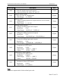
3.3.2.1 LCLT Program Status Codes (Error)
The following table contains Error Status Codes that the LucidControl Command Line Tool
returns when the arguments are parsed.
Seite 18 von 31
LucidControl Product Series, User Manual
Status Code
0x10
0x11
0x20
0x21
0x2A
0x30
0x40
0x31
0x4A
0x4B
0x90
2015-03-02
Description
Internal I/O read error
Accessing the communication interface (eg. COM1 or /dev/ttyACM0)
failed because of communication errors (e.g. Timeouts)
Invalid number of bytes received
Indicates that the number of received bytes in the LEN Field does not
correspond to the number of received bytes in the Data Field
Invalid Channel Argument
The passed channel Argument is wrong or it is missed
Invalid Multiple Channel Argument
The passed channel argument is wrong or it is missed
Invalid IO Value
The value (writing) does not correspond to the expected number of
values.
The value (writing) is not valid for the expected Value Type.
Invalid Argument Baud Rate
The port does not support the passed parameters.
Invalid or unknown Value Type
The passed Value Type is incompatible or not supported.
Invalid Device Argument specified
The device (serial port) is not available or busy (e.g. already opened).
Invalid Configuration Parameter Argument
Invalid Configuration Parameter Value Argument passed
More than one Command Argument passed
Tab. 4 LucidIoCtrl Command Line Tool Error Codes
3.3.2.2 LucidControl Module Status Codes (Error)
Tab. 4 explains the Error Codes that the LucidControl Module can return. While many
errors like wrong Option Arguments can be detected by LCLT other errors cannot. E.g.
reading a value from an obviously wrong input channel 9 by passing Option Argument –c9
cannot be detected as wrong argument since LCLT does not know which capabilities a
module have. Such errors can only be detected by the module itself.
Error Status Messages are documented in section 4.4 of this manual.
Seite 19 von 31
LucidControl Product Series, User Manual
2015-03-02
4 Communication and Commands
This chapter explains the LucidControl communication interface and the communication
protocol.
While for most users it is not necessary to understand this in detail it could be most helpful
for programmers implementing their own API (Application Programming Interface).
Since LucidControl uses the CDC profile of the USB standard it is possible to access
LucidControl modules as common serial device which has several advantages:
Standardized device driver of the operating system can be used and a driver
installation is not necessary
LucidControl can be controlled simple e.g. by using terminal programs
Portable equipment running under Microsoft Windows® as well as Linux
Newer releases of operating systems will support the device automatically
Based on the serial port LucidControl is controlled by simple data frames which are
described in this following.
4.1 Communication Frame
The data exchanged between the computer and LucidControl are packed into
communication frames.
Data sent to LucidControl are called Requests, data sent back from LucidControl are called
Responses.
The communication follows a master-slave principle where LucidControl answers to
Requests of the host only. LucidControl does not initiate a communication on its own.
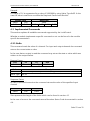
4.1.1 Request Frame
A Request Frame sent from a computer contains data for LucidControl and initiates a
communication.
OPC
1 Byte
Header Field
P1
P2
1 Byte
1 Byte
LEN
1 Byte
Data Field
Data Field
LEN Bytes
Seite 20 von 31
LucidControl Product Series, User Manual
Field
OPC
P1, P2
LEN
Data Field
2015-03-02
Description
Opcode for Request Command
Command specific Parameters
Number of Bytes in the Data Field
Data Field
Tab. 5 Request Frame
Tab. 5 shows the fields of the Request Frame. The Header Field is mandatory and the Data
Field is optional and only available if LEN > 0.
4.1.2 Response Frame
The Response Frame sent from LucidControl contains information for the host computer.
Header Field
Status
LEN
1 Byte
1 Byte
Field
Status
LEN
Data Field
Data Field
Data Field
LEN Bytes
Description
Status Code
Number of Bytes in Data Field
Data Field
Tab. 6 Response Frame
Tab. 6 explains the fields of the Response Frame. The Header Field is mandatory and the
Data Field is optional and only available for LEN > 0.
Depending on the command and the execution status LucidControl may return more or
less information.
In the case of success Status Code has a value of 0x00 and LEN indicates how many bytes
the Data Field contains.
In the case of error the Status Word is not equal to 0x00 and the Length indicates with a
value of 0x00 that the Data Field is absent. A detailed description of Error Status Codes can
be found in section 4.4 of this manual.
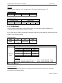
4.2 Value Types
LucidControl handles various analog and digital signals. Commands accessing the inputs
and outputs need specification of the Value Type in order to interpret the data correctly.
Tab. 7 describes the supported Value Types. The information if a LucidControl module
supports a Value Type can be found in the module specific user manual.
Seite 21 von 31
LucidControl Product Series, User Manual
Value Type
0x00
0x0A
0x10
0x1C
0x1D
0x23
0x40
0x41
0x50
2015-03-02
Description
Size
Digital Logic Value
Value for digital inputs and outputs.
Supported values are either “00” and “01”.
Digital Counter Value
Input Counter for Digital Inputs.
Value Range:
0 ~ 65,535
Analog Value
Value for analog inputs and outputs without unit or further
specification.
Value Range: 0 ~ 65,535
Voltage Value (signed)
Voltage of analog inputs and outputs
Resolution:
1 mV
Value Range: -30,000 mV ~ 30,000 mV
Voltage Value (signed)
Voltage for analog inputs and outputs
Resolution:
1 µV
Value Range: -100,000,000 µV ~ 100,000,000 µV
Current Value (signed)
Current for analog inputs and outputs
Resolution:
1 µA
Value Range: -1,000,000 µA ~ 1,000,000 µA
Temperature Value (signed)
Temperature of RTD inputs
Resolution:
1/10 K
Value Range: -1,000 °C ~ 1,000 °C
Values:
-10,000 ~ 10,000
Temperature Value (signed)
Temperature for RTD inputs
Resolution:
1/100 K
Value Range: -1,000 °C ~ 1,000 °C
Values:
-100,000 ~ 100,000
Resistance Value
Resistance Value of RTD inputs
Resolution:
1/10 Ω
Value Range: 0 ~ 5,000 Ω
1 Byte
2 Bytes
2 Bytes
2 Bytes
4 Bytes
4 Bytes
2 Bytes
4 Bytes
2 Bytes
Tab. 7 Value Types
Note
Values are represented in little-endian byte order.
Seite 22 von 31
LucidControl Product Series, User Manual
2015-03-02
Example
A voltage of 5 V is represented by a value of 5,000,000 by using Value Type 0x1D. In the
case the value is read from a module the Response Frame looks like this:
Header Field
Status
LEN
0x00
0x04
0x40
Data Field
Value
0x4B 0x4C
0x00
4.3 Implemented Commands
This section explains all available commands supported by the LucidControl.
Whether a module implements a specific command or not can be found in the module
specific documentation.
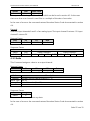
4.3.1 GetIo
This command reads the value of a channel. For input and output channels the command
returns the current state or value.
In the case that an output is read the command may return the state or value which was
written to the output before.
Request Frame
OPC
P1
0x46
Channel
P2
Value Type
LEN
0
Value
Description
Channel
Number of input or output channel (Range: 0 ~ 3)
Value Type See 4.2
Tab. 8 GetIo Request
Response Frame
In case of successful execution the command returns the value of the specified input
channel.
Status
Status
LEN
Size
Data Field
Value
Size represents the length of the Value which can be found in section 4.2.
In the case of an error the command returns Execution Status Code documented in section
4.4.
Seite 23 von 31
LucidControl Product Series, User Manual
2015-03-02
Example
Read the Input channel 3 of a voltage input. The input channel returns -5V.
Request Frame
OPC
P1
0x46
0x03
Response Frame
Header Field
Status
LEN
0x00
0x04
P2
0x1D
0xC0
LEN
0
Data Field
Value
0xB4 0xB3
0xFF
4.3.2 GetIoGroup
This command reads a group of channel values. For input and output channels the
command returns the current states or values.
In the case that an output is read the command may return the states or values which were
written to the output before.
Request Frame
OPC
0x48
P1
Channel
Mask
P2
LEN
Value Type
0
Value
Description
Channel Bit Mask specifying the channel number(s)
Channel
Bit Position
Value
0
0
0x01
1
1
0x02
Channel
2
2
0x04
Mask
3
3
0x08
Values can be bitwise combined.
Examples
Accessing channel numbers 0 and 3
Value = 0x01 OR 0x08 = 0x09
Accessing channel numbers 1 and 2
Value = 0x02 OR 0x04 = 0x06
Value Type See 4.2
Tab. 9 GetIoGroup Request
Response Frame
In case of successful execution the command returns the value of the input channels
specified in the Channel Mask.
Seite 24 von 31
LucidControl Product Series, User Manual
2015-03-02
Status
LEN
Data Field
Status
Size
Value(s)
Size represents the length of the value(s) which can be found in section 4.2. In the case
that more than one channel is read Size is a multiple of the size of one value.
In the case of an error the command returns Execution Status Code documented in section
4.4.
Example
Read the input channels 0 and 3 of an analog input. The input channel 0 returns -5V input
channel 3 returns 5V.
Request Frame
OPC
P1
0x48
0x09
Response Frame
Header Field
Status
LEN
0x00
0x08
P2
0x1D
LEN
0
Data Field
Value Channel 0
0xC0 0xB4 0xB3 0xFF
Value Channel 3
0x00 0x40 0x4B 0x4C
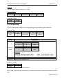
4.3.3 SetIo
This Command assigns a value to an output channel.
Request Frame
OPC
P1
0x40
Channel
Value
Channel
Value Type
Length
Value
P2
Value Type
LEN
Length
Data
Value
Description
Number output channel (Range: 0 ~ 3)
See 4.2
Size of the value (See 4.2)
Value to write
Tab. 10 SetIo Request
Response Frame
Status
Length
Status
0
The command does not return any data.
In the case of an error the command returns Execution Status Code documented in section
4.4.
Seite 25 von 31
LucidControl Product Series, User Manual
2015-03-02
Example
Set the digital output channel 1 to “High”
Request Frame
OPC
P1
0x40
0x01
P2
0x00
LEN
0x01
Data
0x01
Response Frame
Status
Length
0x00
0x00
4.3.4 SetIoGroup
This command writes values of the same value type to multiple output channels.
Request Frame
OPC
0x42
P1
Channel
Mask
P2
LEN
Data
Value Type
Length
Value(s)
Value
Description
Channel Bit Mask specifying the channel number(s)
Channel
Bit Position
Value
0
0
0x01
1
1
0x02
Channel
2
2
0x04
Mask
3
3
0x08
Values can be bitwise combined.
Examples
Accessing channel number 0 and 3
Value = 0x01 OR 0x08 = 0x09
Accessing channel number 1 and 2
Value = 0x02 OR 0x04 = 0x06
Value Type See 4.2
Value(s)
One or more values to set
Tab. 11 SetIoGroup Request
Response Frame
Status
Length
Status
0
The command does not return any data.
In the case of an error the command returns Execution Status Code documented in section
4.4.
Seite 26 von 31
LucidControl Product Series, User Manual
2015-03-02
Example
Set output channels 0 and 3 of a voltage output to 2.5 V and 5.0 V.
Request Frame
OPC
P1
P2
LEN
0x42
0x08
0x09
0x1D
Data Field
Value Channel 0
0x00 0xA0 0x25 0x26
Value Channel 3
0x00 0x40 0x4B 0x4C
Response Frame
Status
Length
0x00
0x00
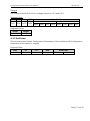
4.3.5 SetParam
This command sets System Configuration Parameters of the module and IO Configuration
Parameters of the inputs or outputs.
Request Frame
OPC
P1
0xA0
Channel
P2
Option
LEN
Length
Data Field
P-Address
P-Value
Seite 27 von 31
LucidControl Product Series, User Manual
Value
Channel
Option
Length
P-Address
P-Value
2015-03-02
Description
Channel number for input or output channel configuration parameters
Parameter Set Options
Bit Position
Value
Description
Set Default
If bit is set the parameter value is set
0
0x01
to its default value. Length must be
set to 0 and Data Field must be
omitted.
Persistent Parameter
7
0x80
Parameter is saved and restored on
module startup.
Values can be bitwise or combined
Length of the Data Field containing parameter address and parameter value.
Must be at least 0x02 which is the length of the parameter address.
Parameter Address
This value specifies the 2 Byte address of the parameter
Addresses of system parameters can be found in section 0.
Adresses of IO configuration parameters can be found in the module
specific documentation.
Parameter Value
Tab. 12 SetParam Request
Response Frame
Status
Length
Status
0
The command does not return any data.
In the case of an error the command returns Execution Status Code documented in section
4.4.
Example
Set the IO configuration parameter outDiCycleTime (Parameter Address = 0x1110) of
output channel 0 to 750 ms and make it persistent. The parameter has a length of 4 Bytes.
Seite 28 von 31
LucidControl Product Series, User Manual
Request Frame
OPC
P1
P2
0xA0
0
0x80
LEN
0x06
2015-03-02
P-Address
0x10 0x11
Data Field
P-Value
0xB0 0x71 0x0B
0x00
Response Frame
Status
Length
0x00
0x00
4.3.6 GetParam
This command read System Configuration Parameters of the module and IO Configuration
Parameters of the inputs or outputs.
Request Frame
OPC
P1
0xA2
Channel
Value
Channel
P-Address
P2
0x00
LEN
0x02
Data
P-Address
Description
Channel number for input or output channel configuration parameters
Parameter Address
This value specifies the 2 Byte address of the parameter
Addresses of system parameters can be found in section 0.
Adresses of IO configuration parameters can be found in the module
specific documentation.
Response Frame
In case of successful execution the command returns the value of the specified parameter
value.
Status
Status
LEN
Size
Data Field
P-Value
In the case of an error the command returns Execution Status Code documented in section
4.4.
Example
Read the parameter outDiCycleTime (Parameter Address = 0x1110) of output channel 0.
The command returns a value of 750 ms.
Seite 29 von 31
LucidControl Product Series, User Manual
Request Frame
OPC
0xA2
2015-03-02
P1
P2
LEN
0x00
0x00
0x02
Response Frame
Status
LEN
0x00
0x04
0xB0
Data Field
0x71 0x0B
Data
P-Address
0x10 0x11
0x00
4.3.7 CalibrateIo
This command performs LucidControl module dependent calibration sequence.
More information can be found in the module specific documentation.
Request Frame:
OPC
P1
0x52
Channel
Value
Channel
Option
LEN
P2
Option
LEN
0
Description
Channel number for input or output calibration
Calibration command specific option depending on the used module.
Data Field is absent
Response Frame
Status
Length
Status
0
The command does not return any data.
In the case of an error the command returns Execution Status Code documented in section
4.4.
4.3.8 GetId
This command returns the Identification Data Block of the LucidControl module.
Request Frame
OPC
P1
0xC0
0x00
P2
Option
LEN
0
Seite 30 von 31
LucidControl Product Series, User Manual
2015-03-02
Value
Description
Get Identification Option
Bit Position
Value
0
0x01
Option
Description
Blink
If set the parameter value is set the
STATE Led of the module blinks
once. This can help to find a specific
module.
Tab. 13 GetId Request
Response Frame
In case of successful execution the command returns the value of the identification data
block.
Status
LEN
Status
0x10
Firmware
Revision
Hardware
Revision
Data Field
Device
Device
Class
Type
Device
Serial No.
Reserved
In the case of an error the command returns Execution Status Code documented in section
4.4.
4.4 Execution Status Codes and Messages
Tab. 14 shows the Execution Status Codes which LucidControl can return and the
corresponding Execution Status Messages.
Status Code
0x00
0xA0
0xB0
0xB2
0xB4
0xB6
0xB8
0xBA
0xC0
0xD0
Status
OK
NO_SUPPORT
INV_LENGTH
INV_P1
INV_P2
INV_VALUE
INV_CHANNEL
INV_PARAM
INV_DATA
ERR_EXECUTION
Status Message
Success
Command not supported
Invalid data length
Invalid Parameter P1
Invalid Parameter P2
Invalid Value or Value Type
Invalid IO Channel
Invalid Parameter Address
Invalid data in Data Field
Error during command execution
Tab. 14 Execution Status Codes
Seite 31 von 31