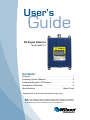
1
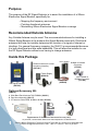
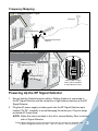
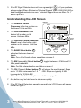
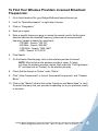
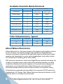
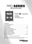
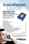
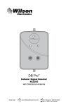
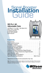
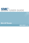
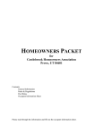
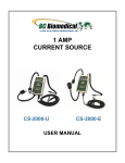
User’s
RF Signal Detector
Model #2E7501
Contents:
Purpose. . . . . . . . . . . . . . . . . . . . . . . . . . . . . . . . . . . . . . 1
Powering Up the Detector. . . . . . . . . . . . . . . . . . . . . . . . 2
Understanding the LCD Screen. . . . . . . . . . . . . . . . . . . .3
Guarantee & Warranty. . . . . . . . . . . . . . . . . . . . . . . . . . . 6
Specifications . . . . . . . . . . . . . . . . . . . . . . . . . Back Cover
Appearance of device and accessories may vary.
Note: This manual contains important safety and operating information.
Please read and follow the instructions in this manual. Failure to do so could
be hazardous and result in damage to your Signal Detector.
Purpose
The purpose of the RF Signal Detector is to assist the installation of a Wilson
Electronics Signal Booster, specifically for:
• Mapping the frequency environment
• Pointing directional antennas
• Maximizing Wilson Electronics Signal Booster coverage
Recommended Outside Antenna
Any Outside Antenna may be used. The recommended antenna for installing a
Wilson Signal Booster is the antenna the Signal Booster came with. Directional
antennas will help the installer determine the location of a signal-of-interest or
interferer. For general frequency mapping, the 304411 is recommended because
it is both directional and has wide bandwidth. This will allow the installer to use
the RF Signal Detector without ever having to change antennas.
Inside this Package
Rubber Antenna for indoor
frequency mapping
(301144 )
Velcro Stickers
Power Supply
(859912)
Battery Pack
(859996)
RF Signal Detector
(867501)
N-Male to N-Male
Connector
(971149)
TNC-Female to
N-Male Connector
(971148)
Optional Accessory Kit:
(308410)
A. Wide-Band Panel Antenna 700-2700MHz (304411)
B. Pole Mount Assembly (901117)
C. 2’ Extension Cable RG58, N-Male to N-Male (951134)
A.
B.
C.
Appearance of device and accessories may vary.
1
To purchase, contact Wilson Electronics Sales Department at: 800-204-4104
Contact Wilson Electronics Technical Support Team with any questions at 866-294-1660
or email: [email protected]. Mon.-Fri. Hours: 7 am to 6 pm MST.
Frequency Mapping
Finding Strongest Outdoor Signal
Cell Tower
RF Signal Detector
Wide Band Directional
Antenna
Checking Inside Coverage Area
Inside Panel Antenna
Power
872.75
1.5 -98
RF SIGNAL DETECTOR
BAND
Select
BW
Select
CH
Select
RF Signal Detector
Check inside coverage
before & after installation
of Signal Booster system.
Powering Up the RF Signal Detector
1. Ensure that the Outside Antenna cable or Rubber Antenna is connected to
the RF Signal Detector and the connection is tight before powering up the RF
Signal Detector.
2. Plug the AC power supply or battery pack into the RF Signal Detector input
marked “6V DC” (carefully, to avoid damaging the center pin). Plug into surge
protected AC Power Strip.
NOTE: Utilize the velcro included in this kit to secure Battery Pack to bottom side of Signal Detector.
Contact Wilson Electronics Technical Support Team with any questions at 866-294-1660
or email: [email protected]. Mon.-Fri. Hours: 7 am to 6 pm MST.
2
Power
3. If the RF Signal Detector does not have a green light
or if you questions,
please contact Wilson Electronics Technical Support Team at 866-294-1660 or
email [email protected]. Technical Support hours
are Mon.- Fri. 7
872.75
am to 6 pm MST.
1.5 -98
Understanding the LCD Screen
BAND
Select
Figure 1
1. The Downlink Center
Frequency is the top number on
the screen. Units are MHz.
BW
Select
CH
Select
Power
2. The Pass Bandwidth is the
bottom left number on the
screen. Units are MHz.
Power
Pass Bandwidth
3. The Detected Cellular Downlink
872.75
Signal Level is the bottom right
1.5 -98
number on the screen. Units are
dBm.
872.75
1.5 -98
Downlink Center
Frequency
Detected Cellular
Downlink Signal
Power
BAND
BW
Select
Select
4. The BAND Select button
872.75
will select between downlink
1.5 -98
bands.
Note: For a list of band options see tables on page 4.
BAND
Select
BW
Select
CH
Select
CH
Select
Power
872.75
5. The BW (bandwidth) Select button
toggles between 1.5 MHz and 10
1.5 -98
MHz pass bandwidth.
Note: For filter characteristics see tables on page 4.
BAND
Select
BAND
Select
BW
Select
BW
Select
CH
Select
CH
Select
6. The CH (Channel) Select button
will step to the next channel. Steps
are in 1.5 MHz increments for 1.5 MHz BW. Steps are typically 5 MHz
increments for 10 MHz BW.
Note: For a list of channel options see tables on page 4.
7. Any button may be held down to step more quickly.
8. If the RF Signal Detector is operating normally the LCD Screen will appear
similar to Figure 1.
3
Contact Wilson Electronics Technical Support Team with any questions at 866-294-1660
or email: [email protected]. Mon.-Fri. Hours: 7 am to 6 pm MST.
To Find Your Wireless Providers Licensed Broadcast
Frequencies:
1. Go to http://wireless2.fcc.gov/UlsApp/UlsSearch/searchLicense.jsp
2. Look for “Specialized search” on right side of screen.
3. Click on “Geographic.”
4. Enter your region.
5. Enter a specific frequency range to narrow the search results. As the signal
detector indicates the downlink frequency, below are the recommended
frequency ranges to search for each band:
- 700 MHz - Search “728-757”
- 850 MHz - Search “869-894”
- 1900 MHz - Search “1930-1990”
- AWS - Search “2110-2155”
6. Click Search.
7. On the Search Results page, click on the wireless provider of interest
NOTE: Most will show the wireless provider’s name. If it does not show the wireless provider’s name, then select the “Call Sign/Lease ID” and then look at “Contact” for the wireless provider.
8. Check that the license is “Active” under “Status.”
9. Click “(View Frequencies)” or look at “Associated Frequencies” and “Channel
Block.”
10. Click on the “Market” tab and look at the “Spectrum and Market Area” to verify
the exact frequency that your provider is operating on in your particular county
or counties.
Contact Wilson Electronics Technical Support Team with any questions at 866-294-1660
or email: [email protected]. Mon.-Fri. Hours: 7 am to 6 pm MST.
4
Available Downlink Bands/Channels
Downlink Center Frequency
Highest Center
Frequency (MHz)
Downlink Band
Pass Bandwidth (MHz)
Lowest Center
Frequency (MHz)
850 MHz (Cellular)
1.5
869.75
895.25
10
874.5
896.5
1.5
1930.75
1989.25
10
1935
1985
1.5
2110.75
2154.25
10
2115
2150
1.5
728.75
755.75
10
733
751
1900 MHz (PCS)
1700/2100 MHz (AWS)
700 MHz (Band 12 & 13)
Filter Characteristics, Typical
Pass Bandwidth (MHz)
-3dB BW (MHz)
-40dB BW (MHz)
-45dB BW (MHz)
1.5
1.5
4.45
4.65
10
9.9
12.9
13.2
About Wilson Electronics
Wilson Electronics, Inc. has been a leader in the wireless communications industry
for over 40 years. The company designs and manufactures Signal Boosters,
Antennas and related components that significantly improve cellular phone signal
reception and transmission in a wide variety of applications, both mobile (marine,
RV, vehicles) and in-building (home, office, M2M).
With extensive experience in antenna and Signal Booster research and design, the
company’s engineering team uses a state-of-the-art testing laboratory, including
an anechoic chamber and network analyzers, to fine-tune antenna designs and
performance. For its Signal Boosters, Wilson Electronics uses a double RF
electrically shielded enclosure and cell tower simulators for compliance testing.
All products are engineered and assembled in the company’s 55,000-square-foot
headquarters in St. George, Utah. Wilson Electronics has product dealers in all 50
states as well as in countries around the world.
5
Contact Wilson Electronics Technical Support Team with any questions at 866-294-1660
or email: [email protected]. Mon.-Fri. Hours: 7 am to 6 pm MST.
30-Day Money-Back Guarantee
All Wilson Electronics products are protected by Wilson Electronics 30-day money-back
guarantee. If for any reason the performance of any product is not acceptable, simply return
the product directly to the reseller with a dated proof of purchase.
1-Year Warranty
Wilson Electronics Signal Boosters are warranted for one (1) year against defects in
workmanship and/or materials. Warranty cases may be resolved by returning the product
directly to the reseller with a dated proof of purchase.
Signal Boosters may also be returned directly to the manufacturer at the consumer’s
expense, with a dated proof of purchase and a Returned Material Authorization (RMA)
number supplied by Wilson Electronics. Wilson Electronics shall, at its option, either repair
or replace the product. Wilson Electronics will pay for delivery of the repaired or replaced
product back to the original consumer if located within the continental U.S.
This warranty does not apply to any Signal Booster determined by Wilson Electronics to
have been subjected to misuse, abuse, neglect, or mishandling that alters or damages
physical or electronic properties.
Failure to use a surge protected AC Power Strip with at least a 1000 Joule rating will void
your warranty.
RMA numbers may be obtained by contacting Technical Support at 866-294-1660.
Disclaimer : The information provided by Wilson Electronics, Inc. is believed to be
complete and accurate. However, no responsibility is assumed by Wilson Electronics,
Inc. for any business or personal losses arising from its use, or for any infringements of
patents or other rights of third parties that may result from its use.
Copyright © 2012 Wilson Electronics, Inc. All rights reserved.
U.S. Patent Nos. – 7,729,669; 7,486,929
Contact Wilson Electronics Technical Support Team with any questions at 866-294-1660
or email: [email protected]. Mon.-Fri. Hours: 7 am to 6 pm MST.
6
RF Signal Detector Specifications
RF Signal Detector Specifications
Model Number
2E7501
Antenna connector
N-Type
Antenna impedance
50 ohms
Dimensions
Weight
5.7 x 4.2 x 1.5 inch (14.0 x 10.8 x 3.9 cm)
1.24 lbs
Maximum detectable in-band signal (dBm)
-38
Minimum detectable in-band signal with 1.5MHz BW (dBm)
-110
Minimum detectable in-band signal with 10MHz BW (dBm)
-105
Maximum recommended RF input (dBm)
Power Requirements
-38
110-240 V AC, 50-60 Hz, 4.2W or 6V DC, 700mA
3301 East Deseret Drive, St. George, UT 84790
For additional Technical Support visit www.WilsonElectronics.com
or email: [email protected]
Phone: 866-294-1660 Local: 435-673-5021 Fax: 435-656-2432
www.twitter.com/WilsonCellular
www.facebook.com/WilsonCellular
111081_RF Signal Detector_Rev05_07.25.12